CN101002670B - Subject information analysis device, endoscope device, subject information analysis method - Google Patents
Subject information analysis device, endoscope device, subject information analysis method Download PDFInfo
- Publication number
- CN101002670B CN101002670B CN2007100024434A CN200710002443A CN101002670B CN 101002670 B CN101002670 B CN 101002670B CN 2007100024434 A CN2007100024434 A CN 2007100024434A CN 200710002443 A CN200710002443 A CN 200710002443A CN 101002670 B CN101002670 B CN 101002670B
- Authority
- CN
- China
- Prior art keywords
- light
- information
- unit
- subject
- ultrasonic
- Prior art date
- Legal status (The legal status is an assumption and is not a legal conclusion. Google has not performed a legal analysis and makes no representation as to the accuracy of the status listed.)
- Expired - Fee Related
Links
Images


Classifications
-
- G—PHYSICS
- G09—EDUCATION; CRYPTOGRAPHY; DISPLAY; ADVERTISING; SEALS
- G09F—DISPLAYING; ADVERTISING; SIGNS; LABELS OR NAME-PLATES; SEALS
- G09F15/00—Boards, hoardings, pillars, or like structures for notices, placards, posters, or the like
- G09F15/0087—Boards, hoardings, pillars, or like structures for notices, placards, posters, or the like including movable parts, e.g. movable by the wind
-
- A—HUMAN NECESSITIES
- A61—MEDICAL OR VETERINARY SCIENCE; HYGIENE
- A61B—DIAGNOSIS; SURGERY; IDENTIFICATION
- A61B5/00—Measuring for diagnostic purposes; Identification of persons
- A61B5/0059—Measuring for diagnostic purposes; Identification of persons using light, e.g. diagnosis by transillumination, diascopy, fluorescence
-
- A—HUMAN NECESSITIES
- A61—MEDICAL OR VETERINARY SCIENCE; HYGIENE
- A61B—DIAGNOSIS; SURGERY; IDENTIFICATION
- A61B5/00—Measuring for diagnostic purposes; Identification of persons
- A61B5/0048—Detecting, measuring or recording by applying mechanical forces or stimuli
-
- A—HUMAN NECESSITIES
- A61—MEDICAL OR VETERINARY SCIENCE; HYGIENE
- A61B—DIAGNOSIS; SURGERY; IDENTIFICATION
- A61B5/00—Measuring for diagnostic purposes; Identification of persons
- A61B5/0093—Detecting, measuring or recording by applying one single type of energy and measuring its conversion into another type of energy
- A61B5/0095—Detecting, measuring or recording by applying one single type of energy and measuring its conversion into another type of energy by applying light and detecting acoustic waves, i.e. photoacoustic measurements
-
- G—PHYSICS
- G09—EDUCATION; CRYPTOGRAPHY; DISPLAY; ADVERTISING; SEALS
- G09F—DISPLAYING; ADVERTISING; SIGNS; LABELS OR NAME-PLATES; SEALS
- G09F15/00—Boards, hoardings, pillars, or like structures for notices, placards, posters, or the like
- G09F15/0006—Boards, hoardings, pillars, or like structures for notices, placards, posters, or the like planar structures comprising one or more panels
- G09F15/0012—Boards, hoardings, pillars, or like structures for notices, placards, posters, or the like planar structures comprising one or more panels frames therefor
-
- G—PHYSICS
- G09—EDUCATION; CRYPTOGRAPHY; DISPLAY; ADVERTISING; SEALS
- G09F—DISPLAYING; ADVERTISING; SIGNS; LABELS OR NAME-PLATES; SEALS
- G09F15/00—Boards, hoardings, pillars, or like structures for notices, placards, posters, or the like
- G09F15/0006—Boards, hoardings, pillars, or like structures for notices, placards, posters, or the like planar structures comprising one or more panels
- G09F15/0037—Boards, hoardings, pillars, or like structures for notices, placards, posters, or the like planar structures comprising one or more panels supported by a post
-
- G—PHYSICS
- G09—EDUCATION; CRYPTOGRAPHY; DISPLAY; ADVERTISING; SEALS
- G09F—DISPLAYING; ADVERTISING; SIGNS; LABELS OR NAME-PLATES; SEALS
- G09F15/00—Boards, hoardings, pillars, or like structures for notices, placards, posters, or the like
- G09F15/0068—Modular articulated structures, e.g. stands, and articulation means therefor
-
- G—PHYSICS
- G09—EDUCATION; CRYPTOGRAPHY; DISPLAY; ADVERTISING; SEALS
- G09F—DISPLAYING; ADVERTISING; SIGNS; LABELS OR NAME-PLATES; SEALS
- G09F19/00—Advertising or display means not otherwise provided for
- G09F19/02—Advertising or display means not otherwise provided for incorporating moving display members
-
- A—HUMAN NECESSITIES
- A61—MEDICAL OR VETERINARY SCIENCE; HYGIENE
- A61B—DIAGNOSIS; SURGERY; IDENTIFICATION
- A61B5/00—Measuring for diagnostic purposes; Identification of persons
- A61B5/0059—Measuring for diagnostic purposes; Identification of persons using light, e.g. diagnosis by transillumination, diascopy, fluorescence
- A61B5/0062—Arrangements for scanning
- A61B5/0066—Optical coherence imaging
-
- A—HUMAN NECESSITIES
- A61—MEDICAL OR VETERINARY SCIENCE; HYGIENE
- A61B—DIAGNOSIS; SURGERY; IDENTIFICATION
- A61B5/00—Measuring for diagnostic purposes; Identification of persons
- A61B5/0059—Measuring for diagnostic purposes; Identification of persons using light, e.g. diagnosis by transillumination, diascopy, fluorescence
- A61B5/0075—Measuring for diagnostic purposes; Identification of persons using light, e.g. diagnosis by transillumination, diascopy, fluorescence by spectroscopy, i.e. measuring spectra, e.g. Raman spectroscopy, infrared absorption spectroscopy
-
- A—HUMAN NECESSITIES
- A61—MEDICAL OR VETERINARY SCIENCE; HYGIENE
- A61B—DIAGNOSIS; SURGERY; IDENTIFICATION
- A61B5/00—Measuring for diagnostic purposes; Identification of persons
- A61B5/0059—Measuring for diagnostic purposes; Identification of persons using light, e.g. diagnosis by transillumination, diascopy, fluorescence
- A61B5/0082—Measuring for diagnostic purposes; Identification of persons using light, e.g. diagnosis by transillumination, diascopy, fluorescence adapted for particular medical purposes
- A61B5/0084—Measuring for diagnostic purposes; Identification of persons using light, e.g. diagnosis by transillumination, diascopy, fluorescence adapted for particular medical purposes for introduction into the body, e.g. by catheters
-
- A—HUMAN NECESSITIES
- A61—MEDICAL OR VETERINARY SCIENCE; HYGIENE
- A61B—DIAGNOSIS; SURGERY; IDENTIFICATION
- A61B5/00—Measuring for diagnostic purposes; Identification of persons
- A61B5/72—Signal processing specially adapted for physiological signals or for diagnostic purposes
- A61B5/7235—Details of waveform analysis
- A61B5/7253—Details of waveform analysis characterised by using transforms
- A61B5/7257—Details of waveform analysis characterised by using transforms using Fourier transforms
-
- A—HUMAN NECESSITIES
- A61—MEDICAL OR VETERINARY SCIENCE; HYGIENE
- A61B—DIAGNOSIS; SURGERY; IDENTIFICATION
- A61B5/00—Measuring for diagnostic purposes; Identification of persons
- A61B5/72—Signal processing specially adapted for physiological signals or for diagnostic purposes
- A61B5/7235—Details of waveform analysis
- A61B5/7253—Details of waveform analysis characterised by using transforms
- A61B5/726—Details of waveform analysis characterised by using transforms using Wavelet transforms
-
- A—HUMAN NECESSITIES
- A61—MEDICAL OR VETERINARY SCIENCE; HYGIENE
- A61B—DIAGNOSIS; SURGERY; IDENTIFICATION
- A61B8/00—Diagnosis using ultrasonic, sonic or infrasonic waves
- A61B8/12—Diagnosis using ultrasonic, sonic or infrasonic waves in body cavities or body tracts, e.g. by using catheters
Landscapes
- Health & Medical Sciences (AREA)
- Life Sciences & Earth Sciences (AREA)
- Physics & Mathematics (AREA)
- Engineering & Computer Science (AREA)
- Animal Behavior & Ethology (AREA)
- General Health & Medical Sciences (AREA)
- Biophysics (AREA)
- Biomedical Technology (AREA)
- Heart & Thoracic Surgery (AREA)
- Medical Informatics (AREA)
- Molecular Biology (AREA)
- Surgery (AREA)
- Veterinary Medicine (AREA)
- Pathology (AREA)
- Public Health (AREA)
- General Physics & Mathematics (AREA)
- Theoretical Computer Science (AREA)
- Acoustics & Sound (AREA)
- Business, Economics & Management (AREA)
- Accounting & Taxation (AREA)
- Marketing (AREA)
- Ultra Sonic Daignosis Equipment (AREA)
- Investigating Or Analysing Materials By Optical Means (AREA)
- Endoscopes (AREA)
Abstract
Description
技术领域 technical field
本发明涉及一种利用超声波来光学分析被检体的被检体信息分析装置、内窥镜装置、以及被检体信息分析方法。 The present invention relates to a subject information analysis device, an endoscope device, and a subject information analysis method for optically analyzing a subject using ultrasonic waves. the
背景技术Background technique
近年来,作为生物体的光学断层成像,提出或者实用化了光学CT、光学相干断层成像法(Optical Coherence Tomography:光学相干断层成像,以下称为OCT)、光声断层成像法等各种技术。 In recent years, various techniques such as optical CT, optical coherence tomography (Optical Coherence Tomography, hereinafter referred to as OCT), and photoacoustic tomography have been proposed or put into practical use as optical tomography of living bodies. the
光学CT由于利用生物体内部中光散射影响较弱的波长域700nm~1200nm的近红外光,因此能够得到粘膜下数cm为止的生物体深部的断层图像。 Optical CT utilizes near-infrared light in the wavelength range of 700nm to 1200nm in which light scattering is weakly affected inside the living body, and thus can obtain tomographic images of the deep part of the living body up to a few centimeters below the mucous membrane. the
另外,利用了干涉的OCT,能够以高分辨率(μm~十数μm)且短时间取得到2mm左右深度为止的生物体断层图像。OCT是在眼科领域中的网膜疾病诊断中已经实用化的技术,其医学关注程度非常高。 In addition, OCT using interference can acquire a tomographic image of a living body up to a depth of about 2 mm at high resolution (μm to tens of μm) in a short time. OCT is a technique that has already been put to practical use in the diagnosis of omental diseases in the field of ophthalmology, and its medical attention is very high. the
光学CT能够得到深部的信息,但是空间分辨率是数mm左右,非常低。另一方面,OCT难以观测生物体粘膜下比约2mm更深的深度、并且对于癌等肿瘤组织难以得到良好的像质。 Optical CT can obtain deep information, but the spatial resolution is only a few millimeters, which is very low. On the other hand, it is difficult for OCT to observe the submucosal depth of a living body deeper than about 2 mm, and it is difficult to obtain good image quality for tumor tissues such as cancer. the
这是由于在生物体深部以及肿瘤组织中,由于血液的吸收、强散射的影响,光的相干性显著紊乱。 This is because the coherence of light is significantly disturbed due to the absorption of blood and the influence of strong scattering in the deep part of the living body and tumor tissue. the
另一方面,在日坂等的非专利文献1“日坂真樹、杉浦忠男、河田聡、″パルス超音波と光の相互作用を利用した散乱体深部の光断 像観察″,光学29、pp631-634、2000”中,报告了如下的例子:用超声波和光照射生物体,通过检测在生物体内由脉冲超声波进行了调制的照射光,尝试进行粘膜表层 以下1cm左右的吸收的光学成像。
On the other hand, in the
另外,在专利文献1的日本特开2005-224399号公报中,也公开了如下装置:将超声波脉冲和光照射到生物体,通过检测在生物体内由脉冲超声波进行了调制的照射光,得到粘膜表层以下的吸收光学成像。
In addition, Japanese Patent Application Laid-Open No. 2005-224399 of
但是,上述专利文献1、非专利文献1的现有例,只不过是特定为光的吸收成像的例子,不是能得到由于组织结构、构造的变化而引起的光的散射信息的技术。
However, the above-mentioned conventional examples of
也就是说,伴随着生物体组织中的肿瘤癌化的核内染色体的浓缩状态、核的空间分布变化等的组织构造变化,尤其引起光散射特性的变化。因此期待能够得到与有关癌组织等的组织构造变化相关性高的散射的光学成像信息。 In other words, changes in tissue structure, such as the concentration state of chromosomes in the nucleus and changes in the spatial distribution of nuclei accompanying tumor canceration in living tissue, cause changes in light scattering characteristics, among others. Therefore, it is expected to be able to obtain scattered optical imaging information that is highly correlated with tissue structural changes such as cancerous tissues. the
此外,与组织的构造变化相关性高的散射,来源于该组织部位的复折射率的实部,另一方面,复折射率的虚部与吸收关联。因此通过捕捉复折射率实部和虚部的变化,能够得到与散射特性以及吸收特性有关的二维或者三维信息。 In addition, scattering that is highly correlated with structural changes in tissue originates from the real part of the complex refractive index of the tissue site, while the imaginary part of the complex refractive index is related to absorption. Therefore, by capturing the changes in the real and imaginary parts of the complex refractive index, two-dimensional or three-dimensional information related to the scattering characteristics and absorption characteristics can be obtained. the
另一方面,专利文献2的日本特开2000-197635号公报中,根据扩散型波动方程式公开了如下方法:使超声波会聚照射在生物体上,且从激光等多个光源从各个方向照射光,由配置在生物体周围的多个检测器检测在超声波被会聚的区域中被散射的光,从而记录散射系数和吸收系数。
On the other hand, in Japanese Patent Laid-Open No. 2000-197635 of
该专利文献2的现有例要使用多个光源以及检测器,因此存在将它们设置为能够测定的状态的操作需要消耗较长时间、可以预想在检测器以后的信号处理系统中需要进行与检测器的配置对应的调整等、对用户增加负担的问题。
The conventional example of this
另外,在该现有例中没有设置进行控制使在扫描光源或者检查对象部位并变更了其位置的情况下检测器适当受光的控制单 元,因此存在不能简单进行取得图像化后的信息等问题。 In addition, in this conventional example, there is no control unit that controls the detector to receive light appropriately when the position of the light source or inspection object is scanned and its position is changed, so there is a problem that imaged information cannot be easily obtained. . the
因此,期待有如下装置以及方法:在检查对象部位是作为被检体的生物体内的深部侧的情况下,也能够确保高空间分辨率地生成包含散射信息的被检体的特性信息。 Therefore, an apparatus and a method capable of generating characteristic information of the subject including scattering information with high spatial resolution even when the site to be inspected is the deep side of the living body as the subject are expected. the
另外,现有装置相对较大,因此期待有更小型化的装置。并且,当光和超声波相互干涉的空间区域大时,分辨率也低,因此还期待有分辨率良好地只抽出检查对象部位的散射信息。另外还期待以更短时间收集用于图像化的信息。 In addition, existing devices are relatively large, and therefore, further miniaturized devices are expected. Furthermore, since the resolution is low when the spatial region in which light and ultrasonic waves interfere with each other is large, it is desired to extract only the scattering information of the inspection target site with good resolution. It is also expected to collect information for imaging in a shorter time. the
发明内容 Contents of the invention
本发明是鉴于上述现状而作出的发明,其目的在于提供一种被检体信息分析装置、内窥镜装置以及被检体信息分析方法,其能够容易且分辨率良好地取得包含被检体检查对象部位的散射信息的被检体特性信息。 The present invention was made in view of the above-mentioned current situation, and an object of the present invention is to provide a subject information analysis device, an endoscope device, and a subject information analysis method, which can easily and with good resolution obtain information including subject examinations. The subject property information of the scattering information of the target site. the
根据本发明的一个形态,提供一种被检体信息分析装置,其特征在于,具有:超声波发生部,沿空间上期望的轴方向对被检体产生超声波;光发生部,朝向前述被检体内的检查部位产生光,该检查部位是从前述超声波发生部产生的前述超声波传递到的检查部位;受光部,接受从前述检查部位得到的光,输出与该光对应的电信号;信息取得部,使用从前述受光部输出的信号或者来自前述检查部位的光,取得前述检查部位的前述光的散射信息;以及信息生成部,根据由前述信息取得部取得的信息生成表示前述检查部位的特性的信息。 According to one aspect of the present invention, there is provided a subject information analysis device, characterized by comprising: an ultrasonic generating unit that generates ultrasonic waves on a subject along a spatially desired axial direction; and a light generating unit directed toward the subject. The inspection part generates light, and the inspection part is the inspection part to which the aforementioned ultrasonic wave generated by the aforementioned ultrasonic wave generating part is transmitted; the light receiving part receives the light obtained from the aforementioned inspection part, and outputs an electrical signal corresponding to the light; the information obtaining part, Acquiring scattering information of the light at the inspection site by using the signal output from the light receiving unit or the light from the inspection site; and an information generation unit generating information indicating characteristics of the inspection site based on the information obtained by the information acquisition unit . the
优选为,例如,前述信息取得部具有:相位信息抽出部,从由前述受光部输出的信号或者来自前述检查部位的光抽出相位信息;以及散射信息运算部,根据由前述相位信息抽出部抽出的相位信息,运算前述检查部位的前述光的散射信息。 Preferably, for example, the information acquisition unit includes: a phase information extraction unit that extracts phase information from the signal output from the light receiving unit or light from the inspection site; and a scattering information calculation unit that extracts phase information based on the phase information extracted by the phase information extraction unit The phase information calculates scattering information of the light at the inspection site. the
另外,优选为,也可以具有:频率信息抽出部,从由前述受光部输出的信号或者来自前述检查部位的光,抽出前述照明光的多普勒频移的频率信息;以及散射信息运算单元,根据由前述频率信息抽出单元抽出的频率信息运算前述光的散射信息。 In addition, it is preferable to include: a frequency information extraction unit for extracting frequency information of Doppler shift of the illumination light from the signal output by the light receiving unit or the light from the inspection site; and a scattering information calculation unit, The scattering information of the light is calculated based on the frequency information extracted by the frequency information extracting means. the
而且,优选为,前述超声波发生部也可以是脉冲超声波发生部,该脉冲超声波发生部产生脉冲超声波作为前述超声波;前述光发生部也可以是沿着光轴产生脉冲光的脉冲光发生部,该光轴设定为与对前述被检体发送前述脉冲超声波的前述轴成规定值以下的角度。在这种情况下时,期望具有同步单元,该同步单元使前述脉冲超声波以及前述脉冲光的产生与规定的定时同步。 Moreover, preferably, the above-mentioned ultrasonic wave generating part may also be a pulsed ultrasonic wave generating part, and the pulsed ultrasonic wave generating part generates pulsed ultrasonic waves as the above-mentioned ultrasonic waves; the aforementioned light generating part may also be a pulsed light generating part that generates pulsed light along the optical axis. The optical axis is set at an angle equal to or less than a predetermined value with respect to the axis for transmitting the pulsed ultrasonic waves to the subject. In such a case, it is desirable to have a synchronization unit that synchronizes the generation of the pulsed ultrasonic waves and the pulsed light with predetermined timing. the
另外,根据本发明的另一形态,提供一种被检体信息分析装置,其特征在于,具备:超声波发生单元,沿空间上期望的轴方向对被检体产生超声波;光发生单元,朝向前述被检体内的检查部位产生光,该检查部位是从前述超声波发生单元产生的前述超声波传递到的检查部位;受光单元,接受从前述检查部位得到的光,输出与该光对应的信号;信息取得单元,使用从前述受光单元输出的信号或者来自前述检查部位的光,取得前述检查部位的前述光的散射信息;以及信息生成单元,根据由前述信息取得单元取得的信息生成表示前述检查部位的特性的信息。 In addition, according to another aspect of the present invention, there is provided a subject information analysis device characterized by comprising: an ultrasonic generating unit that generates ultrasonic waves on the subject along a spatially desired axial direction; and a light generating unit that faces the aforementioned The inspection site in the subject generates light, and the inspection site is the inspection site to which the ultrasonic wave generated by the ultrasonic wave generating unit is transmitted; the light receiving unit receives the light obtained from the aforementioned inspection site, and outputs a signal corresponding to the light; information acquisition a unit for obtaining scattering information of the light at the inspection site by using the signal output from the light receiving unit or the light from the inspection site; and an information generation unit for generating characteristics representing the inspection site based on the information obtained by the information acquisition unit Information. the
另外,根据本发明的另一形态,提供一种内窥镜装置,具备:内窥镜,具有:超声波发生部,沿空间上期望的轴方向对被检体产生超声波;光发生部,朝向前述被检体内的检查部位产生光,该检查部位是从前述超声波发生部产生的前述超声波传递到的检查部位;受光部,接受从前述检查部位反射的光,输出与该光对应的信号;信息取得部,使用从前述受光部输出的信号或者来自前述检查部位的光,取得前述检查部位的前述光的散射信息;以及信息生成部,根据由前述信息取得部取得的信息生成表示前述 检查部位的特性的信息。该内窥镜装置具有分析表示被检体的检查部位的特性的信息的功能。 In addition, according to another aspect of the present invention, there is provided an endoscope apparatus comprising: an endoscope having: an ultrasonic generating unit for generating ultrasonic waves to a subject in a spatially desired axial direction; and a light generating unit facing the aforementioned The inspection site in the subject generates light, and the inspection site is the inspection site to which the ultrasonic wave generated by the ultrasonic wave generating unit is transmitted; the light receiving unit receives the light reflected from the aforementioned inspection site, and outputs a signal corresponding to the light; information acquisition a part for obtaining scattering information of the light at the inspection part by using the signal output from the light receiving part or the light from the inspection part; Information. This endoscope apparatus has a function of analyzing information indicating characteristics of an inspection site of a subject. the
而且,根据本发明的另一形态,提供一种被检体信息分析方法,其特征在于,具有以下步骤:第一步骤,沿空间上期望的轴方向对被检体产生超声波;第二步骤,朝向前述被检体内的检查部位产生光,该检查部位是从前述超声波发生部产生的前述超声波传递到的检查部位;第三步骤,接受从前述检查部位得到的光,输出与该光对应的信号;第四步骤,使用从前述受光部输出的信号或者来自前述检查部位的光,取得前述检查部位的前述光的散射信息;以及第五步骤,根据由前述信息取得部取得的信息生成表示前述检查部位的特性的信息。 Furthermore, according to another aspect of the present invention, there is provided a subject information analysis method, which is characterized in that it has the following steps: a first step, generating ultrasonic waves on the subject along a spatially desired axial direction; a second step, Generating light toward the inspection site in the subject, which is the inspection site to which the ultrasonic wave generated by the ultrasonic wave generator is transmitted; the third step is to receive the light obtained from the aforementioned inspection site and output a signal corresponding to the light The fourth step is to use the signal output from the light receiving part or the light from the inspection part to obtain the scattering information of the light at the inspection part; Information about the properties of the part. the
附图说明 Description of drawings
在附图中: In the attached picture:
图1是表示与本发明的实施例1~4相关的被检体信息分析装置的基本结构的框图。
FIG. 1 is a block diagram showing a basic configuration of a subject information analysis device according to
图2是表示与本发明的实施例1相关的作为被检体信息分析装置的光学成像装置的整体结构的框图。
2 is a block diagram showing the overall configuration of an optical imaging device as a subject information analysis device according to
图3是放大表示超声波的收敛(收束:会聚)点附近的图。 FIG. 3 is an enlarged view showing the vicinity of a convergence (convergence: convergence) point of ultrasonic waves. the
图4是表示与实施例1相关的光学成像装置的动作内容的流程图。 FIG. 4 is a flowchart showing the operation content of the optical imaging device according to the first embodiment. the
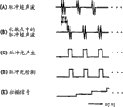
图5是说明与实施例1相关的光学成像装置动作的时序图。 FIG. 5 is a timing chart illustrating the operation of the optical imaging device according to the first embodiment. the
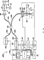
图6是表示与本发明实施例2相关的作为被检体信息分析装置的光学成像装置的整体结构的框图。
6 is a block diagram showing the overall configuration of an optical imaging device as a subject information analysis device related to
图7是表示与实施例2相关的光学成像装置的动作内容的流程图。 FIG. 7 is a flowchart showing the operation content of the optical imaging device according to the second embodiment. the
图8是表示与实施例2的第1变形例相关的光学成像装置的整体结构的框图。 FIG. 8 is a block diagram showing the overall configuration of an optical imaging device according to a first modification of the second embodiment. the
图9是表示与实施例2的第2变形例相关的光学成像装置的整体结构的框图。 9 is a block diagram showing the overall configuration of an optical imaging device according to a second modification of the second embodiment. the
图10是说明与第2变形例相关的光学成像装置的动作的时序图。 FIG. 10 is a timing chart illustrating the operation of the optical imaging device related to the second modification. the
图11是表示实施例2的第3变形例中的透镜保持部以及换能器保持部的结构的图。 FIG. 11 is a diagram showing the configuration of a lens holding portion and a transducer holding portion in a third modification of the second embodiment. the
图12是表示实施例2的第4变形例中的透镜保持部以及换能器保持部的结构的图。 FIG. 12 is a diagram showing the configuration of a lens holding portion and a transducer holding portion in a fourth modification of the second embodiment. the
图13是表示实施例2的第5变形例中的一部分的结构的图。 FIG. 13 is a diagram showing a part of the structure of a fifth modification of the second embodiment. the
图14是表示与本发明实施例3相关的作为被检体信息分析装置的光学成像装置的整体结构的框图。 FIG. 14 is a block diagram showing the overall configuration of an optical imaging device as a subject information analysis device according to Embodiment 3 of the present invention. the
图15是表示光纤端面结构的图。 Fig. 15 is a diagram showing the structure of an optical fiber end face. the
图16是表示光耦合器的结构例的图。 FIG. 16 is a diagram showing a configuration example of an optical coupler. the
图17是表示与实施例3的第1变形例相关的具备光学成像装置的内窥镜装置的结构的框图。 17 is a block diagram showing the configuration of an endoscope device including an optical imaging device according to a first modification of the third embodiment. the
图18是表示实施例3的第2变形例中的内窥镜的前端部附近的结构的图。 Fig. 18 is a diagram showing the structure of the endoscope near the distal end in a second modification of the third embodiment. the
图19是表示实施例3的第3变形例中的光纤结构的立体图。 Fig. 19 is a perspective view showing the structure of an optical fiber in a third modification of the third embodiment. the
图20是表示与本发明的实施例4相关的作为被检体信息分析装置的光学成像装置的整体结构的框图。 20 is a block diagram showing the overall configuration of an optical imaging device as a subject information analysis device according to Embodiment 4 of the present invention. the
图21是实施例4中的从一维扫描得到二维光学成像信息的动作的说明图。 FIG. 21 is an explanatory diagram of the operation of obtaining two-dimensional optical imaging information from one-dimensional scanning in Embodiment 4. FIG. the
图22是表示实施例4的变形例中的超声波/光照射/检测阵列部的概要结构的图。 FIG. 22 is a diagram showing a schematic configuration of an ultrasound/light irradiation/detection array unit in a modified example of Embodiment 4. FIG. the
图23是根据图22的超声波/光照射/检测阵列部的动作的说明图。 FIG. 23 is an explanatory diagram of the operation of the ultrasonic wave/light irradiation/detection array unit shown in FIG. 22 . the
图24是表示与本发明的实施例5~11相关的被检体信息分析装 置的代表性的结构示例的框图。
Fig. 24 is a block diagram showing a representative configuration example of a subject information analysis device according to
图25是表示与本发明的实施例5相关的作为被检体信息分析装置的光学成像装置的整体结构的框图。
25 is a block diagram showing the overall configuration of an optical imaging device as a subject information analysis device according to
图26是在超声波收敛区域附近中进行多普勒频移的样子的说明图。 FIG. 26 is an explanatory diagram of a Doppler shift in the vicinity of an ultrasonic wave convergence region. the
图27是说明与实施例5相关的光学成像装置的动作的流程图。 FIG. 27 is a flowchart illustrating the operation of the optical imaging device according to the fifth embodiment. the
图28是表示进行了傅立叶变换的信号的实数成分的相对角频率的波形例的图。 28 is a diagram showing an example of a waveform of a relative angular frequency of a real number component of a Fourier-transformed signal. the
图29是表示实施例5的第1变形例中的透镜保持部以及换能器保持部构造的图。 Fig. 29 is a diagram showing the structure of a lens holding portion and a transducer holding portion in a first modification of the fifth embodiment. the
图30是实施例5的第2变形例中的超声波收敛点附近区域中进行多普勒频移的样子的说明图。 FIG. 30 is an explanatory view showing how Doppler shift is performed in the vicinity of the ultrasonic wave convergence point in the second modified example of the fifth embodiment. the
图31是表示与本发明的实施例6相关的作为被检体信息分析装置的光学成像装置的整体结构的框图。
31 is a block diagram showing the overall configuration of an optical imaging device as a subject information analysis device according to
图32是表示实施例6的变形例中的透镜保持部以及换能器保持部的结构的图。 FIG. 32 is a diagram showing the configuration of a lens holding portion and a transducer holding portion in a modified example of the sixth embodiment. the
图33是表示与本发明的实施例7相关的作为被检体信息分析装置的光学成像装置的整体结构的框图。
33 is a block diagram showing the overall configuration of an optical imaging device as a subject information analysis device according to
图34是说明与实施例7相关的光学成像装置的动作的流程图。 FIG. 34 is a flowchart illustrating the operation of the optical imaging device according to the seventh embodiment. the
图35是表示进行了傅立叶变换的信号的实数成分的相对角频率的波形例的图。 35 is a diagram showing an example of a waveform of a relative angular frequency of a real number component of a Fourier-transformed signal. the
图36是表示与实施例7的第1变形例相关的光学成像装置的整体结构的框图。 36 is a block diagram showing the overall configuration of an optical imaging device according to a first modification of the seventh embodiment. the
图37是表示与实施例7的第2变形例相关的光学成像装置的整体结构的框图。 37 is a block diagram showing the overall configuration of an optical imaging device according to a second modification of the seventh embodiment. the
图38是表示与本发明的实施例8相关的作为被检体信息分析装置的光学成像装置的整体结构的框图。
38 is a block diagram showing the overall configuration of an optical imaging device as a subject information analysis device according to
图39是说明与实施例8相关的光学成像装置的动作的流程图。 FIG. 39 is a flowchart illustrating the operation of the optical imaging device according to the eighth embodiment. the
图40是表示与实施例8的变形例相关的光学成像装置的整体结构的框图。 FIG. 40 is a block diagram showing the overall configuration of an optical imaging device related to a modification of the eighth embodiment. the
图41是表示与本发明的实施例9相关的作为被检体信息分析装置的光学成像装置的整体结构的框图。 41 is a block diagram showing the overall configuration of an optical imaging device as a subject information analysis device according to Embodiment 9 of the present invention. the
图42是说明与实施例9相关的光学成像装置的动作的时序图。 FIG. 42 is a timing chart illustrating the operation of the optical imaging device according to the ninth embodiment. the
图43是表示与实施例9的第1变形例相关的光学成像装置的整体结构的框图。 43 is a block diagram showing the overall configuration of an optical imaging device according to a first modification of the ninth embodiment. the
图44是表示与实施例9的第2变形例相关的光学成像装置的整体结构的框图。 44 is a block diagram showing the overall configuration of an optical imaging device according to a second modification of the ninth embodiment. the
图45是表示与实施例9的第3变形例相关的光学成像装置的整体结构的框图。 45 is a block diagram showing the overall configuration of an optical imaging device according to a third modification of the ninth embodiment. the
图46是表示与实施例9的第4变形例相关的光学成像装置的一部分结构的框图。 FIG. 46 is a block diagram showing a partial configuration of an optical imaging device according to a fourth modification of the ninth embodiment. the
图47是表示与本发明的实施例10相关的作为被检体信息分析装置的光学成像装置的整体结构的框图。
47 is a block diagram showing the overall configuration of an optical imaging device as a subject information analysis device according to
图48是表示光纤端面结构的图。 Fig. 48 is a diagram showing the structure of an optical fiber end face. the
图49是表示光耦合器的结构例的图。 FIG. 49 is a diagram showing a configuration example of an optical coupler. the
图50是表示与实施例10的第1变形例相关的光学成像装置的整体结构的框图。 FIG. 50 is a block diagram showing the overall configuration of an optical imaging device according to a first modification of the tenth embodiment. the
图51是表示具备与实施例10的第2变形例相关的光学成像装置的内窥镜装置的结构的框图。 51 is a block diagram showing the configuration of an endoscope device including an optical imaging device according to a second modification of the tenth embodiment. the
图52是表示具备与实施例10的第3变形例相关的光学成像装置的内窥镜的前端侧的结构的图。 52 is a diagram showing the configuration of the distal end side of an endoscope equipped with an optical imaging device according to a third modification of the tenth embodiment. the
图53是表示与实施例10的第4变形例中的光纤的结构的立体图。 Fig. 53 is a perspective view showing the configuration of an optical fiber in a fourth modification of the tenth embodiment. the
图54是表示与本发明的实施例11相关的作为被检体信息分析 装置的光学成像装置的结构的框图。
Fig. 54 is a block diagram showing the configuration of an optical imaging device as a subject information analysis device according to
图55是表示与实施例11的第1变形例相关的超声波/光照射/检测阵列部的概要结构的图。 55 is a diagram showing a schematic configuration of an ultrasonic wave/light irradiation/detection array unit related to a first modification of the eleventh embodiment. the
图56是表示与本发明的实施例12~15相关的被检体信息分析装置的基本结构的框图。 Fig. 56 is a block diagram showing the basic configuration of the subject information analysis apparatus according to the twelfth to fifteenth embodiments of the present invention. the
图57是表示与本发明实施例12相关的作为被检体信息分析装置的光学成像装置的整体结构的框图。
Fig. 57 is a block diagram showing the overall configuration of an optical imaging device as a subject information analysis device according to
图58是表示在超声波收敛区域附近进行多普勒频移的样子的图。 FIG. 58 is a diagram showing a Doppler shift in the vicinity of an ultrasonic wave convergence region. the
图59是表示与实施例12相关的光学成像装置的动作内容的流程图。 FIG. 59 is a flowchart showing the operation content of the optical imaging device according to the twelfth embodiment. the
图60是说明与实施例12相关的光学成像装置的动作的时序图。 FIG. 60 is a timing chart illustrating the operation of the optical imaging device according to the twelfth embodiment. the
图61是表示与实施例12的第1变形例相关的可装在光学成像装置中的傅立叶变换电路周边部结构的框图。 Fig. 61 is a block diagram showing the configuration of a peripheral portion of a Fourier transform circuit that can be mounted in an optical imaging device according to a first modification of the twelfth embodiment. the
图62是表示与实施例12的第2变形例相关的光学成像装置的整体结构的框图。 FIG. 62 is a block diagram showing the overall configuration of an optical imaging device according to a second modification of the twelfth embodiment. the
图63是表示与实施例12的第3变形例相关的光学成像装置的整体结构的框图。 FIG. 63 is a block diagram showing the overall configuration of an optical imaging device according to a third modification of the twelfth embodiment. the
图64是表示与本发明的实施例13相关的作为被检体信息分析装置的光学成像装置的整体结构的框图。
Fig. 64 is a block diagram showing the overall configuration of an optical imaging device as a subject information analysis device according to
图65是表示与实施例13相关的光学成像装置的动作内容的流程图。 FIG. 65 is a flowchart showing the operation content of the optical imaging device according to the thirteenth embodiment. the
图66是表示与实施例13的变形例相关的光学成像装置的整体结构的框图。 FIG. 66 is a block diagram showing the overall configuration of an optical imaging device related to a modified example of the thirteenth embodiment. the
图67是表示来自生物体组织的反射光脉冲的大致波形例的图。 Fig. 67 is a diagram showing an example of a rough waveform of a reflected light pulse from a living tissue. the
图68是表示与本发明的实施例14相关的作为被检体信息分析装置的光学成像装置的整体结构的框图。
Fig. 68 is a block diagram showing the overall configuration of an optical imaging device as a subject information analysis device according to
图69是表示光纤端面结构的图。 Fig. 69 is a diagram showing the structure of an optical fiber end face. the
图70是表示光耦合器的结构例的图。 FIG. 70 is a diagram showing a configuration example of an optical coupler. the
图71是表示与实施例14的第1变形例相关的光学成像装置的整体结构的框图。 FIG. 71 is a block diagram showing the overall configuration of an optical imaging device according to a first modification of the fourteenth embodiment. the
图72是表示与实施例14的第2变形例相关的光学成像装置的整体结构的框图。 FIG. 72 is a block diagram showing the overall configuration of an optical imaging device according to a second modification of the fourteenth embodiment. the
图73是表示与本发明的实施例15相关的作为被检体信息分析装置的内窥镜装置的结构的图。
Fig. 73 is a diagram showing the configuration of an endoscope device as a subject information analysis device according to
图74是表示与实施例15的第1变形例相关的内窥镜装置的结构的图。 Fig. 74 is a diagram showing the configuration of an endoscope device according to a first modification of the fifteenth embodiment. the
图75是表示图74中的内窥镜的前端侧的结构的图。 Fig. 75 is a diagram showing the configuration of the distal end side of the endoscope in Fig. 74 . the
图76是表示实施例15的第2变形例中的光纤结构的立体图。 Fig. 76 is a perspective view showing the structure of an optical fiber in a second modification of the fifteenth embodiment. the
具体实施方式 Detailed ways
下面参照附图说明本发明所涉及的被检体信息的分析装置及分析方法的实施例。此外,在这些实施例中的几个实施例中,包含有对内窥镜装置实施了该分析装置的各种实施例。 Embodiments of an analysis device and analysis method of subject information according to the present invention will be described below with reference to the drawings. In addition, some of these embodiments include various embodiments in which the analysis device is implemented on an endoscope device. the
此外,下面说明的各实施例(实施例1~15及其变形例)基于作为与本发明有关的被检体信息分析装置相关的基本结构,即,具有超声波发生部、光发生部、受光部、信息取得部、以及信息生成部,其中,超声波发生部沿空间上期望的轴方向对被检体产生超声波;光发生部朝向前述被检体内的检查部位产生光,该检查部位是从前述超声波发生部产生的前述超声波传达到的检查部位;受光部接受从前述检查部位得到的光,输出与该光对应的信号;信息取得部使用从前述受光部输出的信号或者来自前述检查 部位的光,取得前述检查部位的前述光的散射信息;信息生成部,根据由前述信息取得部取得的信息生成表示前述检查部位特性的信息。
In addition, each of the embodiments described below (
其中,特别地,实施例1~4与如下特征有关,即,前述信息取得部具有相位信息抽出部、散射信息运算部,其中,相位信息抽出部从由前述受光部输出的信号或者来自前述检查部位的光抽出相位信息;散射信息运算部根据由前述相位信息抽出部抽出的相位信息,运算前述检查部位的前述光的散射信息。
Among them, in particular,
另外,实施例5~11与如下特征有关,即,具有频率信息抽出部、散射信息运算单元,其中,频率信息抽出部从由前述受光部输出的信号或者来自前述检查部位的光,抽出前述照明光的多普勒频移的频率信息;散射信息运算单元根据由前述频率信息抽出单元抽出的频率信息运算前述光的散射信息。
In addition,
而且,实施例12~15与如下特征有关,即,前述超声波发生部是脉冲超声波发生部,产生脉冲超声波作为前述超声波,前述光发生部是脉冲照明光发生部,沿光轴产生脉冲照明光,该光轴设定为与对前述被检体发送前述脉冲超声波的前述轴成规定值以下的角度。此时,具有脉冲同步单元,使前述脉冲超声波以及前述脉冲照明光的产生与规定的定时同步。
Furthermore,
在下面的各实施例中,由于记载有多个实施例,因此在各实施例中重视展开良好说明(使得尽量不参照其他实施例也能够理解),将允许部分重复的记载、式以及展开。 In each of the following examples, since a plurality of examples are described, emphasis is placed on well-developed descriptions in each example (so that it can be understood without referring to other examples as much as possible), and partially repeated descriptions, formulas, and developments are allowed. the
实施例1Example 1
参照图1~图5说明实施例1。
图1以框图表示本发明的被检体信息分析装置的基本结构。如图1所示,本发明的被检体信息分析装置具有超声波发生部2、照明光发生部3,其中,超声波发生部2能够产生超声波使得超声波 沿规定的超声波发送轴向被检体内传递;照明光发生部3能够产生照明光,使其到达从前述超声波发生部2发生的前述超声波所传递到的被检体内的检查对象部位。
FIG. 1 shows a block diagram of the basic configuration of the subject information analysis device of the present invention. As shown in Figure 1, the subject information analysis device of the present invention has an
另外,该被检体信息分析装置具有受光部4、信息抽出部5,其中,受光部4配置成朝向前述检查对象部位,使得能够对由照明光发生部3产生的照明光经过了前述检查对象部位的光进行受光;信息抽出部5从基于由该受光部4受光的受光信号的相位信息,抽出前述照明光到达的前述检查对象部位的复折射率中至少与实部相当的信息。
In addition, the subject information analysis device has a light receiving unit 4 and an
信息抽出部5包括相位信息抽出部、散射信息抽出部,其中,相位信息抽出部如在本实施例1等中后述的那样,从由受光部4受光的透过光或散射光(或者反射光)抽出复折射率中至少与实部相当的相位信息;散射信息抽出部从该相位信息抽出散射信息。
The
在图1中,受光部4示出了相当于透过光受光部的配置例(结构例),该透过光受光部将在光轴上透过了被检体的照明光作为观测光进行受光,其中该光轴是来自照明光发生部3的照明光照射到被检体侧的光轴,但不限于此。例如在实施例2中,还有由将反射的光作为观测光进行受光的反射光受光部构成的情况。 In FIG. 1 , the light receiving unit 4 shows an arrangement example (structural example) corresponding to a transmitted light receiving unit that treats, as observation light, illumination light that has passed through the subject on the optical axis. Light is received, wherein the optical axis is the optical axis where the illumination light from the illumination light generating unit 3 is irradiated to the subject side, but is not limited thereto. For example, in Example 2, there may be a case where it is configured by a reflected light receiving unit that receives reflected light as observation light. the
另外,该被检体信息分析装置具有被检体信息生成部6,该被检体信息生成部6根据由前述信息抽出部5抽出的信息,生成与前述照明光所到达的前述检查对象部位对应的前述被检体的特性信息。
In addition, the subject information analysis apparatus includes a subject
该被检体信息生成部6具有图像形成部,该图像形成部用于将例如二维或者三维扫描了被检体的检查对象部位的各位置处的散射信息等进行图像化来显示。
The subject
下面参照图2说明该被检体信息分析装置的更具体的结构。 A more specific configuration of this subject information analysis device will be described below with reference to FIG. 2 . the
图2中示出的实施例1的光学成像装置AP1,作为照明光发生 部3具有产生相干光的例如激光装置3a,该激光装置3a设置在第1单元11a中。此外,作为产生照明光的光源,并不仅限于产生相干光的激光装置3a,也可以使用氙光、卤光等热光源、LED(LightEmitting Diode:发光二极管)、SLD(Super Lumine scant Diode:超辐射发光二极管)。 The optical imaging device AP1 of the first embodiment shown in FIG. 2 has, as the illumination light generating unit 3, a laser device 3a that generates coherent light, for example, and the laser device 3a is provided in the first unit 11a. In addition, as a light source for generating illumination light, it is not limited to the laser device 3a that generates coherent light, thermal light sources such as xenon light and halogen light, LED (Light Emitting Diode: Light Emitting Diode), SLD (Super Lumine Scant Diode: Super Radiation Diode) can also be used. led). the
在该第一单元11a内,内置有构成超声波发生部2的超声波换能器2a。
In this first unit 11a, an ultrasonic transducer 2a constituting the
内置有构成受光部4的光检测器4a等的第二单元11b,与该第一单元11a隔着作为被检体的生物体组织7相对配置。
The second unit 11b incorporating the photodetector 4a constituting the light receiving unit 4 and the like is disposed opposite to the first unit 11a with the
另外,在两个单元11a、11b中,分别安装有扫描单元12a、12b,该扫描单元12a、12b作为扫描部分别对这些单元11a、11b进行二维或三维同步扫描,扫描单元12a、12b根据来自例如设置在控制部8内的扫描信号发生电路24的扫描信号进行动作。
In addition, in the two units 11a, 11b,
在本实施例中,由于构成为使照射光的位置与照射超声波的位置一致,因此作为扫描部,除了扫描作为照明光的激光所照射的位置的照明光扫描部功能的之外,还兼有使该位置也成为超声波照射位置的超声波扫描部的功能。 In this embodiment, since the position where the light is irradiated coincides with the position where the ultrasonic wave is irradiated, as the scanning unit, in addition to the function of the illumination light scanning unit that scans the position irradiated by the laser light as the illumination light, it also serves as the scanning unit. This position is also the function of the ultrasonic scanning unit as the ultrasonic irradiation position. the
而且,如以下所述,设为如下结构:将超声波收敛(收束:会聚)的收敛点F作为检查对象部位,在该收敛点F上存在超声波的定时,由构成受光部4的光检测器4a对基于到达该收敛点F的激光的(进而透过生物体组织7的)透过光进行受光。 Furthermore, as described below, a configuration is adopted in which a point F where ultrasonic waves converge (converge: converge) is used as an inspection target site, and the timing when ultrasonic waves exist at this convergent point F is determined by the photodetector constituting the light receiving unit 4. 4 a receives light transmitted by the laser light that has reached the converging point F (further transmitted through the living tissue 7 ). the
也就是说,在本实施例中设置有控制电路25,该控制电路25控制扫描信号发生电路24等,使得移动(扫描)第1单元11a使其位置改变,并且在该位置变化的情况下也能够由构成受光部4的光检测器4a对来自该位置的光进行受光。由此能够取得不同的检查对象部位的散射信息进行图像化。
That is, in this embodiment, a
如图2所示,在将超声波在生物体组织7内行进的方向设为z 轴的情况下,扫描单元12a、12b在例如x、y方向(在图2中以符号A、B表示)上二维扫描两个单元11a、11b。此外,扫描单元12a、12b也可以不是x、y方向,而是x、z方向或y、z方向。或者也可以设为x、y、z三维扫描那样的结构。
As shown in FIG. 2, when the direction in which ultrasonic waves travel in the
另外,由设置在第二单元11b内的、构成受光部4的光检测器4a进行了光电变换后的电信号,被输入到构成信息抽出部5中的相位信息抽出部的示波器5a中。该示波器5a从电信号中抽出复折射率的相位成分,并输出到构成被检体信息生成部6(的图像形成部)的个人计算机6a中。
In addition, the electric signal photoelectrically converted by the photodetector 4a constituting the light receiving unit 4 provided in the second unit 11b is input to the oscilloscope 5a constituting the phase information extracting unit of the
来自第一单元11a内的激光装置3a的激光,通过具有作为分光器功能的半透射半反射镜13a分为透过光和反射光,透过的激光被反射镜14a反射后,通过构成超声波发生部2的超声波换能器2a的开口15照射到生物体组织7侧。
The laser light from the laser device 3a in the first unit 11a is divided into transmitted light and reflected light by the semi-transmissive half-reflector 13a having the function of a beam splitter. The
该超声波换能器2a通过将脉冲状超声波驱动信号施加到设置在超声波换能器主体上的电极上而产生脉冲状超声波,该超声波换能器例如由压电元件构成并具有电声变换功能,而该脉冲状超声波驱动信号来自设置在控制部8内的脉冲发生器21并由功率放大器22进行了放大。
The ultrasonic transducer 2a generates a pulsed ultrasonic wave by applying a pulsed ultrasonic drive signal to an electrode provided on the ultrasonic transducer body. The ultrasonic transducer is, for example, made of a piezoelectric element and has an electroacoustic conversion function. On the other hand, the pulsed ultrasonic driving signal comes from a
在本实施例中,超声波换能器2a通过脉冲发生器21以及功率放大器22形成产生脉冲状超声波的脉冲超声波发生部。
In the present embodiment, the ultrasonic transducer 2 a forms a pulsed ultrasonic wave generator that generates pulsed ultrasonic waves through a
此外,也可以通过将来自脉冲发生器21并由功率放大器22放大后的超声波驱动信号,设为连续波形状而不是脉冲形状,而使超声波换能器2a产生连续超声波。
In addition, the ultrasonic transducer 2a may generate continuous ultrasonic waves by making the ultrasonic drive signal from the
另外,此时,作为来自脉冲发生器21的其它信号,与连续超声波的疏密间隔相应的、也就是与超声波的波长相应的脉冲状信号经过延迟电路23被作为参考信号输入到示波器5a进行同步检波,由此也可以得到与照射脉冲状超声波的情况相同的效果。
In addition, at this time, as other signals from the
上述超声波换能器2a,在超声波发射面侧安装了收敛超声波的作为超声波收敛部的声音透镜16。
The above-mentioned ultrasonic transducer 2a is equipped with an
在本实施例中,沿该声音透镜16的超声波发送轴(也称为音轴)Ou设置有开口15,透过半透射半反射镜13a并被反射镜14a反射的激光,通过该开口15沿超声波的超声波发送轴Ou行进到生物体组织7内。
In this embodiment, an
此外,在本实施例中声音透镜16接触生物体组织7表面,但是也可以通过传递超声波的介质将超声波传递到生物体组织7的表面。
In addition, in the present embodiment, the
然后,从超声波换能器2a传递到生物体组织7侧的超声波,在以与声音透镜16的焦点距离相当的收敛点F为中心的附近区域R1中收敛。
Then, the ultrasonic waves transmitted from the ultrasonic transducer 2 a to the
在图2或者图3中以虚线表示该附近区域R1。 The vicinity region R1 is indicated by a dotted line in FIG. 2 or FIG. 3 . the
局限于该收敛点F的附近区域R1中的超声波,引起构成该附近区域R1中的生物体组织7的分子的密度变化Δρ(z)(后述)。
Ultrasonic waves localized in the region R1 near the convergence point F cause a density change Δρ(z) (described later) of molecules constituting the
将基于此的调制光作为观测光,由光检测器4a进行检测。 The modulated light based on this is detected by the photodetector 4a as observation light. the
另一方面,被半透射半反射镜13a反射的激光,通过被振荡器17的振荡输出所驱动的光调制器18后,被配置在其前方侧的参照反射镜14b反射后,作为参照光入射到用于混合(干涉)的半透射半反射镜13b。
On the other hand, the laser light reflected by the half mirror 13a passes through the
配置在上述半透射半反射镜13a以及参照反射镜14b之间的光调制器18,由例如LiNbO3等具有光电效应的铁电晶体构成,通过施加振荡器17的振荡频率的交流电场,其折射率与该施加的电场成比例变化。
The
因而,通过了该铁电晶体的激光将被光调制。也就是说,当将光调制器18的光调制中使用的振荡器17的角频率设为ω’o时,被半透射半反射镜13a反射的激光以该角频率ω’o被进行光调制。
Thus, laser light passing through the ferroelectric crystal will be optically modulated. That is, when the angular frequency of the
此外,振荡器17的角频率ω’o是远远低于激光的角频率的频率,设定为容易进行信号处理的频率。
In addition, the angular frequency ω'o of the
在上述超声波发送轴Ou上,在相对于生物体组织7与开口15相反的一侧配置有遮光部件19的开口19a。并且,被反射镜14a反射并通过了生物体组织7内的附近区域R 1的激光,通过该开口19a入射到配置在其行进方向前方的半透射半反射镜13b。该开口19a,使通过了收敛点F的附近区域R1的光作为观测光通过,抑制(排除)其周围的漫射光成分。
The opening 19 a of the
在附近区域R1中散射的观测光、和进行了光调制的参照光都入射到上述半透射半反射镜13b中,这两种光通过该干涉用半透射半反射镜13b进行光混合、或者干涉。
Both the observation light scattered in the vicinity region R1 and the light-modulated reference light are incident on the
也就是说,以频率ω’o进行了光调制后的参照光、和通过了生物体组织7的收敛点F的附近区域R1的透过了生物体组织7的观测光,都入射到该半透射半反射镜13b中,并被进行光混合而生成以角频率ω’o进行了光调制的干涉光(或者差拍信号光)。(也就是说,成为进行了外差检波的光)。
That is, both the reference light modulated at the frequency ω'o and the observation light passing through the
生成的干涉光由光检测器4a受光,检测出作为电信号的干涉信号(差拍信号)。此外,由光检测器4a进行光电变换后,能够使用使角频率ω’o的差拍成分通过的LPF等来抽出干涉信号成分。由此在本实施例中,采用马赫-曾德干涉计的结构。 The generated interference light is received by the photodetector 4 a to detect an interference signal (beat signal) as an electrical signal. In addition, after photoelectric conversion is performed by the photodetector 4a, an interference signal component can be extracted using an LPF or the like that passes the beat component of the angular frequency ω'o . Therefore, in this embodiment, the structure of the Mach-Zehnder interferometer is adopted.
由上述光检测器4a检测出的干涉信号,被输入到具有进行相位信息抽出的相位计功能的示波器5a中,检测附近区域R1中的激光的相位调制成分以及振幅调制成分。 The interference signal detected by the photodetector 4a is input to an oscilloscope 5a having a phase meter function for extracting phase information, and the phase modulation component and the amplitude modulation component of the laser light in the nearby region R1 are detected. the
相位调制成分以及振幅调制成分,如后所述,是分别与复折射率的实部和虚部对应的成分,是反映了附近区域R1的散射特性和吸收特性的成分。 As will be described later, the phase modulation component and the amplitude modulation component correspond to the real part and the imaginary part of the complex refractive index, respectively, and reflect the scattering characteristics and absorption characteristics of the nearby region R1. the
此外,将示波器5a作为相位计,能够检测相位调制成分和振 幅调制成分,但是也可以设为在PC6a侧通过傅立叶变换处理来检测它们。 In addition, the phase modulation component and the amplitude modulation component can be detected by using the oscilloscope 5a as a phase meter, but they may also be detected by Fourier transform processing on the PC 6a side. the
在本实施例中,也可以构成为由PC6a侧算出与复折射率的实部以及虚部对应的相位调制成分以及振幅调制成分。在这种情况下,PC6a除了被检体信息生成部6的功能之外,还兼有相位信息抽出部以及散射信息抽出部的功能。
In this embodiment, it is also possible to configure the phase modulation component and the amplitude modulation component corresponding to the real part and the imaginary part of the complex refractive index from the PC6a side. In this case, the PC 6 a also functions as a phase information extraction unit and a scattering information extraction unit in addition to the function of the subject
在这种情况下,干涉信号如虚线所示,也输入到PC6a中。另外,在这种情况下,CPU33如虚线所示,具有从干涉信号算出实部和虚部的实部以及虚部算出部33a。 In this case, the interference signal is also input to the PC 6a as indicated by the dotted line. In addition, in this case, the CPU 33 has a real part and imaginary part calculation unit 33 a that calculates a real part and an imaginary part from the interference signal, as indicated by a dotted line. the
为了检测照射到生物体组织7中的关注的附近区域R1的激光的透过光、抽出该附近区域R1中的至少相位调制成分(也就是复折射率的实部成分)的信息,脉冲发生器21的输出经过能够调整延迟量的延迟电路23输入到示波器5a,进而还输入到PC6a。
In order to detect the transmitted light of the laser light irradiated to the nearby region R1 of interest in the
另外,在本实施例中,为了得到(至少包含一维的)二维光学成像信息,具有例如与脉冲发生器21的输出同步产生扫描信号的扫描信号发生电路24。
In addition, in this embodiment, in order to obtain (at least one-dimensional) two-dimensional optical imaging information, there is, for example, a scanning
脉冲发生器21、延迟电路23以及扫描信号发生电路24,被由未图示的CPU等构成的控制电路25控制。
The
通过示波器5a检测出的相位调制成分以及振幅调制成分的输出信号和扫描信号,输入到PC6a的A/D变换电路31,被变换为数字信号后存储到存储器32中。
The output signal and scanning signal of the phase modulation component and the amplitude modulation component detected by the oscilloscope 5 a are input to the A/
另外,如图2中虚线所示,在将干涉信号不通过示波器5a而保存在存储器32中的情况下,CPU33进行图像处理,算出与上述附近区域R 1中的激光的相位(调制)成分以及振幅(调制)成分分别对应的复折射率的实部以及虚部。 In addition, as shown by the dotted line in FIG. 2, when the interference signal is stored in the memory 32 without passing through the oscilloscope 5a, the CPU 33 performs image processing to calculate the phase (modulation) component and The amplitude (modulation) components correspond to the real and imaginary parts of the complex refractive index, respectively. the
该CPU33将进行了图像处理的结果的信号数据与位置信息相关联存储到存储器32,经过显示处理电路34输出到监视器35,在 该监视器35的显示面中将相位成分以及振幅成分的二维光学成像信息作为被检体特性信息进行显示。
The CPU 33 stores the signal data of the result of the image processing in association with the position information in the memory 32, outputs it to the
存储器32将作为构成图像形成部的CPU33的图像形成信息的相位成分等与位置信息相关联进行存储。 The memory 32 stores, in association with position information, phase components, etc., which are image formation information of the CPU 33 constituting the image formation unit. the
示波器5a作为相位计发挥作用,即,按照脉冲发生器21的同步信号抽出振幅调制成分或者相位调制成分(后述的式(10)的第2项中的相位成分)。
The oscilloscope 5 a functions as a phase meter, that is, extracts an amplitude modulation component or a phase modulation component (phase component in the second term of Equation (10) described later) according to the synchronization signal of the
另外,脉冲发生器21以例如与该调制信号同步的定时、例如以该调制信号的整数倍周期产生脉冲状超声波驱动信号。
In addition, the
另外,PC6a的A/D变换电路31,以与该调制信号同步的时钟进行A/D变换(更具体地说,A/D变换电路31与该调制信号同步,按照以其整数倍的角频率振荡的未图示时钟振荡器的时钟进行A/D变换)。然后,将进行了A/D变换的数据保存在存储器32中。
In addition, the A/
参照图4以及图5说明根据这种结构的本实施例的动作。 The operation of this embodiment with such a configuration will be described with reference to FIGS. 4 and 5 . the
当本实施例的光学成像装置AP1的电源接通时,或按下测定开始的开关等时,如图4的步骤S1所示,激光装置3a产生激光。如图5(A)所示,该激光连续产生。 When the optical imaging device AP1 of this embodiment is powered on, or when a measurement start switch is pressed, as shown in step S1 of FIG. 4 , the laser device 3a generates laser light. As shown in Fig. 5(A), the laser light is generated continuously. the
另外,如步骤S2所示,通过超声波换能器2a,以固定周期产生脉冲状的超声波。在此,控制电路25向脉冲发生器21发送控制信号,如图5(B)所示,脉冲发生器21以固定周期T产生驱动超声波换能器2a的脉冲状超声波驱动信号。
In addition, as shown in step S2, pulsed ultrasonic waves are generated at a fixed cycle by the ultrasonic transducer 2a. Here, the
通过上述超声波驱动信号的施加,由超声波换能器2a产生的脉冲状超声波,由声音透镜16收敛的同时传输到生物体组织7内。然后,该脉冲超声波将在以收敛点F为中心的其附近区域R1中收敛。
By the application of the ultrasonic drive signal, the pulsed ultrasonic waves generated by the ultrasonic transducer 2 a are transmitted into the
另一方面,如步骤S3所示,通过激光装置3a产生的激光由半透射半反射镜13a分支。 On the other hand, as shown in step S3, the laser light generated by the laser device 3a is branched by the half mirror 13a. the
然后,如步骤S4所示,朝向参照反射镜14b的激光被光调制器18调制后,由参照反射镜14b反射并入射到半透射半反射镜13b中。
Then, as shown in step S4, the laser light directed toward the reference mirror 14b is modulated by the
另一方面,如步骤S4b所示,朝向反射镜14a侧的激光,被该反射镜14a反射后,照射到生物体组织7内部。
On the other hand, as shown in step S4b, the laser beam directed toward the reflection mirror 14a side is reflected by the reflection mirror 14a, and then irradiates the inside of the
如上所述,在生物体组织7内传输的超声波在以收敛点F为中心的其附近区域R1中收敛。因此,照射到生物体组织7内部的激光,特别在该附近区域R1中接受由超声波引起的复折射率变化的调制。然后,该调制光经过开口19a入射到半透射半反射镜13b中。
As described above, the ultrasonic waves propagating through the
然后,如步骤S5所示,参照光和观测光(物体光)在该半透射半反射镜13b上进行干涉。
Then, as shown in step S5, the reference light and the observation light (object light) interfere on the
如步骤S6所示,该干涉光由光检测器4a受光,并变换为电信号后,例如通过LPF等成为进行了外差检波的干涉信号。 As shown in step S6, the interference light is received by the photodetector 4a, converted into an electrical signal, and then converted into an interference signal subjected to heterodyne detection by, for example, an LPF or the like. the
在接着的步骤S7中,该干涉信号通过该示波器5a从干涉信号检测相位成分以及振幅(在附图中简记为相位成分等)。此外,也可以使用锁定放大器代替示波器5a从干涉信号抽出相位成分等。 In the next step S7, the phase component and the amplitude of the interference signal are detected from the interference signal by the oscilloscope 5a (abbreviated as phase component and the like in the drawings). In addition, a lock-in amplifier may be used instead of the oscilloscope 5a to extract a phase component or the like from the interference signal. the
上述控制电路25进行控制,使得延迟电路23的延迟量成为从脉冲状超声波驱动信号的产生时刻到脉冲超声波到达收敛点F的时刻为止的时间(在图5(C)中以Tf表示)。
The
然后,通过该延迟电路23延迟的脉冲输入到示波器5a,在该定时,如图5(c)所示,示波器5a在其内部产生选通脉冲。
Then, the pulse delayed by the
该示波器5a,在选通脉冲期间内产生与来自振荡器17的ω’o的调制信号同步的扫描信号,将该扫描信号作为水平方向的时基,将由光检测器4a检测出的信号值作为纵坐标显示。
The oscilloscope 5a generates a scan signal synchronized with the modulation signal of ω'o from the
也就是说,以角频率ω’o的调制信号的周期为基准,能够检测出由光检测器4a检测出的干涉信号中的任意相位角的信号成分。另外,还能够检测振幅成分。 That is, it is possible to detect a signal component at an arbitrary phase angle in the interference signal detected by the photodetector 4 a based on the period of the modulation signal of the angular frequency ω′ o . In addition, amplitude components can also be detected.
而且,示波器5a在该选通脉冲期间、也就是脉冲超声波到达收敛点F的时刻附近的短期间中,从光检测器4a输出的干涉信号检测其相位成分和振幅成分。 Then, the oscilloscope 5 a detects the phase component and the amplitude component of the interference signal output from the photodetector 4 a during the gate pulse period, that is, a short period near the time when the pulsed ultrasonic wave reaches the convergence point F. the
另外,通过示波器5a检测的相位成分以及振幅成分,输入到PC6a内,由A/D变换电路31变换为数字信号数据。然后,如步骤S8所示,作为光学成像信息保存到作为PC6a内的信息存储单元的例如存储器32中。
In addition, the phase component and the amplitude component detected by the oscilloscope 5 a are input into the PC 6 a and converted into digital signal data by the A/
此外,PC6a从输入的干涉信号除了检测相位成分之外,也检测其振幅成分并作为光学成像信息保存到存储器32中。 In addition, the PC 6a detects not only the phase component but also the amplitude component of the input interference signal, and stores it in the memory 32 as optical imaging information. the
另外,该光学成像信息与扫描信号、也就是收敛点F的二维位置信息(x,y)甚至三维位置信息(x,y,z)相关联保存到存储器32中。 In addition, the optical imaging information is stored in the memory 32 in association with the scanning signal, that is, the two-dimensional position information (x, y) or even the three-dimensional position information (x, y, z) of the convergence point F. the
在图5(D)中通过相位成分以及振幅成分抽出来示意性地表示出如上述那样,在超声波存在于收敛点F的附近区域R1的短期间内,将从干涉信号经过示波器5a检测出的相位成分和振幅成分的数据存储到PC6a内的情况。在这种情况下,由示波器5a检测后述的式(11)的第2项并保存。在示波器5a中,将ω’o的周期作为时基(相位基准),从例如超声波尚未收敛的状态下的干涉信号的波形检测超声波收敛后的时间轴方向的频移量和振幅变化量。 Fig. 5(D) schematically shows the phase component and the amplitude component extracted from the interference signal detected by the oscilloscope 5a during the short period when the ultrasonic wave exists in the region R1 near the convergence point F as described above. When the data of phase component and amplitude component are stored in PC6a. In this case, the second term of the formula (11) described later is detected and stored by the oscilloscope 5a. The oscilloscope 5a uses the cycle of ω'o as a time base (phase reference), and detects the amount of frequency shift and amplitude change in the time axis direction after the ultrasonic wave has converged, for example, from the waveform of the interference signal in a state where the ultrasonic wave has not yet converged.
在下面的步骤S9中,控制电路25进行是否是扫描终端的判断。而且在不是终端的情况下,如步骤S10所示,控制电路25控制扫描信号发生电路24的动作,移动超声波的收敛点F。
In the next step S9, the
在这种情况下,控制电路25使来自扫描信号发生电路24的扫描信号的振幅变化1个步幅。该扫描信号发生电路24,例如产生台阶状或者锯齿状扫描信号。
In this case, the
扫描信号发生电路24,例如使扫描信号中的振幅值变化例如1/256。图5(E)表示例如x方向的扫描信号的例子。
The scan
扫描单元12a、12b通过该扫描信号将两个单元11a、11b向x方向移动微小距离。
The
然后返回到步骤S2,重复同样的处理。并且从x方向的扫描范围的始点到终端为止重复进行同样的处理之后,这次使y方向的扫描信号振幅变换1个步幅。然后,从x方向的始点到终端同样地进行移动。 Then return to step S2 and repeat the same process. Then, after repeating the same process from the start point to the end of the scan range in the x direction, the amplitude of the scan signal in the y direction is converted by one step this time. Then, the same movement is performed from the start point to the end point in the x direction. the
通过重复这种处理,从x、y的扫描范围的始点到终端,扫描单元12a、12b在通过扫描信号移动两个单元11a、11b的同时取得图像信息。
By repeating such processing, the
然后当在步骤S9中判断为是扫描终端时,进入到步骤S11,完成光学成像信息的图像生成。然后进行光学成像信息的图像显示,结束该动作。 Then, when it is determined in step S9 that it is a scanning terminal, go to step S11 to complete image generation of optical imaging information. Then, the image display of the optical imaging information is performed, and this operation ends. the
此外,在使用连续超声波的情况下,也能够大致与图4同样实施,但是在该情况下需要变更步骤S2的部分,使得产生收敛的连续超声波。 In addition, when continuous ultrasonic waves are used, it can be carried out substantially in the same manner as in FIG. 4 , but in this case, it is necessary to change the part of step S2 so that converging continuous ultrasonic waves are generated. the
下面说明由PC6a进行的光学成像信息的图像显示。 Next, image display of optical imaging information by the PC 6a will be described. the
如上所述,在PC6a内的存储器32中,保存了1帧的各信号数据中的相位成分和振幅成分。相位成分和振幅成分,分别与复折射率的实部和虚部对应,反映散射特性和吸收特性。 As described above, the phase component and the amplitude component in each signal data of one frame are stored in the memory 32 in the PC 6a. The phase component and the amplitude component correspond to the real part and the imaginary part of the complex refractive index, respectively, and reflect the scattering and absorption properties. the
而且,CPU33读出与位置信息相关联保存在存储器32中的相位成分和振幅成分,并发送到显示处理电路34。显示处理电路34,将各位置的相位成分值、振幅值例如变换为亮度水平来输出到监视器35中,收敛点F的附近区域R1中的基于相位成分的散射特性和基于振幅成分的吸收特性的光学成像信息被图像化显示在监视器35中。
Then, the CPU 33 reads out the phase component and the amplitude component stored in the memory 32 in association with the position information, and sends it to the display processing circuit 34 . The display processing circuit 34 converts the phase component value and the amplitude value at each position, for example, into a luminance level and outputs it to the
下面说明通过CPU33进行从干涉信号算出散射成分(实部)以及吸收成分(虚部)的动作。 Next, the operation of calculating the scattering component (real part) and the absorption component (imaginary part) from the interference signal by the CPU 33 will be described. the
在超声波局限的如脉冲超声波的收敛点F的附近区域R1那样的、生物体组织7中的狭窄区域中,动态地引起构成该介质的分子的密度变化Δρ(z)。
In a narrow region in the
当将Lorentz-Lorenz的关系式用分子密度进行一次微分时,复折射率m的复折射率变化Δm(z)和密度变化Δρ(z),由下式表示。 When the Lorentz-Lorenz relationship is firstly differentiated by the molecular density, the complex refractive index change Δm(z) and the density change Δρ(z) of the complex refractive index m are expressed by the following formula. the
Δm=(A/W)(m2+2)2Δρ/(6m) (1) Δm=(A/W)(m 2 +2) 2 Δρ/(6m) (1)
在此,W是构成介质的分子的分子量,A是每1mol的全极化率。 Here, W is the molecular weight of molecules constituting the medium, and A is the total polarizability per 1 mol. the
由于如上述(1)式那样复折射率m发生变化,通过超声波收敛点F的附近区域R1的光,与由于超声波而发生了复折射率变化的介质部分相互作用,在该部分中被散射以及吸收。 Since the complex refractive index m changes as in the above formula (1), the light passing through the region R1 near the ultrasonic wave convergence point F interacts with the medium part where the complex refractive index changes due to the ultrasonic wave, and is scattered and absorb. the
当将向生物体组织7入射的入射光、也就是激光的角频率设为ωs、其波数设为ks、从生物体组织7(介质)表面到超声波收敛点F为止的深度设为z(参照放大了图2一部分的放大图3)、真空下的光的波数设为ko时,通过生物体组织7的电场Es(z,t)能够以下式(2)近似。
When the incident light incident on the
Es(z,t)≡Es=Esoexp{i(ωst-ksz)} (2) E s (z, t)≡E s =E so exp{i(ω s tk s z)} (2)
另一方面,光的光路长度z成为下式(3)。 On the other hand, the optical path length z of light becomes the following formula (3). the
z=D0+D1+L2+m(L3-Δz)+L4+(m+Δm)Δz=D0+D1+L2+L4+mL3+ΔmΔz (3) z=D 0 +D 1 +L 2 +m(L 3 -Δz)+L 4 +(m+Δm)Δz=D 0 +D 1 +L 2 +L 4 +mL 3 +ΔmΔz (3)
在此,如图2所示,D0表示激光装置3a和半透射半反射镜13a间的距离,D1表示半透射半反射镜13a和反射镜14a(或参照反射镜14b和半透射半反射镜13b)间的距离,L1表示半透射半反射镜13a和反射镜14b间的距离,L2表示反射镜14a和(激光沿超声波发送轴Ou入射的位置的)生物体组织7的表面间的距离,L3表示在超声波发送轴Ou上的生物体组织7的厚度,L4表示从生物体组织7的底面 到半透射半反射镜13b为止的距离。将超声波的收敛点F的附近区域R1(以下简记为超声波收敛区域)中的复折射率作为包含了该变化量的m+Δm定义为:
Here, as shown in FIG. 2, D 0 represents the distance between the laser device 3a and the half mirror 13a, and D 1 represents the distance between the half mirror 13a and the mirror 14a (or refer to the distance between the mirror 14b and the half mirror 14a). The distance between the
m+Δm=(mr+Δmr)-i(mi+Δmi)=(mr-imi)+(Δmr-iΔmi) (4) m+Δm=(m r +Δm r )-i(m i +Δm i )=(m r -im i )+(Δm r -iΔm i ) (4)
将式(3)代入式(2)时,可以写为下式(5)那样。 When formula (3) is substituted into formula (2), it can be written as the following formula (5). the
Es=Esoexp{i(ωst-ksz)}=Esoexp[i{ωst-ko(D0+D1+L2+L4+mL3+Δ E s =E so exp{i(ω s tk s z)}=E so exp[i{ω s tk o (D 0 +D 1 +L 2 +L 4 +mL 3 +Δ
mΔz)}] (5) mΔz)}] (5)
将(4)的关系式代入式(5)并整理,能够记述为下式(6)。 By substituting the relational expression of (4) into the expression (5) and arranging it, it can describe as following expression (6). the
Es=Esoexp[i{ωst-ko(D0+D1+L2+L4+(mr-imi)L3+(Δmr-iΔmi)Δ E s =E so exp[i{ω s tk o (D 0 +D 1 +L 2 +L 4 +(m r -im i )L 3 +(Δm r -iΔm i )Δ
z)}] z)}]
=Esoexp[iωst-iko(D0+D1+L2+L4+mrL3+ΔmrΔz)]exp{iko(imi)L3 =E so exp[iω s t-ik o (D 0 +D 1 +L 2 +L 4 +m r L 3 +Δm r Δz)]exp{ik o (im i )L 3
+iko(iΔmi)Δz} +ik o (iΔm i )Δz}
=Esoexp[-ko(miL3+ΔmiΔz)]exp[i{ωst-ko(D0+D1+L2+L4+mrL3+ =E so exp[-k o (m i L 3 +Δm i Δz)]exp[i{ω s tk o (D 0 +D 1 +L 2 +L 4 +m r L 3 +
ΔmrΔz)}] (6) Δm r Δz)}] (6)
该式(6)当超声波收敛部位的介质的复折射率m+Δm的实部(也就是mr+Δmr)和虚部(也就是mi+Δmi)都变化时,通过该超声波收敛部位的透过光或者散射光的相位项和振幅项分别局部地接受调制。 In this formula (6), when both the real part (that is, m r +Δm r ) and the imaginary part (that is, m i +Δm i ) of the complex refractive index m+Δm of the medium at the point where the ultrasonic wave converges changes, the ultrasonic wave converges The phase term and the amplitude term of the transmitted light or scattered light of the site are locally modulated, respectively.
并且,在本实施例中,通过这样抽出来自超声波收敛区域的介质的透过光等中的局部相位调制成分和振幅调制成分,得到该介质内部的局部散射特性和吸收特性。 Furthermore, in this embodiment, by extracting the local phase modulation component and the amplitude modulation component in the transmitted light or the like from the medium in the ultrasonic wave converging region in this way, the local scattering characteristics and absorption characteristics inside the medium are obtained. the
在此,复折射率m+Δm的虚部(mi+Δmi)是表示光吸收的量,也称为消光系数,与吸收系数α有下式(7)的关系。 Here, the imaginary part (m i +Δm i ) of the complex refractive index m+Δm represents the amount of light absorption, is also called the extinction coefficient, and has the following relationship with the absorption coefficient α in the following formula (7).
α=4πmi/λ (7) α=4πm i /λ (7)
该吸收系数α,与输入光的强度减小到1/e的传输距离的倒数相当。根据(6)式以及(7)式通过抽出超声波的振幅调制成分,能够间接地算出超声波收敛区域的吸收系数α。 This absorption coefficient α corresponds to the reciprocal of the transmission distance at which the intensity of the input light is reduced to 1/e. The absorption coefficient α of the ultrasonic wave convergence region can be calculated indirectly by extracting the amplitude modulation component of the ultrasonic wave from the expressions (6) and (7). the
在本实施例中,能够将散射特性以及吸收特性作为图像来取得,但是如以下所说明的那样,大的特征是特别是能够取得散射特性。 In the present embodiment, the scattering characteristics and the absorption characteristics can be obtained as images, but as described below, the major feature is that the scattering characteristics can be obtained in particular. the
一般,伴随肿瘤的癌化的核内染色体的浓缩状态、核内空间分布变化等的组织构造变化,引起折射率分布的变化。另一方面,散射强度分布反映复折射率的实部mr(在Mie散射理论中,周围介质和散射体的折射率的实部是决定散射波形的参数)。 In general, changes in the refractive index distribution are caused by changes in the histological structure such as the concentration state of chromosomes in the nucleus and changes in the spatial distribution in the nucleus accompanying canceration of tumors. On the other hand, the scattering intensity distribution reflects the real part m r of the complex refractive index (in the Mie scattering theory, the real part of the refractive index of the surrounding medium and the scatterer is a parameter that determines the scattering waveform).
因而从式(6)可知,折射率变化Δmr与观测光中的相位调制成分相当,因此如果能够通过外差检波检测该相位变化,则能够观测与超声波收敛区域的复折射率实部的变化、即与有关癌组织的组织构造变化相关的散射特性。 Therefore, it can be seen from equation (6) that the refractive index change Δm r is equivalent to the phase modulation component in the observation light, so if the phase change can be detected by heterodyne detection, the change of the real part of the complex refractive index in the ultrasonic convergence region can be observed , that is, the scattering properties related to the histological changes of the cancerous tissue.
在式(6)中,表示了直接检测使入射光入射到生物体组织7并通过超声波收敛区域透过生物体组织7的透过光(即观测光)的情况,仅仅如此难以用良好的S/N检测相位成分。
In Equation (6), the case of directly detecting the incident light incident on the
因此,如图2所示,进行抽出干涉光(差拍信号光)的外差检波,该干涉光是通过由半透射半反射镜13b将由光调制器18进行了光调制的参照光、和通过超声波收敛区域的观测光进行光混合并干涉得到的。由光检测器4a对与该外差检波相当的干涉光进行受光,得到干涉信号。
Therefore, as shown in FIG. 2 , heterodyne detection is performed to extract the interference light (beat signal light) that passes through the
也就是说,作为来自超声波收敛区域的观测光,将由(6)式表示的电场成分的光入射到光检测器4a中,与此相对,通过参照反射镜14b反射的由下式(8)表示的电场成分的参照光也入射到光检测器4a中。 That is, as the observation light from the ultrasonic wave converging region, the light having the electric field component represented by the formula (6) is incident on the photodetector 4a, while the light reflected by the reference mirror 14b is represented by the following formula (8). The reference light of the electric field component is also incident on the photodetector 4a. the
Er=Eroexp[i{(ωs-ω’o)t-ko(D0+L1+D1)}] (8) E r =E ro exp[i{(ω s -ω' o )tk o (D 0 +L 1 +D 1 )}] (8)
能够由光检测器4a检测出的是式(6)和式(8)的和的平方的时间积分,为了简单起见,设为 What can be detected by photodetector 4a is the time integral of the square of the sum of formula (6) and formula (8), for the sake of simplicity, set as
Es=E’sexp{i(ωst+φ1)},Er=E’rexp[i{(ωs-ω’o)t+φ2}] 时, When E s =E' s exp{i(ω s t+φ 1 )}, E r =E' r exp[i{(ω s -ω' o )t+φ 2 }],
E=Es+Er E= Es + Er
={E’sexp(iφ1)+E’rexp(-iω’ot+φ2)}exp(iωst)I(z,t)=|E2|=|EE*| ={E' s exp(iφ 1 )+E' r exp(-iω' o t+φ 2 )}exp(iω s t)I(z, t)=|E 2 |=|EE * |
=[E’sexp(iφ1)+E’rexp{-i(ω’ot-φ2)}]exp(iωst) =[E' s exp(iφ 1 )+E' r exp{-i(ω' o t-φ 2 )}]exp(iω s t)
×[E’sexp(-iφ1)+E’rexp{i(ω’ot-φ2)}]exp(-iωst) ×[E' s exp(-iφ 1 )+E' r exp{i(ω' o t-φ 2 )}]exp(-iω s t)
=E’s 2+E’r 2+E’sE’rexp(iφ1) =E' s 2 +E' r 2 +E' s E' r exp(iφ 1 )
exp{i(ω’ot-φ2)}+E’sE’rexp(-iφ1)exp{-i(ω’ot-φ2)} exp{i(ω' o t-φ 2 )}+E' s E' r exp(-iφ 1 )exp{-i(ω' o t-φ 2 )}
=E’s 2+E’r 2+E’sE’rexp{i(ω’ot-φ2+φ1)}+E’sE’rexp{-i(ω’ot-φ2+φ1)} =E' s 2 +E' r 2 +E' s E' r exp{i(ω' o t-φ 2 +φ 1 )}+E' s E' r exp{-i(ω' o t- φ 2 +φ 1 )}
=E’s 2+E’r 2+2E’sE’rcos(ω’ot-φ2+φ1) (9) =E' s 2 +E' r 2 +2E' s E' r cos(ω' o t-φ 2 +φ 1 ) (9)
在此, here,
E’s=Esoexp{-ko(miL3+ΔmiΔz)},E’r=Ero E' s =E so exp{-k o (m i L 3 +Δm i Δz)}, E' r =E ro
另外, in addition,
φ1=-ko(D0+D1+L2+L4+mrL3+ΔmrΔz),φ2=-ko(D0+D1+L1) φ 1 =-k o (D 0 +D 1 +L 2 +L 4 +m r L 3 +Δm r Δz), φ 2 =-k o (D 0 +D 1 +L 1 )
因此式(9)为 So formula (9) is
I(z,t) I(z,t)
=|Esoexp{-ko(miL3+ΔmiΔz)}|2+|Ero|2+2EsoEroexp{-ko(miL3+ΔmiΔz)} =|E so exp{-k o (m i L 3 +Δm i Δz)}| 2 +|E ro | 2 +2E so E ro exp{-k o (m i L 3 +Δm i Δz)}
cos{ω’ot+ko(D0+D1+L1)-ko(D0+D1+L2+L4+mrL3+ΔmrΔz)}=|Esoexp{-ko(miL3+ΔmiΔz)}|2+|Ero|2+2EsoEroexp{-ko(miL3+ΔmiΔz)} cos{ω' o t+k o (D 0 +D 1 +L 1 )-k o (D 0 +D 1 +L 2 +L 4 +m r L 3 +Δm r Δz)}=|E so exp {-k o (m i L 3 +Δm i Δz)}| 2 +|E ro | 2 +2E so E ro exp{-k o (m i L 3 +Δm i Δz)}
cos{ω’ot-ko(L2+L4-L1+mrL3+ΔmrΔz)} cos{ω' o tk o (L 2 +L 4 -L 1 +m r L 3 +Δm r Δz)}
=D.C.+2EsoEroexp{-ko(miL3+ΔmiΔz)}cos{ω’ot-ko(L2+L4-L1+mrL3+ΔmrΔz)} (10) =DC+2E so E ro exp{-k o (m i L 3 +Δm i Δz)}cos{ω' o tk o (L 2 +L 4 -L 1 +m r L 3 +Δm r Δz)} (10)
在此,也可以通过设置用于将反射镜14a和生物体组织表面间的光路长度变长的延迟电路,使La+L4-L1≈0。在这种情况下,式(10)可以写为式(11)。 Here, L a +L 4 -L 1 ≈0 may also be set by providing a delay circuit for increasing the optical path length between the mirror 14a and the living tissue surface. In this case, equation (10) can be written as equation (11).
I(z,t) I(z,t)
=D.C.+2EsoEroexp{-ko(miL3+ΔmiΔz)}cos{ω’ot-ko(mrL3+ΔmrΔz)} =DC+2E so E ro exp{-k o (m i L 3 +Δm i Δz)}cos{ω' o tk o (m r L 3 +Δm r Δz)}
(11) (11)
在通过光检测器4a检测的光电流成分中,(11)式的第1项成为直流成分,第2项成为以差拍角频率ω’o按正弦波状变化的交流成分。也就是说,从该交流成分的振幅成分和相位成分(更具体地说是相位差),能够检测与位置z的附近区域中的吸收特性和散射特性密切关联的各信息。 In the photocurrent component detected by the photodetector 4a, the first term of the formula (11) is a DC component, and the second term is an AC component that changes sinusoidally at the beat angular frequency ω′ o . That is, from the amplitude component and phase component (more specifically, the phase difference) of the AC component, various pieces of information closely related to the absorption characteristic and the scattering characteristic in the vicinity of the position z can be detected.
(11)式的信号,输入到具有作为相位计功能的示波器5a中,能够通过该示波器5a检测交流成分的相位差。也就是说,能够测定散射量。另外,从交流成分的振幅成分检测吸收特性。 The signal of the formula (11) is input to the oscilloscope 5a which functions as a phase meter, and the phase difference of the AC component can be detected by the oscilloscope 5a. That is, the amount of scattering can be measured. In addition, the absorption characteristic is detected from the amplitude component of the AC component. the
在本实施例中,构成为如下结构:将该示波器5a的输出信号或者输入到示波器5a的干涉信号输入PC6a,在PC6a中也算出(11)式的信号中的相位差,从而能够算出散射特性。 In this embodiment, the configuration is such that the output signal of the oscilloscope 5a or the interference signal input to the oscilloscope 5a is input to the PC6a, and the phase difference in the signal of the formula (11) is also calculated in the PC6a, so that the scattering characteristic can be calculated. . the
以下,还说明通过PC6a(不使用示波器5a)从光检测器4a的输出信号算出相位差等。 Hereinafter, calculation of the phase difference and the like from the output signal of the photodetector 4 a by the PC 6 a (without using the oscilloscope 5 a ) will also be described. the
(11)式的数据被进行A/D变换后存储在PC6a内的存储器32中。然后PC6a内的CPU33,对保存在存储器32中的数据进行运算处理,进行算出(11)式中的交流成分的相位差(复折射率的实部)以及振幅(复折射率的虚部)的运算。 The data in the formula (11) is A/D converted and stored in the memory 32 in the PC 6a. Then, the CPU 33 in the PC 6a performs arithmetic processing on the data stored in the memory 32, and calculates the phase difference (real part of the complex refractive index) and amplitude (imaginary part of the complex refractive index) of the AC component in the formula (11). operation. the
为了算出对散射特性影响大的相位差的值,CPU33对存储在存储器32的数据进行傅立叶变换处理来进行检测。 In order to calculate the value of the phase difference that greatly affects the scattering characteristics, the CPU 33 performs Fourier transform processing on the data stored in the memory 32 for detection. the
在此,为了检测相位差的项,通过I(z,t)关于时间变量t的傅立叶变换F,成为以下的式(12)。(在此,ω’o=2πfo) Here, in order to detect the term of the phase difference, the Fourier transform F of I(z, t) with respect to the time variable t becomes the following equation (12). (Here, ω' o = 2πf o )
F{I(z,t)} F{I(z,t)}
=aδ(f)+(b/2)exp(iko(mrL3+ΔmrΔz))δ(f-fo)+(b/2)exp(-iko(mrL3+ΔmrΔz))δ(f+fo) (12) =aδ(f)+(b/2)exp(ik o (m r L 3 +Δm r Δz))δ(ff o )+(b/2)exp(-ik o (m r L 3 +Δm r Δz))δ(f+f o ) (12)
其中, in,
a=D.C.,b=2EsoEroexp{-ko(miL3+ΔmiΔz)} a=DC, b=2E so E ro exp{-k o (m i L 3 +Δm i Δz)}
另外,δ(f)表示仅当f=0的值时为1的三角函数。 Also, δ(f) represents a trigonometric function that is 1 only when f=0. the
取出(12)式的第2项的频率向量fo的复振幅,通过取其实部和虚部之比,能够从下面的(13)式求出相位差的项{ko(mrL3+ΔmrΔz)}。也就是说,{Ko(mrL3+ΔmrΔz)]成为 Taking out the complex amplitude of the frequency vector f o in the second term of the equation (12), and taking the ratio of the real part and the imaginary part, the phase difference term {k o (m r L 3 +Δm r Δz)}. That is, {K o (m r L 3 +Δm r Δz)] becomes
{ko(mrL3+ΔmrΔz)} {k o (m r L 3 +Δm r Δz)}
=tan-1[Im{(b/2)exp(iko(mrL3+ΔmrΔz))}/Re{(b/2)exp(iko(mrL3+ΔmrΔz))}] (13) =tan -1 [Im{(b/2)exp(ik o (m r L 3 +Δm r Δz))}/Re{(b/2)exp(ik o (m r L 3 +Δm r Δz) )}] (13)
CPU33对保存在存储器32中的数据进行FFT处理,从该FFT处理结果算出(13)式的相位差的值。 The CPU 33 performs FFT processing on the data stored in the memory 32, and calculates the value of the phase difference in the formula (13) from the FFT processing result. the
然后,将与各相位差对应的值与位置信息相关联保存在存储器32中,将1帧的各值例如作为亮度值经过显示处理电路34输出到监视器35,在其显示面上作为光学断层图像(光学成像信息)进行显示。另外,也可以根据与相位差对应的值的大小分配不同的颜色信号,并以模拟彩色进行显示。
Then, the values corresponding to the respective phase differences are stored in association with the position information in the memory 32, and the values of one frame are output to the
因而本实施例具有以下效果。 Therefore, this embodiment has the following effects. the
在本实施例中,能够抽出复折射率中的至少实部,即,与二维或三维的光散射有很大关系(相关)的二维信息,因此能够得到与伴随生物体组织7中的肿瘤的癌化等组织构造变化引起光散射特性变化的因素有相关性的光学成像信息。 In this embodiment, at least the real part of the complex refractive index, that is, two-dimensional information that has a large relationship (correlation) with two-dimensional or three-dimensional light scattering can be extracted, so it is possible to obtain Factors that cause changes in light scattering characteristics such as tumor cancerization and other tissue structure changes have correlation optical imaging information. the
即,伴随肿瘤癌化的核内染色体的浓缩状态、核的空间分布变化等组织构造变化,特别会引起光散射特性的变化,因此能够进行与散射特性有很大关系的光学成像,这与能够观测与有关癌组织的组织构造变化有相关的信息等价。而且,通过该光学成像信息,能够在粘膜深部的诊断等中有效利用的可能性高。 That is, changes in tissue structure, such as the concentration state of chromosomes in the nucleus and changes in the spatial distribution of nuclei accompanying tumor canceration, especially cause changes in light scattering characteristics, so optical imaging that has a great relationship with scattering characteristics can be performed, which is different from being able to The observations are equivalent to information about the histological changes of the cancerous tissue. Furthermore, there is a high possibility that this optical imaging information can be effectively used in the diagnosis of the deep part of the mucous membrane or the like. the
另外,根据本实施例,在与共焦点技术、OCT等的光学诊断学技术进行比较的情况下,能够期待更深部的观察。另外根据本 实施例,通过收敛超声波,与光学CT相比能够得到空间分辨率更高的成像信息。因而癌组织即使在初期阶段中也可得到容易识别的光学成像信息的可能性高。 In addition, according to the present example, when compared with optical diagnostic techniques such as confocal technique and OCT, deeper observation can be expected. In addition, according to this embodiment, by converging ultrasonic waves, imaging information with higher spatial resolution can be obtained compared with optical CT. Therefore, there is a high possibility that easily identifiable optical imaging information can be obtained even in the early stages of cancer tissue. the
另外,本实施例,作为照射到被检体的光源,能够由单一的激光装置3a实现,并且受光单元也能够由单一的光检测器4a实现。因而能够实现可由小型装置取得图像信息的光学成像装置AP1。 In addition, in this embodiment, the light source for irradiating the subject can be realized by a single laser device 3a, and the light receiving unit can also be realized by a single photodetector 4a. Therefore, it is possible to realize the optical imaging device AP1 that can acquire image information with a compact device. the
此外,在光检测器4a中也可以使用线状的一维传感器,也可以使用作为二维检测器的CCD等。 In addition, a linear one-dimensional sensor can also be used for the photodetector 4a, and a CCD etc. which are two-dimensional detectors can also be used. the
另外,在本实施例中,作为扫描部具备有扫描单元12a、12b,因此激光装置3a和光检测器4a与单元11a、11b都被扫描,由此移动作为检查对象部位的收敛点F的附近区域R1,从而能够得到二维或者三维光学成像信息。也就是说,无需花费在生物体组织7的周围配置多个光检测器4a等的人力物力,就能够简单地得到二维或者三维光学成像信息,能够大幅度提高操作性。
In addition, in this embodiment, since the
另外,设为通过使激光沿超声波发送轴(音轴)Ou行进从而在被检体上同轴照射超声波和激光的结构,因此光学成像装置AP1的配置等变得简单。 In addition, the subject is coaxially irradiated with ultrasonic waves and laser light by causing the laser light to travel along the ultrasonic wave transmission axis (sound axis) Ou, so that the arrangement and the like of the optical imaging device AP1 are simplified. the
另外,在外科领域、医疗领域以外的其他行业领域中,本实施例也能够广泛用于检查对象物的散射特性以及吸收特性的测定等。 In addition, this embodiment can also be widely used in measurement of the scattering characteristics and absorption characteristics of inspection objects in other industrial fields than the surgical field and the medical field. the
而且,通过抽出干涉光,能够(相对其他光强度相对地)加强干涉光强度,能够以S/N好的状态抽出干涉光。因而能够得到精度高的散射信息。 Furthermore, by extracting the interfering light, the intensity of the interfering light can be enhanced (relatively to the intensity of other light), and the interfering light can be extracted with a good S/N. Therefore, highly accurate scattering information can be obtained. the
实施例2Example 2
下面参照图6~图7说明本发明的实施例2。
Next,
图6表示实施例2的光学成像装置AP2。 FIG. 6 shows an optical imaging device AP2 of the second embodiment. the
在实施例1中,是作为观测光检测透过了生物体组织7的透过 光的结构,与此相对,本实施例是如下结构:在生物体组织7上照射光并将返回到照射侧的光作为观测光进行检测。也就是说,本实施例中的光检测器4a形成有反射光受光部。此外,与实施例1相同的结构要素标记相同符号,省略其说明。
In
此外,在图6中,将光源装置3b和半透射半反射镜13之间的距离设为D1等、在图6中标记与图2的情况不同的符号来表示。
In addition, in FIG. 6, the distance between the
图6所示的光学成像装置AP2具有内部设有光源装置3b、光检测器4a等的单元11。该单元11被扫描单元12进行二维或者三维扫描。
The optical imaging device AP2 shown in FIG. 6 has a
另外,安装在该单元11端面上的超声波换能器2a,经过作为传递超声波的超声波传递介质的例如水36,在生物体组织7上照射超声波。
In addition, the ultrasonic transducer 2 a attached to the end surface of the
在这种情况下,与实施例1的情况相同,在超声波换能器2a中设置有开口15,由光源装置3b产生的光通过该开口15照射到生物体组织7。
In this case, as in the case of
具体地说,由光源装置3b产生的激光等的光,入射到半透射半反射镜13,透过了该半透射半反射镜13的光,通过开口15照射(入射)到生物体组织7侧。
Specifically, light such as laser light generated by the
在这种情况下,超声波换能器2a,也将通过开口15的光的行进轴(光轴)作为超声波发送轴Ou通过声音透镜16收敛地在生物体组织7上照射超声波。
In this case also, the ultrasonic transducer 2a irradiates the
然后,在收敛点F的附近区域R1中散射的光中的一部分,向与入射到生物体组织7的方向相反的方向行进,入射到半透射半反射镜13。而且如以下所说明那样,(被半透射半反射镜13反射)成为与来自参照反射镜14侧的参照光干涉的干涉光,由光检测器4a受光。
Then, part of the light scattered in the region R1 near the convergence point F travels in a direction opposite to the direction of entering the
另一方面,由半透射半反射镜13反射的来自光源装置3b的光, 行进到参照反射镜14侧。此时,在半透射半反射镜13和参照反射镜14之间的光路中,与实施例1的情况相同,配置有由振荡器17的振荡输出进行光调制的光调制器18。
On the other hand, the light from the
在本实施例中,半透射半反射镜13的反射光,由光调制器18进行光调制后,入射到参照反射镜14中,由该参照反射镜14反射后,再次由光调制器18进行光调制后,入射到半透射半反射镜13中。
In this embodiment, the reflected light of the half-
由此光调制器18对参照光进行2次光调制后,返回到半透射半反射镜13侧。因此半透射半反射镜13中入射以角频率2ω’o进行了光调制后的参照光。
Thus, the
然后,在该半透射半反射镜13中,与观测光干涉而成为干涉光,该干涉光由光检测器4a受光。由此,本实施例中的半透射半反射镜13兼有实施例1中的分光器的功能的半透射半反射镜13a、和进行光混合的半透射半反射镜13b的两种功能。
Then, in the
作为该光检测器4a的输出信号的干涉信号,输入到作为信息抽出部5的信号处理电路5b,抽出观测光中的相位成分和振幅成分的信号。该信号处理电路5b,例如与实施例1相同,可以是示波器5a,也可以是锁定放大器。
An interference signal which is an output signal of the photodetector 4a is input to a
信号处理电路5b的输出信号输入到PC6a,变换为数字信号数据并存储到PC6a内的存储器中。
The output signal of the
本实施例中的PC6a兼有实施例1中的控制电路25的功能。
The PC 6a in this embodiment also functions as the
超声波换能器2a,与实施例1的情况相同,施加从脉冲发生器21由功率放大器22放大了的脉冲状超声波驱动信号。该脉冲发生器21的脉冲由延迟电路23延迟后输入到信号处理电路5b。
To the ultrasonic transducer 2a, as in the case of the first embodiment, a pulsed ultrasonic drive signal amplified by the
此外,也可以使来自脉冲发生器21由功率放大器22放大了的超声波驱动信号不是脉冲波形而是连续波形状,从而由超声波换能器2a产生连续超声波。
In addition, the ultrasonic drive signal amplified by the
另外,此时,以与来自脉冲发生器21的超声波的波长相当的时间间隔,将脉冲状的参考信号输入信号处理电路5b进行同步检波,由此也能得到与照射脉冲状的超声波的情况相同的效果。
In addition, at this time, by inputting a pulsed reference signal into the
然后,该信号处理电路5b,如实施例1或者以下所说明那样,进行抽出观测光中的相位成分和振幅成分的信号处理。
Then, the
也就是说,本实施例中的信号处理电路5b,算出与复折射率实部和虚部相当的相位成分和振幅成分,该实部和虚部分别与光的散射特性以及吸收特性密切关联。其他结构是与实施例1相同的结构。
That is, the
下面参照图7的流程图说明本实施例的动作。在最初的步骤S21中,光源装置3b产生光。
Next, the operation of this embodiment will be described with reference to the flowchart of FIG. 7 . In the first step S21, the
另外,如步骤S 22所示,超声波换能器2a经过功率放大器22施加脉冲状超声波驱动信号,以脉冲状产生收敛的超声波。
In addition, as shown in step S22, the ultrasonic transducer 2a applies a pulsed ultrasonic driving signal through the
另外,如步骤S 23所示,光源装置3b的光由半透射半反射镜13分支。
In addition, as shown in step S23, the light of the
然后,如步骤S24a所示,朝向参照反射镜14的光由光调制器18进行光调制后,作为参照光入射到半透射半反射镜13中。
Then, as shown in step S24a, the light directed toward the
另一方面,如步骤S24b所示,透过了半透射半反射镜13的光照射到生物体组织7,在生物体组织7中成为伴随超声波引起的复折射率变化的散射光。该散射光的一部分,作为观测光入射到半透射半反射镜13。
On the other hand, as shown in step S24b, the light transmitted through the
然后,如步骤S25所示,在该半透射半反射镜13中参照光和观测光干涉成为干涉光。
Then, as shown in step S25 , in the
在步骤S26中,该干涉光成为由光检测器4a外差检波后的干涉信号。在本实施例中,该进行外差检波后的干涉信号,成为具有2ω’o的角频率的信号。 In step S26, this interference light becomes an interference signal heterodyne-detected by the photodetector 4a. In this embodiment, the interference signal subjected to heterodyne detection becomes a signal having an angular frequency of 2ω'o .
在下面的步骤S27中,该干涉信号通过信号处理电路5b检测 相位成分和振幅成分。然后,在下面的步骤S28中,与扫描位置信息一起作为光学成像信息存储在PC6a内的存储器中。
In the following step S27, the interference signal is passed through the
然后,在下面的步骤S29中,例如PC6a内的CPU进行是否是扫描终端的判断。在不是终端的情况下,如步骤S30所示,CPU通过扫描信号发生电路24驱动扫描单元12,移动单元11从而移动超声波的收敛点F。然后返回到步骤S22,重复从步骤S22到步骤S30的处理。这样将扫描进行到终端,由此从步骤S29进入步骤S31的处理。
Then, in the next step S29, for example, the CPU in the PC 6a judges whether or not it is a scanning terminal. If it is not a terminal, as shown in step S30, the CPU drives the
也就是说,如步骤S31所示,完成1帧的图像生成,PC6a将保存在存储器中的相位成分和振幅成分与扫描位置对应,图像化显示光学成像信息。 That is to say, as shown in step S31, the image generation of one frame is completed, and the PC 6a associates the phase component and the amplitude component stored in the memory with the scanning position, and displays the optical imaging information as a graphic. the
从而如实施例1那样,能够得到与散射特性以及吸收特性对应的光学成像信息。
Thus, as in
此外,在使用连续超声波的情况下,也能大致与图7同样地实施,但是在该情况下最好将步骤S22的部分变更为产生收敛的连续超声波。 In addition, when continuous ultrasonic waves are used, it can be carried out substantially in the same manner as in FIG. 7 , but in this case, it is preferable to change the part of step S22 into continuous ultrasonic waves that converge. the
下面更详细说明散射光相位成分以及振幅成分的抽出原理。 The principle of extracting the phase component and the amplitude component of scattered light will be described in more detail below. the
通过物体(生物体组织7)侧的电场Es(z’,t)能够以下面的式(14)来近似。 The electric field E s (z′,t) passing through the object (living tissue 7 ) can be approximated by the following equation (14).
Es(z’,t)≡Es=Esoexp{i(ωst-ksz’)} (14) E s (z', t)≡E s =E so exp{i(ω s tk s z')} (14)
在此,光路长度z’为 Here, the optical path length z' is
z’=D2+D1+2L2+2noL4+2m(z-Δz/2)+(m+Δm)Δz z'=D 2 +D 1 +2L 2 +2n o L 4 +2m(z-Δz/2)+(m+Δm)Δz
=D2+D1+2L2+2noL4+2(mr-imi)z-(mr-imi)Δz+{(mr+Δmr)-i(mi+Δ =D 2 +D 1 +2L 2 +2n o L 4 +2(m r -im i )z-(m r -im i )Δz+{(m r +Δm r )-i(m i +Δ
mi)}Δz m i )}Δz
=D1+D2+2L2+2noL4+(2mrz+ΔmrΔz)-i(2miz+ΔmiΔz) (15) =D 1 +D 2 +2L 2 +2n o L 4 +(2m r z+Δm r Δz)-i(2m i z+Δm i Δz) (15)
在此,no表示水36的折射率。将式(15)代入式(14),改用z表示z’时,
Here, n o represents the refractive index of
Es(z,t) E s (z, t)
=Esoexp[i{(ωst-ko{(D1+D2+2L2+2noL4+2mrz+ΔmrΔz)- =E so exp[i{(ω s tk o {(D 1 +D 2 +2L 2 +2n o L 4 +2m r z+Δm r Δz)-
i(2miz+ΔmiΔz)})}] i(2m i z+Δm i Δz)})}]
=Esoexp[i{ωst-ko(D1+D2+2L2+2noL4+2mrz+ΔmrΔz)}] =E so exp[i{ω s tk o (D 1 +D 2 +2L 2 +2n o L 4 +2m r z+Δm r Δz)}]
exp{-ko(2miz+ΔmiΔz)} exp{-k o (2m i z+Δm i Δz)}
=Esoexp{-ko(2miz+ΔmiΔz)} =E so exp{-k o (2m i z+Δm i Δz)}
exp[i{ωst-ko(D1+D2+2L2+2noL4+2mrz+ΔmrΔz)}] exp[i{ω s tk o (D 1 +D 2 +2L 2 +2n o L 4 +2m r z+Δm r Δz)}]
(16) (16)
参照光Er(t)由下面的算式表示。 The reference light E r (t) is represented by the following formula.
Er(t)=Eroexp[i{(ωs-2ω’o)t-ko(D1+2L1+D2)}] (17) E r (t)=E ro exp[i{(ω s -2ω' o )tk o (D 1 +2L 1 +D 2 )}] (17)
计算I(z,t)=|Es(z,t)+Er(t)|2。 Calculate I(z,t)=|E s (z,t)+E r (t)| 2 .
在此,设为 Here, set to
Es(z,t)=E’sexp{i(ωst+φ1)},Er(t)=Eroexp[i{(ωs-2ω’o)t+φ2}]时, E s (z, t)=E' s exp{i(ω s t+φ 1 )}, E r (t)=E ro exp[i{(ω s -2ω' o )t+φ 2 }] hour,
E=Es(z,t)+Er(t)={E’soexp(iφ1)+Eroexp(-i2ω’ot+iφ2)}exp(iωst) E=E s (z, t)+E r (t)={E' so exp(iφ 1 )+E ro exp(-i2ω' o t+iφ 2 )}exp(iω s t)
I(z,t)=|EE*|={Esoexp(iφ1)+Eroexp(-i2ω’ot+iφ2)}exp{iωst} I(z, t)=|EE * |={E so exp(iφ 1 )+E ro exp(-i2ω' o t+iφ 2 )}exp{iω s t}
×{Esoexp(-iφ1)+Eroexp(i2ω’ot-iφ2)}exp(-iωst) ×{E so exp(-iφ 1 )+E ro exp(i2ω' o t-iφ 2 )}exp(-iω s t)
I(z,t) I(z,t)
=Eso 2+Ero 2+EsoEroexp(i2ω’ot+iφ1-iφ2) =E so 2 +E ro 2 +E so E ro exp(i2ω' o t+iφ 1 -iφ 2 )
+EsoEroexp(-i2ω’ot-iφ1+iφ2) +E so E ro exp(-i2ω' o t-iφ 1 +iφ 2 )
=D.C.+EsoEroexp{-i(2ω’ot-φ2+φ1)}+EsoEroexp{i(2ω’ot-φ2+φ1)} =DC+E so E ro exp{-i(2ω' o t-φ 2 +φ 1 )}+E so E ro exp{i(2ω' o t-φ 2 +φ 1 )}
=D.C.+2EsoErocos(2ω’ot-φ2+φ1)-φ2+φ1 =DC+2E so E ro cos(2ω' o t-φ 2 +φ 1 )-φ 2 +φ 1
=ko(D1+D2+2L1)-ko(D1+D2+2L2+noL4+2mrz+ΔmrΔz) =k o (D 1 +D 2 +2L 1 )-k o (D 1 +D 2 +2L 2 +n o L 4 +2m r z+Δm r Δz)
=-ko(2L2-2L1+2noL4+2mrz+ΔmrΔz) =-k o (2L 2 -2L 1 +2n o L 4 +2m r z+Δm r Δz)
因此, therefore,
I(z,t)=|E E*| I(z,t)=|E E * |
=D.C.+2EsoEroexp{-ko(2miz+ΔmiΔz)} =DC+2E so E ro exp{-k o (2m i z+Δm i Δz)}
cos{2ω’ot-ko(2L2-2L1+2noL4+2mrz+ΔmrΔz)} cos{2ω' o tk o (2L 2 -2L 1 +2n o L 4 +2m r z+Δm r Δz)}
在此,调整参照臂长以及半透射半反射镜13和生物体组织7之间的光路长度2L2+2noL4,使得L2-L1+noL4=0时,上式可写成如式(18)所示。
Here, adjust the reference arm length and the optical path length 2L 2 +2n o L 4 between the
I(z,t) I(z,t)
=D.C.+2EsoEroexp{-ko(2miz+ΔmrΔz)} =DC+2E so E ro exp{-k o (2m i z+Δm r Δz)}
cos{2ω’ot-ko(2mrz+ΔmrΔz)} cos{2ω' o tk o (2m r z+Δm r Δz)}
(18) (18)
该式(18)中,超声波收敛区域的介质的复折射率m+Δm的实部(也就是mr+Δmr)和虚部(也就是mi+Δmi)同时变化时,通过了该超声波收敛部位的返回光或者散射光的相位项和振幅项分别接受调制。 In this formula (18), when the real part (that is, m r +Δm r ) and the imaginary part (that is, m i +Δm i ) of the complex refractive index m+Δm of the medium in the ultrasonic convergence region change simultaneously, the The phase term and the amplitude term of the return light or scattered light at the ultrasonic convergence part are respectively modulated.
并且,在本实施例中,这样抽出来自超声波收敛区域的介质的返回光等中的相位调制成分和振幅调制成分,由此得到该介质内部的局部散射特性和吸收特性。 In addition, in this embodiment, the phase modulation component and the amplitude modulation component in return light from the medium in the ultrasonic wave converging region are extracted in this way, thereby obtaining the local scattering characteristics and absorption characteristics inside the medium. the
在此,复折射率m+Δm的虚部mi+Δmi是表示光的吸收的量,也被称为消光系数,与吸收系数α有上述(7)式的关系。 Here, the imaginary part m i +Δm i of the complex refractive index m+Δm represents the amount of light absorption, is also called an extinction coefficient, and has a relationship with the above-mentioned equation (7) with the absorption coefficient α.
在(18)式中表示了使入射光入射到生物体组织7,直接检测从超声波收敛区域返回的入射光(也就是观测光)的情况,仅仅如此难以以良好的S/N检测相位成分,因此如图6所示,设为干涉光进行外差检波,该干涉光是将由光调制器18进行了光调制的参照光、和从超声波收敛部位返回的观测光由半透射半反射镜13进行光混合并干涉而得到的。与该外差检波相当的干涉光由光检测器4a受光成为干涉信号。
The expression (18) expresses the case where the incident light is incident on the
在由光检测器4a检测的光电流成分中,(18)式的第1项为直流成分,第2项为以差拍角频率2ω’o按正弦波状变化的交流成分。也就是说,从交流成分的振幅成分和相位成分(更具体地说是相位差),能够检测与位置z的吸收特性和散射特性密切关联的各信息。 In the photocurrent component detected by the photodetector 4a, the first term in the formula (18) is a DC component, and the second term is an AC component that changes sinusoidally at the beat angular frequency 2ω'o . That is, from the amplitude component and the phase component (more specifically, the phase difference) of the AC component, various pieces of information closely related to the absorption characteristic and the scattering characteristic at position z can be detected.
(18)式的信号通过输入到具有作为相位计的功能的示波器5a、锁定放大器中,能够从交流成分的相位差以及振幅成分检测散射量和吸收量。 The signal of the expression (18) can be input into the oscilloscope 5a and the lock-in amplifier which function as a phase meter, and the amount of scattering and the amount of absorption can be detected from the phase difference and amplitude component of the AC component. the
代替使用上述相位计,也能够通过图6中示出的信号处理电路5b如以下那样算出相位差等。
Instead of using the phase meter described above, the phase difference and the like can be calculated as follows by the
(18)式的数据被进行A/D变换后存储到PC6a内的存储器中。然后PC6a内的CPU34,对存储在存储器32中的数据进行运算处理,进行算出(18)式中的交流成分的相位差(复折射率的实部)的运算。 The data in the expression (18) is A/D converted and stored in the memory in PC6a. Then, the CPU 34 in the PC 6a performs arithmetic processing on the data stored in the memory 32 to calculate the phase difference (real part of the complex refractive index) of the AC component in the formula (18). the
为了算出对散射特性影响大的相位差值,CPU33对存储在存储器32中的数据进行傅立叶变换的处理来进行检测。 In order to calculate the phase difference value that greatly affects the scattering characteristics, the CPU 33 performs Fourier transform processing on the data stored in the memory 32 to detect it. the
在此,为了检测相位差的项,通过I(z,t)关于时间变量t的傅立叶变换F,成为以下的式(8’)。(在此,2ω’o=2πfo)。 Here, in order to detect the term of the phase difference, the Fourier transform F of I(z, t) with respect to the time variable t becomes the following formula (8'). (Here, 2ω' o =2πf o ).
F{I(z,t)} F{I(z,t)}
=aδ(f)+(b/2)exp(iko(2mrz+ΔmrΔz))δ(f-fo)+ =aδ(f)+(b/2)exp(ik o (2m r z+Δm r Δz))δ(ff o )+
(b/2)exp(-iko(2mrz+ΔmrΔz))δ(f+fo) (8’) (b/2)exp(-ik o (2m r z+Δm r Δz))δ(f+f o ) (8')
其中,a是直流成分,b=2EsoEroexp{-ko(2miz+ΔmrΔz)}。 Among them, a is the DC component, b=2E so E ro exp{-k o (2m i z+Δm r Δz)}.
取出(8’)式的第2项的频率向量fo的多个振幅,通过取得其实部和虚部之比,能够从以下的(9’)式求出相位差的项{ko(2mrz+ΔmrΔz)}。也就是说,{ko(2mrz+ΔmrΔz)}成为 The multiple amplitudes of the frequency vector f o of the second term of the (8') formula are taken out, and by obtaining the ratio of the real part and the imaginary part, the term {k o (2m r z+Δm r Δz)}. That is, {k o (2m r z+Δm r Δz)} becomes
{ko(2mrz+ΔmrΔz)} {k o (2m r z+Δm r Δz)}
=tan-1[Im{(b/2)exp(iko(2mrz+ΔmrΔz))}/Re{(b/2)exp(iko(2mrz+ΔmrΔz))}] (9’) =tan -1 [Im{(b/2)exp(ik o (2m r z+Δm r Δz))}/Re{(b/2)exp(ik o (2m r z+Δm r Δz))} ] (9')
根据本实施例,与实施例1同样,能够取得光散射以及吸收的光学成像信息,还能够将该光学成像信息图像化显示。因而能够提供对更综合地进行病变部诊断等有效的诊断信息。 According to this embodiment, similarly to the first embodiment, it is possible to obtain optical imaging information of light scattering and absorption, and to display the optical imaging information as an image. Therefore, it is possible to provide diagnostic information effective for more comprehensively diagnosing a lesion or the like. the
另外,通过设为检测反射光的类型来进行光散射等测定的光 学成像装置AP2的结构,与检测透过光的类型的情况相比,能够更小型化。另外还有以一个扫描单元12作为扫描部就足够的优点。
In addition, by adopting the configuration of the optical imaging device AP2 that detects reflected light and performs measurements such as light scattering, it is possible to further reduce the size compared to the case of detecting transmitted light. In addition, there is an advantage that only one
另外,通过与实施例1的情况相同地抽出干涉光,有能够取得S/N良好的散射信息等效果。 In addition, by extracting the interference light in the same manner as in the case of the first embodiment, there are effects such as being able to obtain scattering information with a good S/N. the
此外,光检测器4a可以使用线状的一维检测器,也可以使用CCD等二维检测器。 In addition, as the photodetector 4a, a linear one-dimensional detector may be used, or a two-dimensional detector such as a CCD may be used. the
实施例2的变形例Modification of
下面说明本实施例的变形例。 Modifications of this embodiment will be described below. the
第1变形例
图8表示第1变形例的光学成像装置AP3。该光学成像装置AP3在图6中半透射半反射镜13和超声波换能器2a间的光路中配置有由振荡器17b的振荡输出进行光调制的第2光调制器18b。
FIG. 8 shows an optical imaging device AP3 of a first modified example. In this optical imaging device AP3, a second optical modulator 18b for optical modulation by the oscillation output of an
该振荡器17b,采用了与振荡器17的角频率ω’o不同的角频率ωb’o。然后,在半透射半反射镜13中,使以2ω’o调制的参照光、和以2ωb’o调制的观测光发生干涉来生成干涉光。
The
然后,通过外差检波抽出例如2(ω’o+ωb’o)的干涉信号。 Then, an interference signal of, for example, 2(ω' o +ωb' o ) is extracted by heterodyne detection.
根据本变形例,通过在观测光侧的光路中也配置光调制部,可以抽出(检测出)S/N更好的观测光 According to this modified example, by arranging the light modulator also in the optical path on the observation light side, it is possible to extract (detect) observation light with better S/N
也就是说,在观测光侧没有配置光调制部18b的情况下,当通过半透射半反射镜13的干涉抽出2ω’o的干涉光时,观测光没有被调制,因此实际上除了从生物体组织7侧返回的观测光之外,与来自光源装置3b的光发生了干涉的成分也混入到干涉光中。
That is to say, when the light modulator 18b is not arranged on the observation light side, when the interference light of 2ω'o is extracted by the interference of the
与此相对,根据本实施例,抽出2(ω’o+ωb’o)的干涉信号,因此能够只抽出参照光和实际上从生物体组织7侧返回的观测光的干涉光成分。从而能够抽出S/N更好的观测光。
On the other hand, according to the present embodiment, since the interference signal of 2(ω' o +ωb' o ) is extracted, only the interference light components of the reference light and the observation light actually returning from the
此外,也可以与图6的实施例同样采用连续超声波。 In addition, continuous ultrasonic waves may be used similarly to the embodiment of FIG. 6 . the
第2变形例
图9表示第2变形例的光学成像装置AP4。在上述的实施例中,是光沿着照射到生物体组织7的超声波发送轴Ou进行照射的结构,但是在本实施例中是超声波和光从相互不同的方向照射到生物体组织7的结构。
FIG. 9 shows an optical imaging device AP4 of a second modified example. In the above-mentioned embodiment, light is irradiated along the ultrasonic wave transmission axis Ou irradiated to the
另外,在本实施例中,成为具备将照射到生物体组织7的光收敛的照明光收敛部的结构。如图9所示,从光源装置3b透过了半透射半反射镜13的光,经过安装在透镜框37的准直透镜(或者聚光透镜)38收敛,照射到生物体组织7。
In addition, in the present embodiment, it is configured to include an illumination light converging unit for converging light irradiated on the
另外,在单元11的端面等上安装有超声波换能器2a,使得超声波发送轴Ou在与该准直透镜38的光轴O例如成角θ(>0)的方向上。
In addition, the ultrasonic transducer 2a is installed on the end surface of the
此外,该超声波换能器2a设置有作为超声波收敛部的声音透镜16,但是成为没有设置开口15的构造。
In addition, this ultrasonic transducer 2 a is provided with an
并且,如该图9所示,在收敛点F的附近区域R1附近中向光轴O方向散射的光,在该散射后几乎不受被收敛了的超声波的影响,返回到准直透镜38侧。由此在本变形例中,不仅是脉冲超声波,即使设为连续波的情况下,也能够检测收敛点F的附近区域R1内散射的散射光,而几乎不受超声波对附近区域R1以外的影响。
And, as shown in FIG. 9 , the light scattered in the direction of the optical axis O in the vicinity of the region R1 near the convergence point F returns to the
因此,在本实施例中不采用脉冲发生器21,而是采用例如产生连续波的超声波驱动信号的信号发生器39。当然,也可以使用脉冲超声波。
Therefore, in this embodiment, the
由该信号发生器39产生的超声波驱动信号,被功率放大器22放大后施加到超声波换能器2a上。
The ultrasonic drive signal generated by the signal generator 39 is amplified by the
此外,安装了准直透镜38的透镜框37,与设置在单元11侧的未图示的筒体嵌合,能够通过沿光轴O方向移动来进行调整,使得光在收敛超声波的声音透镜16的收敛点F的位置上聚焦。也就是说,准直透镜38以及透镜框37形成了照射照明光的照射位置调整 部。
In addition, the
此外,也可以设为声音透镜16侧也能够调整其聚焦位置的结构。也就是说,也可以形成超声波的焦点调整部,使得超声波在由准直透镜38聚焦光的位置上聚焦(聚集焦点)。在后述的图11中是具备焦点调整部的结构。
In addition, the
此外,在图8、图9的实施例中,光检测器4a也可以使用线状的一维检测器,也可以使用CCD等二维检测器。 In addition, in the embodiments shown in FIG. 8 and FIG. 9 , a linear one-dimensional detector may be used as the photodetector 4 a, or a two-dimensional detector such as a CCD may be used. the
图10表示本变形例的时序图。如图10(A)所示,光源装置3b产生连续光,另外,如图10(B)所示,信号发生器39产生连续波的超声波驱动信号。
FIG. 10 shows a timing chart of this modification. As shown in FIG. 10(A), the
然后,信号处理电路5b接收信号发生器39的信号,如图10(C)所示,在超声波到达收敛点F的定时的短时间,例如打开门与调制信号同步,从干涉信号抽出相位成分和振幅成分。
Then, the
另外,仅在最初、到超声波这样到达收敛点F为止、进行取入干涉信号的定时调整,但是如图10(D)所示,(例如通过PC6a的控制)扫描信号以短周期产生。 In addition, the timing adjustment of taking in the interference signal is performed only at the beginning until the ultrasonic wave reaches the convergence point F. However, as shown in FIG. the
然后,将通过信号处理电路5b抽出的相位成分和振幅成分,与扫描信号相关联存储到PC6a内的例如存储器中。
Then, the phase component and the amplitude component extracted by the
在这样进行动作的本变形例中,光轴O和超声波发送轴Ou之间所成的角θ设定为适当的值以上,因此由于在收敛点F的附近中收敛的超声波而复折射率发生变化后散射的光,其后能够几乎不受超声波的影响而作为观测光被检测。 In this modified example operating in this way, the angle θ formed between the optical axis O and the ultrasonic transmission axis Ou is set to an appropriate value or more, so that the birefringence occurs due to the ultrasonic waves converging in the vicinity of the converging point F. The light scattered after the change can be detected as observation light almost without being affected by ultrasonic waves thereafter. the
因而连续照射超声波的同时,还能够以接近于连续的状态进行扫描。因而能够在短时间内取得1帧的光学成像信息。 Therefore, while continuously irradiating ultrasonic waves, scanning can be performed in a nearly continuous state. Therefore, one frame of optical imaging information can be obtained in a short time. the
除此之外,具有与实施例2相同的效果。此外,通过将第1变形例也应用在本变形例中,能够以S/N更好的状态抽出干涉信号。 Other than that, it has the same effect as Example 2. Also, by applying the first modification to this modification, it is possible to extract an interference signal with a better S/N. the
第3变形例Modification 3
图11表示第3变形例的光学成像装置中的作为照明光轴保持部的透镜保持部26、和作为超声波发送轴保持部的换能器保持部27的周边部。
FIG. 11 shows the peripheral parts of the
图11示出的示例表示例如适用于图9的结构的情况。 The example shown in FIG. 11 represents a case where, for example, the structure of FIG. 9 is applied. the
透镜保持部26具有可动保持体26a、固定侧保持体26b,其中,可动保持体26a通过安装了准直透镜38的透镜框37所嵌合的通孔可滑动地保持;固定侧保持体26b嵌合有该可动保持部26a的一端部侧,并将其可旋转滑动地保持。
The
另外,在可动保持体26a的另一端部侧上设置有齿条部26c,该齿条部26c与设置在旋钮26e端部的齿轮26d啮合。而且用户能够通过进行转动该旋钮26e的操作,如图11中的符号C所示那样,来移动可动保持体26a。从而能够移动准直透镜38的光轴O来调整该光轴O。
In addition, a rack portion 26c is provided on the other end portion side of the movable holding body 26a, and the rack portion 26c meshes with a gear 26d provided at the end portion of the knob 26e. And the user can move the movable holding body 26a as shown by the symbol C in FIG. 11 by turning this knob 26e. Accordingly, the optical axis O of the
另外,换能器保持部27同样地由可动保持体27a和固定侧保持部27b构成,该可动保持体27a通过安装了超声波换能器2a的可动框体40所嵌合的通孔可滑动地保持,该固定侧保持体27b嵌合该可动保持体27a的一端部侧并可转动滑动地保持它。
In addition, the
另外,在可动保持体27a的另一端部侧上设置有齿条部27c,该齿条部27c与设置在旋钮27e端部的齿轮27d啮合。 In addition, a rack portion 27c is provided on the other end portion side of the movable holding body 27a, and the rack portion 27c meshes with a gear 27d provided at the end portion of the knob 27e. the
从而用户能够通过对该旋钮27e进行转动操作,如图11中的符号D所示那样,来移动可动保持体27a。从而能够移动超声波换能器2a的超声波发送轴Ou来调整该超声波发送轴Ou的方向。 Accordingly, the user can move the movable holding body 27a by rotating the knob 27e as indicated by a symbol D in FIG. 11 . Accordingly, the direction of the ultrasonic transmission axis Ou can be adjusted by moving the ultrasonic transmission axis Ou of the ultrasonic transducer 2a. the
另外,在图11中,通过将透镜框37沿光轴O的方向进行调整,能够调整光的焦点位置Fo。同样地通过调整可动框体40,能够调整超声波的收敛点F。
In addition, in FIG. 11 , by adjusting the
并且设置有能够调整为使例如焦点位置Fo与收敛点F一致的照明光调整部。另外还设置有能够调整为使收敛点F与焦点位置Fo 一致的超声波的焦点调整部。 In addition, an illumination light adjustment unit capable of adjusting, for example, the focus position Fo to coincide with the convergence point F is provided. In addition, a focus adjustment unit of ultrasonic waves that can be adjusted so that the convergence point F coincides with the focal position Fo is provided. the
在本变形例中,通过固定侧保持体26b、27b将可动保持体26a和可动保持体27a在共同的平面(包含光轴O和超声波发送轴Ou的面)内可转动自由移动地保持,在光和超声波的发送轴方向不同的情况下,也容易使光以及超声波在设为检查对象的部位上聚焦。 In this modified example, the movable holder 26a and the movable holder 27a are held rotatably and freely in a common plane (a plane including the optical axis O and the ultrasonic transmission axis Ou) by the fixed side holders 26b, 27b. Even when the directions of the transmission axes of the light and the ultrasonic waves are different, it is easy to focus the light and the ultrasonic waves on the part to be inspected. the
此外,在图11中,表示了光轴O和超声波发送轴Ou设定为不同方向的情况下的聚焦调整以及方向调整机构,但是在使光轴O和超声波发送轴Ou一致的情况下,能够通过同轴或者层叠配置透镜保持部26和换能器保持部27来实现。
In addition, in FIG. 11 , the focus adjustment and direction adjustment mechanism in the case where the optical axis O and the ultrasonic transmission axis Ou are set in different directions are shown, but when the optical axis O and the ultrasonic transmission axis Ou are made to coincide, it is possible This is achieved by arranging the
第4变形例Modification 4
图12表示与第4变形例相关的光学成像装置AP5。在此,同轴配置了透镜保持部26和换能器保持部27。图12表示透镜保持部26’和换能器保持部27’的周边部。
FIG. 12 shows an optical imaging device AP5 related to the fourth modification. Here, the
本变形例中,与图11中说明的透镜保持部26和换能器保持部27类似的透镜保持部26’和换能器保持部27’以同轴状邻接。而且能够调整为使准直透镜38的光轴O和超声波发送轴Ou一致。
In this modified example, a lens holding portion 26' and a transducer holding portion 27', which are similar to the
此外,透镜保持部26’和换能器保持部27’仅具有以下不同之处,即代替图11中的透镜保持部26和换能器保持部27中的转动移动,而设为能够分别沿与光轴O和超声波发送轴Ou垂直的方向移动。
In addition, the lens holder 26' and the transducer holder 27' are only different in that instead of the rotational movement in the
而且形成有照明光轴调整部,该照明光轴调整部例如通过调整透镜保持部26’侧,能够调整为使光轴O与超声波发送轴Ou一致。 Furthermore, an illumination optical axis adjustment section is formed, which can be adjusted so that the optical axis O coincides with the ultrasonic transmission axis Ou by, for example, adjusting the lens holding section 26' side. the
另外形成有发送轴调整部,该发送轴调整部通过调整换能器保持部27’侧,能够调整为使超声波发送轴Ou与光轴O一致。 In addition, a transmission axis adjustment section is formed, which can be adjusted so that the ultrasonic transmission axis Ou coincides with the optical axis O by adjusting the transducer holding section 27' side. the
根据本变形例,在透镜保持部26’或换能器保持部27’的特性存在偏差的情况下也能够进行调整,通过调整使收敛点F和焦点位置 Fo一致。从而能够以S/N、分辨率高的状态得到光学成像信息。 According to this modified example, even when there is a deviation in the characteristics of the lens holding part 26' or the transducer holding part 27', adjustment can be made, and the convergence point F and the focal point Fo are made to coincide through the adjustment. Therefore, optical imaging information can be obtained with high S/N and high resolution. the
第5变形例
图13表示第5变形例的光学成像装置AP6。该光学成像装置AP6,设为例如在图9的光学成像装置AP4中不在超声波换能器2a中设置声音透镜16的结构。超声波换能器2a将没有收敛的超声波照射到生物体组织7。
FIG. 13 shows an optical imaging device AP6 of a fifth modified example. In this optical imaging device AP6, for example, the
本变形例通过设为简化的结构以低成本得到光学成像信息。此外还能够设为也不设置聚光透镜38的结构。在这种情况下能够进一步降低成本。
In this modified example, optical imaging information is obtained at low cost by adopting a simplified structure. In addition, it is also possible to adopt a configuration in which no
此外,在图12和图13的实施例中,与前述相同,超声波可以使用脉冲或者连续波的任意一种,另外作为光检测器可以使用线状一维检测器,也可以使用作为二维检测器的CCD。 In addition, in the embodiment of Fig. 12 and Fig. 13, similar to the foregoing, either pulse or continuous wave can be used for ultrasonic waves, and a linear one-dimensional detector can be used as a photodetector, or a two-dimensional detector can be used. CCD of the device. the
实施例3Example 3
下面参照图14至图16说明本发明的实施例3。 Embodiment 3 of the present invention will be described below with reference to FIGS. 14 to 16 . the
图14表示本发明实施例3的光学成像装置AP7的结构。在本实施例中,通过使用光纤,能够将特别是进行二维扫描的部分更小型化。 FIG. 14 shows the structure of an optical imaging device AP7 according to Embodiment 3 of the present invention. In this embodiment, by using an optical fiber, it is possible to further miniaturize the portion that performs two-dimensional scanning. the
该光学成像装置AP7具有产生照射到生物体组织7的激光的光源装置3a。
This optical imaging device AP7 has a light source device 3 a that generates laser light irradiated to the
该光源装置3a的光入射到对该光进行导光的光纤52a的端面,在通过该光纤52a设置在其中途的光耦合器53中,被分支为两个光。并且其一方通过光纤52b被导光到进行光照射和受光的光照射/受光部54,另一方通过光纤52c被导光到参照光生成部55侧。
The light from the light source device 3a enters the end surface of the
另外,由光纤52b通过传递超声波的水36照射到生物体组织7侧、从生物体组织7侧返回的光作为观测光入射到该光纤52b,在光耦合器53中,成为与参照光侧的光干涉后的干涉光。然后该干涉光,经过光纤52d由配置在其端面的光检测器4a受光,并进行光 电变换。
In addition, the
此外,也可以不使用水而将声音透镜59与生物体组织7接触。
In addition, the
上述参照光生成部55,将从光纤52c的端面出射的光通过准直透镜56设为平行光束的光,使其入射到固定的参照反射镜14,将由该参照反射镜14反射的光通过准直透镜56再次入射到光纤52c的端面。
The above-mentioned reference
在这种情况下,准直透镜56和参照反射镜14之间,与实施例1相同,配置有以振荡器17的振荡输出进行驱动的光调制器18,参照光被该光调制器18进行光调制。
In this case, between the
另外,上述光照射/受光部54在进行光照射(或者光射出)以及受光的光纤52b的端面附近,设置有超声波换能器57和扫描设备58。
In addition, the light emitting/receiving
超声波换能器57通过从脉冲发生器21’施加脉冲状的超声波驱动信号,产生脉冲超声波,该脉冲超声波由声音透镜59收敛并照射到生物体组织7侧。此外,该脉冲发生器21’兼有图2的脉冲发生器21和功率放大器22的功能。
The
另外,扫描设备58通过与脉冲状超声波驱动信号同步施加来自扫描发生电路24的扫描信号,对光照射/受光部54进行二维扫描。例如在生物体组织7的深度方向即z方向、和与该z方向垂直的例如x方向等上进行扫描。
In addition, the
图15中表示该光纤52b的端面放大图。在本实施例中,光纤52b由第一光纤部60a和第二光纤部60b构成,该第一光纤部60a由配置在中央部的一根或者多根光纤构成,该第二光纤部60b由配置在第一光纤部60a周围的多个纤维、即纤维束构成。
FIG. 15 shows an enlarged view of the end face of the
而且,如例如图16的光耦合器53的放大图那样,使激光装置3a产生的激光入射到光纤52a,在构成光耦合器53的第一耦合器部53a中例如分支为两根,成为光纤52b中的第二光纤部60b、和
And, for example, as the enlarged view of the
然后,从第二光纤部60b的端面将导光后的激光照射到生物体组织7侧。另外,设为使来自生物体组织7侧的返回光由中央的第一光纤部60a受光。由该第一光纤部60a受光的光,在第二耦合器部53b中与对参照光侧的光进行导光的第一光纤部60a进行光混合,并生成干涉光。然后干涉光由光纤52d导光,并由光检测器4a受光。
Then, the guided laser light is irradiated to the
由该光检测器4a检测出的信号,输入到锁定放大器63的信号输入端。将振荡器17的2ω’o调制信号施加到该锁定放大器63中的参照信号输入端中,该锁定放大器63(对从其信号输入端输入的信号)以高S/N只抽出相位与该调制信号同步的信号成分。
The signal detected by the photodetector 4 a is input to the signal input terminal of the lock-in
另外,该锁定放大器63与从脉冲发生器21由延迟电路23延迟的定时同步,进行信号抽出的动作。
In addition, the lock-in
由该锁定放大器63检测出的信号,输入到PC6a的PC主体6c内的A/D变换电路中。此外,PC主体6c表示在图2的PC6a中除了监视器35之外的部分。
The signal detected by this lock-in
另外,扫描信号从扫描信号发生电路24输入到该PC主体6c的A/D变换电路中,通过取入该扫描信号,算出扫描位置信息。
In addition, a scanning signal is input from the scanning
另外,控制电路25控制脉冲发生器21’、扫描信号发生电路24以及延迟电路23的各动作。另外,该控制电路25例如能够与PC主体6c内的CPU33进行控制信号等的发送接收。而且能够通过控制电路25控制脉冲发生器21’等,并且还能够从PC6a侧通过控制电路25或者经由控制电路25控制脉冲发生器21’等。
In addition, the
根据这种结构的本实施例,通过扫描光纤52b的前端附近,与实施例1相同地,能够得到与复折射率实部和虚部相当的成像信息。并且作为扫描设备58可以是尺寸小且驱动力小的设备。除此之外,具有与实施例1相同的效果。
According to the present embodiment with such a configuration, by scanning the vicinity of the tip of the
实施例3的变形例Modification of Embodiment 3
第1变形例
图17是实施例3的第1变形例,表示具备了光学成像装置的内窥镜装置AP8的结构。本变形例设为将实施例3中的光照射/受光部54设置在内窥镜71中的结构。
FIG. 17 is a first modification of the third embodiment, showing the configuration of an endoscope apparatus AP8 including an optical imaging device. In this modification, the light emitting/
该内窥镜71,在设置在插入部72前端的硬质前端部73中,设置有出射照明光的照明窗和进行观察(摄像)的观察窗。照明窗中安装有光导部件74的前端侧,从其前端面出射照明光。此外,在光导部件74的未图示的手边侧的端面中,从未图示的内窥镜光源装置入射照明光。
This
另外,在观察窗中安装有物镜75,在其成像位置上作为摄像元件配置有例如CCD 76。该CCD 76,与未图示的视频处理器等信号处理装置连接,该信号处理装置对通过CCD 76拍摄的图像信号进行信号处理,生成影像信号,向未图示的监视器输出影像信号。
In addition, an
另外,该插入部72中设置有能够在其长度方向上贯穿处理器具类的通道77,该通道77内贯穿有光纤52b。
In addition, the
另外在本实施例中的内窥镜71中,例如在前端部73的前端面中安装扫描设备79,在该扫描设备79的驱动面上安装有超声波换能器78。
In addition, in the
而且通过将扫描信号发生电路24的扫描信号施加到扫描设备79,使其能够二维或三维扫描超声波换能器78。
Furthermore, by applying the scanning signal of the scanning
此外,本实施例中的超声波换能器78,例如由电子扫描型超声波换能器构成,该超声波换能器例如由沿图17中的x方向配置多个换能器元件而构成,通过未图示的延迟元件等控制延迟时间来驱动,从而使超声波收敛地出射,使其能够收敛于收敛点F。
In addition, the
而且,如图17所示,在从光纤52b的前端面出射的光的照射部位内的区域中,设定超声波的收敛点F,在该状态下由扫描信号驱 动扫描设备79,从而二维扫描收敛点F。
And, as shown in FIG. 17 , in the region within the irradiated part of the light emitted from the front end surface of the
其他结构与图14相同,省略其说明。根据本变形例,能够通过内窥镜71对体腔内的生物体组织7进行内窥镜检查。而且对病变部等想更详细观察或者诊断的部位,如图17所示,在通道77内贯穿光纤52b,使其前端面朝向观察对象部位。
The other structures are the same as those in Fig. 14, and their descriptions are omitted. According to this modified example, the
然后,从脉冲发生器21’产生脉冲状超声波驱动信号,并且还产生扫描信号,取得对观察对象部位周边部的二维成像信息,显示在监视器35的显示面上。
Then, a pulsed ultrasonic drive signal is generated from the pulse generator 21', and a scanning signal is also generated to obtain two-dimensional imaging information on the peripheral portion of the observation target site and display it on the display surface of the
在本变形例中,在内窥镜71中设置有照射光的光照射部、使超声波收敛地照射的超声波照射单元、二维或三维扫描超声波收敛区域的扫描单元,因此能够得到对体腔内期望部位的生物体组织7的光学成像信息。
In this modified example, the
因而,根据本变形例,对体腔内的患部等生物体组织7光学地进行内窥镜检查,在这种情况下,能够对如病变部那样想更详细诊断的部位,取得光学成像信息,使其显示在监视器35上。这样一来,与只进行内窥镜检查的情况相比,能够得到有利于更确切诊断病变部的信息。
Therefore, according to this modified example, an endoscopic examination is optically performed on a living
此外,作为本变形例的其他变形例,如以下所说明的那样,也可以例如在通道77的前端开口部分上设置光照射/受光部54,该光照射/受光部54还具备实施例3中的将超声波收敛来照射的功能、和扫描单元的功能。
In addition, as another modified example of this modified example, as described below, for example, a light emitting/receiving
第2变形例
图18表示第2变形例的内窥镜装置AP9中的内窥镜71的前端部附近的结构。本变形例是将图14中的光照射/受光部54可自由装卸地设置在通道77的前端开口中的结构。
FIG. 18 shows the structure near the distal end of the
第3变形例Modification 3
另外,图19表示第3变形例中的光纤52b端部的结构例。如图 15所示,该光纤52b在其中央部配置了第一光纤部60a,在其周围配置了由多个纤维构成的第二光纤部60b。
In addition, FIG. 19 shows a configuration example of the end portion of the
在图19的光纤52b中,加工为在第二光纤部60b的端面形成有相对中央部的第一光纤部60a为轴旋转对称的抛物面等凹面,在该端面上还安装有聚光的准直透镜(或者聚光透镜)60c。
In the
而且,设为能够将从各第二光纤部60b的端面出射的光在焦点位置Fo聚焦。由此,能够以高S/N取得光学成像信息。
Furthermore, it is assumed that the light emitted from the end face of each second
在以上的各实施例中,可以将光调制器和其驱动器设置在耦合器和光照射部(生物体组织附近)之间以使S/N提高,与上述相同,超声波可以使用脉冲和连续波的任意一种,而且作为光检测器可以使用线状的一维检测器,也可以使用CCD等二维检测器。 In each of the above embodiments, the optical modulator and its driver can be placed between the coupler and the light irradiation part (near the living tissue) to improve the S/N. As above, the ultrasonic waves can use pulsed and continuous waves. Any of them may be used as the photodetector, and a linear one-dimensional detector may be used, or a two-dimensional detector such as a CCD may be used. the
实施例4Example 4
下面参照图20至图21说明本发明的实施例4。 Embodiment 4 of the present invention will be described below with reference to Fig. 20 to Fig. 21 . the
图20表示本发明的实施例4的光学成像装置AP10的结构。本实施例是采用了超声波出射/光照射/检测阵列95的结构,其中,该超声波出射/光照射/检测阵列95,由多个由超声波出射部、光照射及光检测部一体地形成的超声波出射/光照射/检测部沿线状一维排列。通过该结构,使用一个超声波出射/光照射/检测阵列95,不用进行扫描也能得到一维的光学成像信息。由此,具有能够缩短时间得到一维光学成像信息的效果。 FIG. 20 shows the configuration of an optical imaging device AP10 according to Embodiment 4 of the present invention. This embodiment adopts the structure of ultrasonic emission/light irradiation/detection array 95, wherein, the ultrasonic emission/light irradiation/detection array 95 is composed of a plurality of ultrasonic emission parts, light irradiation and light detection parts integrally formed The emission/light irradiation/detection sections are arranged one-dimensionally along a line. With this structure, one-dimensional optical imaging information can be obtained without scanning by using an ultrasonic emission/light irradiation/detection array 95 . This has the effect of shortening the time to obtain one-dimensional optical imaging information. the
另外,通过一维扫描该超声波出射/光照射/检测阵列95,能够得到二维的光学成像信息。 In addition, by one-dimensionally scanning the ultrasonic emission/light irradiation/detection array 95, two-dimensional optical imaging information can be obtained. the
此外,如后所述那样,通过采用将多个超声波出射/光照射/检测部二维配置的超声波出射/光照射/检测阵列95B,不进行超声波换能器等的扫描,也能够得到二维成像信息。
In addition, as will be described later, by adopting the ultrasonic emission/light irradiation/
此外,作为产生照明光的光源装置91,并不限于使用产生干涉光的激光装置3a,也可以使用氙光、卤光等热光源、LED、SLD。 In addition, the light source device 91 for generating illumination light is not limited to the laser device 3a for generating interference light, and thermal light sources such as xenon light and halogen light, LEDs, and SLDs may be used. the
此外,本实施例是例如通过抽出相位信息算出散射信息的结构。 In addition, the present embodiment is configured to calculate scattering information by extracting phase information, for example. the
从光源装置91出射的可视或者近红外波长区域的光,入射到构成排列多根(例如p根)光纤而构成的光纤阵列92a的各光纤中。入射到各光纤的光,由光耦合器部93分支为光纤阵列92c的光纤侧和光纤阵列92b侧的光纤92bi(i代表1~p之一)。
Light in the visible or near-infrared wavelength region emitted from the light source device 91 is incident on each optical fiber constituting the optical fiber array 92a formed by arranging a plurality of (for example, p) optical fibers. The light incident on each optical fiber is branched by the optical coupler unit 93 into the optical fiber 92bi on the fiber side of the fiber array 92c and the
被导光到光纤阵列92c的光纤中的光,在参照光生成部55中,与图14的情况相同地生成参照光,返回到光耦合器部93侧。此外光调制器18以及参照反射镜14,沿与图20的纸面垂直的方向延伸,对多个光进行调制以及反射。
The light guided to the optical fibers of the optical fiber array 92 c generates reference light in the reference
另外,被导光到光纤阵列92b侧的光纤92bi中的光,通过设置在(构成超声波出射/光照射/检测阵列95的)超声波出射/光照射/检测部的超声波换能器57-i上的开口部,照射到生物体组织7侧。
In addition, the light guided to the optical fiber 92bi on the side of the
超声波出射/光照射/检测阵列95,如图20的右下部分的放大图所示,例如在x方向上配置有多个超声波出射/光照射/检测部。而且各超声波出射/光照射/检测部,通过成为其构成要素的超声波换能器57-i分别在收敛点F收敛超声波。 The ultrasonic emission/light irradiation/detection array 95 has, for example, a plurality of ultrasonic emission/light irradiation/detection sections arranged in the x direction, as shown in the enlarged view of the lower right portion of FIG. 20 . And each ultrasonic emission/light irradiation/detection unit converges the ultrasonic wave at the convergence point F by the ultrasonic transducer 57-i which is the constituent element thereof. the
而且,在该收敛点F中,从构成光纤阵列92b的光纤92bi的端面上的光照射/检测部照射激光,并且对经过了该收敛点F的附近区域R1的返回光进行受光。
Then, at this convergence point F, laser light is irradiated from the light irradiation/detection unit on the end face of the optical fiber 92bi constituting the
由光纤阵列92b的光纤92bi进行了受光的光,作为观测光在光耦合器部93中与来自光纤阵列92c侧的光纤的参照光进行光混合,生成干涉光。
The light received by the optical fiber 92bi of the
各干涉光由光纤阵列92d的光纤导光,从其端面由构成光检测器阵列96的各光检测器4a受光,并进行光电变换。由构成光检测器阵列96的光检测器4a分别进行了光电变换的输出信号,输入到锁定放大器63。该锁定放大器63,例如具有多个信号通道,以高 速进行与从多个信号通道输入的信号分别对应的信号处理。
Each interference light is guided by the optical fiber of the optical fiber array 92d, and is received by each photodetector 4a constituting the photodetector array 96 from the end face thereof, and is photoelectrically converted. The output signals photoelectrically converted by the photodetectors 4 a constituting the photodetector array 96 are input to the lock-in
通过锁定放大器63进行了信号处理的多个信号,从PC6a中的多个输入通道存储到PC6a内的存储器等中。
A plurality of signals subjected to signal processing by the lock-in
另外,本实施例中的扫描信号发生电路24B进行驱动,使得例如安装了超声波出射/光照射/检测阵列95的扫描设备98例如向y方向进行扫描。从而能够得到二维的光学成像信息。
In addition, the scanning signal generating circuit 24B in this embodiment is driven so that, for example, the
图21表示通过使超声波出射/光照射/检测阵列95例如向y方向扫描能够得到的二维(2D)光学成像信息的样子。通过线状配置的超声波出射/光照射/检测部,能够得到x方向的一维(1D)光学成像信息,通过将超声波出射/光照射/检测部向y方向扫描,能够得到二维光学成像信息。 FIG. 21 shows the appearance of two-dimensional (2D) optical imaging information that can be obtained by, for example, scanning the ultrasonic emission/light irradiation/detection array 95 in the y direction. One-dimensional (1D) optical imaging information in the x direction can be obtained through the ultrasonic emission/light irradiation/detection part arranged in a line, and two-dimensional optical imaging information can be obtained by scanning the ultrasonic emission/light irradiation/detection part in the y direction . the
此外,也可以通过扫描信号发生电路24B进行驱动,使得超声波出射/光照射/检测阵列95向y方向以及z方向进行二维扫描,而得到三维光学成像信息。 In addition, the scanning signal generation circuit 24B may also be used to drive the ultrasonic emission/light irradiation/detection array 95 to perform two-dimensional scanning in the y direction and the z direction to obtain three-dimensional optical imaging information. the
根据本实施例,能够高速得到二维或者三维成像信息。 According to this embodiment, two-dimensional or three-dimensional imaging information can be obtained at high speed. the
此外,得到的光学成像信息的x方向的分辨率,依赖于光纤阵列92b的根数,因此通过还向x方向扫描,也可以使其分辨率显著提高。
In addition, the resolution of the obtained optical imaging information in the x direction depends on the number of
实施例4的变形例Modification of Embodiment 4
第1变形例
图22表示第1变形例的光学成像装置中的超声波出射/光照射/检测阵列95B的概要结构。本变形例在图20的光学成像装置AP10中,将构成光纤阵列92a、92b等的光纤根数设得更多(例如是图20情况下的整数倍以上)。与此对应,超声波出射/光照射/检测部的数目也增多。
FIG. 22 shows a schematic configuration of an ultrasonic emission/light irradiation/
而且,在本变形例中,将光纤阵列92b中的端部侧的超声波出射/光照射/检测部二维配置在x、y方向上,从而构成超声波出射/ 光照射/检测阵列95B。
Furthermore, in this modified example, the ultrasonic emission/light irradiation/detection units on the end side of the
如图22所示,光纤阵列92b是例如每组p根光纤92b1~92bp的m组、例如带状设置的阵列,这些各光纤92bi分别安装在二维设置在扫描设备98的开口部上。
As shown in FIG. 22 , the
此外,在该扫描设备98的底面侧,安装有如图20所示的超声波换能器(在图22中未图示)。而且在不扫描该超声波出射/光照射/检测阵列95B的状态下,能够得到二维光学成像信息(参照图23)。
In addition, on the bottom surface side of this
此外,在本变形例中,PC6a也将从锁定放大器63输出的输出信号存储在与构成超声波出射/光照射/检测阵列95B的超声波出射/光照射/检测部的二维排列对应的地址的存储器中。
In addition, in this modified example, the PC 6a also stores the output signal output from the lock-in
另外,在本变形例中,通过扫描信号将扫描设备98向z方向驱动,使其如图23所示能够得到三维光学成像信息。
In addition, in this modified example, the
此外,对本变形例,如实施例4中说明的那样,也可以通过向x、y方向进行扫描,得到更高分辨率的光学成像信息。在本变形例中,也能够高速得到二维或者三维的光学成像信息。 In addition, for this modified example, as described in Embodiment 4, it is also possible to obtain higher-resolution optical imaging information by scanning in the x and y directions. Also in this modified example, two-dimensional or three-dimensional optical imaging information can be obtained at high speed. the
此外,作为本变形例的其他变形例,不进行扫描,也可以得到二维光学成像信息。 In addition, as another modification of this modification, two-dimensional optical imaging information can also be obtained without scanning. the
此外,在上述各实施例中,也可以在光纤92b的路径中设置光调制器,使S/N提高。
In addition, in each of the above-described embodiments, an optical modulator may be provided in the path of the
另外,在上述各实施例中,也可以构成为收敛光。另外,也可以构成为超声波和光一起以连续波照射生物体组织等。 In addition, in each of the above-mentioned embodiments, it is also possible to configure it as a converging light. In addition, it may be configured such that ultrasonic waves and light are irradiated with living tissue or the like in continuous waves. the
此外,作为光检测器,也可以使用点检测器、一维线传感器、CCD等二维检测器中的任意一种。 In addition, as the photodetector, any of two-dimensional detectors such as point detectors, one-dimensional line sensors, and CCDs may be used. the
如以上那样,根据与上述实施例1~4以及其变形例相关的结构,在生物体组织上将光照射到超声波所照射的检查对象部位上,将该光作为观测光检测,能够检测至少与复折射率的实部相当的光散射信息并图像化,由此能够得到与病变组织的结构变化相关 性高的信息,能够有效利用在病变组织的诊断等中。
As described above, according to the configurations related to the above-mentioned
实施例5Example 5
下面,参照图24~图28说明实施例5。
Next,
图24以框图表示本发明的被检体信息分析装置的代表性的结构例。 FIG. 24 is a block diagram showing a typical configuration example of the subject information analysis device of the present invention. the
如图24所示,与本发明有关的被检体信息分析装置具有超声波发生部102、照明光发生部103,其中,超声波发生部102能够产生超声波,使得沿着规定的超声波发送轴对被检体内传递超声波;照明光发生部103能够产生到达被检体内的检查对象部位的照明光,该检查对象部位是从前述超声波发生部102产生的前述超声波传递到的检查对象部位。
As shown in FIG. 24 , the subject information analysis device related to the present invention has an
另外,该被检体信息分析装置具有反射光受光部104、频率信息抽出部105,其中,反射光受光部104例如配置在照明光发生部103(或者超声波发生部102)侧,能够对由照明光发生部103产生的照明光被前述检查对象部位反射后的进行了多普勒频移的频率调制光进行受光;频率信息抽出部105从由该反射光受光部104进行了受光的受光信号,抽出多普勒频移量。
In addition, this subject information analysis device has a reflected
此外,在图24中,在对进行了多普勒频移的反射光进行受光的反射光受光部104的情况下表示了其结构,但是如后述的实施例7的第2变形例(参照图37)那样,也可以设为对透过了被检体的光进行受光的结构。此时,图24中的反射光受光部104,只作为受光部发挥功能。
In addition, in FIG. 24 , the configuration is shown in the case of the reflected
另外,在图24的情况下,表示了从受光信号电气地抽出频率信息的结构的情况,但是如后述的实施例7那样,也可以由成为光学频率信息抽出部的液晶可调谐滤波器等分光装置抽出进行了多普勒频移的光。 In addition, in the case of FIG. 24 , the case of a structure in which the frequency information is electrically extracted from the light-receiving signal is shown. However, as in the seventh embodiment described later, a liquid crystal tunable filter or the like as an optical frequency information extraction unit may be used. The spectroscopic device extracts Doppler-shifted light. the
在这种情况下,光学频率信息抽出部将从由反射光受光部104 受光前的进行了多普勒频移的光抽出其频率信息(进行了多普勒频移的频率成分)。
In this case, the optical frequency information extraction unit extracts its frequency information (Doppler-shifted frequency components) from the Doppler-shifted light before it is received by the reflected
另外,在图24中,表示了频率信息抽出部105从由反射光受光部104进行了受光的受光信号抽出频率信息的例子,但是也可以设为将由反射光受光部104进行了受光的光由分光部分光的结构(参照后述的例如实施例7)。在这种情况下,由反射光受光部104受光的受光信号,已经成为包含频率信息的信号,被输入到散射信息抽出部106中。
In addition, in FIG. 24 , an example in which the frequency
另外,该被检体信息分析装置具有散射信息抽出部106、被检体信息生成部106’,其中,散射信息抽出部106从抽出的频率信息抽出与前述检测对象部位的复折射率中的至少实部相当的光的散射信息;被检体信息生成部106’从该散射信息生成与前述检测对象部位对应的被检体的特性信息。此外,在图24的情况下,反射光受光部104设为通过光分离部113对反射光进行受光的结构。
In addition, this subject information analysis device has a scattering
上述被检体信息生成部106’具有图像形成部,该图像形成部用于图像化地显示对被检体检查对象部位进行了例如二维或者三维扫描的各位置处的散射信息等。 The subject information generation unit 106' has an image forming unit for graphically displaying scattering information at each position of, for example, two-dimensional or three-dimensional scanning of the subject inspection target site. the
本被检体信息分析装置通过抽出进行了多普勒频移的频率信息,能够比较容易地得到包含检查对象部位的复折射率的实部信息的被检体信息。 The subject information analysis apparatus can relatively easily obtain subject information including real part information of the complex refractive index of the site to be inspected by extracting Doppler-shifted frequency information. the
图25所示的光学成像装置AP11,在成为收纳容器的单元111内具有作为照明光发生部103的光源装置103b。由该光源装置103b产生的光,入射到作为光分离部113的半透射半反射镜113a中,分成透过的光和反射的光。
The optical imaging device AP11 shown in FIG. 25 has a
透过了该半透射半反射镜113a的光,经过安装在透镜框137的准直透镜(或者聚光透镜)138而被收敛,照射到作为被检体的生物体组织107上。
The light transmitted through the
另外,在单元111的端面等上安装有成为超声波发生部102的超声波换能器102a,使得超声波发送轴Ou为与该准直透镜138的光轴O例如成角度θ(>0)的方向。
In addition, the
此外,在该超声波换能器102a上设置有作为超声波收敛单元的声音透镜116。
In addition, an
而且,如该图25所示,在收敛点F的附近区域R101附近向光轴O的方向散射,此时成为进行了多普勒频移的光(频率调制光),(在该散射后)几乎不受被收敛了的超声波的影响,返回到准直透镜138侧。
Then, as shown in FIG. 25 , it is scattered in the direction of the optical axis O in the vicinity of the region R101 near the convergence point F, and at this time becomes Doppler-shifted light (frequency modulated light), (after the scattering) It returns to the
返回到该准直透镜138侧的光,由半透射半反射镜113a反射一部分,由成为反射光受光部104的光检测器104a受光。
The light returned to the side of the
另外,由上述半透射半反射镜113a反射后的光,成为参照光,被相对配置在该参照光路上的参照反射镜114反射,再次入射到半透射半反射镜113a中。然后,入射的光的一部分透过半透射半反射镜113a。
The light reflected by the
此时,以与进行了多普勒频移的返回光混合(干涉)的状态,由光检测器104a受光。
At this time, the light is received by the
另外,在本实施例中,如上所述,通过设定为光轴O和超声波发送轴Ou为不同方向,能够基本不受超声波在附近区域R101以外的影响而检测收敛点F的附近区域R101中散射的散射光。 In addition, in this embodiment, as described above, by setting the optical axis O and the ultrasonic transmission axis Ou in different directions, it is possible to detect the convergence point F in the vicinity region R101 without being substantially affected by ultrasonic waves other than the vicinity region R101. Scattered scattered light. the
因此,在本实施例中例如采用产生连续波的超声波驱动信号的信号发生器139。
Therefore, in this embodiment, for example, a
由该信号发生器139产生的超声波驱动信号,被功率放大器122放大后施加到超声波换能器102a。
The ultrasonic drive signal generated by the
此外,安装了准直透镜138的透镜框137,与设置在单元111侧的未图示的筒体嵌合,能够通过沿光轴O移动来进行调整,使光在收敛超声波的声音透镜16的收敛点F位置上聚焦。也就是说,准 直透镜138以及透镜框137形成了照射照明光的照射位置调整部。
In addition, the
另外,超声波换能器102a安装在可动框体140中,形成了超声波焦点调整部,能够将该可动框体140沿超声波发送轴Ou方向移动,从而调整超声波收敛点F的位置。
In addition, the
而且,能够进行超声波的焦点调整,使超声波在光由准直透镜138聚焦的位置上聚集焦点。
Furthermore, it is possible to adjust the focus of ultrasonic waves so that the ultrasonic waves can be focused at a position where light is focused by the
另外,在单元111中安装有作为对该单元111进行例如二维扫描(扫描)的扫描部的扫描单元112,该扫描单元112根据来自扫描信号发生电路124的扫描信号进行动作。
In addition,
该扫描信号发生电路124,由后述的PC106a控制。
The scanning
在本实施例中,光检测器104a的输出信号被输入到作为抽出多普勒频移成分的频率信息抽出部105的频谱分析器等信号处理电路105c中。
In this embodiment, the output signal of the
另外,通过该信号处理电路105c抽出的频率信息,输入到具有作为散射信息抽出部106以及被检体信息生成部106’功能的个人计算机(简记为PC)106a中。通过该PC106a,从频率信息抽出生物体组织107的收敛点F的附近区域R101中的与复折射率中的实部相当的信息作为散射信息。
In addition, the frequency information extracted by the
另外,来自信号发生器139的信号被输入到信号处理电路105c中,信号处理电路105c将抽出的频率信息与该信号同步输出到PC106a中。
In addition, a signal from the
图26表示在收敛点附近区域R101中光通过超声波进行多普勒频移的样子的说明图。 FIG. 26 is an explanatory view showing how light is Doppler-shifted by ultrasonic waves in the region R101 near the convergence point. the
如上所述,光轴O和超声波发送轴Ou例如成角度θ,将光的频率设为fs,声波的波长设为λ,生物体组织107内部的超声波传播速度设为V,生物体组织107的折射率设为n1,由超声波引起的附近区域R101中的折射率变化设为Δn。
As mentioned above, the optical axis O and the ultrasonic transmission axis Ou form an angle θ, for example, the frequency of the light is f s , the wavelength of the sound wave is λ, and the ultrasonic propagation velocity inside the
此外,生物体组织107,更严格地说其复折射率m(=mr+imi:在此,mr:复折射率的实部,mi:复折射率的虚部)由于超声波的照射,其实部和虚部发生变化,但是在如本实施例这样对光的频率检测其一次变化量(多普勒频移频率量)的情况下,将检测其实部的变化量。也就是说,上述折射率变化Δn与使用复折射率表示时的实部mr的变化量Δmr相当。
Furthermore, the
因此,在与多普勒频移有关系的本实施例等中,采用使用了更广泛使用的符号n作为折射率的表述法。 Therefore, in the present embodiment and the like related to the Doppler shift, an expression using the more widely used symbol n as the refractive index is adopted. the
在附近区域R101中散射并返回到入射侧的光的频率,如图26所示,成为 The frequency of light scattered in the nearby region R101 and returned to the incident side, as shown in Fig. 26, becomes
fs-Δf=fs-2Vcosθ(n1+Δn)/λ (21) f s -Δf=f s -2Vcosθ(n 1 +Δn)/λ (21)
然后,检测该(21)式的第2项的多普勒频移量Δf。 Then, the Doppler shift amount Δf in the second term of the equation (21) is detected. the
下面说明本实施例的动作。 Next, the operation of this embodiment will be described. the
首先,进行光检测器104a的信号检测的说明。从超声波换能器102a出射的超声波,作为周期性振动的疏密波,在生物体组织107的内部传播。如图26所示,在声压变高的超声波收敛区域中,由于根据声压的生物体结构物质(散射体,吸收体)的空间密度变化,在声压密的部分中,引起很大的折射率变化Δn。相反,在疏的部分中,物质的密度变化小。
First, signal detection by the
另一方面,当在声压密的部分中照射光时,在折射率变化部中引起强的菲涅耳反射。也就是说,声压密的部分具有作为反射镜的功能。在这种情况下,折射率变化部随着时间的推移向超声波传输方向移动,因此反射光的频率只以Δf进行多普勒频移。 On the other hand, when light is irradiated in the sound pressure dense part, strong Fresnel reflection is caused in the refractive index changing part. That is, the sound-pressure-dense portion functions as a reflector. In this case, the refractive index changing portion moves in the ultrasonic wave propagation direction with time, so the frequency of the reflected light is Doppler-shifted only by Δf. the
在如图25所示形成了迈克逊(Michelson)干涉计的光学成像装置AP11的情况下,入射到光检测器104a的参照反射镜114侧的电场Er(t)和观测光侧的电场Eo(t),分别由(22)式以及(23)式表示。 In the case of the optical imaging device AP11 in which a Michelson interferometer is formed as shown in FIG . o (t), represented by (22) and (23) respectively.
Er(t)=Erexpi{2πfst-ko(D1+2L1+D2)} (22) E r (t)=E r expi{2πf s tk o (D 1 +2L 1 +D 2 )} (22)
Eo(t)=Eoexpi{2π(fs-Δf)t-ko(D1+2L2+2noL4+2n1z+D2)} (23) E o (t)=E o expi{2π(f s -Δf)tk o (D 1 +2L 2 +2n o L 4 +2n 1 z+D 2 )} (23)
在此,如图25所示,D1表示光源装置103b和半透射半反射镜113a间的距离,D2表示半透射半反射镜113a和光检测器104a间的距离,L1表示半透射半反射镜113a和参照反射镜114间的距离,L2+L4表示半透射半反射镜113a与光入射的生物体组织107的表面间的距离,L4表示从准直透镜138至生物体组织107表面间的距离。另外,no表示水136的折射率。
Here, as shown in FIG. 25, D1 represents the distance between the
在这种情况下,多普勒频移量Δf以(21)式表示。根据(21)式可知,多普勒频移量Δf中包含由超声波引起的折射率变化Δn。 In this case, the Doppler shift amount Δf is represented by Equation (21). It can be seen from Equation (21) that the Doppler shift amount Δf includes the refractive index change Δn caused by ultrasonic waves. the
也就是说,折射率是光散射现象的主要参数(例如Mietheory:Mie理论),因此有通过测量检测光的多普勒频移频率而能够取得局部散射特性的可能性。 That is, since the refractive index is a main parameter of the light scattering phenomenon (for example, Mietheory: Mie theory), there is a possibility that local scattering characteristics can be obtained by measuring the Doppler shift frequency of the detected light. the
由光检测器104a检测出的光强度I(t),成为下面的(24)式。
The light intensity I(t) detected by the
I(t)=<|Er+Eo|2> I(t)=<|E r +E o | 2 >
=<|Er|2+|Eo|2>+2<|Er||Eo|>cos{2π(2Vcosθ(n1+Δn1)/λ)t+2n1koz} (24) =<|E r | 2 +|E o | 2 >+2<|E r ||E o |>cos{2π(2Vcosθ(n 1 +Δn 1 )/λ)t+2n 1 k o z} ( twenty four)
在此,假定为(L2+noL4)≈L1。 Here, it is assumed that (L 2 +n o L 4 )≈L 1 .
通过由频谱分析器等检测(24)式中第3项的AC成分的频率成分,能够取得多普勒频移频率、即能够进行局部区域中的散射测量。 By detecting the frequency component of the AC component in the third term in the formula (24) with a spectrum analyzer or the like, the Doppler shift frequency can be obtained, that is, scattering measurement in a local area can be performed. the
下面参照图27的流程图说明本实施例的光学成像装置AP11的动作。 Next, the operation of the optical imaging device AP11 of this embodiment will be described with reference to the flowchart of FIG. 27 . the
在最初的步骤S141中,光源装置103b产生光。另外如步骤S142所示,超声波换能器102a也产生超声波。然后如步骤S143所示,在生物体组织107的收敛点F的附近区域R101中,光源装置103b的光由超声波引起多普勒频率频移。也就是说,如上述(21)式,伴随多普勒频移量Δf的光,在半透射半反射镜113a中,与参 照光发生干涉而成为干涉光,如步骤S144所示,由光检测器104a检测。
In the first step S141, the
如步骤S145所示,该干涉信号由频谱分析器等信号处理电路105c检测出多普勒频移量Δf。
As shown in step S145, this interference signal is detected by a
如步骤S146所示,信号处理电路105c的输出信号,输入到PC106a中,变换为数字信号,将Δf或者(n1+Δn)等作为光学散射信息,与扫描位置信息相关联存储在PC106a内的存储器等中。此外,超声波的传递速度V、波长λ、角θ等为已知。
As shown in step S146, the output signal of the
然后,在下面的步骤S147中,PC106a判断扫描是否是终端,在判断为不是终端的情况下,如步骤S148所示,进行扫描从而使超声波的收敛点F移动,返回到步骤S142或者S143。
Then, in the next step S147, the
由此,进行二维或者三维扫描,当到了扫描终端时,从步骤S147进入步骤S149,图像生成完成。然后进行图像显示。 Thus, two-dimensional or three-dimensional scanning is performed, and when the scanning terminal is reached, the process proceeds from step S147 to step S149, and the image generation is completed. Then image display is performed. the
如步骤S150所示,手术师能够观察显示的图像,在癌等病变部的初步诊断等中有效利用。 As shown in step S150, the operator can observe the displayed image and use it effectively for preliminary diagnosis of a lesion such as cancer. the
另外,在上述的说明中,对在步骤S145中使用频谱分析器检测多普勒频移量Δf的情况进行了说明。除此之外,也能够通过傅立叶变换检测多普勒频移量Δf。下面说明使用了傅立叶变换的情况。 In addition, in the above description, the case where the Doppler shift amount Δf is detected using a spectrum analyzer in step S145 has been described. In addition, it is also possible to detect the Doppler shift amount Δf by Fourier transform. Next, a case where Fourier transform is used will be described. the
如上所述,光检测器104a检测(24)式的光强度I(t)。该(24)式通过将第1和第2项设为Idc,用振幅Iac以及φ来表示第3项,能够表示为如下的(25)式那样。
As described above, the
I(t)=Idc+Iaccos(2πΔft+φ)=Idc+Iaccos(Δωt+φ) (25) I(t)=I dc +I ac cos(2πΔft+φ)=I dc +I ac cos(Δωt+φ) (25)
在此,φ=2n1koz。 Here, φ=2n 1 k oz .
(25)式在信号处理电路105c中被进行傅立叶变换,成为如(26)式那样。
Expression (25) is Fourier-transformed in the
F(ω) F(ω)
在此,(26)式的最上面右边的积分范围是从-∞至+∞,第二个的右边的积分范围是如在其右侧记载的那样,可以用有限时间-T至+T来近似。 Here, the integral range of the uppermost right-hand side of (26) is from -∞ to +∞, and the integral range of the second right-hand side is as recorded on its right-hand side, and can be obtained by finite time -T to +T approximate. the
(26)式所示的进行了傅立叶变换的信号的实数成分,成为如图28所示那样。然后,检测如该图28所示的成为大的峰值的多普勒频移角频率Δω。 The real component of the Fourier-transformed signal represented by the formula (26) is as shown in FIG. 28 . Then, a Doppler shift angular frequency Δω that becomes a large peak as shown in FIG. 28 is detected. the
根据本实施例,能够实现如下分析装置:通过抽出多普勒频移量Δf,能够观测生物体组织107的散射信息、也就是生物体组织107的细胞、细胞结构物的形态学信息。另外,在这种情况下通过抽出多普勒频移量Δf,与现有例比较而言能够更容易地抽出复折射率的实部信息。因而能够容易地得到被检体的形态学特性信息。
According to this embodiment, it is possible to realize an analysis device capable of observing scattering information of the
此外,也可以设为使用小波变换进行频率成分的抽出,来代替上述那样使用傅立叶变换进行频率成分的抽出(算出)。 In addition, instead of performing extraction (calculation) of frequency components using Fourier transform as described above, frequency components may be extracted using wavelet transform. the
实施例5的变形例Modification of
第1变形例
图29表示第1变形例的光学成像装置中的作为照明光轴保持部的透镜保持部126、和作为超声波发送轴保持部的换能器保持部127的周边部。
FIG. 29 shows the peripheral portions of the
透镜保持部126具有可动保持体126a、固定侧保持体126b, 其中,可动保持体126a通过安装了准直透镜138的透镜框137所嵌合的通孔可滑动地保持;固定侧保持体126b嵌合有该可动保持部126a的一端部侧,并将其可旋转滑动地保持。
The
另外,在可动保持体126a的另一端部侧上设置有齿条部126c,该齿条部126c与设置在旋钮126e端部的齿轮126d啮合。用户能够通过进行转动该旋钮126e的操作,如图29中的符号C所示那样来移动可动保持体126a。从而能够移动准直透镜138的光轴O来调整该光轴O。
In addition, a
另外,换能器保持部127同样地由可动保持体127a和固定侧保持体127b构成,其中,该可动保持体127a通过安装了超声波换能器102a的可动框体140嵌合的通孔可滑动地保持,该固定侧保持体127b嵌合该可动保持体127a的一端部侧并将其可转动滑动地保持。
In addition, the
另外,可动保持体127a的另一端部侧上设置有齿条部127c,该齿条部127c与设置在旋钮127e端部的齿轮127d啮合。用户能够通过对该旋钮127e进行转动操作,如图29中的符号D所示那样,来移动可动保持体127a。从而能够移动超声波换能器102a的超声波发送轴Ou来调整其超声波发送轴Ou的方向。
In addition, a
另外,在图29中,通过将透镜框137沿光轴O的方向进行调整,能够调整光的焦点位置Fo。同样地通过调整可动框体140,能够调整超声波的收敛点F。
In addition, in FIG. 29 , by adjusting the
并且设置有能够调整为使例如焦点位置Fo与收敛点F一致的照明光调整部。另外还设置有能够调整为使收敛点F与焦点位置Fo一致的超声波的焦点调整部。 In addition, an illumination light adjustment unit capable of adjusting, for example, the focus position Fo to coincide with the convergence point F is provided. In addition, a focus adjustment unit of ultrasonic waves that can be adjusted so that the convergence point F coincides with the focal position Fo is provided. the
在本变形例中,通过固定侧保持体126b、127b将可动保持体126a和可动保持体127a在共同的平面(包含光轴O和超声波发送轴Ou的面)内可转动自由移动地保持,在光和超声波的发送轴方向 不同的情况下,也容易使光以及超声波在设为检查对象的部位上聚焦。
In this modified example, the
此外,在图29中,表示了光轴O和超声波发送轴Ou设定为不同方向的情况下的聚焦调整以及方向调整机构,但是在使光轴O和超声波发送轴Ou一致的情况下,能够通过同轴或者层叠配置透镜保持部126和换能器保持部127来实现。关于该结构,将在后面说明(参照图32)。
In addition, in FIG. 29 , the focus adjustment and direction adjustment mechanism in the case where the optical axis O and the ultrasonic transmission axis Ou are set in different directions are shown, but when the optical axis O and the ultrasonic transmission axis Ou are made to coincide, it is possible to This is achieved by arranging the
第2变形例
图30表示第2变形例中的超声波收敛点F的附近区域。在图25或者图26中,超声波换能器102a是只配置在与光轴O成角θ的一个方向的结构,但是也可以如图30所示那样,设为配置在相对光轴O成θ的两个方向上的结构。
FIG. 30 shows the vicinity of the ultrasonic wave convergence point F in the second modified example. In FIG. 25 or FIG. 26, the
这样一来,能够进一步加大后方散射光的强度,能够提高S/N。此外,也可以在光轴O的周围旋转对称地配置两个以上超声波换能器102a。
In this way, the intensity of backscattered light can be further increased, and S/N can be improved. In addition, two or more
实施例6Example 6
下面,参照图31说明实施例6。
Next,
图31表示与本发明的实施例6相关的光学成像装置AP12的结构。在实施例5中设定为光轴O和超声波发送轴Ou方向不同,但是在本实施例中,是使光轴O和超声波发送轴Ou一致的结构。由此,能够使向生物体组织107侧照射光以及超声波的部分变得紧凑。
FIG. 31 shows the structure of an optical imaging device AP12 related to
在本实施例中,仅有效地检测超声波收敛点F的附近区域R101中的多普勒频移量Δf,因此照射脉冲状的超声波。因此,采用脉冲发生器121来代替图25的信号发生器139。
In the present embodiment, only the Doppler shift amount Δf in the vicinity region R101 of the ultrasonic wave convergence point F is effectively detected, so pulsed ultrasonic waves are irradiated. Therefore, a
另外,由延迟电路123延迟的脉冲输入到信号处理电路105c中,信号处理电路105c在该延迟了的短期间中进行多普勒频移量Δf的频率检测或者频率抽出。
In addition, the pulse delayed by the
除此之外,对于与图25中所示相同的结构要素标记相同符号,省略其说明。此外,在图31中以使超声波收敛而不使光收敛的结构例来表示,但是也可以设为也使光收敛的结构。在这种情况下,能够提高检测的信号的S/N。 In addition, the same reference numerals are assigned to the same constituent elements as those shown in FIG. 25 , and description thereof will be omitted. In addition, in FIG. 31, although the structure example which condenses ultrasonic waves and does not condense light is shown, it may be set as the structure which also condenses light. In this case, the S/N of the detected signal can be improved. the
在本实施例中,光轴O和超声波发送轴Ou之间所成的角θ为0(cosθ=1),因此有能够以频移为最大的状态检测多普勒频移量Δf的优点。 In this embodiment, the angle θ formed between the optical axis O and the ultrasonic transmission axis Ou is 0 (cos θ=1), so there is an advantage that the Doppler shift amount Δf can be detected with the maximum frequency shift. the
另外,如上所述,具有能够使向生物体组织照射光和超声波的部分更紧凑的效果。 In addition, as described above, there is an effect that the portion that irradiates the living tissue with light and ultrasonic waves can be made more compact. the
此外,也可以通过将连续形状的电信号、而不是脉冲形状的电信号从脉冲发生器121施加给功率放大器122,由超声波换能器102a向生物体组织1107照射连续超声波。另外,此时,由脉冲发生器121以与超声波的波长相当的时间间隔、向信号处理电路105c输入脉冲状的参考信号,由此也能够得到与通过进行同步检波来照射脉冲状的超声波的情况相同的效果。
Further, the living tissue 1107 may be irradiated with continuous ultrasonic waves from the
实施例6的变形例Modification of
第1变形例
图32表示应用在图31的结构中的第1变形例中的透镜保持部126’和换能器保持部127’的周边部。从光源装置103b透过半透射半反射镜113a的光,通过设置在光轴O上的透镜保持部126’的准直透镜138,通过与该光轴O大致一致地相邻设置的换能器保持部127’中的开口115,聚光照射到生物体组织107侧。
Fig. 32 shows the peripheral portions of the lens holding portion 126' and the transducer holding portion 127' applied to the first modification of the structure of Fig. 31 . The light passing through the
其不同之处仅在于,透镜保持部126’和换能器保持部127’设为能够分别沿与光轴O和超声波发送轴Ou垂直的方向移动,来代替图29中的透镜保持部126和换能器保持部127中的转动移动。
The only difference is that the lens holding part 126' and the transducer holding part 127' are set to be able to move along the directions perpendicular to the optical axis O and the ultrasonic transmission axis Ou, respectively, instead of the
并且,形成有照明光轴调整部,该照明光轴调整部例如能够通过调整透镜保持部126’侧,使其沿箭头C所示方向移动,来进行 使光轴O与超声波发送轴Ou一致的调整。 In addition, an illumination optical axis adjustment part is formed, and the illumination optical axis adjustment part can, for example, adjust the side of the lens holding part 126' and move it in the direction indicated by the arrow C to align the optical axis O with the ultrasonic transmission axis Ou. Adjustment. the
另外,形成有发送轴调整部,该发送轴调整部通过调整换能器保持部127’侧,能够使超声波发送轴Ou如箭头D所示那样移动,将其调整为与光轴O一致。此外,也可以设为如下结构:例如设为能够使透镜框137沿光轴O方向移动,从而进行使收敛点F和焦点位置Fo一致的调整。
In addition, a transmission axis adjustment unit is formed which can move the ultrasonic transmission axis Ou as indicated by arrow D and adjust it to coincide with the optical axis O by adjusting the
根据本变形例,在透镜保持部126’、换能器保持部127’中存在特性偏差的情况下,也能够通过调整使收敛点F和焦点位置Fo一致。从而能够以高S/N、高分辨率的状态得到光学成像信息。 According to this modified example, even when there is a characteristic deviation in the lens holding part 126' and the transducer holding part 127', it is possible to make the convergence point F coincide with the focus position Fo through adjustment. Therefore, optical imaging information can be obtained in a state of high S/N and high resolution. the
另外,将照明光会聚,因此能够以高S/N、高分辨率的状态抽出频率信息。 In addition, since the illumination light is condensed, frequency information can be extracted with high S/N and high resolution. the
此外,在上述各实施例中,作为超声波可以使用脉冲波和连续波中的任意一种,进而在上述各实施例中,作为光检测器104a,也可以使用CCD等二维检测器、一维线传感器、以及照片探测器(photodetector)、光电倍增管等点检测器。而且在上述的实施例5以及6中,也可以通过傅立叶变换来检测多普勒频移量。 In addition, in each of the above-mentioned embodiments, either pulse wave or continuous wave can be used as the ultrasonic wave, and furthermore, in each of the above-mentioned embodiments, a two-dimensional detector such as a CCD, a one-dimensional Line sensors, and point detectors such as photodetectors and photomultiplier tubes. Furthermore, in the fifth and sixth embodiments described above, the amount of Doppler shift can also be detected by Fourier transform. the
实施例7Example 7
下面参照图33~图34说明本发明的实施例7。
Next,
在实施例5以及6中以具备迈克逊型干涉计的结构的情况进行了说明,与此相对,本实施例是不设置干涉计而设置了例如液晶可调谐滤波器这样的分光单元的结构。
In
图33表示实施例7的光学成像装置AP13。设置在单元111内的光源装置103b的光入射到半透射半反射镜113a,由该半透射半反射镜113a反射的光照射到浸在水136中的生物体组织107。单元111通过扫描单元112被二维或者三维地移动。此外,在此,虽然表示了对浸在水136中的生物体组织107适用的示例,但是也可以采用装有水的气球,也可以使声音透镜116直接接触。
FIG. 33 shows an optical imaging device AP13 of the seventh embodiment. The light from the
另外,从安装在单元111端面的超声波换能器102a出射的超声波,由声音透镜116收敛,沿着与光轴O成角θ的超声波发送轴Ou,经过传递超声波的水136照射到生物体组织107内部。
In addition, the ultrasonic wave emitted from the
在超声波的收敛点F的附近区域R101中进行了多普勒频移、向后方侧散射的光,入射到半透射半反射镜113a,其一部分透过。透过了该半透射半反射镜113a的光,进一步被反射镜141反射后,入射到作为分光单元的液晶可调谐滤波器142中。
The Doppler-shifted and scattered rearward light in the region R101 near the convergence point F of the ultrasonic waves enters the
该液晶可调谐滤波器142,根据从驱动器143施加的驱动信号,改变该液晶可调谐滤波器142的透过波长的带域。此外,与例如来自扫描信号发生电路124的扫描信号同步,驱动器143对液晶可调谐滤波器142进行驱动。
The liquid crystal tunable filter 142 changes the transmission wavelength band of the liquid crystal tunable filter 142 in accordance with a drive signal applied from the
透过了该液晶可调谐滤波器142的光,由光检测器104a受光。该光检测器104a的输出信号,经过信号处理电路105d输入到PC106a中。
The light transmitted through the liquid crystal tunable filter 142 is received by the
信息处理电路105d以及PC106a从光检测器104a的输出信号抽出散射信息和生成被检体信息,更具体地说进行图像形成处理。在这种情况下,也可以由信号处理电路105d进行散射信息抽出,由PC106a进行图像形成处理。
The
然后,由光检测器104a进行了光电变换的信号,与使透过波长扫射(スイ一プ)的驱动信号一起暂时存储在PC106a内的存储器等中。然后,例如如以下那样,算出检测进行了多普勒频移的信号时的透过波长(或者多普勒频移量Δf)。
Then, the photoelectrically converted signal by the
在从光检测器104a的输出信号检测出进行了多普勒频移的信号的情况下,例如PC106a(内的CPU)将通过未图示的比较等检测为阈值以上、且成为峰值的信号作为进行了多普勒频移的信号抽出。
When a Doppler-shifted signal is detected from the output signal of the
另外,从检测成为该峰值的信号时的驱动信号的信息,算出 透过波长,与该算出的透过波长的信息一起存储在存储器中。此外,也可以通过使驱动信号周期性地变化,从其定时算出透过波长的值。 In addition, the transmission wavelength is calculated from the information of the driving signal when the peak signal is detected, and is stored in the memory together with the information of the calculated transmission wavelength. In addition, it is also possible to calculate the value of the transmission wavelength from the timing by periodically changing the driving signal. the
此外,如后所述,也可以例如通过在PC106a内进行傅立叶变换,从光检测器104a的输出信号检测进行了多普勒频移的信号。
In addition, as will be described later, for example, a Doppler-shifted signal may be detected from the output signal of the
另外,在超声波换能器102a上,施加由脉冲发生器121产生的脉冲被功率放大器122放大后的脉冲状超声波驱动信号。另外,脉冲发生器121的脉冲,经过延迟电路或者触发电路144输入到例如信号处理电路105d中,信号处理电路105d将根据脉冲抽出的散射信息输出到PC106a中。
Also, to the
此外,在本实施例中,表示了脉冲式地(间歇地)驱动超声波换能器102a的结构,但是也可以设为以连续波驱动的结构。
In addition, in the present embodiment, a configuration in which the
参照图34的流程图说明本实施例的动作。此外,参照前述的实施例5中的图27的情况的流程图,简化其说明。
The operation of this embodiment will be described with reference to the flowchart in FIG. 34 . In addition, referring to the flow chart of the case of FIG. 27 in the
与图27的情况相同,最初在步骤S141以及S142中,产生光和超声波。如上所述,超声波不限于脉冲的情况,也可以是连续波。 As in the case of FIG. 27 , light and ultrasonic waves are first generated in steps S141 and S142 . As described above, ultrasonic waves are not limited to pulses, and may be continuous waves. the
然后,如步骤S143所示,在收敛点F的附近区域R101中发生多普勒频移现象。此时,其光强度I(t)成为(22)式以及(23)式相乘的值,表示为如下面的(27)式。 Then, as shown in step S143, a Doppler shift phenomenon occurs in the region R101 near the convergence point F. FIG. At this time, the light intensity I(t) becomes a value obtained by multiplying the equations (22) and (23), and is represented by the following equation (27). the
I(t)=Idc+Iaccos{2π(fs+Δf)t+φ}=Idc+Iaccos{(ωs+Δω)t+φ} (27) I(t)=I dc +I ac cos{2π(f s +Δf)t+φ}=I dc +I ac cos{(ω s +Δω)t+φ} (27)
然后,如步骤S144’所示,通过液晶可调谐滤波器142改变透过波长,如步骤S145’所示,由光检测器104a检测透过了该液晶可调谐滤波器142的光。
Then, as shown in step S144', the transmission wavelength is changed by the liquid
该光检测器104a的输出信号,经过信号处理电路105d输入到PC106a中。信号处理电路105d或者PC106a从输入的信号抽出实际上进行了多普勒频移的信号。然后如步骤S146所示,PC106a将Δf等信息作为光学成像信息存储在存储器中。
The output signal of the
之后的从步骤S147至S150的处理,与由图27说明的处理相同,因此省略其说明。 Subsequent processing from steps S147 to S150 is the same as the processing described with reference to FIG. 27 , so description thereof will be omitted. the
在本实施例中,干涉计不是必需的,因此具有能够使装置结构简便的优点。另外,具有能够以小规模实现装置的优点。 In this embodiment, an interferometer is unnecessary, so there is an advantage that the structure of the device can be simplified. In addition, there is an advantage that the device can be realized on a small scale. the
在上述的说明中,说明了使用比较器等从光检测器104a的输出信号检测进行了多普勒频移的信号的情况,但是也可以如下那样,设为使用傅立叶变换检测进行了多普勒频移的信号。
In the above description, the case where a Doppler-shifted signal is detected from the output signal of the
(27)式在PC106a(或者也可以是信号处理电路105d)中被进行傅立叶变换,成为如(28)式。
Expression (27) is Fourier-transformed in
F(ω)=∫{Idc+Iaccos(Δωt+φ)}e-jωtdt F(ω)=∫{I dc +I ac cos(Δωt+φ)}e -jωt dt
=∫{Idc+Iaccos(ωst+Δωt+φ)}e-jωtdt(-T≤t≤T) =∫{I dc +I ac cos(ω s t+Δωt+φ)}e -jωt dt(-T≤t≤T)
=2IdcsinωT/ω+ =2I dc sinωT/ω+
Iaccosφ{sin(Δω+ωs-ω)T/(Δω+ωs-ω)+sin(Δω+ωs+ω)T/(Δω+ωs+ω)} I ac cosφ{sin(Δω+ω s -ω)T/(Δω+ω s -ω)+sin(Δω+ω s +ω)T/(Δω+ω s +ω)}
+ +
jIacsinφ{sin(Δω+ωs-ω)T/(Δω+ωs-ω)+sin(Δω+ωs+ω)T/(Δω+ωs+ω)} jI ac sinφ{sin(Δω+ω s -ω)T/(Δω+ω s -ω)+sin(Δω+ω s +ω)T/(Δω+ω s +ω)}
(28) (28)
在此,(28)式的最上面的右边的积分范围是-∞至+∞,第二个的右边的积分范围如记载在其右侧那样表示。 Here, the integration range of the uppermost right side of the formula (28) is -∞ to +∞, and the integration range of the second right side is shown as described on the right side. the
(28)式所示的进行了傅立叶变换的信号的实数成分如图35所示。然后,检测如该图35所示的成为大的峰值的角频率ωs+Δω,减去已知的角频率ωs来检测多普勒频移的角频率Δω。 The real number components of the Fourier-transformed signal represented by Equation (28) are shown in FIG. 35 . Then, the angular frequency ω s +Δω which becomes a large peak as shown in FIG. 35 is detected, and the angular frequency Δω of the Doppler shift is detected by subtracting the known angular frequency ω s .
实施例7的变形例Modification of
第1变形例
图36表示第1变形例的光学成像装置AP14。该光学成像装置AP14采用声音光学衍射光栅145a以及压电元件145b,来代替图33的结构中的液晶可调谐滤波器142。
FIG. 36 shows an optical imaging device AP14 of the first modified example. The optical imaging device AP14 uses an acoustic
该声音光学衍射光栅145a以及压电元件145b,通过将来自驱 动器143的驱动信号施加在压电元件145b上,使衍射光栅的光栅间隔发生变化,对入射的光的波长的一次衍射角发生变化。也就是说,该声音光学衍射光栅145a像分光器那样将分光(波长分解)后的光(向不同方向)输出。
The acousto-
由该声音光学衍射光栅145a进行了波长分解的光,由光检测器104a检测。
The light subjected to wavelength decomposition by the acoustic
除此之外,与图33的结构相同。本变形例的作用效果与图33的装置的情况相同。 Other than that, it is the same as the structure of FIG. 33 . The effect of this modification is the same as that of the device in FIG. 33 . the
第2变形例
图37表示第2变形例的光学成像装置AP15。该光学成像装置AP15是将图33的装置在透过型中应用的装置。 FIG. 37 shows an optical imaging device AP15 of a second modified example. This optical imaging device AP15 is a device in which the device of FIG. 33 is applied to a transmission type. the
来自单元111a侧的光源装置103b的光,沿光轴O行进,透过水136照射到生物体组织107内部。
The light from the
该光在超声波收敛区域中进行多普勒频移,其一部分在光轴O上继续行进,透过生物体组织107。然后经过配置在单元111b中的光轴O上的遮光板119的开口119a入射到反射镜141,在该反射镜141上反射并入射到液晶可调谐滤波器142中。
This light undergoes a Doppler frequency shift in the ultrasonic wave convergence region, and part of the light proceeds on the optical axis O to pass through the
透过了该液晶可调谐滤波器142的光,由光检测器104a检测。此外单元111a、111b,分别由扫描单元112a、112b二维或者三维地进行移动。除此之外,对于与图33等中说明的结构要素相同的结构标记相同符号,省略其说明。
The light transmitted through the liquid crystal tunable filter 142 is detected by the
本实施例的不同点在于,检测透过光,来代替检测图33的装置中的反射光(返回光),但是除此之外,具有与图33的装置的情况相同的作用效果。此外,也可以使用分光器、声音光学元件这样的分光设备来代替液晶可调谐滤波器142。
The difference of this embodiment is that transmitted light is detected instead of reflected light (return light) in the device of FIG. In addition, instead of the liquid
此外,虽未图示,但是图36所示的装置也可以设为透过光检测类型的结构。 In addition, although not shown, the device shown in FIG. 36 may also be configured as a transmitted light detection type. the
上述各实施例中的光检测器104a可以是光电二极管(photodiode)、光电倍增管这样的点检测器,也可以使用一维线传感器、CCD等二维检测器。
The
而且,关于图36和图37的变形例,也可以通过调整脉冲发生器121的驱动波形,使用连续超声波、脉冲超声波中的任意一种。而且,上述各实施例以及变形例也可以不使用分光单元而通过傅立叶变换来检测多普勒频移量。
Furthermore, with regard to the modified examples of FIGS. 36 and 37 , either continuous ultrasonic wave or pulsed ultrasonic wave can be used by adjusting the drive waveform of the
实施例8Example 8
下面参照图38~图39说明本发明的实施例8。
Next,
本实施例例如与图31的实施例6的情况相同,配置为使超声波发送轴Ou与光轴O大致同轴,实现紧凑的结构。但是,本实施例与实施例6的不同点在于,不与参照光发生干涉而检测多普勒频移量。 In this embodiment, for example, as in the case of the sixth embodiment in FIG. 31 , the ultrasonic transmission axis Ou is arranged substantially coaxially with the optical axis O, thereby achieving a compact structure. However, this embodiment differs from the sixth embodiment in that the amount of Doppler shift is detected without interference with the reference light. the
图38所示的光学成像装置AP16是例如与图31所示的光学成像装置AP12类似的结构。在图31的情况下,构成为与参照光发生干涉的结构,但是本实施例构成为不与参照光发生干涉,而是例如像实施例7的情况那样进行光学的分光来检测多普勒频移量。
The optical imaging device AP16 shown in FIG. 38 is, for example, similar in structure to the optical imaging device AP12 shown in FIG. 31 . In the case of FIG. 31, it is configured to interfere with the reference light, but this embodiment is configured not to interfere with the reference light, but to perform optical spectroscopy to detect the Doppler frequency as in the case of
来自产生连续光的光源装置103b的光,其一部分由半透射半反射镜113a反射,由准直透镜138聚光并照射到生物体组织107侧。另外,在生物体组织107的超声波收敛区域R101中被反射的进行了多普勒频移后的光,入射到半透射半反射镜113a中,一部分透过,并入射到作为光学的分光单元的例如液晶可调谐滤波器142中。
A part of the light from the
该液晶可调谐滤波器142根据来自驱动器143的驱动信号的施加,改变透过波长。然后,透过了该液晶可调谐滤波器142的光由光检测器104a受光并被进行光电变换。
The liquid crystal tunable filter 142 changes the transmission wavelength according to the application of a driving signal from the
该光检测器104a的输出信号输入到存储器装置158中,由存 储器装置158内的A/D变换器变换为数字信号之后,与扫描信息一起存储到存储器中。存储在该存储器装置158中的信息,例如在生成了一帧的信息时,输出到输出信息显示装置110,将被检体的特性信息作为图像进行显示。
The output signal of the
另外,由脉冲发生器121产生的脉冲,通过功率放大器122成为脉冲状超声波驱动信号,施加在超声波换能器102a上,超声波换能器102a产生脉冲超声波。
In addition, the pulse generated by the
该脉冲发生器121产生的脉冲输入到控制装置146,控制装置146与脉冲超声波同步,控制扫描装置149的扫描动作。另外,该控制装置146与脉冲超声波同步,控制驱动器143的驱动信号的产生。另外,存储器装置158也与脉冲超声波同步,进行来自光检测器104a的输出信号的存储。
The pulse generated by the
此外,在本实施例中,设为例如具备图32中说明的透镜保持部126’和换能器保持部127’的结构。 In addition, in this embodiment, for example, a configuration is provided that includes the lens holding portion 126' and the transducer holding portion 127' described in FIG. 32 . the
然后,光源装置103b的光由准直透镜138聚光,在该光轴O上行进,通过超声波换能器102a的开口115,然后经过水136照射到生物体组织107内部。
Then, the light from the
收敛点附近区域R101中,其频率进行了多普勒频移的反射光的一部分,经过准直透镜138、半透射半反射镜113a入射到液晶可调谐滤波器142中。然后,能够通过该液晶可调谐滤波器142将进行了多普勒频移的光作为信号光抽出。
In the region R101 near the convergence point, part of the reflected light whose frequency is Doppler-shifted enters the liquid crystal tunable filter 142 through the
另外,从超声波换能器102a出射的脉冲超声波,由声音透镜116收敛并照射到生物体组织107侧。另外,能够调整为使准直透镜138的光轴O和超声波发送轴Ou一致。
In addition, the pulsed ultrasonic waves emitted from the
而且,形成有照明光轴调整部,该照明光轴调整部能够通过调整例如透镜保持部126’侧,调整为使光轴O与超声波发送轴Ou一致。
Furthermore, an illumination optical axis adjustment unit is formed, which can be adjusted so that the optical axis O coincides with the ultrasonic transmission axis Ou by adjusting, for example, the side of the
另外,形成有发送轴调整部,该发送轴调整部通过调整换能器保持部127’侧,能够调整为使超声波发送轴Ou和光轴O一致。 In addition, a transmission axis adjustment section is formed, which can be adjusted so that the ultrasonic transmission axis Ou and the optical axis O coincide with each other by adjusting the transducer holding section 127' side. the
此外,单元111在控制装置146的控制下,由扫描装置149二维或者三维驱动。该扫描装置149兼有图31中的扫描信号发生电路124和扫描单元112两种功能。
In addition, the
参照图39说明本实施例的动作。 The operation of this embodiment will be described with reference to Fig. 39 . the
在最初的步骤S 151中,光源装置103b产生连续光。然后,该光照射到生物体组织107侧。如接着的步骤S152所示,脉冲发生器121产生脉冲,经过功率放大器122生成的脉冲状超声波驱动信号施加到超声波换能器102a上,超声波换能器102a产生脉冲超声波。该脉冲超声波在由声音透镜116收敛的同时照射到生物体组织107上。
In the first step S151, the
如步骤S153所示,伴随着脉冲超声波到达超声波收敛点附近区域时的折射率变化,到达该区域的光进行多普勒频移,其反射光入射到液晶可调谐滤波器142中。
As shown in step S153 , with the change of the refractive index when the pulsed ultrasonic wave reaches the area near the ultrasonic wave convergence point, the light reaching this area undergoes a Doppler frequency shift, and the reflected light enters the liquid
如步骤S154所示,在进行了多普勒频移的反射光入射到液晶可调谐滤波器142的定时,驱动器143使液晶可调谐滤波器142的透过波长变化。这样,通过控制装置146对驱动器143进行控制,使得在脉冲超声波到达收敛点F的时间内使液晶可调谐滤波器142的透过波长发生变化。
As shown in step S154 , the
然后,如步骤S155所示,透过了液晶可调谐滤波器142的光,由光检测器104a进行受光。
Then, as shown in step S155, the light transmitted through the liquid crystal tunable filter 142 is received by the
如接着的步骤S156所示,由光检测器104a受光并进行了多普勒频移的电信号作为光学成像信息,与扫描位置信息一起保存在存储器装置158内的存储器中。此时,液晶可调谐滤波器142的透过波长的信息也保存在存储器装置158的存储器中。由此,就能够算出多普勒频移量Δf、折射率变化Δn。
As shown in the next step S156 , the electrical signal received by the
在接着的步骤S157中,控制装置146进行扫描是否是终端的判断。然后,在不是终端的情况下,控制装置146如步骤S158所示,进行移动超声波收敛点的控制。
In the next step S157, the
也就是说,控制装置146控制扫描装置149的动作使单元111移动。然后,返回步骤S152,重复上述的处理。
That is, the
由此,当扫描进行到扫描范围的终端时,从步骤S157移到步骤S159。在该步骤S159中,完成1帧的图像生成。然后,该1帧的图像发送到输出信号显示装置110,在该输出信号显示装置110中,例如与折射率变化Δn关联的图像信息作为被检体的特性信息被显示。
Thus, when the scanning reaches the end of the scanning range, the process moves from step S157 to step S159. In this step S159, image generation for one frame is completed. Then, the image of one frame is sent to the output
根据本实施例,使超声波和光以同轴状照射,并且对多普勒频移光经过与照射光相同的光路进行受光,因此能够以紧凑的装置来实现。 According to this embodiment, ultrasonic waves and light are irradiated coaxially, and Doppler-shifted light is received through the same optical path as the irradiated light, so it can be realized with a compact device. the
此外,本实施例采用了光学的分光单元,但是还可以与参照光干涉,使用频谱分析器等从光检测器104a的干涉信号算出多普勒频移量Δf、折射率变化(折射率实部的变化量)Δn。
In addition, although the present embodiment uses an optical spectroscopic unit, it is also possible to interfere with the reference light, and use a spectrum analyzer or the like to calculate the Doppler frequency shift Δf and the refractive index change (the real part of the refractive index) from the interference signal of the
变形例Variation
图40表示实施例8的变形例的光学成像装置AP17。本变形例代替图38中的液晶可调谐滤波器142,采用分光装置150’。由该分光装置150’进行了波长分离的光,输入到光检测器104a,并变换为电信号。
FIG. 40 shows an optical imaging device AP17 according to a modified example of the eighth embodiment. In this modified example, instead of the liquid crystal tunable filter 142 in Fig. 38, a spectroscopic device 150' is used. The light subjected to wavelength separation by the spectroscopic device 150' is input to the
然后,光检测器104a的输出信号,与分光装置150’的波长分离中使用的信息以及扫描位置信息一起,保存在存储器装置158内的存储器中。除此之外是与图38相同的结构。
Then, the output signal of the
本变形例与实施例8的情况相同,具有能够使装置小型化等优点。 This modified example has advantages such as being able to reduce the size of the device, as in the case of the eighth embodiment. the
实施例9Example 9
下面参照图41~图42说明实施例9。 Next, Embodiment 9 will be described with reference to FIGS. 41 to 42 . the
图41表示实施例9的光学成像装置AP18。 FIG. 41 shows an optical imaging device AP18 of the ninth embodiment. the
该光学成像装置AP18是在图38的光学成像装置AP16中,将超声波换能器102a的超声波发送轴Ou设定为与光轴O的方向不同的方向(例如超声波发送轴Ou与光轴O成角θ的方向)的装置。另外该实施例设为如下结构:将光源装置103b的光由半透射半反射镜113a分支为朝向参照反射镜114侧的参照光和朝向生物体组织107侧的观测光,使从生物体组织107侧返回的进行了多普勒频移的光与参照光发生干涉。在本实施例中,也采用连续波的光。
In this optical imaging device AP18, in the optical imaging device AP16 of FIG. The direction of the angle θ) means. In addition, this embodiment adopts the following structure: the light from the
此外,在本实施例中,控制装置146通过延迟电路147控制信号处理装置148中检测的定时。该信号处理装置148由输入来自光检测器104a的输出信号的频谱分析器148a、和例如由PC的一部分、例如A/D变换器、CPU、存储器构成的A/D变换器/CPU/存储器148b构成。然后,保存在该A/D变换器/CPU/存储器148b中的信息,输出到输出信号显示装置110。
Furthermore, in the present embodiment, the control means 146 controls the timing of detection in the signal processing means 148 through the
另外,在本实施例中,设为例如只设置了透镜保持部126’的结构。本实施例的时序图如图42所示。光源装置103b,如图42(A)所示地产生连续光。
In addition, in this embodiment, for example, only the lens holding portion 126' is provided. The timing diagram of this embodiment is shown in FIG. 42 . The
超声波换能器102a,如图42(B)所示,例如产生固定间隔的脉冲超声波。该脉冲超声波,例如图42(C)所示,从根据超声波换能器102a的脉冲超声波产生后例如经过时间Tf后,到达收敛点F。
The
控制装置146,在从脉冲超声波的产生起延迟该时间Tf的定时,例如施加选通脉冲进行控制从而使光检测器104a检测进行了多普勒频移的光。在图42(D)中,该动作以进行了多普勒频移的光的检测来表示。
The
在光检测器104a总是输出光学检测出的信号的情况下,对A/D变换器/CPU/存储器148b侧进行控制,控制为在上述定时取入 光检测器104a的输出信号。
When the
另外,在检测出该进行了多普勒频移的光后,通过扫描信号移动收敛点F。由此,能够进行对检查对象区域的多普勒频移量Δf的检测,而且能够得到折射率变化Δn的图像信息。 In addition, after the Doppler-shifted light is detected, the convergence point F is moved by the scanning signal. Accordingly, it is possible to detect the Doppler shift amount Δf of the inspection target region, and to obtain image information of the refractive index change Δn. the
实施例9的变形例Modification of Embodiment 9
第1变形例
图43表示实施例9的第1变形例的光学成像装置AP19。 FIG. 43 shows an optical imaging device AP19 according to a first modified example of the ninth embodiment. the
该光学成像装置AP19是设为在图41的光学成像装置AP18中不使超声波收敛的结构的装置。也就是说,该光学成像装置AP19,设为在图41的光学成像装置AP18中不设置将超声波收敛的声音透镜116的结构。另外,设为不设置透镜保持部126’的结构。
This optical imaging device AP19 has a structure in which ultrasonic waves are not converged in the optical imaging device AP18 of FIG. 41 . That is, this optical imaging device AP19 has a configuration in which the
本实施例不使超声波收敛,因此能够以紧凑的结构实现。此外,在这样不使超声波收敛的情况下,也可以设为将超声波换能器102a侧固定的结构。也就是说,由于超声波扩散照射,因此也能够设为对由准直透镜138聚焦的光侧进行扫描的结构。
This embodiment does not converge ultrasonic waves, so it can be realized with a compact structure. In addition, in the case where the ultrasonic waves are not converged in this way, a configuration in which the
第2变形例
另外,图44表示实施例9的第2变形例的光学成像装置AP20。该光学成像装置AP20是在图43的光学成像装置AP19中在光源装置103b和半透射半反射镜113a之间设置了光束扩张器150的装置。由此,能够增大光束半径,能够使调制光检测强度放大。
In addition, FIG. 44 shows an optical imaging device AP20 according to a second modified example of the ninth embodiment. This optical imaging device AP20 is a device in which a
第3变形例Modification 3
图45表示实施例9的第3变形例的光学成像装置AP21。该光学成像装置AP21是设为在图43的光学成像装置AP19中不形成干涉计的结构的装置。 FIG. 45 shows an optical imaging device AP21 according to a third modified example of the ninth embodiment. This optical imaging device AP21 has a configuration in which an interferometer is not formed in the optical imaging device AP19 of FIG. 43 . the
作为本变形例的装置的结构,例如采用与图33类似的结构。该光学成像装置AP21将在图33的装置中由半透射半反射镜113a反射的光由准直透镜138聚光后照射到生物体组织107。
As a structure of the apparatus of this modification, the structure similar to FIG. 33 is employ|adopted, for example. This optical imaging device AP21 condenses the light reflected by the
另外,被生物体组织107侧反射并透过了半透射半反射镜113a的光,被反射镜141反射并入射到分光装置150’中,由光检测器104a对进行了分光的光进行检测。
In addition, the light reflected by the
另外,设为在超声波换能器102a上施加脉冲状超声波驱动信号的结构。此时,不设置声音透镜116,超声波换能器102a将不收敛的脉冲超声波照射到生物体组织107。
In addition, a pulsed ultrasonic drive signal is applied to the
此外,本变形例也可以设为如下结构:光源装置103b的光通过光束扩张器150增大光束半径,并出射到半透射半反射镜113a。也可以设为不采用该光束扩张器150的结构。
In addition, this modified example may also be configured as follows: the light of the
本变形例也有能够以简便结构实现的效果。另外,为了进一步简化,也可以设为不采用图45中的准直透镜138的结构。图46示出没有采用准直透镜138而将没有聚光的光照射到生物体组织107侧的光学成像装置AP22的一部分。
This modification also has the effect that it can be realized with a simple structure. In addition, for further simplification, a configuration in which the
此外,在上述各实施例中,超声波既可以是脉冲,也可以是连续波。另外,上述各实施例结构中的光检测器104a可以是点检测器,也可以是一维线检测器,也可以是CCD等二维检测器。并且,也可以通过傅立叶变换来检测多普勒频移量。
In addition, in each of the above-mentioned embodiments, the ultrasonic wave can be pulsed or continuous wave. In addition, the
实施例10Example 10
下面参照图47至图49说明本发明的实施例10。
Next,
图47所示的实施例10的光学成像装置AP23是检测多普勒频移量的类型。
The optical imaging device AP23 of
该光学成像装置AP23具有发生照射到生物体组织107上的激光等光的光源装置103b。
This optical imaging device AP23 has a
该光源装置103b的光入射到对该光进行导光的光纤152a的端面,通过该光纤152a在设置在其中途的光耦合器153分支为两支光。然后一方通过光纤152b导光到进行光照射和受光的光照射/受光部154b侧,另一方通过光纤152c导光到参照光生成部155侧。
The light from the
另外,由光纤152b通过传递超声波的水136照射到生物体组织107侧、从生物体组织107侧进行多普勒频移后返回的光,作为观测光入射到该光纤152b中,成为在光耦合器153中与参照光侧的光发生干涉后的干涉光。
In addition, the
然后,该干涉光,经过光纤152d由配置在其端面的光检测器104a受光,并进行光电变换。
Then, the interference light is received by the
上述参照光生成部将从光纤152c的端面出射的光通过准直透镜156设为平行光束的光,入射到固定的参照反射镜114,将由该参照反射镜114反射的光通过准直透镜156再次入射到光纤152c的端面。
The above-mentioned reference light generation unit makes the light emitted from the end face of the
另外,上述光照射/受光部154b在进行光照射(或者光射出)以及受光的光纤152b的端面附近,设置有超声波换能器157b和扫描设备158以及声音透镜159。
In addition, the light emitting/receiving
超声波换能器157b的超声波发送面侧例如被加工成凹面形状,施加来自脉冲发生器121的被功率放大器122放大了的脉冲状超声波驱动信号,从而发生脉冲超声波,该脉冲超声波被收敛并照射到生物体组织107侧。
The ultrasonic transmitting surface side of the
另外,扫描设备158与脉冲状超声波驱动信号同步,施加来自扫描信号发生电路124的扫描信号,从而二维或三维扫描光照射/受光部154b。例如沿生物体组织107的深度方向、也就是z方向、和与该z方向垂直的例如x方向等进行扫描。
In addition, the
在图48中表示该光纤152b的端面的放大图。在本实施例中,光纤152b由第一光纤部160a和第二光纤部160b构成,该第一光纤部160a由配置在中央部的一根或者多根光纤构成,该第二光纤部160b由配置在该第一光纤部160a周围的多个纤维、也就是纤维束构成。
FIG. 48 shows an enlarged view of the end face of the
例如如图49的光耦合器153的放大图所示,来自光源装置 103b的光入射到光纤152a,在构成光耦合器153的第一耦合器部153a中例如分支为两根,将该光导光到光纤152b的第二光纤部160b和光纤152c中的第二光纤部160b。
For example, as shown in the enlarged view of the
从第二光纤部160b的端面将被导光的激光照射到生物体组织107侧。另外,使从生物体组织107侧进行了多普勒频移的返回光,由中央的第一光纤部160a进行受光。由该第一光纤部160a进行了受光的光,在第二耦合器部153b中与对参照光侧的光进行导光的第一光纤部160a进行光混合,并生成进行多普勒频移后的干涉光。然后该干涉光由光纤152d导光,并由光检测器104a受光。
The guided laser light is irradiated to the
由该光检测器104a检测出的信号,输入到频谱分析器等信号处理电路105c中,来检测多普勒频移量Δf。
The signal detected by the
另外,该信号处理电路105c,与来自脉冲发生器121的由延迟电路123延迟了的定时同步,进行信号抽出的动作。
In addition, the
由该信号处理电路105c检测出的信号,输入到PC106a的PC主体106c内的A/D变换电路中。此外,PC主体106c在其内部具备CPU、存储器、A/D变换电路等。然后,从PC主体106c输出的图像显示用信号输入到监视器135,在该监视器135的显示面上显示光学成像信息的图像。
The signal detected by this
另外,扫描信号从扫描信号发生电路124输入到该PC主体106c的A/D变换电路中,通过取入该扫描信号算出扫描位置信息。
In addition, a scan signal is input from the scan
另外,控制电路125控制脉冲发生器121、扫描信号发生电路124以及延迟电路123的各动作。另外该控制电路125,例如能够与PC主体106c内的CPU进行控制信号等的发送接收。而且,能够通过控制电路125控制脉冲发生器121等,并且还能够从PC106a侧通过控制电路125或者经由控制电路125控制脉冲发生器121等。
In addition, the
根据这种结构的本实施例,通过扫描光纤152b的前端附近,与实施例5相同地,能够得到至少与复折射率实部相当的光学成像信息。并且作为扫描设备158,可以是尺寸小且驱动力小的设备。除此之外,具有与实施例5相同的效果。
According to the present embodiment with such a configuration, by scanning the vicinity of the tip of the
实施例10的变形例Modification of
第1变形例
图50表示实施例10的第1变形例的光学成像装置AP24的结构。该光学成像装置AP24是设为不形成干涉计的结构的装置。该光学成像装置AP24构成为,在图47的光学成像装置AP23中不使用进行光的分离、结合的光耦合器153。
FIG. 50 shows the configuration of an optical imaging device AP24 according to a first modification of the tenth embodiment. This optical imaging device AP24 is a device having a structure that does not form an interferometer. This optical imaging device AP24 is configured so that the
另外,本变形例构成为采用产生连续光的光源装置103c、关于超声波是产生连续波的超声波的结构。此外,也可以与图47的情况相同,构成为采用连续光和脉冲超声波。
In addition, this modified example employs a
来自光源装置103c的光通过光纤束152a’向其前端面导光,将被导光的光从进行光照射和受光的光照射/受光部154b中的前端面照射到生物体组织107侧。
The light from the
另外,该光纤束152a’在其中途形成有与光纤152d’例如一体化的光纤束部152b’。
In addition, the
如图50的端面放大图所示,该光纤束部152b’在中心位置配置有受光用的光纤152d’,在其周围构成光纤束152a’的光纤成为同心配置的结构。
As shown in the enlarged view of the end surface of FIG. 50, the optical
另外,在光纤束152a’的前端附近的外侧,设有凹面形状的超声波换能器157b、扫描设备158以及声音透镜159。
In addition, on the outside near the front end of the
然后,通过配置在中心位置的光纤152d’对来自生物体组织107的多普勒频移后的光进行受光,向其基端面侧导光。在该基端面上例如配置有分光装置150’,光学地分离抽出多普勒频移后的频率成分的光。抽出的光输入光检测器104a,成为光电变换后的电信号输入到PC主体106c,与扫描位置的信息、来自分光装置150’ 的频率分离的信息一起存储到内部的存储器中。
Then, the Doppler-shifted light from the
本变形例采用以下结构:不进行图47的结构的情况下的、对进行了多普勒频移的频率成分的信号进行的电气分离抽出,因此图47中的光检测器104a的输出信号,不经过信号处理电路105c而输入到PC主体106c中。
This modified example adopts the following structure: under the situation of not carrying out the structure of Fig. 47, the signal of the frequency component that has carried out the Doppler frequency shift is carried out the electrical separation extraction, therefore the output signal of the
此外,与图25的情况相同,超声波换能器157b由经过了信号发生器139、功率放大器122的超声波驱动信号进行驱动。
In addition, as in the case of FIG. 25 , the
除此之外,与图47的结构相同。本变形例具有与图47的情况相同的效果。另外,不再需要图47中的光耦合器153、用于发生干涉的参照光生成部155等,能够实现更紧凑的装置。
Other than that, it is the same as the structure of Fig. 47 . This modification has the same effect as the case of FIG. 47 . In addition, the
此外,也能够使用其他光学的分光单元(或者波长分离抽出单元),具体来说就是液晶可调谐滤波器、声音光学元件、衍射光栅等,来代替本变形例中的分光装置150’。 In addition, other optical spectroscopic units (or wavelength separation and extraction units), specifically liquid crystal tunable filters, acoustic optical elements, diffraction gratings, etc., can also be used instead of the spectroscopic device 150' in this modification. the
第2变形例
图51是实施例10的第2变形例,表示具备光学成像装置的内窥镜装置AP25的结构。 Fig. 51 is a second modification of the tenth embodiment, showing the configuration of an endoscope apparatus AP25 including an optical imaging device. the
本变形例将例如与实施例10中的光照射/受光部154b相当的结构设置在内窥镜171中。
In this modification, for example, an
该内窥镜171在设置在插入部172前端的硬质前端部173中,设置有出射照明光的照明窗和进行观察(摄像)的观察窗。在照明窗中安装有光导174的前端侧,从其前端面出射照明光。此外,从未图示的内窥镜光源装置向光导174的未图示的手边侧的端面入射照明光。
The
另外,在观察窗中安装有物镜175,在其结像位置作为摄像元件例如配置有CCD176。该CCD176与未图示的视频处理器等信号处理装置连接,该信号处理装置对通过CCD176拍摄的图像信号进行信号处理,生成影像信号,向未图示的监视器输出影像信号。
In addition, an
另外,该插入部172中设置有在其长度方向上处理器具可贯穿的通道177,在该通道177内贯穿有光纤152b。
In addition, the
另外,在本实施例中的内窥镜171中,例如在前端部173的前端面上安装了扫描设备179,在该扫描设备179的驱动面上安装有超声波换能器178。
In addition, in the
并且,通过将扫描信号发生电路124的扫描信号施加到扫描设备179,使得能够二维或三维扫描超声波换能器178。
And, by applying the scanning signal of the scanning
此外,本实施例中的超声波换能器178,例如由电子扫描型的超声波换能器构成,该超声波换能器例如由沿图51中的x方向配置多个换能器元件构成,通过未图示的延迟元件等控制延迟时间来进行驱动,从而使超声波收敛地出射,使其在收敛点F收敛。
In addition, the
而且,如图51所示,在从光纤152b的前端面出射的光的照射部位内的区域中,设定超声波的收敛点F,通过在该状态下由扫描信号驱动扫描设备179,来扫描收敛点F。
And, as shown in FIG. 51 , in the area within the irradiated part of the light emitted from the front end surface of the
其他结构与图47相同,省略其说明。根据本变形例,能够通过内窥镜171对体腔内的生物体组织107进行内窥镜检查。并且对病变部等想更详细观察或者诊断的部位,如图51所示,在通道177内贯穿光纤152b,使该前端面朝向观察对象部位。
The other structures are the same as those in Fig. 47, and their descriptions are omitted. According to this modified example, the
然后,从脉冲发生器121通过功率放大器122产生脉冲状超声波驱动信号,并且还产生扫描信号,取得对观察对象部位周边部的二维成像信息,显示在监视器135的显示面上。
Then, the
在本变形例中,在内窥镜171中设置有照射光的光照射部、使超声波收敛地照射的超声波照射单元、对超声波收敛区域进行二维扫描的扫描单元,因此能够得到对体腔内期望部位的生物体组织107的光学成像信息。
In this modified example, the
因而,对体腔内的患部等生物体组织107光学地进行内窥镜检查,在此情况下对病变部那样想更详细诊断的部位,能够取得光 学成像信息,使其显示在监视器135上。由此,与只进行内窥镜检查的情况相比,能够得到有利于更确切地诊断病变部的信息。
Therefore, by optically performing endoscopic examination on living
第3变形例Modification 3
此外,作为将上述的第2变形例进行变形后的第3变形例,如以下所述,例如在通道177的前端开口部分上也可以设置光照射/受光部154b,该光照射/受光部154b也具备将实施例8中的超声波收敛来照射的功能、和扫描单元的功能。
In addition, as a third modified example in which the above-mentioned second modified example is modified, as described below, for example, a light emitting/receiving
图52表示与实施例10的第3变形例相关的内窥镜装置AP26中的内窥镜171前端部附近的结构。本变形例设为将图47的光照射/受光部154b装卸自由地安装在通道177的前端开口上的结构。通过这样的结构,能够在现有的内窥镜的通道上安装光照射/受光部154b来获得光学成像信息。此外,图50的结构的装置也同样可以使用在内窥镜中。在这种情况下也能得到同样的效果。
FIG. 52 shows the structure of the vicinity of the distal end portion of the
第4变形例Modification 4
另外,图53表示第4变形例中的光纤152b端部的结构。如图48所示,该光纤152b在其中央部配置了第一光纤部160a,在其周围配置了由多个纤维构成的第二光纤部160b。
In addition, FIG. 53 shows the structure of the end portion of the
在图53的光纤152b中,第二光纤部160b端面加工为形成关于中央部的第一光纤部160a的轴成旋转对称的抛物面等凹面,而且在其端面上安装有聚光的准直透镜(或者聚光透镜)160c。
In the
而且,设为能够将从各第二光纤160b的端面出射的光在焦点位置Fo聚焦。由此,能够取得S/N良好的光学成像信息。
In addition, it is assumed that the light emitted from the end face of each second
在上述各实施例以及变形例中,作为超声波可以使用脉冲或者连续波中的任意一种,而且光检测器104a也可以使用作为点检测器的光电二极管、光电子倍增管、一维线型检测器、CCD等二维检测器中的任意一种。
In each of the above-mentioned embodiments and modified examples, either pulse or continuous wave can be used as the ultrasonic wave, and a photodiode, a photomultiplier tube, or a one-dimensional line detector as a point detector can also be used as the
另外,在上述各实施例以及变形例中,也可以构成为通过傅 立叶变换来检测多普勒频移量。 In addition, in each of the above-mentioned embodiments and modified examples, the Doppler shift amount may be detected by Fourier transform. the
实施例11Example 11
下面参照图54说明本发明的实施例11。
图54表示本发明实施例11的光学成像装置AP27的结构。本实施例是采用了将多个超声波出射/光照射/检测部沿线状一维排列的超声波出射/光照射/检测阵列195的结构,其中该超声波出射/光照射/检测部由超声波出射部和光照射及光检测部形成为一体。通过该结构,使用一个超声波出射/光照射/检测阵列195不进行扫描就能够得到一维的光学成像信息。由此具有缩短时间来得到一维光学成像信息的效果。
FIG. 54 shows the structure of an optical imaging device AP27 according to
另外,通过一维扫描该超声波出射/光照射/检测阵列195,能够得到二维的光学成像信息。
In addition, by one-dimensionally scanning the ultrasonic emission/light irradiation/
此外,如后所述,通过采用将多个超声波出射/光照射/检测部二维配置的超声波出射/光照射/检测阵列195B,不进行超声波换能器等的扫描,也能够得到二维成像信息。 In addition, as will be described later, two-dimensional imaging can also be obtained without scanning the ultrasonic transducers, etc. information. the
此外,本实施例是通过抽出多普勒频移量Δf来算出散射信息的类型的结构。 In addition, the present embodiment is of a type in which scattering information is calculated by extracting the Doppler shift amount Δf. the
从光源装置191出射的可视或者近红外波长区域的光,入射到构成排列多根(例如p根)的光纤所构成的光纤阵列192a的各光纤中。入射到各光纤的光,由光耦合器部193分支到光纤阵列192c的光纤侧和光纤阵列192b侧的光纤192bi(i代表1~p之一)。
Light in the visible or near-infrared wavelength region emitted from the
被导光到光纤阵列192c的光纤中的光,在参照光生成部155中,与图47的情况相同地生成参照光,返回到光耦合器部193侧。
The light guided to the optical fibers of the optical fiber array 192c generates reference light in the reference
另外,被导光到光纤阵列192b侧的光纤192bi中的光,通过设置在(构成超声波出射/光照射/检测阵列195的)超声波出射/光照射/检测部的超声波换能器157-i上的开口部,照射到生物体组织107侧。
In addition, the light guided to the optical fiber 192bi on the side of the
超声波出射/光照射/检测阵列195,如图54的右下部分的放大图所示,例如在x方向上配置有多个超声波出射/光照射/检测部。然后,各超声波出射/光照射/检测部通过成为其构成要素的超声波换能器157-i分别在收敛点F收敛超声波。
The ultrasonic emission/light irradiation/
并且,从构成光纤阵列192b的光纤192bi的端面的光照射/检测部向该收敛点F照射光,并且对经过了该收敛点F的附近区域R101的进行了多普勒频移的返回光进行受光。
Then, the convergent point F is irradiated with light from the light irradiation/detection portion of the end face of the optical fiber 192bi constituting the
通过光纤阵列192b的光纤192bi进行了受光的光,作为观测光在光耦合器部193中与来自光纤阵列192c侧的光纤的参照光进行光混合,生成进行了多普勒频移的干涉光。
The light received by the optical fiber 192bi of the
各干涉光由光纤阵列192d的光纤导光,从其端面由构成光检测器阵列196的各光检测器104a受光,并进行光电变换。由构成光检测器阵列196的光检测器104a分别进行了光电变换的输出信号,例如输入到多通道的频谱分析器105e中。
Each interference light is guided by the optical fiber of the
然后,通过该频谱分析器105e,几乎同时抽出从各光检测器104a输出的多普勒频移量Δf的干涉信号。
Then, the interference signal of the Doppler shift amount Δf output from each
从该频谱分析器105e输出的多个干涉信号,从PC106a中的多个输入通道存储到PC106a内的存储器等中。
A plurality of interference signals output from the spectrum analyzer 105e are stored in a memory or the like in the
另外,本实施例中的扫描信号发生电路124B进行驱动,使得将例如安装了超声波出射/光照射/检测阵列195的扫描设备198向例如y方向扫描。从而能够得到二维的光学成像信息。此外,在此,脉冲发生器121’是具备图47的脉冲发生器121和功率放大器122的功能的单元。
In addition, the scanning signal generating circuit 124B in this embodiment is driven to scan, for example, the
如前述的图21所示,表示通过使超声波出射/光照射/检测阵列195例如沿y方向扫描能够得到二维(2D)光学成像信息的样子。通过线状配置的超声波出射/光照射/检测部,能够得到x方向的一维(1D)光学成像信息,通过将超声波出射/光照射/检测部沿y方向扫 描,能够得到二维光学成像信息。
As shown in the aforementioned FIG. 21 , it shows how two-dimensional (2D) optical imaging information can be obtained by scanning the ultrasonic emission/light irradiation/
此外,也可以通过扫描信号发生电路124B进行驱动,使得超声波出射/光照射/检测阵列195沿y方向以及z方向进行二维扫描,而得到三维光学成像信息。
In addition, the scanning signal generation circuit 124B may also be used to drive the ultrasonic emission/light irradiation/
根据本实施例,能够高速地得到二维或者三维光学成像信息。 According to this embodiment, two-dimensional or three-dimensional optical imaging information can be obtained at high speed. the
此外,得到的光学成像信息的x方向的分辨率,依赖于光纤阵列192b的根数,因此通过也沿x方向扫描,也可以显著提高其分辨率。
In addition, the resolution of the obtained optical imaging information in the x direction depends on the number of
实施例11的变形例Modification of
第1变形例
图55表示第1变形例的光学成像装置中的超声波出射/光照射/检测阵列195B的概要结构。
FIG. 55 shows a schematic configuration of an ultrasonic emission/light irradiation/
本实施例在图54的光学成像装置AP27中设置更多的构成光纤阵列192a、192b等的光纤的根数(例如图54情况的整数倍以上)。与此对应,超声波出射/光照射/检测部的数目也增多。
In this embodiment, more optical fibers constituting the
而且,在本实施例中,将光纤阵列192b中的端部侧的超声波出射/光照射/检测部在x、y方向上二维配置,构成超声波出射/光照射/检测阵列195B。
Furthermore, in this embodiment, the ultrasonic emission/light irradiation/detection units on the end side of the
如图55所示,光纤阵列192b是例如每组p根光纤192b1~192bp的m组、例如带状设置的阵列,这些各光纤192bi,分别安装在二维设置在扫描设备198中的开口部上。
As shown in FIG. 55, the
此外,在该扫描设备198的底面侧,安装有如图54所示的超声波换能器(在图55中未图示)。然后,在不扫描该超声波出射/光照射/检测阵列195B的状态下,就能够得到二维光学成像信息(参照图23)。
In addition, on the bottom surface side of this
此外,在本变形例中,PC106a也将从频谱分析器105e输出的输出信号存储在与构成超声波出射/光照射/检测阵列195B的超声 波出射/光照射/检测部的二维排列对应的地址的存储器中。
In addition, in this modified example, the
另外,在本变形例中,由扫描信号沿z方向驱动扫描设备198,由此如图23所示,能够得到三维光学成像信息。
In addition, in this modified example, the
此外,对于本变形例,如实施例8中说明的那样,也可以使其还沿x、y方向进行扫描,从而得到更高分辨率的光学成像信息。在本变形例中,也能够高速地得到二维或者三维的光学成像信息。
In addition, for this modified example, as described in
此外,在上述各实施例中,也可以构成为使光收敛。在上述各实施例及其变形例中,也可以使用脉冲超声波或者连续超声波中的任意一种。另外,也可以不使用频谱分析器等信号处理电路,而通过傅立叶变换来检测多普勒频移量。 In addition, in each of the above-described embodiments, light may be converged. In each of the above-mentioned embodiments and modifications thereof, any one of pulsed ultrasonic waves or continuous ultrasonic waves may be used. In addition, the Doppler shift amount may be detected by Fourier transform without using a signal processing circuit such as a spectrum analyzer. the
如以上那样,根据实施例5~11及其变形例,能够在超声波照射的生物体组织的检查对象部位上照射光,将在超声波所照射的部位上进行了多普勒频移的光作为观测光进行检测,检测出至少与复折射率的实部相当的光散射信息并图像化,由此能够得到与病变组织的构造变化相关性高的信息,能够有效利用于病变组织的诊断等中。
As described above, according to
实施例12Example 12
下面参照图56~60说明实施例12。
Next,
图56表示本发明的被检体信息分析装置的基本结构的框图。如图56所示,与本发明有关的被检体信息分析装置,具有:脉冲超声波发生部202、脉冲照明光发生部203,其中,脉冲超声波发生部202能够产生超声波,使得沿着规定的超声波发送轴对被检体内传递超声波;脉冲照明光发生部203产生脉冲照明光,使得在到达从该脉冲超声波发生部202产生的上述脉冲超声波传递到的被检体内的检查对象部位的定时,该脉冲照明光到达该检查对象部位。在这种情况下,设定为脉冲照明光的光轴与超声波发送轴成接近同轴的角度以内的状态。
Fig. 56 is a block diagram showing the basic configuration of the subject information analysis device of the present invention. As shown in FIG. 56 , the subject information analysis device related to the present invention has: a pulsed ultrasonic
另外,该被检体信息分析装置,具有:反射光受光部204、散射信息抽出部205,其中,反射光受光部204配置在脉冲照明光发生部203(或者脉冲超声波发生部202)侧,能够对由脉冲照明光发生部203产生的脉冲照明光在前述检查对象部位被反射后的脉冲照明光进行受光;散射信息抽出部205从由该反射光受光部204受光的受光信号抽出频率信息或相位信息,抽出与前述检查对象部位的复折射率的至少实部相当的散射信息。
In addition, this subject information analysis device has: a reflected
另外,该散射信息抽出部205的散射信息,通过生成与该检查对象部位对应的被检体的特性信息的被检体信息生成部206,生成被检体的特性信息。
The scatter information from the scatter
此外,在图56中,表示了反射光受光部204将由检查对象部位反射的脉冲照明光经过光分离部(或者光分支部)213进行受光的结构例。
In addition, in FIG. 56 , a configuration example in which the reflected
另外,图56的情况中的实线表示对在检查对象部位中进行了多普勒频移的脉冲照明光进行受光,抽出散射信息的情况的代表性结构例。 In addition, the solid line in the case of FIG. 56 represents a representative configuration example in the case of receiving Doppler-shifted pulsed illumination light at the inspection target site and extracting scattering information. the
另一方面,将反射光受光部204在对相位信息进行受光的情况下,对与由图56的虚线所示的参照光生成部214生成的参照光发生了干涉的干涉脉冲光进行受光的结构是代表性的示例。此外,在对进行了多普勒频移的脉冲照明光受光的情况下,也可以通过与参照光干涉来进行检测。
On the other hand, when the reflected
另外,具有脉冲同步部208,该脉冲同步部208使与规定的定时同步,使脉冲超声波和脉冲照明光的产生同步等,如上所述,使得脉冲照明光在脉冲超声波到达检查对象部位的定时到达检查对象部位。此外,脉冲同步部208也可以接受脉冲超声波或者脉冲照明光的产生定时,使另一方脉冲照明光或者脉冲超声波的产生(或者照射)的定时同步。
In addition, there is a
另外,在图56的情况下,表示了从受光信号电气地抽出根据频率信息的散射信息的结构的情况,但是如后述的变形例(例如图62)的那样,也可以由成为光学频率信息抽出部的分光装置等抽出进行了多普勒频移的光。在这种情况下,光学频率信息抽出部从由反射光受光部204受光前的进行了多普勒频移的光抽出其频率信息(进行了多普勒频移的频率成分)。
In addition, in the case of FIG. 56 , the structure in which the scattering information according to the frequency information is electrically extracted from the light-receiving signal is shown. The spectroscopic device and the like of the extracting unit extract the Doppler-shifted light. In this case, the optical frequency information extraction unit extracts its frequency information (Doppler-shifted frequency components) from the Doppler-shifted light before the reflected
另外,被检体信息生成部206具有图像形成部,该图像形成部用于对被检体的检查对象部位进行例如二维或者三维扫描、图像化显示各位置中的散射信息等。
In addition, the subject
如图56所示,本被检体信息分析装置成为如下结构:以接近同轴的状态将脉冲超声波和脉冲照明光对被检体的检查对象部位侧照射,并且由检查对象部位反射的脉冲照明光也大致兼用照射脉冲照明光的光路,由反射光受光部204受光。
As shown in FIG. 56, this subject information analysis device has a configuration in which pulsed ultrasonic waves and pulsed illumination light are irradiated on the side of the subject to be examined in a nearly coaxial state, and the pulsed illumination reflected from the subject to be examined The light also roughly serves as an optical path for emitting pulsed illumination light, and is received by the reflected
因而,能够以紧凑的结构实现该被检体分析装置。另外,通过脉冲同步部208使脉冲超声波和脉冲照明光同步,能够以短时间取得分辨率好的散射信息。
Therefore, the sample analyzer can be realized with a compact structure. In addition, by synchronizing the pulsed ultrasonic wave and the pulsed illumination light by the
图57所示的光学成像装置AP28,在成为收纳容器的单元211内具有作为产生脉冲照明光(简记为脉冲光)的脉冲照明光发生部203的脉冲光源装置203c。由该脉冲光源装置203c产生的脉冲光,入射到作为光分离部213的半透射半反射镜213a,分为透过的脉冲光、和反射的脉冲光。
The optical imaging device AP28 shown in FIG. 57 has a pulse
透过了该半透射半反射镜213a的脉冲光,经过安装在透镜框237上的准直透镜(或者聚光透镜)238收敛,通过例如设置在超声波换能器202a的开口215照射到作为被检体的生物体组织207。
The pulsed light that has passed through the semi-transmissive half-
另外,在单元211的端面等上安装有形成产生脉冲超声波的脉冲超声波发生部202的超声波换能器202a,从而使该准直透镜238的光轴O与该超声波发送轴Ou成为近似同轴关系,在此是一致的 同轴关系。此外在该超声波换能器202a上设置有作为超声波收敛单元的声音透镜216。
In addition, the
然后,如该图57所示,照射到生物体组织207的脉冲光,在收敛点F的附近区域R201附近,其一部分向光轴O方向散射,此时成为由达到附近区域R201附近的脉冲超声波进行了多普勒频移的脉冲光,返回到准直透镜238侧。
Then, as shown in FIG. 57, the pulsed light irradiated to the
返回到该准直透镜238侧的脉冲光,由半透射半反射镜213a反射一部分,由成为反射光受光部204的光检测器204a进行受光。
The pulsed light returned to the side of the
另外,被上述半透射半反射镜213a反射的脉冲光,成为参照脉冲光,被相对配置在该参照光路上的、称为参照光生成部214的参照反射镜214a反射,再次入射到半透射半反射镜213a。然后,入射的参照脉冲光的一部分透过半透射半反射镜213a。
In addition, the pulse light reflected by the above-mentioned
此时,以与进行了多普勒频移的脉冲光进行了混合(干涉)的状态,由光检测器204a受光。
At this time, the light is received by the
另外,在本实施例中,如上所述,通过设定为使光轴O和超声波发送轴Ou为一致方向,能够构成紧凑的光学成像装置AP28。 In addition, in this embodiment, as described above, by setting the optical axis O and the ultrasonic transmission axis Ou in the same direction, it is possible to configure a compact optical imaging device AP28. the
另外,本实施例具备产生驱动超声波换能器202a的脉冲的脉冲发生器221。该脉冲由功率放大器222放大成为超声波驱动脉冲,被功率放大器222放大后施加到超声波换能器202a上。
In addition, this embodiment includes a
然后,来自该超声波换能器202a的脉冲超声波在通过声音透镜216收敛的同时发送到例如浸渍在水236中的生物体组织207侧。
Then, pulsed ultrasonic waves from the
另外,脉冲发生器221的脉冲输入到构成脉冲同步部208的脉冲同步控制电路208a,脉冲同步控制电路208a通过能够可变设定时间延迟量的延迟电路247控制脉冲光源装置203c的脉冲光的发生定时。
In addition, the pulse of the
也就是说,脉冲同步控制电路208a,如后所述同步控制为: 在脉冲超声波到达成为检查对象部位的收敛点F的附近区域R201的定时,脉冲光也到达该附近区域R201。
That is, the pulse
另外,脉冲同步控制电路208a向作为对单元211进行扫描(扫描)的扫描部的扫描装置249发送控制信号等。扫描装置249例如向图57中的x、y方向、或者x、z方向二维扫描单元211,或者向x、y、z方向三维扫描单元211。然后生成二维或者三维的被检体信息,将生成的被检体信息进行显示等。此外,不限定为二维、三维扫描,也可以进行至少一维扫描。
In addition, the pulse
此外,安装了准直透镜238的透镜框237,保持在单元211中的未图示的框体中,形成透镜保持部226,用户通过转动设置在该透镜保持部226上的例如旋钮226e,能够与透镜框237一起将准直透镜238沿与光轴O垂直的方向C移动。
In addition, the
另外,在单元211中还设置有换能器保持部(声音透镜保持部)227,该换能器保持部227保持安装了收敛超声波的声音透镜216的可动框体240。从而,用户例如通过转动旋钮227e,能够与可动框体240一起将声音透镜216沿与超声波发送轴Ou垂直的方向D移动。由此,能够调整为光轴O和超声波发送轴Ou一致的状态。
Also, the
另外,透镜框237与设置在单元211侧的未图示的筒体嵌合,能够沿光轴O的方向C’移动,能够调整收敛脉冲光的焦点位置Fo。然后,能够调整为在超声波收敛的收敛点F的位置上聚焦脉冲光。也就是说,准直透镜238以及透镜框237形成了照射照明光的照射位置调整部。
In addition, the
此外,也可以设为能够沿超声波发送轴Ou方向移动安装了超声波换能器202a以及声音透镜216的可动框体240的结构,形成能够调整超声波的收敛点F的位置的超声波焦点调整部。
Alternatively, the
然后,如图57所示,在本实施例中能够设定为将超声波聚焦在脉冲光通过准直透镜238聚焦的位置上的状态。通过这种结构, 能够抽出空间分辨率高、且S/N高的散射信息。
Then, as shown in FIG. 57 , in this embodiment, it is possible to set a state where ultrasonic waves are focused on a position where the pulsed light is focused by the
构成反射光受光部204的光检测器204a的输出信号,输入到构成频率信息抽出部或者散射信息抽出部205的频谱分析器等信号处理电路205c中。
The output signal of the
通过该信号处理电路205c,作为频率信息抽出多普勒频移成分的频率信息。然后,从该频率信息抽出与生物体组织207的收敛点F的附近区域R201的复折射率中的实部相当的散射信息。
By this
抽出的散射信息,输入到构成被检体信息生成部206的例如个人计算机(简记为PC)206a,与扫描位置信息一起存储在PC206a内部的存储器等中。另外,PC206a通过将散射信息进行图像化等生成被检体信息,生成的被检体信息通过构成PC206a或者其外部的输出信号显示装置210进行显示。
The extracted scatter information is input to, for example, a personal computer (abbreviated as PC) 206a constituting the subject
此外,信号处理电路205c和PC206a,并不限定为分别各自进行散射信息的抽出和被检体信息的结构,也可以是只由一方进行两个功能的结构。另外,频率信息抽出部也可以考虑为散射信息抽出部205的一个形态。
In addition, the
图58表示在收敛点附近区域R201中光由于超声波而发生多普勒频移的样子的说明图。在此,以光轴O和超声波发送轴Ou相对倾斜角θ的状态表示。将光的频率设为fs,将声波的波长设为λ,将生物体组织207内部的超声波传递速度设为V,将生物体组织207的折射率n1由于超声波在附近区域R201中的折射率变化设为Δn。
FIG. 58 is an explanatory diagram showing a state in which light is Doppler shifted by ultrasonic waves in the region R201 near the convergence point. Here, the state where the optical axis O and the ultrasonic transmission axis Ou are inclined relative to each other by an angle θ is shown. Let the frequency of light be f s , the wavelength of sound waves be λ, the velocity of ultrasonic waves inside the
此外,生物体组织207,更严格地说其复折射率m(=mr+imi:在此,mr:复折射率的实部,mi:复折射率的虚部)由于超声波的照射,其实部和虚部将变化,但是在如本实施例这样对光频率检测其一次变化量(多普勒频移频率量)的情况下,检测其实部的变化量。也就是说,上述折射率变化Δn与使用复折射率表示时的实部 mr的变化量Δmr相当。
Furthermore, the
因此,在与多普勒频移有关系的本实施例等中,采用使用了作为折射率更广泛使用的符号n的表述法。 Therefore, in the present embodiment and the like related to the Doppler shift, the notation using the symbol n which is more widely used as the refractive index is adopted. the
在附近区域R201中散射并返回到入射侧的光的频率,如图58所示,成为 The frequency of light scattered in the nearby region R201 and returned to the incident side, as shown in Fig. 58, becomes
fs-Δf=fs-2Vcosθ(n1+Δn)/λ (41) f s -Δf=f s -2Vcosθ(n 1 +Δn)/λ (41)
然后,检测该(41)式的第2项的多普勒频移量Δf。该(41)式与前述的(21)式相同。 Then, the Doppler shift amount Δf in the second term of the equation (41) is detected. This (41) formula is the same as the aforementioned (21) formula. the
此外,如图57所示,在使光轴O和超声波发送轴Ou一致的状态的情况下,θ为0,变为cosθ=1。 In addition, as shown in FIG. 57 , when the optical axis O is aligned with the ultrasonic transmission axis Ou, θ is 0, and cos θ=1. the
下面说明本实施例的动作。 Next, the operation of this embodiment will be described. the
首先,进行光检测器204a的信号检测的说明。从超声波换能器202a出射的超声波,作为周期性振动的疏密波在生物体组织207的内部传递。如图58所示,在声压变高的超声波收敛区域中,根据声压生物体结构物质(散射体,吸收体)的空间密度变化,在声压密的部分中,引起较大的折射率变动Δn。相反,在粗疏的部分中,物质的密度变化小。
First, signal detection by the
另一方面,当光照射在声压密的部分中时,在折射率变化部中引起强的菲涅耳反射。也就是说,声压密的部分具有作为反射镜的功能。在这种情况下,折射率变化部随时间在超声波传输方向上移动,因此反射光的频率只发生了Δf的多普勒频移。 On the other hand, when light is irradiated in the sound pressure-dense portion, strong Fresnel reflection is caused in the refractive index changing portion. That is, the sound-pressure-dense portion functions as a reflector. In this case, the refractive index changing portion moves with time in the ultrasonic wave propagation direction, so the frequency of the reflected light undergoes only a Doppler shift of Δf. the
如图57所示,在形成了麦克逊干涉计的光学成像装置AP28的情况下,入射到光检测器204a的参照反射镜214侧的电场Er(t)和观测光侧的电场Eo(t),分别由(42)式以及(43)式表示。
As shown in FIG. 57, in the case of the optical imaging device AP28 having a Michelson interferometer, the electric field E r (t) incident on the
Er(t)=Erexpi{2πfst-ko(D1+2L1+D2)} (42) E r (t)=E r expi{2πf s tk o (D 1 +2L 1 +D 2 )} (42)
Eo(t)=Eoexpi{2π(fs-Δf)t-ko(D1+2L2+2noL4+2n1z+D2)} (43) E o (t)=E o expi{2π(f s -Δf)tk o (D 1 +2L 2 +2n o L 4 +2n 1 z+D 2 )} (43)
在此,如图57所示,D1表示脉冲光源装置203c和半透射半反射镜 213a间的距离,D2表示半透射半反射镜213a和光检测器204a间的距离,L1表示半透射半反射镜213a和参照反射镜214a间的距离,L2+L4表示半透射半反射镜213a和生物体组织207的表面间的距离,L4表示从准直透镜238至生物体组织207表面间的距离,z表示从生物体表面到收敛点F的附近区域R201为止的距离。此外,no表示水236等传递超声波的介质的折射率。
Here, as shown in Figure 57, D1 represents the distance between the pulse
此时,多普勒频移量Δf,以(41)式表示。根据(41)式可知,多普勒频移量Δf中包含由超声波引起的折射率变化Δn。 At this time, the Doppler shift amount Δf is represented by the formula (41). It can be seen from Equation (41) that the Doppler shift amount Δf includes the refractive index change Δn caused by ultrasonic waves. the
也就是说,折射率是光散射现象的主要参数(例如Mietheory:Mie理论),因此通过测量检测光的多普勒频移频率能够取得局部的散射特性。 That is, the refractive index is a main parameter of the light scattering phenomenon (for example, Mietheory: Mie theory), so local scattering characteristics can be obtained by measuring the Doppler shift frequency of the detected light. the
由光检测器204a检测的光强度I(t)成为下面的(44)式。
The light intensity I(t) detected by the
I(t)=<|Er+Eo|2> I(t)=<|E r +E o | 2 >
=<|Er|2+|Eo|2>+2<|Er||Eo|>cos{2π(2Vcosθ(n1+Δn1)/λ)t+2n1koz} (44) =<|E r | 2 +|E o | 2 >+2<|E r ||E o |>cos{2π(2Vcosθ(n 1 +Δn 1 )/λ)t+2n 1 k o z} ( 44)
在此,假定为(L2+noL4)≈L1。 Here, it is assumed that (L 2 +n o L 4 )≈L 1 .
(44)式中第3项的AC成分由频谱分析器等检测其频率成分,由此能够进行多普勒频移频率的取得、然后进行局部区域中的散射测量。 The frequency component of the AC component in the third term in the formula (44) is detected by a spectrum analyzer or the like, whereby the Doppler shift frequency can be obtained, and then scattering measurement in a local area can be performed. the
此外,关于基于该(42)~(44)式的光检测器204a的信号检测的说明,与前述的基于(22)~(24)式的说明相同。
In addition, the description about the signal detection by the
另外,在本实施例中,通过将超声波和光设为脉冲,能够以高空间分辨率和S/N良好的状态、只检测收敛点F的附近区域R201中的作为检测对象的信号光成分。 Also, in this embodiment, by using ultrasonic waves and light as pulses, only the signal light component to be detected in the region R201 near the convergence point F can be detected with high spatial resolution and good S/N. the
存储在PC206a内的散射信息,每当存储了作为例如1帧的图像信息时,输出到输出信号显示装置210,作为光学成像信息被图像化并显示。
The scattering information stored in the
参照图59说明本实施例的动作。 The operation of this embodiment will be described with reference to Fig. 59 . the
在最初的步骤S251中,从脉冲发生器221经过功率放大器222生成的脉冲状超声波驱动信号施加在超声波换能器202a上,超声波换能器202a产生脉冲超声波。该脉冲超声波在由声音透镜216收敛的同时照射到生物体组织207上。
In the first step S251, the pulsed ultrasonic driving signal generated by the
另外,如步骤S252所示,脉冲同步控制电路246进行控制,使脉冲光在从脉冲超声波的产生起固定时间后产生。
In addition, as shown in step S252, the pulse
更具体地说,脉冲同步控制电路246通过延迟电路247从脉冲超声波的产生时刻起调整延迟量,使得脉冲超声波到达收敛点F的时刻成为脉冲光到达该收敛点F的时刻。从而,脉冲同步控制电路246在与该延迟量相当的固定时间(参照图60)后,对脉冲光源装置203c发送使脉冲光产生的控制信号,从而产生脉冲光。
More specifically, the pulse
如步骤S253所示,伴随在收敛点附近区域R201中收敛的超声波引起的生物体组织207的折射率变化,该脉冲光成为其频率进行了多普勒频移的脉冲光。然后,反射到后方侧的脉冲光返回到半透射半反射镜213a。
As shown in step S253 , the pulsed light becomes pulsed light whose frequency is Doppler-shifted according to the change in the refractive index of the
在该半透射半反射镜213a中,成为与参照脉冲光发生了干涉的干涉光(多普勒频移的频率成分的干涉脉冲光)。然后,如步骤S254所示,该干涉光由光检测器204a检测。
In the
然后,在接着的步骤S255中,从该光检测器204a输出的干涉信号,通过频谱分析器等检测多普勒频移量Δf的值。
Then, in the next step S255, the value of the Doppler shift amount Δf is detected by a spectrum analyzer or the like from the interference signal output from the
在接着的步骤S256中,该多普勒频移量Δf作为光学成像信息与扫描位置信息一起存储在PC206a内的存储器中。
In the next step S256, this Doppler shift amount Δf is stored in the memory in the
在接着的步骤S257中,脉冲同步控制电路246进行扫描是否是终端的判断。然后,在不是终端的情况下,如步骤S258所示,脉冲同步控制电路246进行移动超声波收敛点F的控制。
In the next step S257, the pulse
也就是说,脉冲同步控制电路246控制扫描装置249的动作, 使单元211移动。然后,返回到步骤S251,重复上述的处理。
That is, the pulse
由此,当扫描进行到扫描范围的终端时,从步骤S257跳到步骤S259。在该步骤S259中,1帧的图像生成完成。然后,该1帧的图像发送到输出信号显示装置210,在该输出信号显示装置210中例如显示关于Δn的图像信息。
Thus, when the scan reaches the end of the scan range, jump from step S257 to step S259. In this step S259, generation of an image of one frame is completed. Then, this one-frame image is sent to the output
图60表示本实施例的时序图。如图60(A)所示,以规定定时从超声波换能器202a产生脉冲超声波。如图60(B)所示,该脉冲超声波在时间Tf后到达收敛点F。
Fig. 60 shows a timing chart of this embodiment. As shown in FIG. 60(A), pulsed ultrasonic waves are generated from the
从该脉冲超声波的产生起固定时间Tf(从该Tf减去在从脉冲光源装置203c到收敛点F的光路长度中传输脉冲光所需的时间后的时间)后,如图60(C)所示,从脉冲光源装置203c产生脉冲光。
After a fixed time Tf from the generation of this pulsed ultrasonic wave (the time after subtracting the time required to transmit the pulsed light in the optical path length from the pulse
另外,如图60(D)所示,光检测器204a将由上述收敛点F反射返回的脉冲光作为观测脉冲光,与短时间打开的选通脉冲等同步来检测。
In addition, as shown in FIG. 60(D), the
另外,如图60(E)所示,扫描装置249进行如下扫描:在光检测器204a结束了检测脉冲光的时间后,移动1个步幅。
In addition, as shown in FIG. 60(E), the
由此,在二维或者三维移动收敛点F的同时依次检测由收敛点F反射的进行了多普勒频移的干涉脉冲光。 Accordingly, the Doppler-shifted interference pulsed light reflected from the convergence point F is sequentially detected while moving the convergence point F two-dimensionally or three-dimensionally. the
此外,由光检测器204a检测出的脉冲光,如上所述,由频谱分析器等算出多普勒频移量Δf,并存储到PC206a内的存储器中。根据这样动作的本实施例,使得超声波发送轴Ou和光轴O一致来进行脉冲光的检测,因此能够使装置紧凑化。
In addition, the pulsed light detected by the
另外,由于对由光检测器204a检测的反射光进行脉冲同步的定时设定,使得在脉冲超声波到达收敛点F的附近区域R201附近的规定定时,脉冲光也到达该附近区域R201,因此能够以高的空间分辨率进行S/N良好的信号检测。也就是说,抑制了信号以外的噪声光的产生,因此能够得到高品质的散射信息。
In addition, since the timing setting of pulse synchronization is performed on the reflected light detected by the
实施例12的变形例Modification of
第1变形例
此外,在此,设为使用频谱分析器等从光检测器204a的输出信号抽出进行了多普勒频移的频率信息的结构,但是如图61所示的第1变形例那样,也可以设为通过使用了傅立叶变换电路205d的傅立叶变换处理来算出多普勒频移量Δf。
In addition, here, it is assumed that the frequency information subjected to Doppler shift is extracted from the output signal of the
此外,在图61中,通过傅立叶变换算出的多普勒频移量Δf(与扫描位置信息关联)保存在PC206a内的存储器232中。根据本变形例,能够通过软件算出与复折射率的实部相当的散射信息。因而能够以低成本实现。
In addition, in FIG. 61 , the Doppler shift amount Δf (associated with scanning position information) calculated by Fourier transform is stored in the
第2变形例
图62表示第2变形例的光学成像装置AP29。本变形例是设为在图57的结构中不与参照脉冲光发生干涉的结构。也就是说,在本变形例中,是不需要参照光生成部214的结构。
FIG. 62 shows an optical imaging device AP29 of a second modified example. This modification is a configuration in which interference with the reference pulsed light does not occur in the configuration of FIG. 57 . That is, in this modified example, there is no need for the configuration of the reference
因此,该光学成像装置AP29中,在图57的光学成像装置AP28中来自脉冲光源装置203c的脉冲光,由半透射半反射镜213a反射后,沿光轴O照射到生物体组织207侧。
Therefore, in this optical imaging device AP29, the pulsed light from the pulse
由生物体组织207侧反射并返回到半透射半反射镜213a的进行了多普勒频移的脉冲光中,透过了该半透射半反射镜213a的光入射到分光装置250,进行光学波长分离来进行检测。
Among the Doppler-shifted pulsed light reflected by the living
通过该分光装置250进行了波长分离的脉冲光由光检测器204a受光。由该光检测器204a变换为电信号,输入到信号处理电路205e。该信号处理电路205e具备例如A/D变换电路、运算电路、存储器。运算电路从由A/D变换电路对光检测器204a的电信号进行变换后的数字信号和分光装置250进行的波长分离中使用的信息,算出多普勒频移量和折射率变化Δn。然后,将例如与折射率变化Δn相关的信息与扫描位置信息一起保存到存储器中。
The pulsed light subjected to wavelength separation by the
该存储器中保存的信息被输出到输出信号显示装置210中。其他与图57的结构相同。本变形例不需要参照光,因此能够以更简单的结构实现。
The information stored in this memory is output to the output
此外,也可以设为不使用分光装置250,而对由光检测器204a检测出的检测信号进行傅立叶变换,求出多普勒频移量等。
In addition, instead of using the
第3变形例Modification 3
此外,在图62中,作为分光装置250,设想像棱镜、衍射光栅那样利用折射、衍射根据折射的方向(角度)进行波长分离,但是也可以如图63所示的光学成像装置AP30那样,设为使用选择性地调整透过波长的液晶可调谐滤波器242等的结构。该液晶可调谐滤波器242根据从驱动器243施加的驱动信号,选择性地改变透过波长的值。
In addition, in FIG. 62, as the
透过了该液晶可调谐滤波器242的脉冲光,由光检测器204a受光。该光检测器204a的输出信号,例如经过信号处理电路205e,与扫描位置信息关联保存在存储器中。此外,准直透镜238设为固定在单元211上的简化构造,能够实现低成本化、轻量化。
The pulsed light transmitted through the liquid crystal tunable filter 242 is received by the
除此之外,与图62的结构相同。本变形例具有与第2变形例基本相同的作用效果。 Other than that, the structure is the same as that of Fig. 62 . This modified example has basically the same operation and effect as the second modified example. the
此外,虽然未图示,但是也可以设为如下结构:代替液晶可调谐滤波器242,而使用声音光学衍射光栅,光学检测(抽出)进行了多普勒频移的脉冲光。 Also, although not shown in the figure, a configuration may be adopted in which Doppler-shifted pulsed light is optically detected (extracted) using an acousto-optical diffraction grating instead of the liquid crystal tunable filter 242 . the
在图63的结构中,也可以不使用进行光学分光的液晶可调谐滤波器242,而对光检测器204a的检测信号进行傅立叶变换等的电信号处理,由此求出与多普勒频移量、折射率变化相关的信息等。
In the structure of FIG. 63, instead of using the liquid crystal tunable filter 242 for optical splitting, electrical signal processing such as Fourier transform may be performed on the detection signal of the
此外,在上述的实施例中,说明了设定为使光轴O和超声波发送轴Ou一致的结构例,但是不限定于此,也可以设定为两轴成小 的角度的状态或者平行且其偏移量小的状态。 In addition, in the above-mentioned embodiments, a structural example in which the optical axis O and the ultrasonic transmission axis Ou are set to coincide has been described, but the invention is not limited to this, and the two axes may be set in a state where they form a small angle or are parallel and The state whose offset is small. the
实施例13Example 13
下面参照图64~图65说明本发明的实施例13。 Next, a thirteenth embodiment of the present invention will be described with reference to FIGS. 64 to 65. FIG. the
在前述的实施例13中,是设为通过检测进行了多普勒频移的脉冲光来抽出与复折射率的实部相当的散射信息的结构。与此相对,本实施例通过从反射光抽出其相位信息,抽出与复折射率的至少实部相当的散射信息。
In the
图64表示实施例13的光学成像装置AP31。该光学成像装置AP31,在图57的结构中在半透射半反射镜213a和参照反射镜214a之间的光路中插入了光调制器218。该光调制器218构成为通过施加振荡器17的振荡频率的交流电场,使光的折射率例如与该电场成比例地变化。
FIG. 64 shows an optical imaging device AP31 of the thirteenth embodiment. In this optical imaging device AP31, the
该光调制器218,由例如LiNbO3等具有光电效应的铁电晶体构成。而且,当在光调制器218的光调制中使用的振荡器217的角频率设为ω’o时,被半透射半反射镜213a反射后入射到光调制器218中的脉冲光以该角频率ω’o进行光调制。
The
另外,进行了光调制的脉冲光,被参照反射镜214a反射后,进一步由光调制器218进行光调制,返回到半透射半反射镜213a。然后在该半透射半反射镜213a中,参照脉冲光和来自生物体组织207侧的观测脉冲光发生干涉(混合)。该干涉脉冲光,由光检测器204a受光,成为电气干涉信号。
In addition, the optically modulated pulsed light is reflected by the
另外,本实施例在图57的结构中,从光检测器204a输出的干涉信号,输入到作为散射信息抽出部205的例如示波器205b,抽出观测脉冲光中的相位成分和振幅成分的信号。代替该示波器205b,也可以使用例如锁定放大器等。
57, the interference signal output from the
示波器205b的输出信号输入到PC206a,被变换为数字信号数据,并与扫描位置信息相关联存储在PC206a内的存储器中。
The output signal of the
如上所述,本实施例通过抽出伴随来自生物体组织207侧的超声波引起的复折射率变化的散射光的相位信息,抽出与复折射率中的实部相当的散射信息。
As described above, in the present embodiment, phase information of scattered light accompanying a change in the complex refractive index due to ultrasonic waves from the
下面参照图65说明本实施例的动作。 Next, the operation of this embodiment will be described with reference to FIG. 65 . the
在最初的步骤S221中,从脉冲发生器221经过功率放大器222生成的脉冲状超声波驱动信号施加在超声波换能器202a上,超声波换能器202a产生脉冲超声波。该脉冲超声波在由声音透镜216收敛的同时照射到生物体组织207。
In the first step S221, the pulsed ultrasonic driving signal generated by the
另外,如步骤S222所示,脉冲同步控制电路246进行控制,在从脉冲超声波的产生起固定时间后使脉冲光产生。
In addition, as shown in step S222, the pulse
更具体地说,脉冲同步控制电路246通过延迟电路247调整从脉冲超声波的产生时刻起的延迟量,使得在脉冲超声波到达收敛点F的时刻,成为脉冲光到达该收敛点F的时刻。然后,脉冲同步控制电路246,在与该延迟量相当的固定时间(参照图60)后,对脉冲光源装置203c发送产生脉冲光的控制信号,使脉冲光产生。
More specifically, the pulse
如步骤S223所示,该脉冲光由半透射半反射镜213a分支。然后如步骤S224a所示,朝向参照反射镜214a的脉冲光由光调制器218进行光调制,由参照反射镜214a反射并作为参照脉冲光再次入射到半透射半反射镜213a。
As shown in step S223, the pulsed light is branched by the
另一方面,如步骤S224b所示,透过了半透射半反射镜213a的脉冲光,照射到生物体组织207,成为伴随脉冲超声波引起的复折射率变化的散射脉冲光。然后,再次入射到半透射半反射镜213a。
On the other hand, as shown in step S224b, the pulsed light transmitted through the
如接着的步骤S225所示,参照脉冲光和观测脉冲光通过该半透射半反射镜213a发生干涉。如步骤S226所示,该干涉脉冲光由光检测器204a受光并进行外差检波。
As shown in the next step S225, the reference pulse light and the observation pulse light interfere through the
如步骤S227所示,进行了外差检波的干涉信号通过示波器 205b等检测(抽出)相位成分和振幅成分(关于相位成分等的检测将后述)。然后如步骤S228所示,将这些信息作为光学成像信息与扫描位置信息相关联存储在PC206a内的存储器等中。
As shown in step S227, the phase component and the amplitude component of the heterodyne-detected interference signal are detected (extracted) by the
在接着的步骤S229中,例如脉冲同步控制电路246进行是否是扫描终端的判断,在不是终端的情况下,如步骤S230所示,移动超声波的收敛点后,返回到步骤S221。然后重复同样的处理。
In the next step S229, for example, the pulse
另一方面,在到达扫描终端的情况下,认为已抽出了1帧的散射信息,进入到步骤S231。在该步骤S231中,PC206a进行从存储的光学成像信息生成图像的处理,该图像生成完成时进行图像显示,并结束该处理。
On the other hand, when the scanning terminal is reached, it is considered that the scattering information of one frame has been extracted, and the process proceeds to step S231. In this step S231, the
此外,本实施例中的时序图与图60相同,因此省略其说明。 In addition, the timing chart in this embodiment is the same as that of FIG. 60 , so its description is omitted. the
下面说明散射光的相位成分以及振幅成分的抽出原理。此外,下面的距离D1等,与图57的情况相同。另外在图64中的下侧,表示了收敛点F的附近区域R201附近的放大图。该附近区域R201的尺寸由Δz表示。另外在该附近区域R201中,假设复折射率由于收敛的脉冲超声波而发生了m+Δm的变化。 The principle of extracting the phase component and the amplitude component of scattered light will be described below. In addition, the following distance D 1 etc. are the same as those in the case of FIG. 57 . In addition, on the lower side in FIG. 64 , an enlarged view of the vicinity of the region R201 near the convergence point F is shown. The size of this vicinity region R201 is represented by Δz. In addition, in this nearby region R201, it is assumed that the complex refractive index changes by m+Δm due to the convergent pulsed ultrasonic waves.
通过物体(生物体组织207)侧的电场Es(z’,t),可由下面的(45)式近似。 The electric field Es(z', t) passing through the object (living tissue 207) can be approximated by the following equation (45). the
Es(z’,t)≡Es=Esoexp{i(ωst-ksz’)} (45) E s (z', t)≡E s =E so exp{i(ω s tk s z')} (45)
在此,光路长度z’为, Here, the optical path length z' is,
z’=D2+D1+2L2+2noL4+2m(z-Δz/2)+(m+Δm)Δz z'=D 2 +D 1 +2L 2 +2n o L 4 +2m(z-Δz/2)+(m+Δm)Δz
=D2+D1+2L2+2noL4+2(mr-imi)z-(mr-imi)Δz+{(mr+Δmr)-i(mi+Δmi)}Δz =D 2 +D 1 +2L 2 +2n o L 4 +2(m r -im i )z-(m r -im i )Δz+{(m r +Δm r )-i(m i +Δm i ) }Δz
=D2+D1+2L2+2noL4+2(mrz-ΔmrΔz)-i(2miz+ΔmiΔz) =D 2 +D 1 +2L 2 +2n o L 4 +2(m r z-Δm r Δz)-i(2m i z+Δm i Δz)
=D1+D2+2L2+2noL4+(2mrz+ΔmrΔz)-i(2miz+ΔmiΔz) (46) =D 1 +D 2 +2L 2 +2n o L 4 +(2m r z+Δm r Δz)-i(2m i z+Δm i Δz) (46)
将(46)式代入到(45)式,改由z表示z’表现时, When formula (46) is substituted into formula (45), and z’ is expressed by z,
Es(z,t) E s (z, t)
=Esoexp[i{(ωst-ko{(D1+D2+2L2+2noL4+2mrz+ΔmrΔz)- =E so exp[i{(ω s tk o {(D 1 +D 2 +2L 2 +2n o L 4 +2m r z+Δm r Δz)-
i(2miz+ΔmiΔz)})}] i(2m i z+Δm i Δz)})}]
=Esoexp[i{ωst-ko(D1+D2+2L2+2noL4+2mrz+ΔmrΔz)}] =E so exp[i{ω s tk o (D 1 +D 2 +2L 2 +2n o L 4 +2m r z+Δm r Δz)}]
exp{-ko(2miz+ΔmiΔz)} exp{-k o (2m i z+Δm i Δz)}
=Esoexp{-ko(2miz+ΔmiΔz)} =E so exp{-k o (2m i z+Δm i Δz)}
exp[i{ωst-ko(D1+D2+2L2+2noL4+2mrz+ΔmrΔz)}] (47) exp[i{ω s tk o (D 1 +D 2 +2L 2 +2n o L 4 +2m r z+Δm r Δz)}] (47)
参照脉冲光Er(t),由下面的式表示。 Referring to pulse light E r (t), it is represented by the following formula.
Er(t)=Eroexp[i{(ωs-2ω’o)t-ko(D1+2L1+D2)}] (48) E r (t)=E ro exp[i{(ω s -2ω' o )tk o (D 1 +2L 1 +D 2 )}] (48)
计算I(z,t)=|Es(z,t)+Er(t)|2。 Calculate I(z,t)=|E s (z,t)+E r (t)| 2 .
在此,设为 Here, set to
Es(z,t)=E’sexp{i(ωst+φ1)}, E s (z, t) = E' s exp{i(ω s t+φ 1 )},
Er(t)=Eroexp[i{(ωs-2ω’o)t+φ2}]时, When E r (t)=E ro exp[i{(ω s -2ω' o )t+φ 2 }],
E=Es(z,t)+Er(t) E=E s (z, t)+E r (t)
={E’soexp(iφ1)+Eroexp(-i2ω’ot+φ2)}exp(iωst)I(z,t) ={E' so exp(iφ 1 )+E ro exp(-i2ω' o t+φ 2 )}exp(iω s t)I(z, t)
=|EE*| =|EE * |
={E’soexp(iφ1)+Eroexp(-i2ω’ot+iφ2)}exp{iωst}× ={E' so exp(iφ 1 )+E ro exp(-i2ω' o t+iφ 2 )}exp{iω s t}×
{E’soexp(-iφ1)+Eroexp(i2ω’ot-iφ2)}exp(-iωst)I(z,t) {E' so exp(-iφ 1 )+E ro exp(i2ω' o t-iφ 2 )}exp(-iω s t)I(z, t)
=E’so 2+Ero 2+E’soEroexp(i2ω’ot+iφ1-iφ2) =E' so 2 +E ro 2 +E' so E ro exp(i2ω' o t+iφ 1 -iφ 2 )
+E’soEroexp(-i2ω’ot-iφ1+iφ2) +E' so E ro exp(-i2ω' o t-iφ 1 +iφ 2 )
=D.C.+E’soEroexp{-i(2ω’ot-φ2+φ1)}+E’soEroexp{i(2ω’ot-φ2+φ1)} =DC+E' so E ro exp{-i(2ω' o t-φ 2 +φ 1 )}+E' so E ro exp{i(2ω' o t-φ 2 +φ 1 )}
=D.C.+2E’soErocos(2ω’ot-φ2+φ1) =DC+2E' so E ro cos(2ω' o t-φ 2 +φ 1 )
-φ2+φ1=ko(D1+D2+2L1)-ko(D1+D2+2L2+2noL4+2mrz+ΔmrΔz) -φ 2 +φ 1 =k o (D 1 +D 2 +2L 1 )-k o (D 1 +D 2 +2L 2 +2n o L 4 +2m r z+Δm r Δz)
=-ko(2L2-2L1+2noL4+2mrz+ΔmrΔz) =-k o (2L 2 -2L 1 +2n o L 4 +2m r z+Δm r Δz)
因此, therefore,
I(z,t)=|EE*| I(z,t)=|EE * |
=D.C.+2EsoEroexp{-ko(2miz+ΔmiΔz)} =DC+2E so E ro exp{-k o (2m i z+Δm i Δz)}
cos{2ω’ot-ko(2L2-2L1+2noL4+2mrz+ΔmrΔz)} cos{2ω' o tk o (2L 2 -2L 1 +2n o L 4 +2m r z+Δm r Δz)}
在此,调整参照臂长、半透射半反射镜213a和生物体组织207间的光路长,使得L2-L1+noL4=0时,上式被写成如(49)式所示。
Here, adjust the length of the reference arm, the optical path length between the
I(z,t) I(z,t)
=D.C.+2EsoEroexp{-ko(2miz+ΔmiΔz)} =DC+2E so E ro exp{-k o (2m i z+Δm i Δz)}
cos{2ω’ot-ko(2mrz+ΔmrΔz)} (49) cos{2ω' o tk o (2m r z+Δm r Δz)} (49)
在此,no表示水236的折射率。该(49)式表示当超声波收敛区域的介质的复折射率m+Δm的实部(也就是mr+Δmr)和虚部(也就是mi+Δmi)都变化时,通过了该超声波收敛部位的返回光或者散射光的相位项和振幅项分别接受调制。
Here, n o represents the refractive index of
从而,在本实施例中,这样通过抽出来自超声波收敛区域的介质的返回光等中的相位调制成分和振幅调制成分,得到该介质内部的局部散射特性和吸收特性。 Therefore, in this embodiment, by extracting the phase modulation component and the amplitude modulation component in the returning light from the medium in the ultrasonic wave converging region, the local scattering characteristics and absorption characteristics inside the medium are obtained. the
在此,如前所述,复折射率m+Δm的虚部(mi+Δmi)是表示光吸收的量,也称为消光系数,与吸收系数α有下面(50)式的关系。 Here, as mentioned above, the imaginary part (m i +Δm i ) of the complex refractive index m+Δm represents the amount of light absorption, also called the extinction coefficient, and has the following relationship with the absorption coefficient α in the following formula (50).
α=4π(mi+Δmi)/λ (50) α=4π(m i +Δm i )/λ (50)
该吸收系数α与入射光强度减到1/e的传输距离的倒数相当。 This absorption coefficient α corresponds to the reciprocal of the transmission distance at which the incident light intensity is reduced to 1/e. the
使入射脉冲光入射到生物体组织207并直接检测从超声波收敛区域返回的观测脉冲光,仅仅这样难以以良好的S/N检测相位成分,因此如图64所示,对将由光调制器218进行了光调制的参照脉冲光、与从超声波收敛部位返回的观测脉冲光由半透射半反射镜213a进行光混合而发生干涉的干涉脉冲光,进行外差检波。与该外差检波相当的干涉光由光检测器204a受光,成为干涉信号。
It is difficult to detect the phase component with a good S/N only by making the incident pulse light incident on the living
在通过光检测器204a检测的光电流成分中,(49)式的第1项成为直流成分,第2项成为以差拍角频率2ω’o按正弦波状变化的交流成分。也就是说,从该交流成分的振幅成分和相位成分(更具体地说是相位差),能够检测与深度位置z的吸收特性和散射特性密切关联的各信息。
In the photocurrent component detected by the
通过将(49)式的信号输入到具有作为相位计功能的示波器205b、锁定放大器中,能够从交流成分的相位差以及振幅成分检测散射量和吸收量。
By inputting the signal of Equation (49) into the
代替使用上述相位计,通过信号处理电路也能够如下地算出相位差等。 Instead of using the phase meter described above, the phase difference and the like can also be calculated by a signal processing circuit as follows. the
以下,说明通过信号处理从来自光检测器204a的输出信号算出相位差等的情况。
Hereinafter, a case where a phase difference and the like are calculated from the output signal from the
将(49)式的数据进行A/D变换后存储在PC206a内的存储器中。然后,PC206a内的CPU对存储在存储器中的数据进行运算处理,进行算出(49)式中的交流成分的相位差(复折射率的实部)的运算。
The data in the expression (49) is A/D converted and stored in the memory in
为了算出对散射特性影响大的相位差的值,CPU对存储在存储器中的数据进行傅立叶变换处理来进行检测。 In order to calculate the value of the phase difference that greatly affects the scattering characteristics, the CPU performs Fourier transform processing on the data stored in the memory for detection. the
在此,为了检测相位差的项,通过I(z,t)关于时间变量t的傅立叶变换F,成为以下的式(51)。(在此,2ω’o=2πfo) Here, in order to detect the term of the phase difference, by Fourier transform F of I(z, t) with respect to the time variable t, the following formula (51) is obtained. (Here, 2ω' o = 2πf o )
F{I(z,t)} F{I(z,t)}
=aδ(f)+(b/2)exp(iko(2mrz+ΔmrΔz))δ(f-fo)+ =aδ(f)+(b/2)exp(ik o (2m r z+Δm r Δz))δ(ff o )+
(b/2)exp(-iko(2mrz+ΔmrΔz))δ(f+fo) (51) (b/2)exp(-ik o (2m r z+Δm r Δz))δ(f+f o ) (51)
其中,a是直流成分,b=2EsoEroexp{ko(2miz+ΔmiΔz)}。 Among them, a is the DC component, b=2E so E ro exp{k o (2m i z+Δm i Δz)}.
取出(51)式的第2项的频率向量fo的复振幅,通过取得其实部和虚部之比,能够从下面的(52)式求出相位差的项{ko(2mrz+ΔmrΔz)}。也就是说,{ko(2mrz+ΔmrΔz)}成为 Taking out the complex amplitude of the frequency vector f o in the second term of the equation (51), and obtaining the ratio of the real part to the imaginary part, the phase difference term {k o (2m r z+ Δm r Δz)}. That is, {k o (2m r z+Δm r Δz)} becomes
{ko(2mrz+ΔmrΔz)} {k o (2m r z+Δm r Δz)}
=tan-1[Im{(b/2)exp(iko(2mrz+ΔmrΔz))}/Re{(b/2)exp(iko(2mrz+ΔmrΔz))}] (52) =tan -1 [Im{(b/2)exp(ik o (2m r z+Δm r Δz))}/Re{(b/2)exp(ik o (2m r z+Δm r Δz))} ] (52)
根据本实施例,能够取得光散射以及吸收的光学成像信息,还能够将该光学成像信息进行图像化显示。因而,能够提供成为 对更综合地进行病变部诊断等有效的诊断资料。 According to this embodiment, the optical imaging information of light scattering and absorption can be obtained, and the optical imaging information can be displayed as an image. Therefore, it is possible to provide diagnostic data effective for more comprehensively diagnosing a lesion or the like. the
另外,由于设为检测反射光的类型,因此能够使装置紧凑。 In addition, since it is a type that detects reflected light, the device can be made compact. the
而且,在检测反射光的类型中,进行脉冲光的检测使得超声波发送轴Ou和光轴O一致,因此能够使装置更紧凑。 Furthermore, in the type of detection of reflected light, the detection of pulsed light is performed so that the ultrasonic wave transmission axis Ou coincides with the optical axis O, so that the device can be made more compact. the
另外,由于对由光检测器204a检测的反射光进行了脉冲同步的定时设定,使得在脉冲超声波到达收敛点F的附近区域R201附近的规定定时,脉冲光也到达该附近区域R201,因此能够进行S/N良好的信号检测。也就是说,抑制了信号以外的噪声光的产生,因此能够得到高品质的散射信息。
In addition, since the reflected light detected by the
变形例Variation
图66表示与实施例13的变形例相关的光学成像装置AP32的结构。本变形例设为具备光学延迟单元的结构。该光学成像装置AP32在图64的光学成像装置AP31中,在脉冲光源装置203c和具有作为第1分光器的功能的半透射半反射镜213a之间,配置了成为第2分光器的半透射半反射镜213b。
FIG. 66 shows the configuration of an optical imaging device AP32 related to a modified example of the thirteenth embodiment. This modified example is configured to include an optical delay unit. In this optical imaging device AP31, in the optical imaging device AP31 of FIG.
从而,该半透射半反射镜213b反射来自脉冲光源装置203c的脉冲光的一部分,入射到配置在参照光路侧的构成光学延迟部281的反射镜282a中。
Therefore, the
该光学延迟部281的两个反射镜282a、282b在壳体内例如相隔固定距离相对固定。从而,由反射镜282a反射的脉冲光由反射镜282b反射后,经过配置在其光路上的光调制器218调制后成为参照脉冲光,入射到半透射半反射镜213a。
The two
在本变形例中,在光调制器218和半透射半反射镜213a之间的光路上配置有偏振光板284a,由偏振光板284a规定了偏振光方向的参照脉冲光入射到半透射半反射镜213a中。另外,在半透射半反射镜213a和准直透镜238之间的光路上也设置有偏振光板284b。
In this modified example, a
将该偏振光板284b的偏振光方向配置为与偏振光板284a相同的偏振光方向。从而,使照射到生物体组织207侧的脉冲光偏振,并且对从生物体组织207侧反射回的观测对象侧的脉冲光进行限制,使得仅规定的偏振光方向的成分入射到半透射半反射镜213a,提高干涉性。
The polarizing direction of the polarizing plate 284b is arranged to be the same as that of the
另外,上述光学延迟部281的壳体通过光学延迟部驱动电路283沿图66中的符号E所示的移动方向调整移动量。由脉冲同步控制电路246通过经过了延迟电路247的控制信号,对该光学延迟部驱动电路283进行控制。
In addition, the housing of the above-mentioned optical delay unit 281 is adjusted by the optical delay
然后,通过光学延迟部驱动电路283驱动光学延迟部281的移动量,使得透过半透射半反射镜213a照射到生物体组织207侧的脉冲光在收敛点F反射、再次返回半透射半反射镜213a的定时,与由半透射半反射镜213b反射、经过了参照光路侧的调制后的参照脉冲光入射到半透射半反射镜213a中的定时一致。其他结构与图64相同。
Then, the movement amount of the optical delay unit 281 is driven by the optical delay
图67表示了将以实线表示的脉冲光作为入射脉冲在时间t=0时入射到生物体组织207的情况下,在该时间t以后从生物体组织207侧反射的反射光脉冲(虚线)的轮廓示例。此外,横轴表示时间,纵轴表示强度。
FIG. 67 shows the reflected light pulse (dotted line) reflected from the
如图67所示,脉冲光作为入射脉冲入射到生物体组织207的情况下,成为以图67的虚线表示的反射光脉冲,这些反射光脉冲入射到半透射半反射镜213a侧。
As shown in FIG. 67 , when the pulsed light enters the
在本变形例中,由光学延迟部281进行时间延迟的调整(参照光路长度的调整),使得在超声波脉冲的收敛点F被反射的反射光脉冲入射到半透射半反射镜213a的定时,参照脉冲光入射到半透射半反射镜213a。通过该调整,入射到半透射半反射镜213a中的参照脉冲光和来自生物体组织207侧的反射脉冲光发生干涉,该干 涉脉冲光由光检测器204a受光。
In this modified example, the time delay is adjusted by the optical delay unit 281 (refer to the adjustment of the optical path length), so that the reflected light pulse reflected at the convergence point F of the ultrasonic pulse enters the
另外,在通过扫描装置249使超声波脉冲收敛点F沿生物体组织207的深度方向发生变化的情况下,在该收敛点F被反射并入射到半透射半反射镜213a的反射光脉冲的到达时间发生变化。因此,通过光学延迟部驱动电路283驱动光学延迟部281,使得光学延迟部281的时间延迟也与该变化相对应发生变化。
In addition, when the ultrasonic pulse convergence point F is changed in the depth direction of the
本变形例具有与实施例13基本相同的效果,并且通过使用光学延迟单元,能够容易获得针对生物体组织207的深度方向的光的散射信息。另外,通过采用偏振光单元,能够提高S/N。
This modified example has basically the same effects as those of the thirteenth embodiment, and by using the optical delay unit, it is possible to easily obtain light scattering information in the depth direction with respect to the
此外,在图66的结构中,也可以在半透射半反射镜213a和准直透镜238之间的光路上也配置调制器218,设为能够进一步提高S/N的结构。
In addition, in the structure of FIG. 66, the
此外,设为不使用半透射半反射镜213b、反射镜282a,而是通过光学延迟部驱动电路283在E方向上移动参照侧反射镜282b的结构,也能获得与图66相同的效果。
In addition, the same effect as that of FIG. 66 can be obtained even if the
实施例14Example 14
下面参照图68~图70说明本发明的实施例14。 Next, a fourteenth embodiment of the present invention will be described with reference to FIGS. 68 to 70 . the
图68表示本发明的实施例14的光学成像装置AP33的结构。在本实施例中,通过使用光纤特别地能够使进行二维扫描的部分更紧凑。 Fig. 68 shows the structure of an optical imaging device AP33 according to the fourteenth embodiment of the present invention. In this embodiment, the part where the two-dimensional scanning is performed can be made compact especially by using an optical fiber. the
该光学成像装置AP33,具有向生物体组织207照射脉冲光的例如脉冲激光装置203a。此外,不限于脉冲激光装置203a,也可以使用LED、SLD等其他光源装置来产生脉冲光。
This optical imaging device AP33 has, for example, a
该脉冲激光装置203a的脉冲光,入射到对该脉冲光进行导光的光纤252a的端面,通过该光纤252a在设置在其中途的光耦合器253中分支为两个脉冲光。然后,一方通过光纤252b导光到进行脉冲光照射和受光的脉冲光照射/受光部254侧,另一方通过光纤 252c导光到参照光生成部255侧。
The pulsed light from the
另外,由光纤252b通过传递超声波的水236照射到生物体组织207、从生物体组织207返回的脉冲光,作为观测脉冲光入射到该光纤252b,成为在光耦合器253中与参照脉冲光发生了干涉的干涉脉冲光。
In addition, the pulsed light irradiated to the
然后,该干涉脉冲光经过光纤252d,由配置在其端面的光检测器204a受光,并进行光电变换。
Then, the interference pulsed light passes through the
上述参照光生成部255将从光纤252c的端面出射的脉冲光通过准直透镜256变为平行光束的脉冲光,入射到固定的参照反射镜214a,将由该参照反射镜214a反射的脉冲光通过准直透镜256再次入射到光纤252c的端面中。
The
此时,在准直透镜256和参照反射镜214a之间,与实施例13同样地配置有由振荡器217的振荡输出来驱动的光调制器218,参照脉冲光通过该调制器218进行光调制。
At this time, between the
另外,上述脉冲光照射/受光部254在进行脉冲光照射以及受光的光纤252b的端面附近,设置有超声波换能器257和扫描设备258。
In addition, the pulsed light emitting/receiving
超声波换能器257通过从脉冲发生器221’施加脉冲状超声波驱动信号产生脉冲超声波,该脉冲超声波通过声音透镜259收敛并照射到生物体组织207侧。此外,该脉冲发生器221’兼有图57的脉冲发生器221和功率放大器222的功能。
The
另外,扫描设备258与脉冲状超声波驱动信号同步,被施加来自扫描信号发生电路224的扫描信号,从而二维扫描脉冲光照射/受光部254。例如沿生物体组织207的深度方向、也就是z方向、和与该z方向垂直的例如x方向等进行扫描。
In addition, the
此外,为了抑制脉冲光的分散,光纤252a、252b、252c、252d也可以使用仅传送例如单一模式的单模光纤等。
In addition, in order to suppress dispersion of the pulsed light, the
图69表示该光纤252b的端面放大图。在本实施例中,光纤 252b由第一光纤部260a和第二光纤部260b构成,该第一光纤部260a由配置在中央部的一根或者多根光纤构成,该第二光纤部260b由配置在第一光纤部260a周围的多个纤维、也就是纤维束构成。
Fig. 69 shows an enlarged view of the end face of the
而且,例如图70的光耦合器253的放大图所示,设为使脉冲激光装置203a产生的脉冲光入射到光纤252a,在构成光耦合器253的第一耦合器部253a中例如分支为两根,成为光纤252b中的第二光纤部260b和光纤252c中的第二光纤部260b并导光。
And, for example, as shown in the enlarged view of the
然后,从第二光纤部260b的端面将被导光的脉冲光照射到生物体组织207侧。另外,设为来自生物体组织207侧的返回脉冲光由中央的第一光纤部260a受光。由该第一光纤部260a受光的脉冲光,在第二耦合器部253b中与对参照脉冲光进行导光的第一光纤部260a进行光混合,并生成干涉脉冲光。然后,干涉脉冲光由光纤252d导光,并由光检测器204a受光。
Then, the guided pulsed light is irradiated to the
由该光检测器204a检测出的信号,输入到例如锁定放大器263的信号输入端。
The signal detected by the
另外,该锁定放大器263与从脉冲发生器221’由延迟电路223进行了延迟的定时同步,进行信号抽出的动作。
In addition, the lock-in
由该锁定放大器263检测出的信号,由构成PC206a的PC主体206c内的A/D变换电路变换为数字信号,保存在存储器中。此外,PC主体206c上连接有显示光学成像图像的监视器235。
The signal detected by the lock-in
另外,扫描信号从扫描信号发生电路224输入到该PC主体206c中,通过取入该扫描信号,PC主体206c内的CPU算出扫描位置信息。
In addition, a scanning signal is input to the PC
另外,具有作为脉冲同步部208发挥功能的控制电路225,控制脉冲发生器221’、扫描信号发生电路224以及延迟电路223的各动作、和脉冲激光装置203a的脉冲光的产生动作。另外,该控制 电路225,例如能够与PC主体206c内的CPU进行控制信号等的发送接收。从而,能够通过控制电路225控制脉冲发生器221’等,并且还能够从PC206a侧通过控制电路225或者经由控制电路225控制脉冲发生器221’等。
In addition, there is a
根据这种结构的本实施例,通过扫描光纤252b的前端附近,与实施例13相同地,能够得到与复折射率的实部和虚部相当的光学成像信息。而且,扫描设备258可以是尺寸小且驱动力小的设备。除此之外,具有与实施例13相同的效果。
According to the present embodiment with such a configuration, by scanning the vicinity of the tip of the
另外,也可以在光耦合器253和扫描设备258之间另外设置光调制器,由此能够使S/N提高。
In addition, an optical modulator may be additionally provided between the
实施例14的变形例Modification of
第1变形例
此外,使图68中的参照光生成部255成为不设置光调制器218以及振荡器217的结构,也可以检测进行多普勒频移的脉冲光来取得散射信息。图71表示该情况下的结构。
In addition, the reference
图71所示的与实施例14的第1变形例相关的光学成像装置AP34是如下结构:在图68的光学成像装置AP33中,如上所述的参照光生成部255不具有光调制器218以及振荡器217。
The optical imaging device AP34 related to the first modified example of the fourteenth embodiment shown in FIG. 71 has a configuration in which, in the optical imaging device AP33 shown in FIG.
另外,本实施例中的脉冲光照射/受光部254b具备例如凹面形状的超声波换能器257b和扫描设备258,并且在超声波换能器257b的超声波发送面上设置有收敛超声波的声音透镜259。此外,也可以与图68同样采用平板形状的超声波换能器257。
In addition, the pulsed light emitting/receiving
另外,光检测器204a的输出信号输入到频谱分析器等信号处理电路205c中,检测多普勒频移量Δf。该信号处理电路205c的输出信号输入到PC主体206c中,进行A/D变换并作为光学成像信息存储到存储器中。此外,在本变形例中,为了抑制脉冲光的分散,光纤252a、252b、252c、252d也可以使用例如单模光纤等。
In addition, the output signal of the
在本变形例中,也能够得到与实施例14大致相同的效果。 Also in this modified example, substantially the same effect as that of the fourteenth embodiment can be obtained. the
此外,信号处理电路205c也可以构成为执行傅立叶变换来求出多普勒频移量Δf。
In addition, the
第2变形例
图72表示与实施例14的第2变形例相关的光学成像装置AP35。该光学成像装置AP35是不形成干涉计的结构。该光学成像装置AP35设为不使用在图71的光学成像装置AP34中进行光的分离、结合的光耦合器253的结构。具体来说,将来自脉冲光源装置203c的脉冲光由光纤束252a’导光到其前端面,将从脉冲光照射/受光部254b的前端面导光的脉冲光照射到生物体组织207侧。
FIG. 72 shows an optical imaging device AP35 related to the second modified example of the fourteenth embodiment. This optical imaging device AP35 is a structure which does not form an interferometer. This optical imaging device AP35 has a configuration that does not use the
另外,该光纤束252a’在其中途形成了与光纤252d’一体化的光纤束部252b’。
In addition, the
该光纤束部252b’是例如与图69类似的结构。具体来说,如图72中的端面放大图所示,成为在中心位置配置受光用的光纤252d’,在其周围配置了构成光纤束252a’的光纤的同心的结构。
The optical
另外,在光纤束252a’的前端附近的外侧,设置有例如凹面形状的超声波换能器257b和扫描设备258。而且在超声波换能器257b的超声波发送面上设有收敛超声波的声音透镜259。
In addition, on the outside near the front end of the
然后,通过配置在中心位置的光纤252d’,将来自生物体组织207侧的进行了多普勒频移的脉冲光受光,导光到其基端面侧。在该基端面上,配置有例如分光装置250,将进行了多普勒频移的脉冲光光学地分离抽出。
Then, the Doppler-shifted pulsed light from the
抽出来的脉冲光输入到光检测器204a,成为进行了光电变换的电信号,输入到PC主体206c,与扫描位置信息、由分光装置250进行频率分离的信息一起存储到内部的存储器中。
The extracted pulsed light is input to the
本变形例不进行图71的结构中的对进行了多普勒频移的频率成分信号的电气分离抽出,因此不将其经过图71中的信号处理电 路205c就输入到PC主体206c。因此,成为延迟电路223的信号输入到PC主体206c中的结构。
This modification does not perform the electrical separation and extraction of the Doppler-shifted frequency component signal in the structure of FIG. 71 , so it is input to the PC
除此以外,与图71的结构相同。本变形例具有与图71的情况下基本相同的效果。另外,本变形例不需要图71中的光耦合器253、用于使发生干涉的参照光生成部255等,能够实现更紧凑的装置。并且,能够得到作为被检体的特性信息的与复折射率的实部相当的散射信息的图像信息(例如二维信息)。
Other than that, it is the same as the structure shown in FIG. 71 . This modification has basically the same effects as in the case of FIG. 71 . In addition, this modification does not require the
此外,在图72中,为了抑制脉冲光的波长的分散,光纤束252a’的各光纤252d’也可以使用例如单模光纤等。
In addition, in FIG. 72, in order to suppress the dispersion of the wavelength of the pulsed light, for example, a single-mode optical fiber or the like may be used for each
此外,作为本变形例中的分光装置250,具体来说也可以使用液晶可调谐滤波器、声音光学元件、衍射光栅等。
In addition, as the
另外,在将进行了多普勒频移的频率成分的脉冲光分离抽出时,也可以不使用分光装置250,而是将由光检测器204a检测出的信号进行傅立叶变换,使用该变换信号。
In addition, when separating and extracting the pulsed light of the Doppler-shifted frequency component, instead of using the
实施例15Example 15
下面,参照图73说明实施例15。本实施例是关于内窥镜装置的实施。
Next,
图73表示与该实施例15相关的内窥镜装置AP36。该内窥镜装置AP36是将图68中的脉冲光照射/受光部254设置在内窥镜271中的结构。
FIG. 73 shows an endoscope apparatus AP36 related to the fifteenth embodiment. In this endoscope apparatus AP36, the pulsed light emitting/receiving
该内窥镜271中,在设置在插入部272前端的硬质前端部273中,设置有出射照明光的照明窗和进行观察(摄像)的观察窗。照明窗中安装有光导274的前端侧,从其前端面出射照明光。此外,在光导274的未图示的手边侧的端面中,从未图示的内窥镜光源装置入射照明光。
In this
另外,在观察窗中安装有物镜275,在其成像位置上作为摄像元件例如配置有CCD276。该CCD276与未图示的视频处理器等信 号处理装置连接,该信号处理装置对由CCD276拍摄的图像信号进行信号处理,生成影像信号,将影像信号输出到未图示的监视器。
Moreover, the
另外,该插入部272中设置有在其长度方向上可贯穿处理器具类的通道277,该通道277内贯穿有光纤252b,在通道277的前端开口上装卸自由地安装有图68的脉冲光照射/受光部254。
In addition, the
此外,在通道277内还贯穿有信号线,该信号线传送来自脉冲发生器221’的脉冲状超声波驱动信号和来自扫描信号发生电路224的扫描信号,分别施加到超声波换能器257和扫描设备258上。
In addition, there are also signal lines running through the
根据本实施例,将脉冲光照射/受光部254装卸自由地安装在内窥镜271的通道277上,能够简单地得到散射信息的图像信息。特别是在体腔内,对通常的光学观察下的病变部想进一步详细诊断的情况下,能够取得散射信息的图像信息,变得容易进行综合诊断。
According to this embodiment, the pulsed light emitting/receiving
实施例15的变形例Modification of
第1变形例
图74表示第1变形例的内窥镜装置AP37。该内窥镜装置AP37是将例如图71的光学成像装置AP34应用在内窥镜271中的装置。也就是说,该内窥镜装置AP37在内窥镜271中设置了图71中的脉冲光照射/受光部254b的结构。
FIG. 74 shows an endoscope apparatus AP37 according to the first modified example. This endoscope device AP37 is a device in which, for example, the optical imaging device AP34 of FIG. 71 is applied to an
另外,图75表示了图74中的内窥镜71的前端侧部分的结构。光纤252b等贯穿在通道277内,在通道277的前端部上安装有脉冲光照射/受光部254b。
In addition, FIG. 75 shows the structure of the
本变形例具有与实施例15基本相同的效果。 This modified example has basically the same effect as that of the fifteenth embodiment. the
第2变形例
图76表示第2变形例中的光纤252b端部的结构例。如图69所示,该光纤252b中,在其中央部配置了第一光纤部260a,在其周围配置了由多个纤维构成的第二光纤部260b。
Fig. 76 shows a configuration example of the end portion of the
在图76的光纤252b中,第二光纤部260b端面加工为形成关于中央部的第一光纤部260a的轴成旋转对称的抛物面等凹面,并且在其端面安装有聚光的准直透镜(或者聚光透镜)260c。
In the
从而,能够将从各第二光纤部260b端面出射的光在焦点位置Fo聚焦。由此,能够取得S/N良好、空间分辨率高的光学成像信息。
Therefore, it is possible to focus the light emitted from the end face of each second
此外,也可以构成为,第一光纤部260a、第二光纤部260b都使用抑制脉冲分散的、例如单模光纤等。
In addition, it is also possible to configure that both the first
此外,在上述各实施例中,对于具有电信号处理单元的结构的装置(例如图57)的情况,可以取而代之,使用光学的分光单元分离抽出进行了多普勒频移的频率成分的信号,其中,所述电信号处理单元对于光检测器204a产生的电信号,通过频谱分析器、傅立叶变换等,电气地将进行了多普勒频移的频率成分的信号分离抽出。
In addition, in each of the above-mentioned embodiments, for the case of a device having a structure of an electrical signal processing unit (for example, FIG. 57 ), instead, an optical splitting unit can be used to separate and extract the signal of the Doppler-shifted frequency component, Wherein, the electrical signal processing unit electrically separates and extracts the Doppler-shifted frequency components of the electrical signal generated by the
另外,与此相反,在通过分光单元光学地将进行了多普勒频移的频率成分的信号分离抽出的结构的装置(例如图62)的情况下,可以取而代之,设为使用电信号处理单元将进行了多普勒频移的频率成分的信号分离抽出的结构。 In contrast, in the case of a device (eg, FIG. 62 ) in which a signal of a Doppler-shifted frequency component is optically separated and extracted by a spectroscopic unit, an electrical signal processing unit may be used instead. A structure that separates and extracts signals of Doppler-shifted frequency components. the
如以上所述,根据实施例12~15及其变形例,能够将脉冲光与规定的定时同步,照射到脉冲超声波在生物体组织上所照射的检查对象部位上,将该脉冲光检测,检测并图像化至少与复折射率的实部相当的光散射信息,由此能够得到表示病变组织的特征的信息,能够有效利用在病变组织的诊断等中。 As described above, according to Embodiments 12 to 15 and their modified examples, it is possible to irradiate pulsed light to the inspection target site irradiated with pulsed ultrasonic waves in synchronization with a predetermined timing, detect the pulsed light, and detect By imaging the light scattering information corresponding to at least the real part of the complex refractive index, information representing the characteristics of the diseased tissue can be obtained, which can be effectively used in the diagnosis of the diseased tissue or the like. the
此外,上述的各实施例提供了检测基于复折射率的实部的光散射信息的系统,但是也可以基于荧光、磷光等非弹性散射信息取得生物体组织的信息。 In addition, each of the above-mentioned embodiments provides a system for detecting light scattering information based on the real part of the complex refractive index, but it is also possible to obtain information on living tissue based on inelastic scattering information such as fluorescence and phosphorescence. the
Claims (51)
Applications Claiming Priority (12)
| Application Number | Priority Date | Filing Date | Title |
|---|---|---|---|
| JP2006012898 | 2006-01-20 | ||
| JP2006012898 | 2006-01-20 | ||
| JP2006-012898 | 2006-01-20 | ||
| JP2007-005678 | 2007-01-15 | ||
| JP2007-005680 | 2007-01-15 | ||
| JP2007005680 | 2007-01-15 | ||
| JP2007005678 | 2007-01-15 | ||
| JP2007005679A JP2008168038A (en) | 2007-01-15 | 2007-01-15 | SUBJECT INFORMATION ANALYSIS DEVICE, ENDOSCOPE DEVICE, AND SUBJECT INFORMATION ANALYSIS METHOD |
| JP2007-005679 | 2007-01-15 | ||
| JP2007005679 | 2007-01-15 | ||
| JP2007005678A JP4939236B2 (en) | 2007-01-15 | 2007-01-15 | SUBJECT INFORMATION ANALYSIS DEVICE, ENDOSCOPE DEVICE, AND SUBJECT INFORMATION ANALYSIS METHOD |
| JP2007005680A JP4939237B2 (en) | 2006-01-20 | 2007-01-15 | SUBJECT INFORMATION ANALYSIS DEVICE, ENDOSCOPE DEVICE, AND SUBJECT INFORMATION ANALYSIS METHOD |
Publications (2)
| Publication Number | Publication Date |
|---|---|
| CN101002670A CN101002670A (en) | 2007-07-25 |
| CN101002670B true CN101002670B (en) | 2012-09-19 |
Family
ID=38015529
Family Applications (1)
| Application Number | Title | Priority Date | Filing Date |
|---|---|---|---|
| CN2007100024434A Expired - Fee Related CN101002670B (en) | 2006-01-20 | 2007-01-22 | Subject information analysis device, endoscope device, subject information analysis method |
Country Status (4)
| Country | Link |
|---|---|
| US (1) | US20070187632A1 (en) |
| EP (2) | EP2275022B8 (en) |
| KR (1) | KR100906270B1 (en) |
| CN (1) | CN101002670B (en) |
Families Citing this family (88)
| Publication number | Priority date | Publication date | Assignee | Title |
|---|---|---|---|---|
| US20080228073A1 (en) * | 2007-03-12 | 2008-09-18 | Silverman Ronald H | System and method for optoacoustic imaging of peripheral tissues |
| US7541602B2 (en) | 2007-06-04 | 2009-06-02 | Or-Nim Medical Ltd. | System and method for noninvasively monitoring conditions of a subject |
| JP5009058B2 (en) * | 2007-06-11 | 2012-08-22 | オリンパスメディカルシステムズ株式会社 | Sample information analyzer |
| JP5134888B2 (en) * | 2007-08-23 | 2013-01-30 | オリンパスメディカルシステムズ株式会社 | Biological observation device |
| JP5154868B2 (en) * | 2007-09-10 | 2013-02-27 | テルモ株式会社 | Diagnostic imaging apparatus and operating method thereof |
| JP5317449B2 (en) * | 2007-09-12 | 2013-10-16 | キヤノン株式会社 | measuring device |
| JP5192846B2 (en) * | 2008-02-25 | 2013-05-08 | オリンパスメディカルシステムズ株式会社 | Biological observation apparatus and method of operating biological observation apparatus |
| EP2265165A2 (en) | 2008-03-17 | 2010-12-29 | Or-Nim Medical Ltd. | Apparatus for non invasive acoustooptical monitoring |
| JP5340648B2 (en) * | 2008-06-12 | 2013-11-13 | オリンパスメディカルシステムズ株式会社 | Subject information calculation apparatus and subject information calculation method |
| JP5451014B2 (en) * | 2008-09-10 | 2014-03-26 | キヤノン株式会社 | Photoacoustic device |
| JP5305818B2 (en) * | 2008-10-03 | 2013-10-02 | キヤノン株式会社 | Biological information acquisition device |
| GB0818775D0 (en) | 2008-10-13 | 2008-11-19 | Isis Innovation | Investigation of physical properties of an object |
| US8312773B2 (en) * | 2008-12-18 | 2012-11-20 | General Electric Company | Laser ultrasonic device |
| JP4603100B2 (en) * | 2009-02-23 | 2010-12-22 | オリンパスメディカルシステムズ株式会社 | Living body observation apparatus and living body tomographic image generation method |
| CN102292627B (en) * | 2009-06-08 | 2014-04-30 | 奥林巴斯医疗株式会社 | biological observation device |
| JP4704519B2 (en) * | 2009-06-12 | 2011-06-15 | オリンパス株式会社 | SUBJECT INFORMATION ANALYSIS DEVICE AND SUBJECT INFORMATION ANALYSIS METHOD |
| WO2011021419A1 (en) * | 2009-08-20 | 2011-02-24 | オリンパスメディカルシステムズ株式会社 | Living organism measuring device and living organism measuring method |
| US8787752B2 (en) | 2009-08-21 | 2014-07-22 | California Institute Of Technology | Systems and methods for optically powering transducers and related transducers |
| US9057695B2 (en) * | 2009-09-24 | 2015-06-16 | Canon Kabushiki Kaisha | Apparatus and method for irradiating a scattering medium with a reconstructive wave |
| JP5448785B2 (en) * | 2009-12-18 | 2014-03-19 | キヤノン株式会社 | Measuring device, movement control method, and program |
| JP5675142B2 (en) * | 2010-03-29 | 2015-02-25 | キヤノン株式会社 | Subject information acquisition apparatus, subject information acquisition method, and program for executing subject information acquisition method |
| US8686335B2 (en) | 2011-12-31 | 2014-04-01 | Seno Medical Instruments, Inc. | System and method for adjusting the light output of an optoacoustic imaging system |
| US9289191B2 (en) | 2011-10-12 | 2016-03-22 | Seno Medical Instruments, Inc. | System and method for acquiring optoacoustic data and producing parametric maps thereof |
| CN102686165B (en) | 2010-10-21 | 2015-04-01 | 松下电器产业株式会社 | Ultrasonic testing device and ultrasonic testing method |
| JP5850633B2 (en) * | 2011-04-12 | 2016-02-03 | キヤノン株式会社 | Subject information acquisition device |
| JP5932243B2 (en) | 2011-05-31 | 2016-06-08 | キヤノン株式会社 | apparatus |
| CN103200858B (en) * | 2011-07-07 | 2015-05-20 | 奥林巴斯医疗株式会社 | Optical measuring device |
| CN102331454A (en) * | 2011-07-15 | 2012-01-25 | 南昌航空大学 | In-situ ultrasonic imaging detection method and device for diameter-variable non-removable spindles |
| JP5713968B2 (en) * | 2011-07-29 | 2015-05-07 | 富士フイルム株式会社 | Photoacoustic image generating apparatus and acoustic wave unit |
| GB201116518D0 (en) | 2011-09-23 | 2011-11-09 | Isis Innovation | Investigation of physical properties of an object |
| CN103076286B (en) * | 2011-10-26 | 2015-06-24 | 联发科技股份有限公司 | Photoacoustic microscope system and method for observing objects |
| WO2013067383A1 (en) * | 2011-11-02 | 2013-05-10 | Seno Medical Instruments, Inc. | Optoacoustic imaging systems and methods with enhanced safety |
| US20130116538A1 (en) | 2011-11-02 | 2013-05-09 | Seno Medical Instruments, Inc. | Optoacoustic imaging systems and methods with enhanced safety |
| US20130165786A1 (en) * | 2011-12-21 | 2013-06-27 | General Electronic Company | Systems and methods for optical power and data transmission in ultrasound imaging |
| CN102697481A (en) * | 2012-01-18 | 2012-10-03 | 广州宝胆医疗器械科技有限公司 | Doppler laser optical coherence tomography (OCT) arthroscope system |
| CN102697457A (en) * | 2012-01-18 | 2012-10-03 | 广州宝胆医疗器械科技有限公司 | Doppler laser OCT (optical coherence tomography) electronic esophagoscopy system |
| CN102697440A (en) * | 2012-01-18 | 2012-10-03 | 广州宝胆医疗器械科技有限公司 | Doppler laser OCT (optical coherence tomography) hysteroscopy system |
| US9031102B2 (en) | 2012-03-01 | 2015-05-12 | California Institute Of Technology | Methods of modulating microlasers at ultralow power levels, and systems thereof |
| JP6055463B2 (en) * | 2012-03-26 | 2016-12-27 | テルモ株式会社 | Tomographic image generating apparatus and operating method |
| CN103462644B (en) * | 2012-06-07 | 2015-07-29 | 中国科学院深圳先进技术研究院 | Photoacoustic endoscope |
| CN103462645B (en) * | 2012-06-07 | 2015-07-29 | 中国科学院深圳先进技术研究院 | Forward sight Photoacoustic endoscope |
| JP2015530564A (en) | 2012-07-25 | 2015-10-15 | カリフォルニア インスティチュート オブ テクノロジー | Nanopillar field effect and junction transistors with functional gate and base electrodes |
| JP6251267B2 (en) * | 2012-08-14 | 2017-12-20 | コーニンクレッカ フィリップス エヌ ヴェKoninklijke Philips N.V. | Compact laser and efficient pulse delivery for photoacoustic imaging |
| WO2014056134A1 (en) * | 2012-10-08 | 2014-04-17 | 财团法人工业技术研究院 | Imaging method combining ultrasound with photoacoustic image, and imaging device |
| WO2014062529A1 (en) * | 2012-10-15 | 2014-04-24 | Josh Hogan | Enhanced oct measurement and imaging apparatus and method |
| CN102928346B (en) * | 2012-10-18 | 2014-08-27 | 中国科学院深圳先进技术研究院 | Dual-module imaging system |
| US8883645B2 (en) | 2012-11-09 | 2014-11-11 | California Institute Of Technology | Nanopillar field-effect and junction transistors |
| US9435742B2 (en) * | 2013-01-21 | 2016-09-06 | Sciaps, Inc. | Automated plasma cleaning system |
| US9952100B2 (en) | 2013-01-21 | 2018-04-24 | Sciaps, Inc. | Handheld LIBS spectrometer |
| WO2014113824A2 (en) | 2013-01-21 | 2014-07-24 | Sciaps, Inc. | Handheld libs spectrometer |
| US9243956B2 (en) | 2013-01-21 | 2016-01-26 | Sciaps, Inc. | Automated multiple location sampling analysis system |
| US9267842B2 (en) | 2013-01-21 | 2016-02-23 | Sciaps, Inc. | Automated focusing, cleaning, and multiple location sampling spectrometer system |
| CN103149152B (en) * | 2013-01-29 | 2015-06-10 | 广州佰奥廷电子科技有限公司 | Varifocal scanning optoacoustic microimaging device and method thereof |
| JP6030013B2 (en) | 2013-03-22 | 2016-11-24 | 株式会社東芝 | Ultrasonic inspection apparatus and ultrasonic inspection method |
| JP6267873B2 (en) * | 2013-06-03 | 2018-01-24 | 日立Geニュークリア・エナジー株式会社 | Ultrasonic observation apparatus, ultrasonic observation apparatus system, and ultrasonic observation method |
| US20160018327A1 (en) * | 2013-11-01 | 2016-01-21 | Joshua Noel Hogan | Differential OCT Analysis System |
| JP6210873B2 (en) * | 2013-12-25 | 2017-10-11 | オリンパス株式会社 | Photoacoustic microscope |
| CN103637819B (en) * | 2013-12-26 | 2015-12-30 | 广州佰奥廷电子科技有限公司 | Sound, light are total to the rectum optoacoustic endoscopy lens device of rotation sweep |
| JP6358735B2 (en) * | 2014-02-26 | 2018-07-18 | オリンパス株式会社 | Photoacoustic microscope |
| KR101609365B1 (en) | 2014-05-27 | 2016-04-21 | 주식회사 고영테크놀러지 | Removable optical coherence tomography apparatus |
| WO2016061679A1 (en) * | 2014-10-22 | 2016-04-28 | Parsin Haji Reza | Photoacoustic remote sensing (pars) |
| US10485427B2 (en) * | 2014-11-06 | 2019-11-26 | Lawrence Livermore National Security, Llc | System and method for synthesis of impedance matching and signal converting material for all optical photo-acoustic detection |
| US9921161B1 (en) * | 2015-01-08 | 2018-03-20 | Daniel Feldkhun | Structured light active localization microscopy |
| US9651424B2 (en) | 2015-02-26 | 2017-05-16 | Sciaps, Inc. | LIBS analyzer sample presence detection system and method |
| US9664565B2 (en) | 2015-02-26 | 2017-05-30 | Sciaps, Inc. | LIBS analyzer sample presence detection system and method |
| JP2016171910A (en) * | 2015-03-17 | 2016-09-29 | 株式会社東芝 | Ultrasonic diagnostic apparatus and biological examination apparatus |
| KR101731728B1 (en) * | 2015-05-12 | 2017-05-02 | 한국과학기술원 | Apparatus and method for high-speed scanning device of coronary artery |
| US10209196B2 (en) | 2015-10-05 | 2019-02-19 | Sciaps, Inc. | LIBS analysis system and method for liquids |
| US9939383B2 (en) | 2016-02-05 | 2018-04-10 | Sciaps, Inc. | Analyzer alignment, sample detection, localization, and focusing method and system |
| US10959619B2 (en) * | 2016-03-07 | 2021-03-30 | Samsung Electronics Co., Ltd. | Apparatus and method for acquiring biological information and band for acquiring biological information |
| US11644442B2 (en) | 2016-04-01 | 2023-05-09 | The Board Of Regents Of The University Of Oklahoma | System and method for nanoscale photoacoustic tomography |
| CN105911015B (en) * | 2016-04-12 | 2018-11-09 | 天津大学 | Broadband dielectric parameter acquisition methods based on multiple-beam interference effect |
| CN106581874B (en) * | 2017-01-11 | 2019-03-08 | 哈尔滨理工大学 | Alignment device and alignment method of radiotherapy equipment based on acousto-optic monitoring |
| TWI614491B (en) * | 2017-02-21 | 2018-02-11 | 國立臺灣大學 | Imaging system for generating vibration region caused by ultrasound wave thereby to obtain optically sectioned images |
| US11073611B2 (en) * | 2017-03-20 | 2021-07-27 | International Business Machines Corporation | High spatial resolution 3D radar based on a single sensor |
| CN108618758A (en) * | 2018-04-27 | 2018-10-09 | 华南师范大学 | Intravascular photoacoustic-optical coherence tomography-near infrared light multi-modality imaging apparatus and method |
| CN109523867B (en) * | 2018-11-21 | 2021-03-09 | 杨天烈 | Bracelet-type cow rectum positioning examination teaching device and teaching method |
| CN111214208B (en) * | 2018-11-26 | 2023-04-11 | 上海科技大学 | Photoacoustic imaging system, transmission and imaging method, transmission and imaging apparatus, and storage medium |
| WO2020118659A1 (en) * | 2018-12-14 | 2020-06-18 | 合刃科技(深圳)有限公司 | Structural defect detection system and structural defect detection method |
| CN110123249B (en) * | 2019-04-09 | 2022-02-01 | 苏州西能捷科技发展有限公司 | Nasosinusitis detection device and use method thereof |
| JP7232696B2 (en) * | 2019-04-15 | 2023-03-03 | 株式会社日立製作所 | Optical analysis method and optical analysis system |
| US11181468B2 (en) | 2020-02-17 | 2021-11-23 | Samsung Electronics Co., Ltd. | Signal detection sensor, apparatus and method for analyzing component of object |
| CN112057041B (en) * | 2020-08-07 | 2021-12-28 | 中国科学院深圳先进技术研究院 | Polarized photoacoustic imaging probe and photoacoustic imaging device |
| CN118369040A (en) * | 2021-10-24 | 2024-07-19 | 深光视觉公司 | System for localizing light in light-scattering media |
| CN114403785B (en) * | 2021-12-21 | 2025-03-18 | 华南师范大学 | A photoacoustic-white light common field endoscope device and imaging method with optical path multiplexing |
| CN114963995B (en) * | 2022-04-14 | 2023-05-02 | 北京大学 | Michelson laser, implementation method thereof and displacement measurement method |
| IL322609A (en) * | 2023-02-08 | 2025-10-01 | Illumisonics Inc | Photon absorption remote sensing system for histological assessment of tissues |
| CN118795034B (en) * | 2024-09-13 | 2025-02-14 | 之江实验室 | Sound field detection system, method, electronic device, and medium based on dual-detector phase imaging |
Citations (2)
| Publication number | Priority date | Publication date | Assignee | Title |
|---|---|---|---|---|
| US6245015B1 (en) * | 1998-12-07 | 2001-06-12 | General Electric Company | Photosonic diffusion wave-based tumor detector |
| CN1422597A (en) * | 2002-12-31 | 2003-06-11 | 华南师范大学 | Focusing supersonic modulation reflection type optical chromatography imaging method and its apparatus |
Family Cites Families (10)
| Publication number | Priority date | Publication date | Assignee | Title |
|---|---|---|---|---|
| JPS58205221A (en) * | 1982-05-26 | 1983-11-30 | Toshiba Corp | Current controlling method of power converter |
| DE4419900A1 (en) * | 1994-06-07 | 1995-12-14 | Siemens Ag | Method and arrangement for imaging an object with light |
| AU2003214146A1 (en) * | 2002-03-12 | 2003-09-29 | The Regents Of The University Of California | Imaging transverse flow velocity using spectral bandwidth of the doppler frequency shift in phase-resolved optical doppler tomography |
| US7574253B2 (en) * | 2003-09-26 | 2009-08-11 | Northwestern University | Signal processing using non-linear regression with a sinusoidal model |
| JP2005224399A (en) * | 2004-02-13 | 2005-08-25 | Clinical Supply:Kk | Optical ultrasonic tomographic image measuring method and apparatus |
| JP2006012898A (en) | 2004-06-22 | 2006-01-12 | Toshiba Corp | Semiconductor device and manufacturing method thereof |
| JP4224644B2 (en) * | 2005-01-21 | 2009-02-18 | 北海道ティー・エル・オー株式会社 | Spectral polarization measurement method |
| JP2007005680A (en) | 2005-06-27 | 2007-01-11 | Optrex Corp | Organic electroluminescence device |
| JP4716316B2 (en) | 2005-06-27 | 2011-07-06 | 次世代半導体材料技術研究組合 | Manufacturing method of semiconductor device |
| JP2007005678A (en) | 2005-06-27 | 2007-01-11 | Aisin Seiki Co Ltd | Local flow soldering equipment |
-
2007
- 2007-01-22 CN CN2007100024434A patent/CN101002670B/en not_active Expired - Fee Related
- 2007-01-22 US US11/656,249 patent/US20070187632A1/en not_active Abandoned
- 2007-01-22 EP EP10012569.9A patent/EP2275022B8/en not_active Not-in-force
- 2007-01-22 EP EP07001327.1A patent/EP1810610B1/en not_active Not-in-force
- 2007-01-22 KR KR1020070006555A patent/KR100906270B1/en not_active Expired - Fee Related
Patent Citations (2)
| Publication number | Priority date | Publication date | Assignee | Title |
|---|---|---|---|---|
| US6245015B1 (en) * | 1998-12-07 | 2001-06-12 | General Electric Company | Photosonic diffusion wave-based tumor detector |
| CN1422597A (en) * | 2002-12-31 | 2003-06-11 | 华南师范大学 | Focusing supersonic modulation reflection type optical chromatography imaging method and its apparatus |
Non-Patent Citations (1)
| Title |
|---|
| JP特開2005-224399A 2005.08.25 |
Also Published As
| Publication number | Publication date |
|---|---|
| EP2275022B8 (en) | 2016-10-19 |
| EP2275022B1 (en) | 2016-08-31 |
| EP2275022A1 (en) | 2011-01-19 |
| KR100906270B1 (en) | 2009-07-06 |
| EP1810610A1 (en) | 2007-07-25 |
| EP1810610B1 (en) | 2016-09-14 |
| US20070187632A1 (en) | 2007-08-16 |
| KR20070077139A (en) | 2007-07-25 |
| CN101002670A (en) | 2007-07-25 |
Similar Documents
| Publication | Publication Date | Title |
|---|---|---|
| CN101002670B (en) | Subject information analysis device, endoscope device, subject information analysis method | |
| JP4939237B2 (en) | SUBJECT INFORMATION ANALYSIS DEVICE, ENDOSCOPE DEVICE, AND SUBJECT INFORMATION ANALYSIS METHOD | |
| CN114468960B (en) | Endoscope device integrating optical, photoacoustic, OCT, and fluorescence multimodal forward imaging and imaging method thereof | |
| JP4939236B2 (en) | SUBJECT INFORMATION ANALYSIS DEVICE, ENDOSCOPE DEVICE, AND SUBJECT INFORMATION ANALYSIS METHOD | |
| JP5969701B2 (en) | Imaging system and method for imaging an object | |
| JP4619803B2 (en) | Fluorescence tomographic image acquisition device | |
| US8115934B2 (en) | Device and method for imaging the ear using optical coherence tomography | |
| JP5340648B2 (en) | Subject information calculation apparatus and subject information calculation method | |
| JP5579606B2 (en) | Apparatus, system and method for low coherence interferometry (LCI) | |
| JP5009058B2 (en) | Sample information analyzer | |
| CN100353910C (en) | Non-invasive subject information imaging method and apparatus | |
| US20090054763A1 (en) | System and method for spectroscopic photoacoustic tomography | |
| US20190082964A1 (en) | Massively Multi-Frequency Ultrasound-Encoded Tomography | |
| US20020140942A1 (en) | Acousto-optic monitoring and imaging in a depth sensitive manner | |
| CN112168144B (en) | Optical coherence tomography system for burned skin | |
| CN106983494B (en) | Multi-modality imaging system and imaging method thereof | |
| WO2007034802A1 (en) | Elasticity/viscosity measuring device | |
| JP2008168038A (en) | SUBJECT INFORMATION ANALYSIS DEVICE, ENDOSCOPE DEVICE, AND SUBJECT INFORMATION ANALYSIS METHOD | |
| CN113670827A (en) | Polarization sensitive optical coherence-hyperspectral microimaging device and detection method thereof | |
| JP4704519B2 (en) | SUBJECT INFORMATION ANALYSIS DEVICE AND SUBJECT INFORMATION ANALYSIS METHOD | |
| CN217310266U (en) | Skin imaging system | |
| JP2006204430A (en) | Tomographic image acquisition device | |
| CN102307528B (en) | Biomedical imaging apparatus and biomedical tomographic image generation method | |
| JP2011089887A (en) | Optical tomographic image display system | |
| JP2010017375A (en) | Ultrasonically modulated light tomography apparatus and ultrasonically modulated light tomography method using the same |
Legal Events
| Date | Code | Title | Description |
|---|---|---|---|
| C06 | Publication | ||
| PB01 | Publication | ||
| C10 | Entry into substantive examination | ||
| SE01 | Entry into force of request for substantive examination | ||
| C14 | Grant of patent or utility model | ||
| GR01 | Patent grant | ||
| C41 | Transfer of patent application or patent right or utility model | ||
| TR01 | Transfer of patent right |
Effective date of registration: 20151118 Address after: Tokyo, Japan Patentee after: OLYMPUS Corp. Address before: Tokyo, Japan Patentee before: Olympus Medical Systems Corp. |
|
| CF01 | Termination of patent right due to non-payment of annual fee | ||
| CF01 | Termination of patent right due to non-payment of annual fee |
Granted publication date: 20120919 |