CN100583553C - Headphone Antennas and Portable Radio Equipment Equipped with Headphone Antennas - Google Patents
Headphone Antennas and Portable Radio Equipment Equipped with Headphone Antennas Download PDFInfo
- Publication number
- CN100583553C CN100583553C CN200510073582A CN200510073582A CN100583553C CN 100583553 C CN100583553 C CN 100583553C CN 200510073582 A CN200510073582 A CN 200510073582A CN 200510073582 A CN200510073582 A CN 200510073582A CN 100583553 C CN100583553 C CN 100583553C
- Authority
- CN
- China
- Prior art keywords
- cable
- audio signal
- signal
- frequency
- earphone
- Prior art date
- Legal status (The legal status is an assumption and is not a legal conclusion. Google has not performed a legal analysis and makes no representation as to the accuracy of the status listed.)
- Expired - Fee Related
Links
Images


Classifications
-
- H—ELECTRICITY
- H01—ELECTRIC ELEMENTS
- H01Q—ANTENNAS, i.e. RADIO AERIALS
- H01Q1/00—Details of, or arrangements associated with, antennas
- H01Q1/44—Details of, or arrangements associated with, antennas using equipment having another main function to serve additionally as an antenna, e.g. means for giving an antenna an aesthetic aspect
- H01Q1/46—Electric supply lines or communication lines
-
- H—ELECTRICITY
- H04—ELECTRIC COMMUNICATION TECHNIQUE
- H04B—TRANSMISSION
- H04B1/00—Details of transmission systems, not covered by a single one of groups H04B3/00 - H04B13/00; Details of transmission systems not characterised by the medium used for transmission
- H04B1/38—Transceivers, i.e. devices in which transmitter and receiver form a structural unit and in which at least one part is used for functions of transmitting and receiving
-
- H—ELECTRICITY
- H01—ELECTRIC ELEMENTS
- H01Q—ANTENNAS, i.e. RADIO AERIALS
- H01Q1/00—Details of, or arrangements associated with, antennas
- H01Q1/27—Adaptation for use in or on movable bodies
- H01Q1/273—Adaptation for carrying or wearing by persons or animals
-
- H—ELECTRICITY
- H01—ELECTRIC ELEMENTS
- H01Q—ANTENNAS, i.e. RADIO AERIALS
- H01Q9/00—Electrically-short antennas having dimensions not more than twice the operating wavelength and consisting of conductive active radiating elements
- H01Q9/04—Resonant antennas
- H01Q9/16—Resonant antennas with feed intermediate between the extremities of the antenna, e.g. centre-fed dipole
-
- H—ELECTRICITY
- H04—ELECTRIC COMMUNICATION TECHNIQUE
- H04R—LOUDSPEAKERS, MICROPHONES, GRAMOPHONE PICK-UPS OR LIKE ACOUSTIC ELECTROMECHANICAL TRANSDUCERS; DEAF-AID SETS; PUBLIC ADDRESS SYSTEMS
- H04R1/00—Details of transducers, loudspeakers or microphones
- H04R1/10—Earpieces; Attachments therefor ; Earphones; Monophonic headphones
Landscapes
- Engineering & Computer Science (AREA)
- Signal Processing (AREA)
- Computer Networks & Wireless Communication (AREA)
- Physics & Mathematics (AREA)
- Acoustics & Sound (AREA)
- Input Circuits Of Receivers And Coupling Of Receivers And Audio Equipment (AREA)
- Headphones And Earphones (AREA)
- Details Of Aerials (AREA)
- Support Of Aerials (AREA)
Abstract
本发明提供了一种耳机天线和配备有耳机天线的便携式无线电设备。在耳机天线中,通过将同轴电缆的第一屏蔽线连接到地,将同轴电缆的中心导体连接到第一信号线中的一条,以及经由电容器连接到第一信号线中的另一条,并且通过将第二信号线和接地线分别经由高频扼流圈连接到第一信号线,来形成音频信号传输路径,其中电容器在音频信号的频段中变为高阻抗,而在高频信号的频率范围中变为低阻抗,高频扼流圈在音频信号的频率范围中变为低阻抗,而在高频信号的频率范围中变为高阻抗;并且其中通过将地连接到覆盖在同轴电缆、第二信号线和接地线外部的第二屏蔽线,提供了套筒天线,该套筒天线包括耳机电缆和第二屏蔽线。
The present invention provides an earphone antenna and a portable radio equipment equipped with the earphone antenna. In the earphone antenna, by connecting the first shielded wire of the coaxial cable to the ground, connecting the center conductor of the coaxial cable to one of the first signal wires, and connecting to the other of the first signal wires via a capacitor, And by connecting the second signal line and the ground line to the first signal line respectively via high-frequency choke coils, an audio signal transmission path is formed in which the capacitor becomes high impedance in the frequency band of the audio signal and becomes high impedance in the frequency band of the high-frequency signal. becomes low impedance in the frequency range, the high-frequency choke coil becomes low impedance in the frequency range of the audio signal, and becomes high impedance in the frequency range of the high-frequency signal; and wherein the ground is covered by connecting the coaxial The cable, the second signal wire and the second shielded wire outside the ground wire provide a sleeve antenna that includes the earphone cable and the second shielded wire.
Description
技术领域 technical field
本发明涉及用于佩戴在人体上使用的便携式无线电设备的耳机天线,以及配备有这种耳机天线的便携式无线电设备。The present invention relates to an earphone antenna for portable radio equipment worn on the human body, and a portable radio equipment equipped with such an earphone antenna.
背景技术 Background technique
通常,在诸如寻呼机、无线电接收机、LCD电视接收机之类的佩戴在人体上使用的便携式无线电设备中,拉杆天线以及利用信号线将音频信号传输到耳机的耳机天线被用作天线。例如,在日本专利申请公开No.2003-163529中公开了这种耳机天线。Generally, in portable radio equipment used on the human body such as pagers, radio receivers, and LCD television receivers, whip antennas and earphone antennas that transmit audio signals to earphones using signal lines are used as antennas. Such an earphone antenna is disclosed, for example, in Japanese Patent Application Laid-Open No. 2003-163529.
在使用拉杆天线和/或耳机天线的便携式无线电设备中,当佩戴在人体上使用时,会存在这样的问题:由于在要处理例如视频信号的带有大量信息的信号的电视广播的情况中,当佩戴在人体上时,天线性能会严重恶化,不能获得足够的接收灵敏度。In portable radio equipment using whip antennas and/or earphone antennas, when worn on a human body for use, there is a problem that since in the case of television broadcasting where a signal with a large amount of information such as a video signal is to be processed, When worn on the human body, the performance of the antenna will be severely deteriorated, and sufficient receiving sensitivity cannot be obtained.
具体地,耳机天线利用用于将音频信号传输到耳机的信号线作为天线,其存在这样的问题:因为耳机和信号线与人体直接接触,所以这使得人体经由天线对无线电设备造成重大影响,并且使接收的稳定性显著恶化。Specifically, the earphone antenna utilizes a signal line for transmitting an audio signal to the earphone as an antenna, which has a problem that since the earphone and the signal line are in direct contact with the human body, this causes the human body to have a significant influence on the radio device via the antenna, and Significantly worsens reception stability.
另外,例如在日本的电视广播中,使用从90至108MHz(1~3频道)和从170至222MHz(4~12频道)的VHF波段以及从470至770MHz(13~62频道)的UHF波段,因此,用于接收电视广播的LCD电视接收机需要接收从90至770MHz的极宽波段范围的高频信号,因而,对于性能不如固定类型天线的传统拉杆天线或耳机天线,存在这样的问题:在所需的频段范围中极难保证足够的灵敏度。In addition, for example, in Japanese TV broadcasting, VHF bands from 90 to 108 MHz (channels 1 to 3) and 170 to 222 MHz (channels 4 to 12) and UHF bands from 470 to 770 MHz (channels 13 to 62) are used. Therefore, LCD TV receivers for receiving TV broadcasts need to receive high-frequency signals in an extremely wide band range from 90 to 770 MHz, and thus, there is a problem with conventional telescopic rod antennas or earphone antennas that are not as good as fixed type antennas. It is extremely difficult to ensure sufficient sensitivity in the required frequency band range.
另外,因为拉杆天线和耳机天线是在λ/4处谐振的单极天线,所以其接收灵敏度受到便携式无线电终端的地尺寸的很大影响,由此限制了便携式无线电设备的设计。In addition, since whip antennas and earphone antennas are monopole antennas that resonate at λ/4, their reception sensitivity is greatly affected by the size of the portable radio terminal, thereby limiting the design of portable radio equipment.
发明内容 Contents of the invention
本发明希望解决与传统技术相关的前述缺点,并且希望提供一种耳机天线,其能够减少人体的影响,以在宽的波段范围中获得高增益,并且还提供一种确保接收稳定性的便携式无线电设备。The present invention wishes to solve the aforementioned disadvantages associated with conventional techniques, and wishes to provide an earphone antenna capable of reducing the influence of the human body to obtain high gain in a wide band range, and also to provide a portable radio that ensures reception stability equipment.
从下面对本发明的优选示例实施例的描述中,本发明的上述以及其他目的、特征和优点将变得更加清楚。The above and other objects, features and advantages of the present invention will become more apparent from the following description of preferred exemplary embodiments of the present invention.
根据本发明实施例的耳机天线包括:耳机电缆,具有一对第一信号线,它们被绝缘涂覆,用于向耳机提供音频信号;屏蔽电缆,包括同轴电缆、被绝缘涂覆的用于音频信号的第二信号线以及被绝缘涂覆的接地线,其中所述同轴电缆具有中心导体,所述中心导体传递高频信号,涂覆有绝缘体,并且还覆盖有第一屏蔽线,同轴电缆、第二信号线和接地线的外部经由绝缘材料覆盖有第二屏蔽线,屏蔽电缆的一端经由多插头连接器连接到无线电设备的机身;和连接块,其将屏蔽电缆的另一端连接到上述耳机电缆;其中,在前述连接块中,通过将同轴电缆的第一屏蔽线连接到地,将同轴电缆的中心导体连接到耳机电缆的一对第一信号线中的一条,以及经由电容器连接到耳机电缆的一对第一信号线中的另一条,并且将用于音频信号的第二信号线和接地线分别经由高频扼流圈连接到耳机电缆的一对第一信号线,形成了音频信号传输路径,其中电容器在音频信号的频段中变为高阻抗,而在高频信号的频率范围中变为低阻抗,高频扼流圈在音频信号的频率范围中变为低阻抗,而在高频信号的频率范围中变为高阻抗;并且其中通过将地连接到覆盖在同轴电缆、用于音频信号的第二信号线和接地线外部的第二屏蔽线,提供了套筒天线,所述套筒天线由耳机电缆和覆盖在同轴电缆、用于音频信号的第二信号线和接地线外部的第二屏蔽线组成。An earphone antenna according to an embodiment of the present invention includes: an earphone cable having a pair of first signal wires which are insulatingly coated for supplying an audio signal to the earphone; a shielded cable including a coaxial cable which is insulatingly coated for A second signal wire of an audio signal and an insulation-coated ground wire, wherein the coaxial cable has a center conductor that transmits a high-frequency signal, is coated with an insulator, and is also covered with a first shield wire, and The outside of the shaft cable, the second signal wire and the ground wire are covered with a second shielded wire via an insulating material, one end of the shielded cable is connected to the body of the radio equipment via a multi-plug connector; and a connection block which connects the other end of the shielded cable connected to the aforementioned earphone cable; wherein, in the aforementioned connection block, the center conductor of the coaxial cable is connected to one of the pair of first signal wires of the earphone cable by connecting the first shielded wire of the coaxial cable to ground, and the other one of the pair of first signal lines connected to the headphone cable via a capacitor, and the second signal line and the ground line for audio signals are respectively connected to the pair of first signal lines of the headphone cable via a high frequency choke coil. line, forming the audio signal transmission path, in which the capacitor becomes high impedance in the frequency range of the audio signal, and becomes low impedance in the frequency range of the high frequency signal, and the high frequency choke coil becomes in the frequency range of the audio signal low impedance, and becomes high impedance in the frequency range of high-frequency signals; and wherein by connecting the ground to the second shielded wire covered outside the coaxial cable, the second signal wire for audio signals, and the ground wire, providing A sleeve antenna is provided, and the sleeve antenna is composed of an earphone cable and a second shielded wire covered outside the coaxial cable, the second signal wire for audio signals, and the ground wire.
另外,根据本发明实施例的便携式无线电设备包括:配备有多插头插孔的无线电设备的机身,所述多插头插孔连接到调谐器和音频信号输出单元;和耳机天线,所述耳机天线包括:耳机电缆,具有一对第一信号线,它们被绝缘涂覆,用于向耳机提供音频信号;屏蔽电缆,包括同轴电缆、被绝缘涂覆的用于音频信号的第二信号线、以及被绝缘涂覆的接地线,其中所述同轴电缆具有中心导体,所述中心导体传递高频信号,涂覆有绝缘体,并且还覆盖有第一屏蔽线,所述同轴电缆、第二信号线和接地线的外部经由绝缘材料覆盖有第二屏蔽线,屏蔽电缆的一端经由多插头连接器连接到无线电设备的机身;和连接块,其将屏蔽电缆的另一端连接到上述耳机电缆;其中,在前述连接块中,通过将同轴电缆的第一屏蔽线连接到地,将同轴电缆的中心导体连接到耳机电缆的一对第一信号线中的一条,以及经由电容器连接到耳机电缆的一对第一信号线中的另一条,并且将用于音频信号的第二信号线和接地线分别经由高频扼流圈连接到耳机电缆的一对第一信号线,形成了音频信号传输路径,其中电容器在音频信号的频段中变为高阻抗,而在高频信号的频率范围中变为低阻抗,高频扼流圈在音频信号的频率范围中变为低阻抗,而在高频信号的频率范围中变为高阻抗;并且其中通过将地连接到覆盖在同轴电缆、用于音频信号的第二信号线和接地线外部的第二屏蔽线,提供了套筒天线,所述套筒天线由耳机电缆和覆盖在同轴电缆、用于音频信号的第二信号线和接地线外部的第二屏蔽线组成。In addition, a portable radio device according to an embodiment of the present invention includes: a body of a radio device equipped with a multi-plug jack connected to a tuner and an audio signal output unit; and an earphone antenna, the earphone antenna Including: an earphone cable having a pair of first signal wires which are insulated and coated for providing an audio signal to the earphone; a shielded cable including a coaxial cable, an insulated and coated second signal wire for the audio signal, and an insulation-coated ground wire, wherein the coaxial cable has a central conductor that transmits a high-frequency signal, is coated with an insulator, and is also covered with a first shielded wire, the coaxial cable, the second The outside of the signal wire and the ground wire is covered with a second shielded wire via an insulating material, and one end of the shielded cable is connected to the body of the radio device via a multi-plug connector; and a connection block that connects the other end of the shielded cable to the above-mentioned earphone cable ; wherein, in the aforementioned connection block, by connecting the first shielded wire of the coaxial cable to the ground, the center conductor of the coaxial cable is connected to one of the pair of first signal wires of the earphone cable, and connected via a capacitor to The other one of the pair of first signal wires of the earphone cable, and the second signal wire and the ground wire for the audio signal are respectively connected to the pair of first signal wires of the earphone cable via a high-frequency choke coil, forming an audio The signal transmission path, in which the capacitor becomes high impedance in the frequency range of the audio signal, and becomes low impedance in the frequency range of the high frequency signal, and the high frequency choke coil becomes low impedance in the frequency range of the audio signal, and in the becomes high impedance in the frequency range of the high-frequency signal; and wherein the sleeve antenna is provided by connecting the ground to the second shielded wire covered outside the coaxial cable, the second signal wire for the audio signal, and the ground wire, The sleeve antenna is composed of an earphone cable and a second shielded wire covering the outside of the coaxial cable, the second signal wire for audio signals, and the ground wire.
根据本发明实施例的耳机天线,因为通过在上述连接块中将同轴电缆的第一屏蔽线连接到地,将同轴电缆的中心导体连接到耳机电缆的第一信号线中的一条,并且经由电容器连接到耳机电缆的第一信号线中的另一条,然后将用于音频信号的第二信号线和接地线分别经由高频扼流圈连接到两条耳机电缆的第一信号线,形成了音频信号传输路径,其中电容器在音频信号的频率范围中变为高阻抗,而在高频信号的频率范围中变为低阻抗,高频扼流圈在音频信号的频率范围中变为低阻抗,而在高频信号的频率范围中变为高阻抗,并且其中因为通过将前述地连接到覆盖在同轴电缆、用于音频信号的第二信号线和接地线外部的第二屏蔽线,提供了由上述耳机电缆和覆盖在同轴电缆、用于音频信号的第二信号线和接地线外部的屏蔽线组成的套筒天线,所以使得可以减少人体的影响,并在宽的频带范围上获得高增益。According to the earphone antenna of the embodiment of the present invention, because the center conductor of the coaxial cable is connected to one of the first signal lines of the earphone cable by connecting the first shielded wire of the coaxial cable to the ground in the above connection block, and Connect to the other one of the first signal wires of the earphone cable via a capacitor, and then connect the second signal wire and the ground wire for the audio signal to the first signal wires of the two earphone cables respectively via a high-frequency choke coil, forming An audio signal transmission path is formed in which the capacitor becomes high impedance in the frequency range of the audio signal and becomes low impedance in the frequency range of the high frequency signal, and the high frequency choke coil becomes low impedance in the frequency range of the audio signal , while becoming high impedance in the frequency range of high-frequency signals, and wherein by connecting the aforementioned ground to the second shielded wire covering the outside of the coaxial cable, the second signal wire for audio signals, and the ground wire, providing The sleeve antenna composed of the above-mentioned earphone cable and the shielded wire covering the outside of the coaxial cable, the second signal wire for audio signals, and the ground wire, thus making it possible to reduce the influence of the human body and obtain high gain.
例如,根据本发明实施例的耳机天线可以例如配备有立体声耳机,其经由一对耳机电缆连接到前述连接块,并且在耳机线中的一条或两条的途中部分插入高频扼流圈,从而在耳机电缆之间改变谐振频率,或者使谐振频率可变。For example, an earphone antenna according to an embodiment of the present invention may be equipped with, for example, a stereo earphone, which is connected to the aforementioned connection block via a pair of earphone cables, and a high-frequency choke coil is partially inserted in the middle of one or both of the earphone wires, thereby Change the resonance frequency between earphone cables, or make the resonance frequency variable.
另外,根据本发明实施例的耳机天线可以配备有麦克风和用于切换的开关,它们安装在前述连接块中。In addition, the earphone antenna according to the embodiment of the present invention may be equipped with a microphone and a switch for switching, which are installed in the aforementioned connection block.
另外,根据本发明实施例的耳机天线还可以配备有放大器,其安装在前述连接块中。In addition, the earphone antenna according to the embodiment of the present invention may also be equipped with an amplifier, which is installed in the aforementioned connection block.
在根据本发明实施例的便携式无线电设备中,在上述连接块中,通过将同轴电缆的第一屏蔽线连接到地,将同轴电缆的中心导体连接到耳机电缆的第一信号线中的一条,并且经由电容器连接到耳机电缆的第一信号线中的另一条,以及将用于音频信号的第二信号线和接地线分别经由高频扼流圈连接到耳机电缆的一对第一信号线,来形成音频信号传输路径,其中电容器在音频信号的频段中变为高阻抗,而在高频信号的频率范围中变为低阻抗,高频扼流圈在音频信号的频率范围中变为低阻抗,而在高频信号的频率范围中变为高阻抗,并且其中通过将地连接到覆盖在同轴电缆、用于音频信号的第二信号线和接地线外部的第二屏蔽线,来形成耳机天线,其是由耳机电缆和覆盖在同轴电缆、第二信号线和接地线外部的屏蔽线组成的套筒天线,其中耳机天线经由多插头连接器连接到无线电设备的机身,由此使得能够在宽频段范围中确保稳定的接收。In the portable radio device according to the embodiment of the present invention, in the above connection block, the center conductor of the coaxial cable is connected to the first signal line of the earphone cable by connecting the first shielded line of the coaxial cable to the ground. One, and connect to the other one of the first signal lines of the headphone cable via a capacitor, and connect the second signal line and the ground line for audio signals to a pair of first signal lines of the headphone cable via high-frequency choke coils, respectively. line, to form an audio signal transmission path, in which the capacitor becomes high impedance in the frequency range of the audio signal, and becomes low impedance in the frequency range of the high frequency signal, and the high frequency choke coil becomes in the frequency range of the audio signal low impedance, and becomes high impedance in the frequency range of high-frequency signals, and wherein by connecting the ground to the second shielded line covered outside the coaxial cable, the second signal line for audio signals, and the ground line, to An earphone antenna is formed, which is a sleeve antenna composed of an earphone cable and a shielded wire covered outside the coaxial cable, the second signal wire, and the ground wire, wherein the earphone antenna is connected to the body of the radio device via a multi-plug connector, by This makes it possible to ensure stable reception in a wide frequency band range.
后文参考附图所示的本发明的具体实施例来详细解释本发明的更多特征以及由此提供的优点。Further features of the invention and the advantages provided thereby are explained in detail hereinafter with reference to specific embodiments of the invention shown in the accompanying drawings.
附图说明 Description of drawings
图1是示出了根据本发明实施例的LCD电视接收机的配置的框图;FIG. 1 is a block diagram showing the configuration of an LCD television receiver according to an embodiment of the present invention;
图2是示出了上述LCD电视接收机中用于在接收机的机身和耳机天线之间进行连接的插头插孔连接器的配置的示图;2 is a diagram showing the configuration of a plug jack connector for connection between the body of the receiver and the earphone antenna in the LCD television receiver described above;
图3是示出了接收机的机身的配置的框图;FIG. 3 is a block diagram showing a configuration of a body of a receiver;
图4是示出了组成上述耳机天线的屏蔽电缆的配置的示图;FIG. 4 is a diagram showing a configuration of a shielded cable constituting the above-mentioned earphone antenna;
图5是示出了组成耳机天线的连接块的配置的示图;FIG. 5 is a diagram showing a configuration of connection blocks constituting an earphone antenna;
图6是示出了耳机天线的电配置的示意电路图;6 is a schematic circuit diagram showing an electrical configuration of an earphone antenna;
图7是示出了结合了连接块中的麦克风的功能的耳机天线的电配置的示意电路图;7 is a schematic circuit diagram showing an electrical configuration of an earphone antenna incorporating the function of a microphone in a connection block;
图8是示出了结合了连接块中的放大器的耳机天线的电配置的示意电路图;8 is a schematic circuit diagram showing the electrical configuration of a headphone antenna incorporating an amplifier in a connection block;
图9是示出了根据本发明的耳机天线的另一示例配置的示图。FIG. 9 is a diagram showing another example configuration of an earphone antenna according to the present invention.
具体实施方式 Detailed ways
下面将参考附图详细描述本发明的优选示例实施例。但是,应该理解,本发明并不局限于此,并且在本发明的范围内可以想到对这些实施例的许多改变和修改。Preferred exemplary embodiments of the present invention will be described in detail below with reference to the accompanying drawings. However, it should be understood that the present invention is not limited thereto, and that many changes and modifications to these embodiments are conceivable within the scope of the present invention.
本发明例如可以应用于图1所示的LCD电视接收机100。The present invention can be applied to the
在图1所示的该液晶电视接收机100中,根据本发明实施例的耳机天线10经由插头插孔连接器110连接到接收机的机身120。In this liquid
如图2所示,插头插孔连接器110分别由五电极插头110A和插孔110B组成,五种线路分别连接到插孔110B,即,天线7、头戴耳机检测1、音频L声道2、音频R声道5和地6。As shown in FIG. 2 , the
如图3所示,在接收机的机身120中,具有调谐器单元121、与调谐器121连接的IF信号处理单元122、都与IF信号处理单元122连接的视频信号处理单元123和音频信号处理单元125、与视频信号处理单元123连接的液晶显示单元124以及组成上述插头插孔连接器110的插孔110B。As shown in FIG. 3, in the
在该LCD电视接收机100中,如图2所示,上述插孔110B具有五个可动端1、2、5、6、7和两个固定端3、4,其中,如图3所示,可动端7连接到调谐器单元121作为天线端7,可动端2、5连接到音频信号处理单元125作为音频L声道端2和音频R声道端5。并且头戴耳机检测端1连接到头戴耳机检测单元126。可动端6连接到无线电设备机身中的衬底的地(GND),作为无线电设备的公共接地端(Gnd)。固定端3、4用于稳固地固定插头。耳机天线10由一端经由上述五插头插孔连接器110与接收机的机身120连接的屏蔽电缆20、与屏蔽电缆20的另一端连接的连接块30和经由两条耳机电缆41、42与该连接块30连接的立体声耳机40L、40R组成。In this
以示例的方式,虽然这里没有示出,但是通常会在可动端7和调谐器单元121之间插入大约1000pF的电容器,用于击穿保护。By way of example, although not shown here, a capacitor of about 1000 pF would normally be inserted between the
如图4所示,屏蔽电缆20由如下部件组成:同轴电缆24,其具有用于传递高频信号的中心导体21,中心导体21上涂覆有绝缘体22,并进一步覆盖有屏蔽线23;用于音频信号的信号线25L、25R,它们被绝缘涂覆;和用于头戴耳机检测的信号线25C,其中,在这些部件的外部覆盖有屏蔽线27,屏蔽线27通过由纸或聚乙烯薄片制成的绝缘片26,具有编织结构,或者通过缠绕软铜形成。As shown in FIG. 4 , the shielded
并且,在该屏蔽电缆20的一端,配备了五插头连接器110A,其连接到同轴电缆24的中心导体21和其屏蔽线23、用于音频信号的信号线25L、25R以及头戴耳机检测信号线25C。另外,在屏蔽电缆20的另一端,配备有连接块30,其连接到中心导体21和其屏蔽线23、用于音频信号的信号线25L、25R、头戴耳机检测信号线25C以及屏蔽线27。And, at one end of this shielded
这里,应该注意,虽然覆盖同轴电缆24、音频信号线25L、25R和头戴耳机检测信号线25C的屏蔽线27连接到前述的连接块30,但是并不连接到前述的插头110A。Here, it should be noted that although the shielded
以示例方式,在该优选实施例中,虽然同轴电缆24的屏蔽线23被用作中心导体21和用于音频信号的信号线25L、25R的公共接地线,但是并不局限于此,而是可以另外提供用于音频信号的信号线25L、25R的接地线。或者,在没有配备头戴耳机检测单元126的LCD电视接收机100中,可以如此配置:头戴耳机检测信号线25C用作用于音频信号的信号线25L、25R的接地线。By way of example, in this preferred embodiment, although the shielded
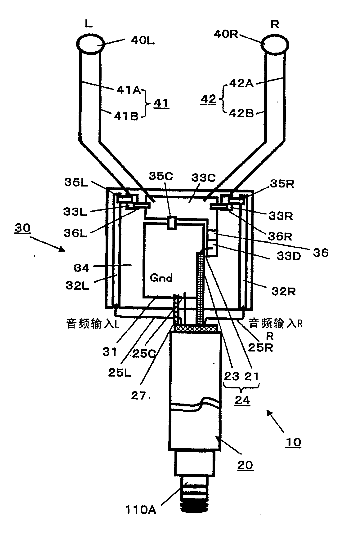
如图5所示,连接块30具有衬底34,在衬底34上形成有:在其中央的接地图案31;用于立体声音频信号的传输线图案32L、32R,设置在接地图案31的两侧;三个连接盘33L、33R、33C,设置在接地图案31的前缘部分;以及连接盘33D,设置在接地图案31的一侧。在该衬底34上设置有:高频扼流圈35L、35R,用于通过其将立体声音频信号的传输线图案32L、32R的端部连接到前述三个连接盘33L、33R、33C中的第一和第二连接盘33L、33R;高频扼流圈35C,用于通过其将接地图案31连接到三个连接盘33L、33R、33C中的第三连接盘33C;片式电容器36L,用于通过其将第一连接盘33L与第三连接盘33C连接;片式电容器36R,用于通过其将第二连接盘33R与第三连接盘33C连接;和片式电容器36,用于通过其将第三连接盘33C和第四连接盘33D连接。As shown in FIG. 5 , the
并且,在该连接块30中,包括两条信号线41A、41B的用于向左侧耳机40L提供左声道音频信号的左侧耳机电缆41连接到第一连接盘31L和第三连接盘33C,另外,包括两条信号线42A、42B的用于向右侧耳机40R提供右声道音频信号的右侧耳机电缆42连接到第二连接盘33R和第三连接盘33C。And, in this
前述屏蔽电缆20也以下述方式连接到该连接块30。The aforementioned shielded
即,屏蔽电缆20的左侧音频信号线25L和右侧音频信号线25R连接到形成在衬底34上的用于音频信号的传输线图案32L和32R,并且其头戴耳机检测信号线25C也连接到接地图案31。另外,在接地图案31上,布置构成屏蔽电缆20的轴向结构的中心导体21和屏蔽线23,屏蔽线23连接到接地图案31,而中心导体21的一端连接到第四连接盘33D。屏蔽线27直接连接到GND 31。That is, the left
以示例方式,用于在第三连接盘33C和第四连接盘33D之间通过其进行连接的片式电容器36可以由在可动端7和调谐器单元121之间插入的用于防止击穿的电容器(未示出)代替。这种情形中,构成屏蔽电缆20中的同轴结构的中心导体21的一端直接连接到第三连接盘33C。By way of example, the
这里,在本发明的该优选示例实施例中,例如使用MurataManufacturing有限公司生产的BLM18HD102SN1,型号1608的铁氧体磁珠作为前述的高频扼流圈35L、35R、35C。使用这种铁氧体磁珠的高频扼流圈35L、35R、35C对低于20kHz的频段中的音频信号变为低阻抗,而对高频信号是高阻抗,从而阻止了高频信号的通过。另外,分别使用电容为10pF的片式电容器作为片式电容器36L、36R、36C,其对低于20kHz的频段中的音频信号变为高阻抗以阻止音频信号通过,而对高频信号变为低阻抗。Here, in this preferred exemplary embodiment of the present invention, for example, ferrite beads of BLM18HD102SN1, model 1608 produced by Murata Manufacturing Co., Ltd. are used as the aforementioned high-frequency choke coils 35L, 35R, 35C. The high-frequency choke coils 35L, 35R, and 35C using such ferrite beads become low impedance to audio signals in the frequency band below 20 kHz and high impedance to high-frequency signals, thereby preventing high-frequency signals from being choked. pass. In addition, as the
如图6所示的示意电路图所指示的,该耳机天线10具有从两侧引出的耳机电缆41、42,其中每条耳机电缆包括两条信号线:作为左侧/右侧信号线和GND的41A、41B/42A、42B,用于将音频信号传输到立体声耳机的扬声器40L、40R,然后为了将音频信号与高频信号分开,如此进行配置:在音频信号的输入部分以及在连接到地的部分,即在连接盘的33L、33R、33C的部分,提供使用铁氧体磁珠的高频波扼流圈35L、35R、35C,这些高频波扼流圈在电视广播中使用的频段中变为高阻抗(1kΩ或更大),而在音频频段(小于20kHz)中变为低阻抗,从而将音频信号和高频信号分开。As indicated by the schematic circuit diagram shown in FIG. 6, the
即,因为在每侧包含两条信号线41A、41B/42A、42B的耳机电缆41、42连接到作为与高频相关联的同轴电缆23信号线的中心导体21,因此,为了将关于音频范围的信号从其中分离,将其配置为经由10pF的片式电容器36L、36R在连接盘33L或33R与33C之间进行连接,以便分离音频波段范围中的信号,并在RF信号(电视波段的频率范围)中连接。That is, since the
这里,在日本被分配给电视广播使用的频段是VHF波段中的90M至108MHz(1~3频道)和170M至222MHz(4~12频道),以及UHF波段的470M至770MHz(13~62频道)。Here, the frequency bands allocated for TV broadcasting in Japan are 90M to 108MHz (channels 1 to 3) and 170M to 222MHz (channels 4 to 12) in the VHF band, and 470M to 770MHz (channels 13 to 62) in the UHF band. .
因此,根据该耳机天线10,通过进行配置使得覆盖同轴电缆24和用于音频信号的信号线25L、25R的屏蔽线27直接连接到GND 31,提供了套筒天线(sleeve antenna)结构,以将耳机电缆41、42和屏蔽线27用作在其线长上谐振的天线,其中它们各自的长度被调节,以便能够接收VHF波段中的100MHz。Therefore, according to this
在根据本发明的该示例实施例的耳机天线10中,同轴电缆24的特性阻抗设置为75Ω,屏蔽电缆20的长度为70cm,耳机电缆41、42的长度为50cm,并且其被调节为在100MHz处谐振。在200MHz处,其被配置为能够作为1λ天线进行接收。在UHF中,其被配置为利用100MHz和200MHz的谐波振荡(三次谐波、五次谐波、七次谐波)。In the
由于其套筒结构,根据本发明实施例的耳机天线10作为天线变得稳定,并且可以向连接块30添加各种功能。Due to its sleeve structure, the
例如,对于在便携式电话中的使用,通过实现图7所示的电路配置,可以向其增加麦克风12的功能,而不会降低天线增益。同样,通过增加如图8所示的放大器14,允许在天线附近放置放大器14,使得作为一个系统,NF(噪声因子)获得显著改善。For example, for use in a cellular phone, by implementing the circuit configuration shown in FIG. 7, the function of the
这里,虽然在上述耳机天线10中,两条耳机电缆41、42的长度被设置为相等,但是,也可以将两条耳机电缆41、42各自从连接块30中的连接盘33L、33R、33C到耳机40L、40R的长度改变,以便能够对应不同频率。Here, although in the above-mentioned
另外,如图9所示的耳机天线10A,通过在两条耳机电缆41、42之一(例如,用于左侧音频信号的耳机电缆41)的途中部分插入高频扼流圈(铁氧体磁珠)35A、35B,其可以被配置以分离高频信号,并缩短其谐振长度。在图9所示的耳机天线10A中,其被设置使得一个耳机天线41中的谐振长度为250mm,而另一个耳机天线42中的谐振长度为400mm,同轴电缆21的特性阻抗为75Ω,并且屏蔽电缆20的长度是600mm。以示例的方式,在该耳机天线10A中,其他组件与前述耳机天线10相同,因此,相同的组件用与图9中相同的符号和数字表示,并省略了对它们的详细描述。In addition, the earphone antenna 10A shown in FIG. Magnetic beads) 35A, 35B, which can be configured to separate high-frequency signals and shorten their resonance length. In the earphone antenna 10A shown in FIG. 9, which is set so that the resonance length in one
另外,本发明也可以应用于使用单根耳机电缆的单声道耳机的情况。In addition, the present invention can also be applied to the case of a monaural earphone using a single earphone cable.
本发明包含涉及于2004年6月4日向日本专利局提交的日本专利申请No.JP2004-167551的主题,其全部内容通过引用结合于此。The present invention contains subject matter related to Japanese Patent Application No. JP2004-167551 filed in the Japan Patent Office on Jun. 4, 2004, the entire content of which is hereby incorporated by reference.
Claims (5)
Applications Claiming Priority (2)
| Application Number | Priority Date | Filing Date | Title |
|---|---|---|---|
| JP167551/2004 | 2004-06-04 | ||
| JP2004167551A JP3933148B2 (en) | 2004-06-04 | 2004-06-04 | Earphone antenna and portable radio equipped with the earphone antenna |
Publications (2)
| Publication Number | Publication Date |
|---|---|
| CN1707854A CN1707854A (en) | 2005-12-14 |
| CN100583553C true CN100583553C (en) | 2010-01-20 |
Family
ID=34980226
Family Applications (1)
| Application Number | Title | Priority Date | Filing Date |
|---|---|---|---|
| CN200510073582A Expired - Fee Related CN100583553C (en) | 2004-06-04 | 2005-06-02 | Headphone Antennas and Portable Radio Equipment Equipped with Headphone Antennas |
Country Status (6)
| Country | Link |
|---|---|
| US (1) | US7373169B2 (en) |
| EP (2) | EP2276115B1 (en) |
| JP (1) | JP3933148B2 (en) |
| KR (1) | KR101105483B1 (en) |
| CN (1) | CN100583553C (en) |
| TW (1) | TWI267229B (en) |
Families Citing this family (38)
| Publication number | Priority date | Publication date | Assignee | Title |
|---|---|---|---|---|
| JP4023500B2 (en) * | 2004-08-03 | 2007-12-19 | ソニー株式会社 | Earphone antenna |
| CN101111971B (en) * | 2005-02-02 | 2012-03-14 | 松下电器产业株式会社 | Connecting Cable Integrated Antenna Unit and Radio Equipment |
| JP4569449B2 (en) * | 2005-11-22 | 2010-10-27 | ソニー株式会社 | Receiving machine |
| RU2465738C2 (en) * | 2006-02-22 | 2012-10-27 | Медиа Тек Инк. | Mobile communication device with internal antennae |
| JP4904895B2 (en) * | 2006-04-12 | 2012-03-28 | ソニー株式会社 | Antenna device |
| GB2442032A (en) * | 2006-09-25 | 2008-03-26 | Antenova Ltd | Earphone cable antenna arrangements and circuitry |
| US8005429B2 (en) * | 2006-09-27 | 2011-08-23 | Hewlett-Packard Development Company, L.P. | Wireless communication noise suppression system |
| US7701398B2 (en) | 2006-10-06 | 2010-04-20 | Sony Ericsson Mobile Communications Ab | Antenna for portable communication device |
| US8094859B2 (en) * | 2006-12-14 | 2012-01-10 | Sharp Kabushiki Kaisha | Dipole antenna device, earphone antenna device, and wireless communication terminal device connected to the device |
| US7912501B2 (en) | 2007-01-05 | 2011-03-22 | Apple Inc. | Audio I/O headset plug and plug detection circuitry |
| JP2008219809A (en) * | 2007-03-07 | 2008-09-18 | Sony Corp | Relay device |
| JP4962106B2 (en) * | 2007-04-11 | 2012-06-27 | ソニー株式会社 | Antenna cable |
| TWI366947B (en) | 2007-07-30 | 2012-06-21 | Htc Corp | Headset antenna and connector thereof |
| CN101359764B (en) * | 2007-07-30 | 2013-08-28 | 宏达国际电子股份有限公司 | Earphone antenna |
| US7982683B2 (en) * | 2007-09-26 | 2011-07-19 | Ibiquity Digital Corporation | Antenna design for FM radio receivers |
| EP2225798A1 (en) * | 2007-12-20 | 2010-09-08 | Nxp B.V. | Headset loop antenna for audio devices |
| US7937109B2 (en) * | 2008-01-24 | 2011-05-03 | Hewlett-Packard Development Company, L.P. | Current source driver for common ground signal interface |
| US8867765B2 (en) * | 2008-02-06 | 2014-10-21 | Starkey Laboratories, Inc. | Antenna used in conjunction with the conductors for an audio transducer |
| US20090325633A1 (en) * | 2008-06-30 | 2009-12-31 | Sony Ericsson Mobile Communications Ab | Method for reducing a disturbance in an output signal caused by a disturbing signal in a multiport connector, multiport connector circuit, and mobile device |
| WO2010052205A1 (en) * | 2008-11-05 | 2010-05-14 | Tomtom International B.V. | Antenna arrangement apparatus |
| TWI487187B (en) | 2009-01-22 | 2015-06-01 | Wistron Neweb Corp | Feeding apparatus for monopole antenna and related analog broadcast play system and integration system |
| JP5387084B2 (en) * | 2009-03-24 | 2014-01-15 | ソニー株式会社 | Receiver |
| TWI514671B (en) * | 2010-10-29 | 2015-12-21 | Fih Hong Kong Ltd | Earphone antenna, earphone devcie and broadcasting receiving device using the same |
| WO2012092236A2 (en) * | 2010-12-30 | 2012-07-05 | Skycross, Inc. | Headphone antenna for radio communications device |
| CN102290693B (en) * | 2011-04-25 | 2015-07-22 | 中兴通讯股份有限公司 | Connecting device, earphone antenna and earphone |
| CN102427192A (en) * | 2011-08-05 | 2012-04-25 | 中兴通讯股份有限公司 | Connector, earphone antenna and earphone |
| KR101867846B1 (en) * | 2011-11-01 | 2018-06-19 | 삼성전자주식회사 | Television tuner module and Broadcast receiving apparatus having the same |
| US9509044B2 (en) | 2012-02-29 | 2016-11-29 | Htc Corporation | Headset, circuit structure of mobile apparatus, and mobile apparatus |
| JP2013219746A (en) | 2012-03-15 | 2013-10-24 | Seiko Epson Corp | Sleeve antenna and wireless communication device |
| CN102610914B (en) * | 2012-03-30 | 2015-03-11 | 上海华勤通讯技术有限公司 | China Mobile Multimedia Broadcasting (CMMB) antenna |
| US10045118B2 (en) | 2012-07-02 | 2018-08-07 | Fox Digital Enterprises, Inc. | Integrated antenna for receiving television broadcasts |
| US8903102B2 (en) * | 2012-07-02 | 2014-12-02 | Fox Digital Enterprises, Inc. | Integrated earbud antenna for receiving television broadcasts |
| EP2874232B1 (en) * | 2012-07-13 | 2020-11-04 | Sony Corporation | Antenna |
| CN104427438A (en) * | 2013-08-22 | 2015-03-18 | 深圳富泰宏精密工业有限公司 | Audio play system, earphone used by the same, and automatic control method |
| CN104507008B (en) * | 2014-12-26 | 2018-10-12 | 佳禾智能科技股份有限公司 | A kind of method and apparatus of audio signal switching input |
| JP6650641B2 (en) * | 2016-03-03 | 2020-02-19 | 株式会社フェニックスソリューション | Director |
| TWI628855B (en) * | 2016-06-15 | 2018-07-01 | 群邁通訊股份有限公司 | Electronic device with FM function and FM antenna switching method thereof |
| CN106254587A (en) * | 2016-08-29 | 2016-12-21 | 珠海格力电器股份有限公司 | Antenna control system, control method and mobile communication terminal |
Family Cites Families (30)
| Publication number | Priority date | Publication date | Assignee | Title |
|---|---|---|---|---|
| JPS482637U (en) | 1971-05-28 | 1973-01-12 | ||
| US3720874A (en) * | 1971-11-08 | 1973-03-13 | Motorola Inc | Dipole antenna arrangement for radio with separate speaker-microphone assembly |
| JPS5328859B2 (en) | 1972-10-05 | 1978-08-17 | ||
| JPS5277636A (en) | 1975-12-24 | 1977-06-30 | Kokusai Denshin Denwa Co Ltd | Main wire transfer system by group specification |
| JPS5714505U (en) * | 1980-06-26 | 1982-01-25 | ||
| DE3244461A1 (en) | 1982-12-01 | 1984-06-07 | Siemens AG, 1000 Berlin und 8000 München | INTEGRATED SEMICONDUCTOR CIRCUIT WITH A CONTACT LAYER LEVEL consisting of an ALUMINUM / SILICON ALLOY |
| JPS59132475A (en) | 1983-01-18 | 1984-07-30 | Matsushita Electric Ind Co Ltd | tape recorder |
| JPS6135412A (en) | 1984-07-28 | 1986-02-19 | Olympus Optical Co Ltd | Optical information detecting device of image formation optical system |
| JPH073087B2 (en) | 1986-09-12 | 1995-01-18 | 大建工業株式会社 | Humidity control composite |
| US5361405A (en) * | 1989-09-14 | 1994-11-01 | Ramsey Electronics, Inc. | Aircraft band radio receiver which does not radiate interfering signals |
| JPH03109414A (en) | 1989-09-21 | 1991-05-09 | Sanyo Chem Ind Ltd | Production of flame retardant polyurethane foam |
| SE466427B (en) * | 1990-06-25 | 1992-02-10 | Ericsson Telefon Ab L M | HAND RELEASE MODULE FOR A MOBILE PHONE |
| JP2714229B2 (en) | 1990-06-26 | 1998-02-16 | 三洋電機株式会社 | Wrist watch type portable wireless telephone |
| JPH0688015A (en) | 1991-12-31 | 1994-03-29 | Union Carbide Chem & Plast Technol Corp | Polyurethane low-profile additive for polyester-based molding composition |
| JPH0865026A (en) | 1994-08-25 | 1996-03-08 | Ricoh Co Ltd | Rotating retractable antenna feed line |
| US5574769A (en) * | 1995-11-09 | 1996-11-12 | Progressive Electronics, Inc. | Inductive amplifier having automatic gain control for butt set |
| JPH09199237A (en) | 1996-01-22 | 1997-07-31 | Nippon Carbide Ind Co Inc | Shielded cable with connector |
| JPH09331209A (en) | 1996-04-09 | 1997-12-22 | Sony Corp | Audio device and headphone having FM receiving circuit |
| US6845253B1 (en) * | 2000-09-27 | 2005-01-18 | Time Domain Corporation | Electromagnetic antenna apparatus |
| DE60237015D1 (en) * | 2001-05-25 | 2010-08-26 | Panasonic Elec Works Co Ltd | CONNECTOR |
| CA2460658A1 (en) * | 2001-09-17 | 2003-03-27 | Roke Manor Research Limited | A headphone |
| GB0127566D0 (en) | 2001-11-19 | 2002-01-09 | Psion Digital Ltd | Antenna for a portable radio device |
| JP2003163529A (en) | 2001-11-28 | 2003-06-06 | Alps Electric Co Ltd | Headphone serving as diversity antenna |
| GB2393858B (en) | 2002-10-03 | 2004-12-22 | Brand Rex Ltd | Improvements in and relating to electrical connectors |
| US7512448B2 (en) * | 2003-01-10 | 2009-03-31 | Phonak Ag | Electrode placement for wireless intrabody communication between components of a hearing system |
| JP4363865B2 (en) * | 2003-02-28 | 2009-11-11 | ソニー株式会社 | Earphone antenna and radio |
| JP3880571B2 (en) | 2003-10-29 | 2007-02-14 | Necアクセステクニカ株式会社 | Antenna device |
| JP4026648B2 (en) * | 2004-04-19 | 2007-12-26 | ソニー株式会社 | Earphone antenna and portable radio equipped with the earphone antenna |
| TWI277355B (en) * | 2004-07-08 | 2007-03-21 | Sony Corp | Earphone antenna connecting device and portable wireless device |
| JP4023500B2 (en) * | 2004-08-03 | 2007-12-19 | ソニー株式会社 | Earphone antenna |
-
2004
- 2004-06-04 JP JP2004167551A patent/JP3933148B2/en not_active Expired - Fee Related
-
2005
- 2005-05-18 TW TW094116102A patent/TWI267229B/en not_active IP Right Cessation
- 2005-05-30 KR KR1020050045436A patent/KR101105483B1/en not_active Expired - Fee Related
- 2005-06-02 CN CN200510073582A patent/CN100583553C/en not_active Expired - Fee Related
- 2005-06-03 US US11/144,572 patent/US7373169B2/en not_active Expired - Fee Related
- 2005-06-03 EP EP10008199.1A patent/EP2276115B1/en not_active Expired - Lifetime
- 2005-06-03 EP EP05012038A patent/EP1605545B1/en not_active Expired - Lifetime
Also Published As
| Publication number | Publication date |
|---|---|
| US7373169B2 (en) | 2008-05-13 |
| JP2005348252A (en) | 2005-12-15 |
| KR20060046258A (en) | 2006-05-17 |
| JP3933148B2 (en) | 2007-06-20 |
| EP2276115A1 (en) | 2011-01-19 |
| CN1707854A (en) | 2005-12-14 |
| EP2276115B1 (en) | 2016-01-06 |
| TW200614592A (en) | 2006-05-01 |
| EP1605545A1 (en) | 2005-12-14 |
| TWI267229B (en) | 2006-11-21 |
| KR101105483B1 (en) | 2012-01-13 |
| EP1605545B1 (en) | 2013-03-27 |
| US20060014560A1 (en) | 2006-01-19 |
Similar Documents
| Publication | Publication Date | Title |
|---|---|---|
| CN100583553C (en) | Headphone Antennas and Portable Radio Equipment Equipped with Headphone Antennas | |
| EP1589609B1 (en) | Earphone antenna and portable radio equipment provided with earphone antenna | |
| US7840242B2 (en) | Earphone antenna | |
| US7064720B2 (en) | Earphone antenna | |
| JP4904895B2 (en) | Antenna device | |
| US20070032130A1 (en) | Earphone antenna connecting device and portable wireless device | |
| JP3938118B2 (en) | Earphone antenna and portable radio equipped with the earphone antenna | |
| CN103262428A (en) | Whip antenna for mobile communication devices | |
| CN100452531C (en) | Headphone Antennas and Portable Radio Equipment Equipped with Headphone Antennas | |
| JP5151706B2 (en) | Antenna device and plug device | |
| CN106688142B (en) | Antenna with a shield | |
| KR100498676B1 (en) | A earphone antenna for receiving high frequency broadcasting signal | |
| JP2008258728A (en) | Earphone antenna device |
Legal Events
| Date | Code | Title | Description |
|---|---|---|---|
| C06 | Publication | ||
| PB01 | Publication | ||
| C10 | Entry into substantive examination | ||
| SE01 | Entry into force of request for substantive examination | ||
| C14 | Grant of patent or utility model | ||
| GR01 | Patent grant | ||
| CF01 | Termination of patent right due to non-payment of annual fee | ||
| CF01 | Termination of patent right due to non-payment of annual fee |
Granted publication date: 20100120 Termination date: 20190602 |