CN100551301C - Load bearing surface - Google Patents
Load bearing surface Download PDFInfo
- Publication number
- CN100551301C CN100551301C CNB2005100770110A CN200510077011A CN100551301C CN 100551301 C CN100551301 C CN 100551301C CN B2005100770110 A CNB2005100770110 A CN B2005100770110A CN 200510077011 A CN200510077011 A CN 200510077011A CN 100551301 C CN100551301 C CN 100551301C
- Authority
- CN
- China
- Prior art keywords
- diaphragm
- load bearing
- along
- molded
- membrane
- Prior art date
- Legal status (The legal status is an assumption and is not a legal conclusion. Google has not performed a legal analysis and makes no representation as to the accuracy of the status listed.)
- Expired - Lifetime
Links
Images


Classifications
-
- A—HUMAN NECESSITIES
- A47—FURNITURE; DOMESTIC ARTICLES OR APPLIANCES; COFFEE MILLS; SPICE MILLS; SUCTION CLEANERS IN GENERAL
- A47C—CHAIRS; SOFAS; BEDS
- A47C5/00—Chairs of special materials
- A47C5/12—Chairs of special materials of plastics, with or without reinforcement
-
- A—HUMAN NECESSITIES
- A47—FURNITURE; DOMESTIC ARTICLES OR APPLIANCES; COFFEE MILLS; SPICE MILLS; SUCTION CLEANERS IN GENERAL
- A47C—CHAIRS; SOFAS; BEDS
- A47C7/00—Parts, details, or accessories of chairs or stools
- A47C7/02—Seat parts
- A47C7/14—Seat parts of adjustable shape; elastically mounted ; adaptable to a user contour or ergonomic seating positions
- A47C7/144—Seat parts of adjustable shape; elastically mounted ; adaptable to a user contour or ergonomic seating positions with array of movable supports
-
- A—HUMAN NECESSITIES
- A47—FURNITURE; DOMESTIC ARTICLES OR APPLIANCES; COFFEE MILLS; SPICE MILLS; SUCTION CLEANERS IN GENERAL
- A47C—CHAIRS; SOFAS; BEDS
- A47C7/00—Parts, details, or accessories of chairs or stools
- A47C7/02—Seat parts
- A47C7/28—Seat parts with tensioned springs, e.g. of flat type
- A47C7/282—Seat parts with tensioned springs, e.g. of flat type with mesh-like supports, e.g. elastomeric membranes
-
- A—HUMAN NECESSITIES
- A47—FURNITURE; DOMESTIC ARTICLES OR APPLIANCES; COFFEE MILLS; SPICE MILLS; SUCTION CLEANERS IN GENERAL
- A47C—CHAIRS; SOFAS; BEDS
- A47C7/00—Parts, details, or accessories of chairs or stools
- A47C7/02—Seat parts
- A47C7/28—Seat parts with tensioned springs, e.g. of flat type
- A47C7/287—Seat parts with tensioned springs, e.g. of flat type with combinations of different types flat type tensioned springs
-
- A—HUMAN NECESSITIES
- A47—FURNITURE; DOMESTIC ARTICLES OR APPLIANCES; COFFEE MILLS; SPICE MILLS; SUCTION CLEANERS IN GENERAL
- A47C—CHAIRS; SOFAS; BEDS
- A47C7/00—Parts, details, or accessories of chairs or stools
- A47C7/62—Accessories for chairs
- A47C7/72—Adaptations for incorporating lamps, radio sets, bars, telephones, ventilation, heating or cooling arrangements or the like
- A47C7/74—Adaptations for incorporating lamps, radio sets, bars, telephones, ventilation, heating or cooling arrangements or the like for ventilation, heating or cooling
- A47C7/742—Adaptations for incorporating lamps, radio sets, bars, telephones, ventilation, heating or cooling arrangements or the like for ventilation, heating or cooling for ventilating or cooling
- A47C7/746—Adaptations for incorporating lamps, radio sets, bars, telephones, ventilation, heating or cooling arrangements or the like for ventilation, heating or cooling for ventilating or cooling without active means, e.g. with openings or heat conductors
-
- B—PERFORMING OPERATIONS; TRANSPORTING
- B29—WORKING OF PLASTICS; WORKING OF SUBSTANCES IN A PLASTIC STATE IN GENERAL
- B29C—SHAPING OR JOINING OF PLASTICS; SHAPING OF MATERIAL IN A PLASTIC STATE, NOT OTHERWISE PROVIDED FOR; AFTER-TREATMENT OF THE SHAPED PRODUCTS, e.g. REPAIRING
- B29C55/00—Shaping by stretching, e.g. drawing through a die; Apparatus therefor
- B29C55/02—Shaping by stretching, e.g. drawing through a die; Apparatus therefor of plates or sheets
- B29C55/10—Shaping by stretching, e.g. drawing through a die; Apparatus therefor of plates or sheets multiaxial
- B29C55/12—Shaping by stretching, e.g. drawing through a die; Apparatus therefor of plates or sheets multiaxial biaxial
-
- B—PERFORMING OPERATIONS; TRANSPORTING
- B29—WORKING OF PLASTICS; WORKING OF SUBSTANCES IN A PLASTIC STATE IN GENERAL
- B29D—PRODUCING PARTICULAR ARTICLES FROM PLASTICS OR FROM SUBSTANCES IN A PLASTIC STATE
- B29D7/00—Producing flat articles, e.g. films or sheets
- B29D7/01—Films or sheets
-
- F—MECHANICAL ENGINEERING; LIGHTING; HEATING; WEAPONS; BLASTING
- F16—ENGINEERING ELEMENTS AND UNITS; GENERAL MEASURES FOR PRODUCING AND MAINTAINING EFFECTIVE FUNCTIONING OF MACHINES OR INSTALLATIONS; THERMAL INSULATION IN GENERAL
- F16F—SPRINGS; SHOCK-ABSORBERS; MEANS FOR DAMPING VIBRATION
- F16F1/00—Springs
- F16F1/36—Springs made of rubber or other material having high internal friction, e.g. thermoplastic elastomers
-
- F—MECHANICAL ENGINEERING; LIGHTING; HEATING; WEAPONS; BLASTING
- F16—ENGINEERING ELEMENTS AND UNITS; GENERAL MEASURES FOR PRODUCING AND MAINTAINING EFFECTIVE FUNCTIONING OF MACHINES OR INSTALLATIONS; THERMAL INSULATION IN GENERAL
- F16F—SPRINGS; SHOCK-ABSORBERS; MEANS FOR DAMPING VIBRATION
- F16F2226/00—Manufacturing; Treatments
-
- Y—GENERAL TAGGING OF NEW TECHNOLOGICAL DEVELOPMENTS; GENERAL TAGGING OF CROSS-SECTIONAL TECHNOLOGIES SPANNING OVER SEVERAL SECTIONS OF THE IPC; TECHNICAL SUBJECTS COVERED BY FORMER USPC CROSS-REFERENCE ART COLLECTIONS [XRACs] AND DIGESTS
- Y10—TECHNICAL SUBJECTS COVERED BY FORMER USPC
- Y10T—TECHNICAL SUBJECTS COVERED BY FORMER US CLASSIFICATION
- Y10T428/00—Stock material or miscellaneous articles
- Y10T428/24—Structurally defined web or sheet [e.g., overall dimension, etc.]
- Y10T428/24628—Nonplanar uniform thickness material
- Y10T428/24669—Aligned or parallel nonplanarities
- Y10T428/24694—Parallel corrugations
- Y10T428/24711—Plural corrugated components
- Y10T428/24719—Plural corrugated components with corrugations of respective components intersecting in plane projection
-
- Y—GENERAL TAGGING OF NEW TECHNOLOGICAL DEVELOPMENTS; GENERAL TAGGING OF CROSS-SECTIONAL TECHNOLOGIES SPANNING OVER SEVERAL SECTIONS OF THE IPC; TECHNICAL SUBJECTS COVERED BY FORMER USPC CROSS-REFERENCE ART COLLECTIONS [XRACs] AND DIGESTS
- Y10—TECHNICAL SUBJECTS COVERED BY FORMER USPC
- Y10T—TECHNICAL SUBJECTS COVERED BY FORMER US CLASSIFICATION
- Y10T428/00—Stock material or miscellaneous articles
- Y10T428/24—Structurally defined web or sheet [e.g., overall dimension, etc.]
- Y10T428/24942—Structurally defined web or sheet [e.g., overall dimension, etc.] including components having same physical characteristic in differing degree
- Y10T428/2495—Thickness [relative or absolute]
- Y10T428/24967—Absolute thicknesses specified
- Y10T428/24975—No layer or component greater than 5 mils thick
Landscapes
- Engineering & Computer Science (AREA)
- Mechanical Engineering (AREA)
- General Engineering & Computer Science (AREA)
- Springs (AREA)
- Diaphragms And Bellows (AREA)
- Mattresses And Other Support Structures For Chairs And Beds (AREA)
- Vibration Prevention Devices (AREA)
- Manufacture Of Macromolecular Shaped Articles (AREA)
Abstract
一种沿不同方向有不同负荷支承特性的弹性负荷支承表面。在一个实施例中,该表面包括,例如,靠压缩成拉伸而仅在一个方向定向的弹性膜片。在另一个实施例中,该表面包括可沿不同方向改变负荷支承特性的机械结构,例如连接件,厚度的变化和孔。另一方面,本发明提供多层负荷支承表面,在这种表面中多层共同提供在所述表面区域内可变的可控力/挠曲分布。在一个实施例中,上层包括许多松弛连接的节点和下层有许多独立支承每个节点的弹性元件。

A resilient load bearing surface having different load bearing characteristics in different directions. In one embodiment, the surface comprises, for example, an elastic diaphragm oriented in only one direction by compression into tension. In another embodiment, the surface comprises mechanical structures that vary the load bearing characteristics in different directions, such as connectors, thickness variations, and holes. In another aspect, the invention provides a multi-layer load bearing surface in which the multiple layers together provide a variable, controllable force/deflection distribution within the surface area. In one embodiment, the upper layer comprises a plurality of loosely connected nodes and the lower layer comprises a plurality of elastic elements that independently support each node.
Description
技术领域 technical field
本发明涉及负荷支承表面,更具体说,涉及弹性负荷支承表面,例如椅子或长凳的座位或靠背,或床,帆布床或其它类似产品的支承表面。This invention relates to load bearing surfaces and more particularly to resilient load bearing surfaces such as the seat or back of a chair or bench, or the bearing surface of a bed, cot or other similar product.
背景技术 Background technique
人们不断地努力发展新的改进负荷支承表面。在一般负荷支承表面方面,这种努力的主要目的是获得耐用和价廉的负荷支承表面。在座位和其他人体支承表面应用方面,致力于舒适性也是重要的。例如,对座位而言,提供一种舒适的,并在长时间使用时不会引起身体疲劳的表面也会很重要。我们知道,具体应用所需的负荷特性(例如,硬度,回弹性,力度/模挠曲断面)是随不同应用而变的,因此,也期望能得到可在设计和制造时方便地为不同应用而调整支承表面。Efforts are continually being made to develop new and improved load bearing surfaces. With regard to load bearing surfaces in general, the main purpose of this effort is to obtain a durable and inexpensive load bearing surface. A focus on comfort is also important in seating and other body support surface applications. For example, for seating, it is also important to provide a surface that is comfortable and does not cause physical fatigue during prolonged use. We know that the load characteristics (e.g., hardness, resilience, force/mode deflection section) required for a specific application will vary from application to application, so it is also desirable to have while adjusting the bearing surface.
目前已能为大量不同应用提供模制负荷支承表面。例如,可在很多知名供应商处购买到的模制塑料椅(例如,草地椅)。虽然这些模制塑料椅提供了廉价的座椅选择,但它们不能提供较贵的负荷支承表面,诸如舒适的软垫所具备的支承和舒适程度。更确切的说,它们提供的是基本上线性的力度、挠曲断面,它给予典型模制座位表面的是鼓形物或蹦床的感觉。在座位和其他人体支承应用中,其结果可能是不舒服的,和有时是人类工程方面无法接受的负荷支承表面。此外,传统模制座位特性的调节能力是相对局限的。可以采用不同的材料和材料厚度来保障对座位特性的有限控制程度,但这种控制程度在很多应用中是不够的。Molded load bearing surfaces are now available for a number of different applications. For example, molded plastic chairs (eg, lawn chairs) are available from many well-known suppliers. While these molded plastic chairs provide an inexpensive seating option, they do not provide the level of support and comfort that more expensive load bearing surfaces, such as comfortable upholstery, provide. Rather, they provide a substantially linear dynamic, deflection profile that gives the typical molded seating surface the feel of a drum or trampoline. In seating and other body support applications, the result can be uncomfortable and sometimes ergonomically unacceptable load bearing surfaces. Furthermore, the ability to adjust the characteristics of conventional molded seats is relatively limited. Different materials and material thicknesses can be used to allow a limited degree of control over the seat characteristics, but this degree of control is not sufficient in many applications.
在座位工业中也更多地采用弹性纤维。弹性纤维可提供舒适,透气的座位结构。弹性纤维通常用高科技弹性材料单丝和多丝纱线的复合编织方法制造。这种工艺导致相对昂贵的表面。虽然弹性纤维表面在很多应用中可能相当舒适,但在施加负荷时,它们通常会像吊索一样弯曲下垂。一些人类工程专家将这种弯曲下垂称为“吊床效应”并因它可造成臂部向上转动而认为它是不理想的。为减轻吊床效应,很多悬挂型座位都拉得非常紧,以减少负荷作用下的下垂量。这降低了座椅的软垫般感觉,它的感觉更像拉紧的鼓面。其结果是,弹性纤维在所有应用中都可能并不理想。Elastic fibers are also being used more in the seating industry. Elastane provides a comfortable, breathable seat structure. Elastane fibers are usually manufactured using composite weaving methods of monofilament and multifilament yarns of high-tech elastic materials. This process results in a relatively expensive surface. While spandex surfaces can be quite comfortable for many applications, they often bend and sag like a sling when a load is applied. Some ergonomic experts refer to this sag as the "hammock effect" and consider it undesirable because it can cause the arm to rotate upward. To mitigate the hammock effect, many suspension seats are stretched very tightly to reduce the amount of sag under load. This reduces the cushion-like feel of the seat, which feels more like a taut drumhead. As a result, spandex may not be ideal for all applications.
因此,仍然需要一种弹性负荷支承表面,它可提供应对不同负荷的非线性力度/弯曲下垂断面。Accordingly, there remains a need for an elastic load bearing surface that provides a non-linear force/bending sag profile for varying loads.
发明内容 Contents of the invention
一方面,本发明提供一种在不同方向具有不同支承特性的弹性负荷支承表面。在一个实施例中,彼此垂直方向上的支承特性是不同的(或无相互影响,或去耦的)。In one aspect, the invention provides a resiliently loaded bearing surface having different bearing properties in different directions. In one embodiment, the support properties in directions perpendicular to each other are different (or non-interacting, or decoupled).
在这方面的一个实施例中,负荷支承表面包括模制弹性膜片,它通过对分子层上的膜片结构的取向影响而获得去耦。在这个实施例中,可借助于在某一方向上将膜片压缩或拉伸至为提高弹性物晶体结构对齐所需的程度而使模制弹性膜片定向。该定向工艺改变了膜片的支承特性,造成膜片中沿定向方向的足够弹性和低蠕变度。定向工艺在膜片定向方向的垂直方向上留下很小的弹性。In one embodiment of this aspect, the load bearing surface comprises a molded elastic membrane, which achieves decoupling through orientation influence on the membrane structure on the molecular layer. In this embodiment, the molded elastic membrane can be oriented by compressing or stretching the membrane in a certain direction to the extent required to enhance the alignment of the elastomer crystalline structure. This orientation process changes the support properties of the membrane, resulting in sufficient elasticity and low creep in the membrane along the direction of orientation. The orientation process leaves little elasticity perpendicular to the orientation direction of the membrane.
在另一个实施例中,模制膜片包括能影响膜片支承和负荷支承特性的机械结构。在这个实施例中,膜片可包括在某一方向上无制约地提供“垂度”的狭缝,通道,波纹和其整体元素。如需要,膜片也可被定向并包括机械的去耦结构。In another embodiment, the molded diaphragm includes mechanical structures that affect the diaphragm support and load bearing characteristics. In this embodiment, the membrane may include slits, channels, corrugations and integral elements thereof which provide unrestricted "sag" in one direction. The diaphragm can also be oriented and include mechanical decoupling if desired.
在又一个实施例中,膜片被分隔成许多节点,它们提供了膜片某个位置与另一位置间的独立度。在一个实施例中,膜片界定了许多相互连接的几何形状。例如,膜片可包括由整体连接段相互连接的许多方形或三角形节点。可以改变这些连接段的特性以控制膜片的支承特性。例如,膜片可包括可在负荷下变形或弯曲的许多非平面连接段,以为膜片提供“垂度”。In yet another embodiment, the diaphragm is divided into nodes that provide a degree of independence between one position of the diaphragm and another. In one embodiment, the diaphragm defines a number of interconnected geometries. For example, a membrane may comprise a number of square or triangular nodes interconnected by integral connecting segments. The properties of these connecting segments can be varied to control the support properties of the diaphragm. For example, the membrane may include a number of non-planar connecting segments that may deform or bend under load to provide "sag" to the membrane.
第二方面,本发明提供一种多层负荷支承表面。在本发明这个方面的一个实施例中,负荷支承表面包括相互作用的上和下层。上层可包括许多松散连接的节点。在一个实施例中,上层是有许多用整体连接段相互连接的节点的模制片材。上层可包括从每个节点向下层伸出的整体突出物。这些突出物可与下层中的相应结构相互贴合。多层负荷支承表面可包括布置在上,下层之间的弹簧件。弹簧件可与上层可下层形成整体。例如,下层可包括可接受上层突出物的许多整体模制柔性臂。在一个实施例中,下层可以是去耦的模制弹性膜片。In a second aspect, the invention provides a multilayer load bearing surface. In one embodiment of this aspect of the invention, the load bearing surface comprises interacting upper and lower layers. The upper layer may consist of many loosely connected nodes. In one embodiment, the upper layer is a molded sheet having a plurality of nodes interconnected by integral connecting segments. The upper layer may include integral protrusions projecting from each node to the lower layer. These protrusions can interfit with corresponding structures in the underlying layer. The multi-layer load bearing surface may include spring members disposed between upper and lower layers. The spring member may be integral with the upper or lower layer. For example, the lower layer may include a plurality of integrally molded flexible arms that receive protrusions from the upper layer. In one embodiment, the lower layer may be a decoupled molded elastic diaphragm.
本发明还提供用弹性材料制造负荷支承表面的方法。该方法一般包括如下步骤:(a)模制弹性膜片和(b)通过沿某方向拉伸弹性膜片或用可造成它在该方向流动的方法压缩弹性膜片,而使弹性膜片定向。弹性膜片被拉伸或压缩的程度应使弹性材料沿该定向方向的晶状结构增高对齐度。在一个实施例中,该方法还包括模塑带有一种可在不同于膜片定向的另一方向上使膜片获得机械去耦的结构的弹性膜片。该去耦方向可以垂直于定向方向。The present invention also provides a method of making a load bearing surface from an elastic material. The method generally includes the steps of (a) molding the elastic membrane and (b) orienting the elastic membrane by stretching the elastic membrane in a direction or compressing the elastic membrane in a manner that causes it to flow in that direction . The elastic membrane is stretched or compressed to such an extent that the crystalline structure of the elastic material along the orientation direction is increased in alignment. In one embodiment, the method further includes molding the elastic membrane with a structure that provides mechanical decoupling of the membrane in another direction than the orientation of the membrane. The decoupling direction can be perpendicular to the orientation direction.
在一个实施例中,膜片经如下步骤压缩:(a)产生具有由连接段互相连接的许多节点上表面,(b)产生能在节点处与上层接合的下层和(c)用布置在接合位置处的弹簧件组合上层和下层。在一个实施例中,上层包括从每个节点伸出的整体心棒和下层包括可接受心棒的整体弹簧臂。In one embodiment, the membrane is compressed by (a) creating an upper surface having a number of nodes interconnected by connecting segments, (b) creating a lower layer capable of joining the upper layer at the nodes and (c) creating an upper surface with joints arranged at the joints. The spring element at the location combines the upper and lower tiers. In one embodiment, the upper layer includes an integral mandrel extending from each node and the lower layer includes an integral spring arm that receives the mandrel.
本发明提供一种坚固却又柔性的负荷支承表面。这种弹性负荷支承表面制造起来较为便宜,并提供可通气以阻止热积存的轻型表面。去耦弹性材料所呈现的支承特性特别适用于座位应用,因为它能在不同方向提供不同的弹性和支承度。例如,去耦弹性材料可提供在左右方向有弹性而在前后方向无弹性的座位结构。此外,通过提高弹性材料晶状结构的对准度,膜片中的蠕变水平可显著降低。在该双层实施例中,第二层提供了对负荷支承表面的上/下(或E轴)移动的附加控制,这允许对座位支承和舒适特性实现更多控制。The present invention provides a strong yet flexible load bearing surface. Such resilient load bearing surfaces are less expensive to manufacture and provide a lightweight surface that can be vented to prevent heat build-up. The support characteristics exhibited by decoupling elastomeric materials are particularly suitable for seating applications because they provide varying degrees of elasticity and support in different directions. For example, a decoupling elastic material may provide a seat structure that is elastic in the side-to-side direction but not in the front-to-back direction. Furthermore, by improving the alignment of the elastic material's crystalline structure, the level of creep in the diaphragm can be significantly reduced. In this two-layer embodiment, the second layer provides additional control over the up/down (or E-axis) movement of the load bearing surface, which allows for more control over seat support and comfort characteristics.
在参考下面对优选实施例的详细说明和附图后,会更容易理解本发明的以上和其他目的,优越性和特点。The above and other objects, advantages and features of the present invention will be more easily understood after referring to the following detailed description of preferred embodiments and accompanying drawings.
附图说明 Description of drawings
图1是依照本发明一个实施例的负荷支承表面的透视图。Figure 1 is a perspective view of a load bearing surface in accordance with one embodiment of the present invention.
图2A是有许多节点的另一种负荷支承表面的透视图。Figure 2A is a perspective view of another load bearing surface having a plurality of nodes.
图2B是图2A负荷支承表面一部分的放大透视图。Figure 2B is an enlarged perspective view of a portion of the load bearing surface of Figure 2A.
图3A是定向前的模制弹性膜片顶视图。Figure 3A is a top view of the molded elastic membrane prior to orientation.
图3B是定向期间的模制弹性膜片顶视图。Figure 3B is a top view of the molded elastic membrane during orientation.
图3C是定向后的模制弹性膜片顶视图。Figure 3C is a top view of the molded elastic membrane after orientation.
图4是沿图3C中4-4线截取的模制弹性膜片剖面图。Figure 4 is a cross-sectional view of the molded elastic membrane taken along line 4-4 of Figure 3C.
图5A是第一种可替代负荷支承表面的透视图。Figure 5A is a perspective view of a first alternative load bearing surface.
图5B是沿5B-5B线截取的第一种可替代负荷支承表面的截面图。Figure 5B is a cross-sectional view of a first alternative load bearing surface taken along
图6A是第二种可替代负荷支承表面的透视图。Figure 6A is a perspective view of a second alternative load bearing surface.
图6B是沿6B-6B线截取的第二种可替代负荷支承表面的截面图。Figure 6B is a cross-sectional view of a second alternative load bearing surface taken along
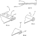
图7A是第三种可替代负荷支承表面的透视图。Figure 7A is a perspective view of a third alternative load bearing surface.
图7B是沿7B-7B线截取的第三种可替代负荷支承表面的截面图。Figure 7B is a cross-sectional view of a third alternative load bearing surface taken along
图8A是具有整体边缘的弹性膜片一部分的放大剖面图。Figure 8A is an enlarged cross-sectional view of a portion of an elastic diaphragm with an integral edge.
图8B是具有第一种可替换整体边缘的弹性膜片一部分的放大剖面图。Figure 8B is an enlarged cross-sectional view of a portion of a flexible membrane having a first alternative integral edge.
图8C是具有第二种可替换整体边缘的弹性膜片一部分的放大剖面图。Figure 8C is an enlarged cross-sectional view of a portion of an elastic membrane having a second alternative integral edge.
图9是依照本发明一个实施例的双层负荷支承表面的透视图。Figure 9 is a perspective view of a dual layer load bearing surface in accordance with one embodiment of the present invention.
图10是图9负荷支承表面一部分的放大透视图。FIG. 10 is an enlarged perspective view of a portion of the load bearing surface of FIG. 9. FIG.
图11是给出一个弹簧和一个节点以及下层一部分的负荷支承表面的分解图。Figure 11 is an exploded view showing a spring and a node and a portion of the lower layer's load bearing surface.
图12是另一种下层的顶视图。Figure 12 is a top view of another lower layer.
图13是第二种可替代下层的顶视图。Figure 13 is a top view of a second alternative lower layer.
图14是带一体化弹簧件的另一种下层的透视图。Figure 14 is a perspective view of an alternative lower layer with integral spring members.
图15是带一体化弹簧件的第二种可替换下层的透视图。Figure 15 is a perspective view of a second alternative lower layer with integral spring members.
图16是带三角形节点的可替换顶层的透视图。Figure 16 is a perspective view of an alternative top layer with triangular nodes.
图17是图16的可替换顶层一个节点的透视图。FIG. 17 is a perspective view of a node of the alternative top layer of FIG. 16. FIG.
具体实施方式 Detailed ways
图1给出依照本发明一个实施例的负荷支承表面10。图1中所示负荷支承表面10是一种模制膜片,它可挂在支承结构,例如椅座架(未示出)上。负荷支承表面10包括沿不同方向的不同支承特性。例如,负荷支承表面可提供X方向上的显著弹性支承力而同时在Y方向上只有较弱的支承力。负荷支承表面支承特性的这种“去耦性”提供了很高的舒适度。为便于公开内容,本发明将结合主要打算用在座位应用中的各种可替代实施例予以说明。但是,本发明并不局限于座位应用,它也可应用于其他负荷支承用途中。所述模制膜片的支承特性是高度可调节的,因而使所述负荷支承表面10可满足大量不同用途中对支承功能的要求。Figure 1 shows a
在图1实施例中,负荷支承表面10包括模制弹性膜片12。在图示实施例中,膜片12是用热塑性聚醚酯弹性胶块共聚体模制而成的。可从Dupont购买到的

图1的膜片12还包括可直接安装到所需支承结构(未示出),例如椅子的座位框架上的一体化边缘16。在所示实施例中,边缘16沿膜片12的周边延伸,其厚度明显大于膜片12的其他部分。边缘16可包括一体化的按扣或其他连接用零件(未示出),以方便膜片12连接到支承结构上。或者,边缘16也可以用紧固件(未示出),例如螺钉或螺栓来连接。边缘16不一定需要沿膜片12完全延伸。它也可以只包括沿其周边不同位置处的一或多段。例如,可以在矩形膜片的每个角上布置一段边缘(未示出)。边缘16也不一定要位于膜片12的周边。在某些应用中,可能希望在膜片12的内部有一或多段边缘。例如,在窄长表面中,可以在膜片中央部分处安排一段边缘以提供中央固定位置(未示出)。图8A-C中给出三种可供选择的边缘结构。图8A中给出的边缘16′有孔17′,以方便边缘16′与支承结构(未示出)的连接。例如,紧固件(未示出)可穿过孔17′。或者,孔17′可贴合在支承结构(未示出),例如支柱,上的连接结构上。图8B给出其截面大体上是圆形的边缘16″。图8C给出的边缘16″′的截面大体为方形。The
如上所述,弹性膜片12是用传统技术和设备来模塑的。例如,弹性膜片12可以用有一模具的传统注模设备(未示出)注模成型,模具构造成可提供具有所需形状和性能的膜片。在这个实施例中,弹性膜片12通过将所需材料注入模具腔内而制成。模具设计成可提供模制坯件(见图3A),在完成所需定向工序后,坯料将呈现所需形状。例如,模具构造成可在定向工序完成后形成具有所需形状和尺寸的工件。经模塑后,模制膜片可被拉伸或用其他方法使其沿某一方向定向(见图3B)。如果是通过拉伸来实现定向,则施加予给定膜片的准确拉伸量将取决于膜片的形状和所需支承特性。在很多应用中,必须将膜片拉伸至其原来长度的至少两倍才能实现所需对齐度。可以用传统技术和设备来拉伸膜片。作为晶状结构对齐程度提高的结果,膜片12在被拉伸设备松开后不会完全恢复到它的原来长度。更确切地说,被定向的膜片12会拉长到拉伸距离的一定份额,准确的拉长量主要取决于膜片材料的材料特性(见图3C)。实现了所需定向后,基本上可用任何固定技术将膜片12直接固定到支承结构上。例如,膜片的边缘16(示于图4中)可用螺钉或其他紧固件紧固于支承结构上。作为拉伸的替代方法,膜片12也可通过压缩来定向。在用压缩定向的一个实施例中,膜片12被置于模具或其他结构(未示出)中,所述模具或结构将在除对应于所需定向方向外的其他所有侧面限制膜片12。相对的两侧可以都不受限制,以允许膜片12的材料从两侧沿定向方向流动。或者,也可以只有一侧不受限制,因而限制材料只流向一侧。然后对膜片12加压。例如,可用压力机挤压模具内的膜片12。施加足够的压力,使材料开始沿未受限制的方向流动。这实际上是致膜片12扩展和它的晶状结构沿定向方向进一步对齐。施加于膜片12睥力量可随具体应用而变,取决于所需的对齐或定向程度。虽然前面描述的是涉及整个弹性膜片12的定向,但在某些应用中则不必使整个膜片12定向。更确切说,在某些应用中,可能只希望使膜片的若干选定部分定向。例如,在某些应用中可能只希望使膜片的若干选定周边部分定向。此时,可对膜片的局部区域施加拉伸或压缩力来达到目的。As noted above, the
在本发明中使用模制膜片提供了可方便地在膜片上生成结构的可能性,而且可使膜片具有基本上任何需要的轮廓线和在不同地方改变膜片的厚度。虽然图中并未示出,但膜片的上表面既可能是光滑的,也可以被织构成具有皮羊,纤维或其他所需织构的外观。类似地,膜片的上表面也可做成具有基本上任何可想得到的设计元素(未示出),例如细小的隆起,皱纹,孔眼或蜘蛛网图案。使用跨越膜片12的轮廓线和变化厚度可实现对膜片12支承特性的局部区域控制。例如,膜片12在需要较强支承力的区域可以较厚。The use of molded membranes in the present invention offers the possibility to easily create structures on the membrane, and to give the membrane essentially any desired contour and to vary the thickness of the membrane in various places. Although not shown, the upper surface of the diaphragm may be smooth, or may be woven to have the appearance of leather, fiber, or other desired texture. Similarly, the upper surface of the diaphragm can also be formed with essentially any conceivable design element (not shown), such as fine bumps, wrinkles, perforations or a spider web pattern. The use of contour lines and varying thicknesses across the
以下各段中将描述本发明的各种可替代实施例。在这些替代实施例的每一种中,弹性膜片可沿一个方向定向以减少蠕变并在该定向方向提供膜片所需的弹性度。然而,并不是在所有应用中都需要使膜片定向的。更确切地说,在并非必需(或不希望)由定向来提供弹性和抗蠕变性的场合,膜片支承特性沿不同方向的变化可仅靠膜片结构的改变来实现。Various alternative embodiments of the invention are described in the following paragraphs. In each of these alternative embodiments, the elastic membrane can be oriented in one direction to reduce creep and provide the desired degree of elasticity of the membrane in the direction of orientation. However, it is not necessary to orient the diaphragm in all applications. More specifically, where orientation is not necessary (or desired) to provide elasticity and creep resistance, changes in the support properties of the diaphragm in different directions can be accomplished solely by changes in the diaphragm structure.
图5A-B中给出一个替代实施例。在这个实施例中,膜片12′界定了许多狭长切口或孔,它们的作用是去耦膜片沿X和Y方向的刚性。更具体说,膜片12′界定了许多孔26′,这些孔26′允许膜片12′在无明显拉伸的情况下可在所需方向(即Y方向)有特定量的拉伸。孔26′可以是细长的,如图5A中所示。如图所示,孔26′可跨越膜片12′表面交错排列,它们的确切形状,数量,位置和尺寸主要由所需支承特性确定。如图5B中所示,膜片12′可模制成围绕每个孔26′都有一卷边27′,以减少撕裂的可能性。如前所述,膜片12′也可像对膜片12所作的说明一样沿X方向定向。An alternative embodiment is given in Figures 5A-B. In this embodiment, the diaphragm 12' defines a number of slits or holes which function to decouple the rigidity of the diaphragm in the X and Y directions. More specifically, the membrane 12' defines a plurality of apertures 26' that allow the membrane 12' to be stretched by a specified amount in a desired direction (ie, the Y direction) without significant stretching. Hole 26' may be elongated, as shown in Figure 5A. As shown, apertures 26' may be staggered across the surface of membrane 12', their exact shape, number, location and size being determined primarily by the desired support characteristics. As shown in Figure 5B, the membrane 12' can be molded with a
图6A-B中给出第二个替代实施例。在这个实施例中,膜片12″包括依靠提供一个方向(例如Y方向)上的“垂度”来去耦膜片12″刚性的波纹变化26″。如图6B中所示,波纹变化26″从剖面看可以是正弦形的。或者,波纹变化26″从剖面看也可以类似于褶状或打褶的形状。波纹可基本上追随在E方向上变化的任何轮廓线。在这个实施例中,波纹26″是相互平行的。作为其结果,波纹26″共同提供基本为一个方向上的垂度。但是,在适合于提供所需支承特性时,波纹26″也可以是非平行布置的。波纹26″的数量,尺寸,形状和位置均可调整以达到对膜片12″支承特性的控制。A second alternative embodiment is given in Figures 6A-B. In this embodiment, the
图7A-B中给出第三个替代实施例,在这个实施例中,膜片12″′包括许多至少部分跨越膜片12″′延伸的肋26″′。在一个实施例中,膜片12″′包括许多平行肋26″′。肋26″′为膜片12″′提供了额外的材料,这种材料降低了沿垂直于肋26″′的方向(即Y方向)拉伸膜片12″′所需的力,而与此同时,对沿平行于肋的方向(即X方向)拉伸膜片12″′所需的力的影响则很小。可调节肋26″′的数量,尺寸,形状和位置以提供对膜片12″′支承特性的控制。A third alternative embodiment is given in FIGS. 7A-B. In this embodiment, the
也可选择将负荷支承表面分割成许多节点。图2A-B中所示模制弹性膜片112包括许多通过连接部分120,122相互连接的节点118。可能在图2B中可看得最清楚,节点118和连接部分120,122是一体化形成为单个模制件的。在图2A-B的实施例中,膜片112包括许多大体为方形,相同尺寸,规律间隔的节点118。但是,节点118不必一定是相同尺寸或规律间隔的。更确切地说,膜片112不同区域内的节点118的尺寸,形状,间距或其他特性都可以不同,以提供对不同区域内膜片112支承特性的局部区域控制。虽然这个实施例的节点118大体为方形,但它们的形状可随具体应用而变。例如,在某些应用中,圆形,三角形,矩形或不规则形状的节点是理想的。图示节点118具有大体上是平面的上表面124,但上表面124也可以是曲面的。例如,节点118可以有凸状上表面(未示出)。还应注意到,界定于节点118和连接段120,122间的空间126提供了通风的膜片112。空间126的尺寸,形状和构造是可定制的以提供通风和支承特性间的所需均衡。There is also an option to split the load bearing surface into many nodes. The molded elastic membrane 112 shown in FIGS. 2A-B includes a plurality of nodes 118 interconnected by connecting portions 120 , 122 . As perhaps best seen in Figure 2B, the node 118 and connecting portions 120, 122 are integrally formed as a single molded piece. In the embodiment of FIGS. 2A-B , diaphragm 112 includes a plurality of generally square, equally sized, regularly spaced nodes 118 . However, the nodes 118 need not necessarily be the same size or regularly spaced. Rather, nodes 118 may vary in size, shape, spacing, or other characteristics in different regions of diaphragm 112 to provide localized control over the support characteristics of diaphragm 112 in different regions. Although the nodes 118 of this embodiment are generally square, their shape may vary depending on the particular application. For example, in some applications circular, triangular, rectangular or irregularly shaped nodes are desirable. Node 118 is shown as having a generally planar upper surface 124, although upper surface 124 may also be curved. For example, node 118 may have a convex upper surface (not shown). It should also be noted that the space 126 defined between the node 118 and the connecting segments 120 , 122 provides for ventilation of the membrane 112 . The size, shape and configuration of the space 126 can be customized to provide the desired balance of ventilation and support characteristics.
如上所述,节点118由许多连接部分120,122相互连接(见图2B)。膜片112的支承特性受连接部分120,122的数量,尺寸,形状和其他特性影响。在这个实施例中,膜片112构造成可提供沿一个方向的弹性支承。相应地,沿定向方向X连接节点118的连接部分120大体是平面的。其结果是,当施加负荷时,弹性膜片112将沿定向方向承受拉伸作用。在这个实施例中,膜片112构造成在Y方向(即垂直于定向方向的方向)具有最小弹性响应。相应地,沿Y方向连接节点118的连接部分122大体上是略像U形弧的非平面。其结果是,连接部分122为膜片提供了在与定向方向垂直的方向上的“垂度”。在负荷作用下,非平面的连接部分122承受弯曲作用,该作用实际上平展了连接部分因而清除了膜片112的“垂度”。这使膜片112可在不拉伸膜片112的情况下,承受垂度方向上的一定延伸量。为达到这个延伸量所需的负荷量可通过调整连接部分120,122的设计和构造而置入膜片112中。虽然达到上述弯曲作用所需的精确力量是变化的,但弯曲作用一般提供了明显降低的对膜片112延伸的阻力,和低于正常情况下因拉伸作用而导致的弹性复原。其结果是,膜片112主要在定向方向提供弹性支承。As mentioned above, nodes 118 are interconnected by a number of connections 120, 122 (see FIG. 2B). The support properties of the diaphragm 112 are affected by the number, size, shape and other characteristics of the connecting portions 120,122. In this embodiment, diaphragm 112 is configured to provide resilient support in one direction. Accordingly, the connection portion 120 connecting the node 118 along the orientation direction X is generally planar. As a result, when a load is applied, the elastic membrane 112 will be stretched in the direction of orientation. In this embodiment, diaphragm 112 is configured to have a minimum elastic response in the Y direction (ie, the direction perpendicular to the orientation direction). Accordingly, the connection portion 122 connecting the nodes 118 in the Y direction is generally non-planar, somewhat like a U-shaped arc. As a result, the connection portion 122 provides a "sag" to the diaphragm in a direction perpendicular to the direction of orientation. Under load, the non-planar connection portion 122 undergoes a bending action that actually flattens the connection portion thereby eliminating the “sag” of the diaphragm 112 . This allows the membrane 112 to withstand a certain amount of elongation in the sag direction without stretching the membrane 112 . The amount of loading required to achieve this extension can be built into the diaphragm 112 by adjusting the design and configuration of the connecting portions 120,122. While the precise force required to achieve the above-described bending action varies, the bending action generally provides significantly lower resistance to extension of the membrane 112, and less elastic recovery than would normally result from a stretching action. As a result, the diaphragm 112 provides elastic support primarily in the direction of orientation.
另一方面,本发明提供多层负荷支承表面200。在图9-11的实施例中,负荷支承表面200包括有许多松弛连接的节点208的上层204和面对并支撑上层204的下层206以及插在上层204和下层206之间的许多弹簧件230。在一个实施例中,上层204包括许多相互连接的节点208。上层204可以是与将相邻节点208相连的一体化连接部分212共同形成的单一模制片。在图9-11的实施例中,节点208是方形。但是,节点208也可以有其他形状。例如,在图16-17的另一实施例中,节点208′是三角形的。连接部分212的特性选择为可提供相邻节点208之间的所需相互关联程度。例如,希望节点208之间有高依存性时可采用较短和较厚的连接部分212,而希望节点208有高度独立性时则可采用较长或较薄的连接部分212。如需要,连接部分212可以做成弯曲的,以提供节点208之间的“垂度”,这类似于前面关于膜片10描述过的连接段122。在图示实施例中,上层204还包括从每个节点208向下层206伸出的心棒216(或其它突出物)。下面将更详细地说明,心棒216与下层206中的相应孔218相互配合。这种相互配合使下层206可引导上层204的运动。心棒216可以有各种形状。但是,在图9-11的实施例中,每个心棒216都包括一根细长的圆柱形轴。在示于图16和17中的另一实施例中,每个心棒216′通常包括以头部222′终止的轴220′。头部222′是一个有可方便心棒216′插入下层相应孔中的锥形下端224′和防止心棒216′从下层孔中脱出的大体扁平上端226′的例置锥体。心棒头222′使上层204′和下层可方便地迅速密接至相互锁定关系。头部222′也可以包括其他互锁形状。In another aspect, the present invention provides a multi-layer
下层206为上层204提供支承结构。下层206可以是弹性的和可以被分割成对应上层节点208的许多节点240。在图9-11的实施例中,下层206是类似于前面描述过的膜片112的去耦,模制弹性膜片。下层206包括许多由连接部分242,244相互连接的方形节点240。与膜片112一样,下层206被沿X方向定向并包括在Y方向上提供垂度的非平面连接部分244。然而,与膜片112不同,每个节点240都界定有一个用来接受相应上层节点208的心棒216的孔218。The
节点240和连接部分242,244的构造可随具体应用而变。第一种替代下层206′示于图12中。在这个实施例中,下层206′沿X方向定向。下层206′包括由连接部分242′,244′相互连接的许多方形节点240′。连接部分242′沿X方向连接各节点240′,它们大体上是平面的,以保障定向方向无垂度。连接部分244′沿Y方向连接各节点240′,它们是弧形的以提供Y方向的垂度。第二种替代下层206″示于图13中。除节点240″是大体圆形外,这个实施例基本上与下层206′相同。与下层206′一样,如需要,下层206″的连接部分242″,244″可提供Y方向的垂度。虽然下层是结合各种不同定向结构予以说明的,但下层并不是必须被定向或去耦的。类似地,下层206也不一定要分割成分离的许多节点。The configuration of the
如前所述,弹簧件插入于上层204和下层206之间。最好是(但不必须),有一个弹簧件250布置在每个上层节点208和相应的下层节点240之间。如图9-11中所示,弹簧件,例如螺旋弹簧,可与布置在上层204和下层206之间的每个心棒216相配。各独立弹簧的特性可因所在位置而不同,以在负荷支承表面的不同区域提供不同的支承特性。As before, the spring member is interposed between the
弹簧件也可结构在下层中。如图14中所示,下层306可包括与下层306模塑成整体的许多一体化簧臂350。簧臂350的布置应使一个簧臂350只与上层节点208中的一个节点对齐。簧臂350是悬臂式的,并且通常从下层306向上层204弧形伸出。每个簧臂350的上端352构造成可啮合相应上层节点208的下表面。每个簧臂350界定一个构造成可接受相应上层节点208的心棒216的心棒孔318。在这个实施例中,心棒孔318小于心棒的头部,因而心棒可迅速贴合至簧臂350内。弧形簧臂350也可用其他悬臂式或弹性结构,例如弓形结构或拱顶,替代。The spring element can also be formed in the lower layer. As shown in FIG. 14 , lower layer 306 may include a plurality of integral spring arms 350 molded integrally with lower layer 306 . The spring arms 350 are arranged such that one spring arm 350 is only aligned with one of the
图15中给出另一种一体化弹簧构造。在这个实施例中,每个弹簧件450都包括一个一体化的万向接头460,它实质上可在任何方向便利心棒216的运动,因而为上层204提供了更多的柔性。弹簧件450包括从下层406向上层204伸出的悬式臂452。簧臂450终止于一体化万向接头460中。万向接头460一般包括枢环462和装配环464。枢环462通过一对柔性桥466与簧臂450的其余部分相连。桥466在枢环462的相对两侧径向相对布置。枢环462则由一对柔性桥468与装配环464相连。装配环桥468在装配环464的相对两侧径向相对布置,并偏离枢环桥466大约90°。使用时,枢环桥466和装配环桥468足够柔韧,从而实质上允许装配环464可因心棒216传递的负荷需要而在任何方向枢转。可调整万向接头460的特性以提供所需支承特性。Another integrated spring configuration is given in FIG. 15 . In this embodiment, each
在又一个替代实施例中,弹簧件可以结合在上层中而不是下层中。在这个实施例中,弹簧件可实质上与前面所述弹簧件相同。In yet another alternative embodiment, spring members may be incorporated in the upper layer instead of the lower layer. In this embodiment, the spring member may be substantially the same as the spring member previously described.
下层很容易构造成可提供对负荷支承表面支承特性的局部区域控制。如需要,弹簧件的特性可在下层的不同区域变化,以提供不同区域中支承特性的相应变化。例如,如果需要,选定弹簧件的刚性可以增强或减弱,以提供较大或较小的承重。弹簧件的形状,厚度,长度或其他特性均可改变,以提供所需的局部区域控制。The underlying layer is readily configured to provide localized area control of the bearing characteristics of the load bearing surface. If desired, the properties of the spring members can be varied in different regions of the lower layer to provide corresponding variations in the bearing properties in the different regions. For example, selected spring members can be stiffened or weakened to provide greater or lesser load bearing, if desired. The shape, thickness, length or other characteristics of the spring members can be varied to provide the desired local area control.
上面说明的是本发明的各种不同实施方案。在不偏离所附权利要求书所限定的本发明精神和更广泛方面的前提下,仍可作出各种替代和变更。所附权利要求书应依据包括等价原则在内的专利法规原则来解释。权利要求中提到的用单数,例如,用冠词“一”,“一个”,“该”,“所述”表述的物件不应解释为限制于单个元件。What has been described above are various embodiments of the invention. Various substitutions and changes can be made without departing from the spirit and broader aspects of the invention as defined in the appended claims. The appended claims are to be interpreted in accordance with the principles of the patent statute including the doctrine of equivalents. Items in the claims recited in the singular, eg, the articles "a", "an", "the", "said", should not be construed as limited to a single element.
Claims (18)
Priority Applications (1)
| Application Number | Priority Date | Filing Date | Title |
|---|---|---|---|
| CN201410050455.4A CN103859849B (en) | 2004-06-17 | 2005-06-13 | Load bearing surface |
Applications Claiming Priority (6)
| Application Number | Priority Date | Filing Date | Title |
|---|---|---|---|
| US58064804P | 2004-06-17 | 2004-06-17 | |
| US60/580,648 | 2004-06-17 | ||
| US11/112,345 US7441758B2 (en) | 2004-06-17 | 2005-04-22 | Load bearing surface |
| US11/112,345 | 2005-04-22 | ||
| US11/423,220 US20060286359A1 (en) | 2004-06-17 | 2006-06-09 | Load bearing surface |
| US11/423,540 US9215933B2 (en) | 2004-06-17 | 2006-06-12 | Load bearing surface |
Related Child Applications (2)
| Application Number | Title | Priority Date | Filing Date |
|---|---|---|---|
| CN200910134828.5A Division CN101543357B (en) | 2004-06-17 | 2005-06-13 | Load bearing surface |
| CN201410050455.4A Division CN103859849B (en) | 2004-06-17 | 2005-06-13 | Load bearing surface |
Publications (2)
| Publication Number | Publication Date |
|---|---|
| CN1792298A CN1792298A (en) | 2006-06-28 |
| CN100551301C true CN100551301C (en) | 2009-10-21 |
Family
ID=42561247
Family Applications (3)
| Application Number | Title | Priority Date | Filing Date |
|---|---|---|---|
| CNB2005100770110A Expired - Lifetime CN100551301C (en) | 2004-06-17 | 2005-06-13 | Load bearing surface |
| CN200910134828.5A Expired - Lifetime CN101543357B (en) | 2004-06-17 | 2005-06-13 | Load bearing surface |
| CN2006800545238A Active CN101437425B (en) | 2004-06-17 | 2006-08-25 | Load bearing surface |
Family Applications After (2)
| Application Number | Title | Priority Date | Filing Date |
|---|---|---|---|
| CN200910134828.5A Expired - Lifetime CN101543357B (en) | 2004-06-17 | 2005-06-13 | Load bearing surface |
| CN2006800545238A Active CN101437425B (en) | 2004-06-17 | 2006-08-25 | Load bearing surface |
Country Status (6)
| Country | Link |
|---|---|
| US (6) | US7441758B2 (en) |
| EP (3) | EP2238868B1 (en) |
| JP (2) | JP4504259B2 (en) |
| KR (1) | KR20090027621A (en) |
| CN (3) | CN100551301C (en) |
| WO (1) | WO2007144703A1 (en) |
Families Citing this family (76)
| Publication number | Priority date | Publication date | Assignee | Title |
|---|---|---|---|---|
| US6726285B2 (en) | 2000-07-03 | 2004-04-27 | Herman Miller, Inc. | Cellular chair construction |
| GB2423346B (en) | 2003-10-23 | 2008-05-07 | Miller Herman Inc | Pixelated support structures and elements |
| WO2011034882A1 (en) | 2009-09-16 | 2011-03-24 | Illinois Tool Works Inc. | Pre-deformed thermoplastics spring and method of manufacture |
| US7441758B2 (en) | 2004-06-17 | 2008-10-28 | Illinois Tool Works Inc. | Load bearing surface |
| US7406733B2 (en) * | 2005-05-13 | 2008-08-05 | Illinois Tool Works Inc. | Elastomeric fabric load bearing surface |
| JP4295265B2 (en) * | 2005-11-04 | 2009-07-15 | 株式会社岡村製作所 | Chair backrest device |
| US8465007B2 (en) * | 2006-03-22 | 2013-06-18 | Illinois Tool Works Inc. | Load bearing assembly with elastomeric edge |
| US7740321B2 (en) | 2006-05-12 | 2010-06-22 | Herman Miller, Inc. | Suspended pixelated seating structure |
| CN102860689B (en) * | 2006-06-09 | 2016-06-08 | 伊利诺斯工具制品有限公司 | Load bearing surface |
| AU2007302891B2 (en) | 2006-10-04 | 2013-05-02 | Formway Furniture Limited | A chair |
| EP2092855B1 (en) * | 2006-11-10 | 2012-05-02 | Okamura Corporation | Backrest device for chair |
| US8185985B2 (en) * | 2007-10-26 | 2012-05-29 | Illinois Tool Works Inc. | Load bearing surface |
| US8857033B2 (en) * | 2008-02-04 | 2014-10-14 | Illinois Tool Works Inc. | Oriented package combination for a molded elastomeric product |
| AU2009234514B2 (en) * | 2008-04-08 | 2014-05-01 | Formway Furniture Limited | Injection moulding method |
| WO2009149004A1 (en) | 2008-06-04 | 2009-12-10 | Herman Miller, Inc. | Suspension seating |
| WO2010011633A1 (en) | 2008-07-25 | 2010-01-28 | Herman Miller, Inc. | Multi-layered support structure |
| US9131776B2 (en) | 2009-03-10 | 2015-09-15 | Illinois Tool Works Inc. | Molded load bearing surface and method of manufacture |
| US20110025109A1 (en) * | 2009-07-31 | 2011-02-03 | Steve Ryczek | Mesh Seat for Ride-On Power Equipment |
| RU2442556C2 (en) * | 2009-11-09 | 2012-02-20 | Николай Петрович Мешков | Integrated orthopedic-physiological system nikmen |
| CN102711558B (en) | 2009-12-31 | 2017-06-23 | 伊利诺斯工具制品有限公司 | load bearing surface |
| AU2011200460A1 (en) * | 2010-02-09 | 2011-08-25 | Sebel Furniture Ltd | Outdoor Seating |
| US8449037B2 (en) | 2010-04-13 | 2013-05-28 | Herman Miller, Inc. | Seating structure with a contoured flexible backrest |
| US8550903B2 (en) * | 2010-11-15 | 2013-10-08 | Bally Gaming, Inc. | System and method for bonus gaming using a mobile device |
| US8678505B2 (en) * | 2010-12-21 | 2014-03-25 | Tachi-S Co., Ltd. | Seat cushion of vehicle seat |
| WO2012094499A1 (en) | 2011-01-06 | 2012-07-12 | Illinois Tool Works Inc. | Personal equipment suspension system with active lumbar support |
| CN103476291B (en) * | 2011-02-11 | 2016-03-02 | 伊利诺斯工具制品有限公司 | Single-piece zipper pull film |
| EP3090658B1 (en) * | 2011-11-11 | 2018-09-26 | Skydex Technologies, Inc. | Cellular cushion |
| CA2858138A1 (en) | 2011-12-08 | 2013-06-13 | Herman Miller, Inc. | Composite body support member and methods for the manufacture and recycling thereof |
| WO2013109496A1 (en) | 2012-01-16 | 2013-07-25 | Illinois Tool Works Inc. | Nested zipper puller |
| WO2013109596A1 (en) | 2012-01-18 | 2013-07-25 | Illinois Tool Works Inc. | Sliding lock such as a cord lock |
| US11304528B2 (en) | 2012-09-20 | 2022-04-19 | Steelcase Inc. | Chair assembly with upholstery covering |
| US11229294B2 (en) | 2012-09-20 | 2022-01-25 | Steelcase Inc. | Chair assembly with upholstery covering |
| US8998339B2 (en) | 2012-09-20 | 2015-04-07 | Steelcase Inc. | Chair assembly with upholstery covering |
| USD697726S1 (en) | 2012-09-20 | 2014-01-21 | Steelcase Inc. | Chair |
| HK1208318A1 (en) | 2012-10-17 | 2016-03-04 | Formway Furniture Limited | A chair and supports |
| DE102012020711B4 (en) * | 2012-10-23 | 2022-08-11 | Volkswagen Aktiengesellschaft | seat pan module |
| CN102907939A (en) * | 2012-11-16 | 2013-02-06 | 四川大学 | Chair cushion |
| US9528280B2 (en) * | 2013-04-18 | 2016-12-27 | Viconic Sporting Llc | Surface underlayment system with interlocking resilient anti-slip shock tiles |
| USD703457S1 (en) | 2013-06-07 | 2014-04-29 | Herman Miller, Inc. | Chair |
| WO2015156850A1 (en) | 2014-04-11 | 2015-10-15 | Hemotek Medical Incorporated | Systems and methods for automatic termination of flow due to needle dislodgement |
| US9839295B2 (en) | 2014-04-24 | 2017-12-12 | Ashley Furniture Industries, Inc. | Drop in seat deck for furniture assemblies |
| CN107920666B (en) | 2015-06-29 | 2021-11-23 | 赫尔曼米勒有限公司 | Attachment structure for a suspension seat |
| CN105172639A (en) * | 2015-07-24 | 2015-12-23 | 苏州市相城区明达复合材料厂 | Hollowed-out composite plastic board |
| US9975494B2 (en) * | 2015-07-28 | 2018-05-22 | Thule Sweden Ab | Support pad for a load carrier |
| US10357955B2 (en) * | 2016-04-20 | 2019-07-23 | Hyundai America Technical Center, Inc | Method for forming a 3D printed seat support system |
| EP3518708B1 (en) | 2016-09-29 | 2026-01-14 | Steelcase Inc. | Compliant seating structure |
| US10845000B2 (en) | 2016-10-21 | 2020-11-24 | Colebrook Bosson Saunders (Products) Limited | Display support system |
| CN110418656B (en) | 2016-12-21 | 2022-06-17 | 赫莫泰克医疗公司 | Needle safety system |
| US11207850B2 (en) | 2017-10-31 | 2021-12-28 | Illinois Tool Works Inc. | Method for conditioning a load bearing surface and a surface formed thereby |
| US11835103B2 (en) * | 2017-11-27 | 2023-12-05 | Stratasys, Inc. | Deformable body and method for the production thereof |
| US11291305B2 (en) | 2017-12-05 | 2022-04-05 | Steelcase Inc. | Compliant backrest |
| USD869890S1 (en) | 2017-12-05 | 2019-12-17 | Steelcase Inc. | Chairback |
| USD869872S1 (en) | 2017-12-05 | 2019-12-17 | Steelcase Inc. | Chair |
| USD870479S1 (en) | 2017-12-05 | 2019-12-24 | Steelcase Inc. | Chair |
| US10813463B2 (en) | 2017-12-05 | 2020-10-27 | Steelcase Inc. | Compliant backrest |
| USD869889S1 (en) | 2017-12-05 | 2019-12-17 | Steelcase Inc. | Chairback |
| WO2019118975A1 (en) | 2017-12-15 | 2019-06-20 | Illinois Tool Works Inc. | Cushioned load bearing surface and method for making same |
| WO2020028679A1 (en) * | 2018-08-03 | 2020-02-06 | Illinois Tool Works Inc. | Load bearing surface with kinetic energy management fabric |
| US11585102B2 (en) | 2018-11-07 | 2023-02-21 | Viconic Sporting Llc | Load distribution and absorption underpayment system |
| US10982451B2 (en) | 2018-11-07 | 2021-04-20 | Viconic Sporting Llc | Progressive stage load distribution and absorption underlayment system |
| WO2020116329A1 (en) * | 2018-12-03 | 2020-06-11 | 株式会社ブリヂストン | Cushion material, method for manufacturing cushion material, and seat for sitting on |
| CN109717665B (en) * | 2018-12-05 | 2024-05-28 | 罗雄平 | Ventilating and water permeable shock pad |
| ES3035683T3 (en) | 2019-02-21 | 2025-09-08 | Steelcase Inc | Body support member |
| USD907383S1 (en) | 2019-05-31 | 2021-01-12 | Steelcase Inc. | Chair with upholstered back |
| USD907935S1 (en) | 2019-05-31 | 2021-01-19 | Steelcase Inc. | Chair |
| CN114502216B (en) | 2019-08-14 | 2025-04-04 | 赫莫泰克医疗公司 | Needle safety system |
| EP4030968B1 (en) * | 2019-09-18 | 2026-01-07 | Steelcase Inc. | Body support member with lattice structure |
| CN112650400A (en) * | 2019-10-09 | 2021-04-13 | 东友科技股份有限公司 | Mouse and shell with flexible curved surface |
| US11357329B2 (en) | 2019-12-13 | 2022-06-14 | Steelcase Inc. | Body support assembly and methods for the use and assembly thereof |
| USD951670S1 (en) * | 2020-01-16 | 2022-05-17 | Purple Innovation, Llc | Bed |
| US11981109B2 (en) * | 2020-10-19 | 2024-05-14 | Tetro Ltd. | Hybrid structure having suspension quality |
| US11812870B2 (en) | 2021-02-10 | 2023-11-14 | Steelcase Inc. | Body support structure |
| US20230284780A1 (en) * | 2022-03-08 | 2023-09-14 | Teng-Jen Yang | One-Piece Chair Backs and Chairs Having the Same |
| US12419424B2 (en) * | 2022-03-08 | 2025-09-23 | Teng-Jen Yang | Chair and one-piece chair back thereof |
| US12460427B2 (en) | 2022-06-30 | 2025-11-04 | Viconic Sporting Llc | Dual-purpose progressive stage load-distributing and absorbing system |
| USD1066445S1 (en) | 2022-09-08 | 2025-03-11 | DuraPlas, LP | Equipment support pad |
Citations (7)
| Publication number | Priority date | Publication date | Assignee | Title |
|---|---|---|---|---|
| GB2088206A (en) * | 1980-11-27 | 1982-06-09 | Chun Ho Lai | Ventilative bedding |
| US4399574A (en) * | 1981-01-06 | 1983-08-23 | Shuman Joseph G | Novel mattress pad |
| US4713854A (en) * | 1982-12-20 | 1987-12-22 | Graebe Robert H | Constant force cushion |
| US4826249A (en) * | 1988-02-22 | 1989-05-02 | General Motors Corporation | Thin inflatable elastomeric seat |
| US4980936A (en) * | 1986-09-05 | 1991-01-01 | Frickland Peter O | Closed cell foam ground pad and methods for making same |
| US5025519A (en) * | 1986-10-22 | 1991-06-25 | Span-America Medical Systems, Inc. | Multi-section mattress overlay for systematized pressure dispersion |
| WO2001015572A1 (en) * | 1999-09-01 | 2001-03-08 | Siegbert Hartmann | Elastic body |
Family Cites Families (66)
| Publication number | Priority date | Publication date | Assignee | Title |
|---|---|---|---|---|
| US414178A (en) * | 1889-11-05 | Peter andersen | ||
| CH394536A (en) | 1959-11-04 | 1965-06-30 | Miller Herman Inc | Curvable, flat base for upholstery with at least approximately the same wall thickness everywhere |
| DE1869789U (en) * | 1962-07-20 | 1963-04-04 | Garthe Wolff K G | UPHOLSTERY SUSPENSION. |
| US3663350A (en) | 1970-01-12 | 1972-05-16 | William S Stokes | Membrane system |
| US3663059A (en) * | 1970-09-23 | 1972-05-16 | Donald E Omlie | Furniture construction |
| US3799611A (en) * | 1972-02-10 | 1974-03-26 | Shelby Williams Ind | Knock-down upholstered furniture |
| US4025676A (en) * | 1975-08-22 | 1977-05-24 | Koellisch Glenn M | Composite skid construction for moving heavy objects |
| US4045843A (en) | 1976-09-01 | 1977-09-06 | Amp Incorporated | Bundle tie devices and material |
| US4136148A (en) | 1976-10-21 | 1979-01-23 | Dennison Manufacturing Co. | Webbed harnessing device |
| US4155127A (en) * | 1978-01-16 | 1979-05-22 | Abe Seiderman | Cushioned toilet seat assembly |
| US4235427A (en) * | 1979-05-07 | 1980-11-25 | Walter Bialobrzeski | Spring |
| JPS5938942Y2 (en) | 1980-12-06 | 1984-10-30 | 株式会社ドリ−ム総合研究所 | Cushion material |
| AU2536184A (en) | 1983-03-10 | 1984-09-13 | Besnainou, Charles | Plastics springs |
| JPS60212110A (en) * | 1984-04-09 | 1985-10-24 | フランスベッド株式会社 | Pine tress device |
| DE3423101A1 (en) | 1984-06-22 | 1986-01-02 | Bayer Ag, 5090 Leverkusen | 5-AMINO-4-HETEROCYCLYL-1-PHENYLPYRAZOLE |
| JPS61102156A (en) | 1984-10-22 | 1986-05-20 | Mitsubishi Electric Corp | Manufacturing method of squirrel cage rotor |
| JPH0231014Y2 (en) * | 1984-12-12 | 1990-08-21 | ||
| JPS626211A (en) * | 1985-02-06 | 1987-01-13 | Sumitomo Electric Ind Ltd | Highly oriented resin reinforcing member and its manufacturing method |
| US4647109A (en) * | 1986-03-03 | 1987-03-03 | Milsco Manufacturing Company | Upholstered seat assembly and a one-piece seat and back shell of molded plastic therefor |
| US4698892A (en) | 1986-03-04 | 1987-10-13 | Amp Incorporated | Method of using bundle ties produced by the use of two part bundle tie material |
| CN87211019U (en) | 1987-07-24 | 1988-09-07 | 浙江省江山县石门华丽工艺厂 | Cushion for walking tractors |
| US4842257A (en) * | 1987-11-13 | 1989-06-27 | General Motors Corporation | Vehicle seat suspension component and its method of manufacture |
| KR910003560B1 (en) * | 1987-12-31 | 1991-06-05 | 주식회사 코오롱 | Thermoplastic Polyetherester Block Copolymer |
| JPH02185207A (en) | 1988-12-15 | 1990-07-19 | Tetsuju Ko | Spring mattress |
| JPH0664108B2 (en) | 1989-06-02 | 1994-08-22 | 株式会社日立製作所 | Diagnostic apparatus and diagnostic method for power equipment |
| JPH036470U (en) * | 1989-06-09 | 1991-01-22 | ||
| DE3934115A1 (en) * | 1989-10-12 | 1991-04-18 | Kloeckner Ferromatik Desma | Injection moulding tool, partic. for fluid crystal polymers - where cavity is fed by at least two runners in hot runner block with channels from two machines and including one way valve system |
| JP3008492B2 (en) | 1990-11-30 | 2000-02-14 | アイシン精機株式会社 | Seat device |
| US5288136A (en) * | 1992-02-14 | 1994-02-22 | Herman Miller, Inc. | Chair membrane fastener |
| GB2267223B (en) * | 1992-05-29 | 1995-04-26 | Sutcliffe Leisure Ltd | Seats for swings |
| US5459896A (en) * | 1992-06-24 | 1995-10-24 | Span-America Medical Systems, Inc. | Wheelchair cushion and cover |
| CN2137901Y (en) | 1992-08-14 | 1993-07-14 | 叶云鹏 | Durable ventilating cushion |
| CN2160280Y (en) * | 1993-04-16 | 1994-04-06 | 姜滨 | Ventilated cold cushion |
| US5472154A (en) * | 1993-07-02 | 1995-12-05 | Sonoco Products Company | High spiral angle winding cores |
| USD368399S (en) * | 1994-01-18 | 1996-04-02 | Brado S.R.L. | Combined seat and back portions for a chair |
| JP3006470U (en) | 1994-07-08 | 1995-01-24 | 株式会社オスカー | Seat cushion |
| US5461800A (en) * | 1994-07-25 | 1995-10-31 | Adidas Ag | Midsole for shoe |
| JP3006470B2 (en) | 1995-12-14 | 2000-02-07 | 住友電装株式会社 | Connection structure between bus bar and electronic circuit board in electrical junction box with electronic circuit |
| US5853628A (en) * | 1996-09-12 | 1998-12-29 | Kimberly-Clark Worldwide, Inc. | Method of forming nonwoven fabric having a pore size gradient |
| US6106752A (en) * | 1996-09-24 | 2000-08-22 | The Goodyear Tire & Rubber Company | Use of injection molding to orient short fibers in desired directions |
| US5836053A (en) | 1996-10-01 | 1998-11-17 | Avery Dennison Corporation | Cable tie |
| US6015764A (en) * | 1996-12-27 | 2000-01-18 | Kimberly-Clark Worldwide, Inc. | Microporous elastomeric film/nonwoven breathable laminate and method for making the same |
| US5876085A (en) * | 1997-02-27 | 1999-03-02 | Milsco Manufacturing Company | Adjustable vehicle seat |
| KR100644774B1 (en) | 1997-04-17 | 2006-11-13 | 오하이오 매트리스 컴패니 라이센싱 앤드 컴포넌츠 그룹 | Composite spring module with integral fitting fitting |
| US6113082A (en) * | 1997-06-27 | 2000-09-05 | Nishikawa Sangyo Co., Ltd. | Spring |
| FR2765560B1 (en) * | 1997-07-02 | 1999-08-13 | Oreal | DISPENSER FOR A LIQUID OR PASTY PRODUCT COMPRISING IMPROVED PUMPING MEANS |
| GB2332454B (en) * | 1997-12-19 | 2000-02-16 | Bridon Plc | Rope for conveying systems |
| KR100717292B1 (en) | 1998-10-28 | 2007-05-15 | 피렐리 타이어 소시에떼 퍼 아찌오니 | Tires and tire manufacturing methods |
| CA2371862C (en) * | 1999-10-01 | 2005-08-09 | Seft Development Laboratory Co., Ltd. | Spacer for cooling devices |
| US6726285B2 (en) * | 2000-07-03 | 2004-04-27 | Herman Miller, Inc. | Cellular chair construction |
| JP3545999B2 (en) * | 2000-07-05 | 2004-07-21 | 株式会社箔一 | How to make foil crafts |
| JP2002051878A (en) | 2000-08-08 | 2002-02-19 | Koichi Nakazato | Bedding and its production method |
| US6540950B1 (en) * | 2000-09-20 | 2003-04-01 | Dahti, Inc. | Carrier and attachment method for load bearing fabric |
| CN2448198Y (en) * | 2000-10-27 | 2001-09-19 | 伦仲铭 | Air wave massage health mattress |
| GB2375574A (en) | 2001-05-18 | 2002-11-20 | Visteon Global Tech Inc | A fuel tank neck seal arrangement |
| US6736453B2 (en) | 2001-12-05 | 2004-05-18 | E. I. Du Pont De Nemours And Co. | Stretch slipcovers |
| CA2592512C (en) * | 2002-05-06 | 2010-07-20 | Roho, Inc. | Multi-layer cushion and cover |
| JP3967647B2 (en) | 2002-08-28 | 2007-08-29 | 小島プレス工業株式会社 | Shock absorbing structure for vehicle |
| USD486027S1 (en) * | 2003-01-08 | 2004-02-03 | Huntleigh Technology, Plc | Mattress |
| CA2455442A1 (en) * | 2003-01-21 | 2004-07-21 | Wayne H. Murphy | Air hose strap assembly |
| US7270723B2 (en) * | 2003-11-07 | 2007-09-18 | Kimberly-Clark Worldwide, Inc. | Microporous breathable elastic film laminates, methods of making same, and limited use or disposable product applications |
| GB2423346B (en) | 2003-10-23 | 2008-05-07 | Miller Herman Inc | Pixelated support structures and elements |
| US7334351B2 (en) | 2004-06-07 | 2008-02-26 | Energy Management Athletics, Llc | Shoe apparatus with improved efficiency |
| US7441758B2 (en) | 2004-06-17 | 2008-10-28 | Illinois Tool Works Inc. | Load bearing surface |
| US7520030B2 (en) | 2005-08-08 | 2009-04-21 | Thomas & Betts International, Inc. | Cable tie having detachable tail |
| DE102006036343B4 (en) | 2006-08-03 | 2012-06-06 | Trelleborg Automotive Germany Gmbh | Damping unit bearing |
-
2005
- 2005-04-22 US US11/112,345 patent/US7441758B2/en not_active Expired - Lifetime
- 2005-06-03 EP EP10167976A patent/EP2238868B1/en not_active Expired - Lifetime
- 2005-06-03 EP EP05012021A patent/EP1607028B1/en not_active Expired - Lifetime
- 2005-06-13 CN CNB2005100770110A patent/CN100551301C/en not_active Expired - Lifetime
- 2005-06-13 CN CN200910134828.5A patent/CN101543357B/en not_active Expired - Lifetime
- 2005-06-14 JP JP2005173604A patent/JP4504259B2/en not_active Expired - Fee Related
-
2006
- 2006-06-09 US US11/423,220 patent/US20060286359A1/en not_active Abandoned
- 2006-06-12 US US11/423,540 patent/US9215933B2/en active Active
- 2006-08-25 WO PCT/IB2006/052958 patent/WO2007144703A1/en not_active Ceased
- 2006-08-25 KR KR1020087029823A patent/KR20090027621A/en not_active Withdrawn
- 2006-08-25 CN CN2006800545238A patent/CN101437425B/en active Active
- 2006-08-25 EP EP06795779.5A patent/EP2026680B1/en active Active
-
2008
- 2008-09-16 US US12/211,340 patent/US8534648B2/en not_active Expired - Fee Related
- 2008-09-30 US US12/241,646 patent/US9173496B2/en active Active
-
2009
- 2009-05-01 JP JP2009112109A patent/JP5186622B2/en not_active Expired - Fee Related
-
2015
- 2015-10-13 US US14/881,541 patent/US10226893B2/en active Active
Patent Citations (7)
| Publication number | Priority date | Publication date | Assignee | Title |
|---|---|---|---|---|
| GB2088206A (en) * | 1980-11-27 | 1982-06-09 | Chun Ho Lai | Ventilative bedding |
| US4399574A (en) * | 1981-01-06 | 1983-08-23 | Shuman Joseph G | Novel mattress pad |
| US4713854A (en) * | 1982-12-20 | 1987-12-22 | Graebe Robert H | Constant force cushion |
| US4980936A (en) * | 1986-09-05 | 1991-01-01 | Frickland Peter O | Closed cell foam ground pad and methods for making same |
| US5025519A (en) * | 1986-10-22 | 1991-06-25 | Span-America Medical Systems, Inc. | Multi-section mattress overlay for systematized pressure dispersion |
| US4826249A (en) * | 1988-02-22 | 1989-05-02 | General Motors Corporation | Thin inflatable elastomeric seat |
| WO2001015572A1 (en) * | 1999-09-01 | 2001-03-08 | Siegbert Hartmann | Elastic body |
Also Published As
| Publication number | Publication date |
|---|---|
| KR20090027621A (en) | 2009-03-17 |
| US10226893B2 (en) | 2019-03-12 |
| EP2238868B1 (en) | 2012-08-22 |
| CN101543357A (en) | 2009-09-30 |
| WO2007144703A1 (en) | 2007-12-21 |
| US20160214310A1 (en) | 2016-07-28 |
| JP2006000646A (en) | 2006-01-05 |
| CN101437425B (en) | 2012-07-18 |
| US20090020931A1 (en) | 2009-01-22 |
| EP1607028B1 (en) | 2011-02-02 |
| US20050279591A1 (en) | 2005-12-22 |
| CN1792298A (en) | 2006-06-28 |
| US8534648B2 (en) | 2013-09-17 |
| US9173496B2 (en) | 2015-11-03 |
| US20060286359A1 (en) | 2006-12-21 |
| US20090020932A1 (en) | 2009-01-22 |
| JP5186622B2 (en) | 2013-04-17 |
| EP1607028A3 (en) | 2006-02-08 |
| US9215933B2 (en) | 2015-12-22 |
| US20060267258A1 (en) | 2006-11-30 |
| EP2026680B1 (en) | 2019-06-05 |
| EP2238868A1 (en) | 2010-10-13 |
| CN101437425A (en) | 2009-05-20 |
| EP1607028A2 (en) | 2005-12-21 |
| US7441758B2 (en) | 2008-10-28 |
| EP2026680A1 (en) | 2009-02-25 |
| JP2009165879A (en) | 2009-07-30 |
| CN101543357B (en) | 2014-04-09 |
| JP4504259B2 (en) | 2010-07-14 |
Similar Documents
| Publication | Publication Date | Title |
|---|---|---|
| CN100551301C (en) | Load bearing surface | |
| US7406733B2 (en) | Elastomeric fabric load bearing surface | |
| JP5462869B2 (en) | Suspension seat | |
| US8186761B2 (en) | Suspended pixelated seating structure | |
| US8465007B2 (en) | Load bearing assembly with elastomeric edge | |
| CN103859849B (en) | Load bearing surface | |
| KR20140007502A (en) | Load bearing surface |
Legal Events
| Date | Code | Title | Description |
|---|---|---|---|
| C06 | Publication | ||
| PB01 | Publication | ||
| C10 | Entry into substantive examination | ||
| SE01 | Entry into force of request for substantive examination | ||
| C14 | Grant of patent or utility model | ||
| GR01 | Patent grant | ||
| CX01 | Expiry of patent term | ||
| CX01 | Expiry of patent term |
Granted publication date: 20091021 |