CN100542628C - Valve connector for medical infusion tubing - Google Patents
Valve connector for medical infusion tubing Download PDFInfo
- Publication number
- CN100542628C CN100542628C CNB2005800252069A CN200580025206A CN100542628C CN 100542628 C CN100542628 C CN 100542628C CN B2005800252069 A CNB2005800252069 A CN B2005800252069A CN 200580025206 A CN200580025206 A CN 200580025206A CN 100542628 C CN100542628 C CN 100542628C
- Authority
- CN
- China
- Prior art keywords
- elastic
- valve connector
- hollow
- tubular body
- hollow pin
- Prior art date
- Legal status (The legal status is an assumption and is not a legal conclusion. Google has not performed a legal analysis and makes no representation as to the accuracy of the status listed.)
- Expired - Lifetime
Links
Images


Classifications
-
- A—HUMAN NECESSITIES
- A61—MEDICAL OR VETERINARY SCIENCE; HYGIENE
- A61M—DEVICES FOR INTRODUCING MEDIA INTO, OR ONTO, THE BODY; DEVICES FOR TRANSDUCING BODY MEDIA OR FOR TAKING MEDIA FROM THE BODY; DEVICES FOR PRODUCING OR ENDING SLEEP OR STUPOR
- A61M39/00—Tubes, tube connectors, tube couplings, valves, access sites or the like, specially adapted for medical use
- A61M39/22—Valves or arrangement of valves
- A61M39/26—Valves closing automatically on disconnecting the line and opening on reconnection thereof
-
- A—HUMAN NECESSITIES
- A61—MEDICAL OR VETERINARY SCIENCE; HYGIENE
- A61M—DEVICES FOR INTRODUCING MEDIA INTO, OR ONTO, THE BODY; DEVICES FOR TRANSDUCING BODY MEDIA OR FOR TAKING MEDIA FROM THE BODY; DEVICES FOR PRODUCING OR ENDING SLEEP OR STUPOR
- A61M39/00—Tubes, tube connectors, tube couplings, valves, access sites or the like, specially adapted for medical use
- A61M39/02—Access sites
- A61M39/04—Access sites having pierceable self-sealing members
- A61M39/045—Access sites having pierceable self-sealing members pre-slit to be pierced by blunt instrument
-
- A—HUMAN NECESSITIES
- A61—MEDICAL OR VETERINARY SCIENCE; HYGIENE
- A61M—DEVICES FOR INTRODUCING MEDIA INTO, OR ONTO, THE BODY; DEVICES FOR TRANSDUCING BODY MEDIA OR FOR TAKING MEDIA FROM THE BODY; DEVICES FOR PRODUCING OR ENDING SLEEP OR STUPOR
- A61M39/00—Tubes, tube connectors, tube couplings, valves, access sites or the like, specially adapted for medical use
- A61M39/22—Valves or arrangement of valves
- A61M39/26—Valves closing automatically on disconnecting the line and opening on reconnection thereof
- A61M2039/267—Valves closing automatically on disconnecting the line and opening on reconnection thereof having a sealing sleeve around a tubular or solid stem portion of the connector
-
- Y—GENERAL TAGGING OF NEW TECHNOLOGICAL DEVELOPMENTS; GENERAL TAGGING OF CROSS-SECTIONAL TECHNOLOGIES SPANNING OVER SEVERAL SECTIONS OF THE IPC; TECHNICAL SUBJECTS COVERED BY FORMER USPC CROSS-REFERENCE ART COLLECTIONS [XRACs] AND DIGESTS
- Y10—TECHNICAL SUBJECTS COVERED BY FORMER USPC
- Y10T—TECHNICAL SUBJECTS COVERED BY FORMER US CLASSIFICATION
- Y10T137/00—Fluid handling
- Y10T137/0318—Processes
Landscapes
- Health & Medical Sciences (AREA)
- Heart & Thoracic Surgery (AREA)
- Pulmonology (AREA)
- Engineering & Computer Science (AREA)
- Anesthesiology (AREA)
- Biomedical Technology (AREA)
- Hematology (AREA)
- Life Sciences & Earth Sciences (AREA)
- Animal Behavior & Ethology (AREA)
- General Health & Medical Sciences (AREA)
- Public Health (AREA)
- Veterinary Medicine (AREA)
- Infusion, Injection, And Reservoir Apparatuses (AREA)
Abstract
一种医疗输液管线的阀连接器包括带有入口端(4)和出口端(6,7)的外管状体(1)、空心内销(2)和中介弹性密封件(3),密封件(3)包括带有预先开出缝隙(15)的头部(13)和径向迫压在空心内销(2)上的弹性空心件(14)。空心销(2)具有闭合终端(9),其形状为当流体引入件(S)插入入口端(4)时会使弹性头部(13)出现弹性变形的结构而没有穿过预先开出的缝隙(15),打开预先开出的缝隙(15)就会通过空心销(2)的侧孔(12)而使入口端(4)和出口端(6,7)连通。
A valve connector for a medical infusion line includes an outer tubular body (1) with an inlet end (4) and an outlet end (6, 7), a hollow inner pin (2), and an intermediate resilient seal (3). The seal (3) includes a head (13) with a pre-drilled slit (15) and a resilient hollow part (14) radially pressed against the hollow inner pin (2). The hollow pin (2) has a closed end (9) shaped such that when a fluid inlet (S) is inserted into the inlet end (4), the resilient head (13) undergoes elastic deformation without passing through the pre-drilled slit (15). Opening the pre-drilled slit (15) allows communication between the inlet end (4) and the outlet end (6, 7) through a side hole (12) in the hollow pin (2).
Description
技术领域 technical field
本发明涉及一种利用流体输入引入件、通常例如为无针型注射器的Luer或者Luer-Lock联合接头的医用输液管的阀连接器。The present invention relates to a valve connector for medical infusion tubing utilizing a fluid input inlet, typically a Luer or Luer-Lock union fitting such as a needleless syringe.
背景技术 Background technique
这种阀连接器可从如文件US5242342,US5676346,US6706022,US5700248和US6682509中了解。Such valve connectors are known from eg documents US5242342, US5676346, US6706022, US5700248 and US6682509.
更特殊的是,文件US5700248和US6682509权利要求1前序部分描述的阀连接器,具有带空腔的管状体,和适于接合引入器的入口端,以及出口端。空心销轴向地设置于管状体的空腔中并具有面向入口端的闭合末端,并且该闭合末端轴向远离所述入口端。空心销与管状体的出口端相连通,并且至少具有与管状体空腔相连通的远离其末端的侧孔。该连接器进一步包括具有带预先开出的缝隙的弹性头部、以及在管状体的入口端通常设置成闭合状态(或非活动状态)的弹性密封元件,其中,预先开出的缝隙是闭合的,并且在导向器插入入口端的作用下相对空心销末端轴向移动,以便和末端相互作用,从而呈现为弹性形变开放结构(或活动状态)在其中预先开出的缝隙是开放的。阀连接器的弹性密封元件进一步包括与该弹性头部相连接并且被置于管状体和空心销之间以使管状体的空腔与其末端隔离的弹性中空元件。所述弹性中空元件限定了趋向于将该弹性头部维持在闭合状态的弹性插入部件,并且具有与空心销接触的内表面以便当该弹性头部处于闭合状态时前述的至少一个侧孔与管状体的空腔相隔离。More particularly, documents US5700248 and
既然对于使用这类阀连接器的病人生存而言它们的使用常常是至关重要的,因而这种类型的阀连接器必须符合一系列基本要求。Since their use is often critical to the survival of patients using such valve connectors, valve connectors of this type must comply with a series of basic requirements.
首先,由弹性元件头部所控制的管状体的入口端的闭合基本上必须是紧密的,从而即使在重复开启和关闭阀连接器后,也能确保有一个整体的抗菌屏障。Firstly, the closure of the inlet end of the tubular body controlled by the head of the elastic element must be substantially tight, thereby ensuring an integral antimicrobial barrier even after repeated opening and closing of the valve connector.
其次,在插入和分别取出导引器时,接头的入口端和出口端之间的打开连接及重新闭合的操作,在整体上都必须是可靠的和可重复的,而不会有甚至最小的可能使连接有阀连接器的病人承受严重危险的操作风险。基于该原因,阀连接器中活动机械部件的数目一定必须尽可能地小。Secondly, the opening and reclosing of the connection between the inlet and outlet ends of the connector, when inserting and respectively removing the introducer, must as a whole be reliable and repeatable without even the smallest The patient with the valve connector attached may be exposed to serious hazardous procedures. For this reason, the number of moving mechanical parts in the valve connector must necessarily be as small as possible.
再次,这些接头必须能有效地支撑在活动和关闭或非活动状态中中可能产生的任何过大的压力,并确保其活动和关闭状态之间的有效密封。Again, these joints must be able to effectively support any excessive pressure that may develop in their active and closed or inactive states and ensure an effective seal between their active and closed states.
最后,这些阀连接器必须是容易清理,通常可采用浸透有消毒剂的软垫从入口端一侧进行消毒。Finally, these valve connectors must be easy to clean, which can usually be sterilized from the inlet side using a soft pad soaked in a disinfectant.
如前述文献US5700248和US6682509中所披露的阀连接器,处于管状体的入口端与出口端之间且贯通空心销上设置导向器的一个或多个侧孔的连通开口,可以通过将空心销末端穿过弹性头部的预先开出的缝隙而实现。弹性元件的空心件具有皱褶状或波纹状壁,以致于轴向压缩会使其如手风琴似的折叠起来。中空元件的轴向压缩是如此,以致于弹性头部沿着空心销流动直至它处于该处一个或多个侧孔的下部,从而直接将这些侧孔暴露于来自引入器的流体中。As disclosed in the aforementioned documents US5700248 and US6682509, the valve connector is located between the inlet end and the outlet end of the tubular body and passes through the communication opening of one or more side holes of the guider on the hollow pin. This is achieved through pre-cut slits in the elastic head. The hollow part of the elastic element has corrugated or corrugated walls so that axial compression causes it to fold up like an accordion. The axial compression of the hollow element is such that the resilient head flows along the hollow pin until it is under one or more side holes there, thereby directly exposing these side holes to the fluid from the introducer.
这种设计主要缺点在于在阀连接器闭合的情况下,空心销侧孔的密封仅仅依托于弹性元件上空心件的径向弹力。再有,在开启阀连接器时,空心销末端穿过弹性头部预先开出的缝隙、加上相关的闭合末端结合到引入器中,除了受到与可用于所述已知阀连接器的引入器最小直径相关的限制之外还会遇到失灵的风险。The main disadvantage of this design is that when the valve connector is closed, the sealing of the side hole of the hollow pin only relies on the radial elastic force of the hollow part on the elastic element. Furthermore, when opening the valve connector, the hollow pin end passes through the pre-opened slit of the elastic head, together with the associated closed end, is incorporated into the introducer, except that it is subject to the same introduction as can be used for said known valve connector. In addition to the restrictions related to the minimum diameter of the device, there is also a risk of failure.
发明内容 Contents of the invention
本发明的目的是为了克服前述缺点,并且所述目的主要由于下列特征的组合而实现:The purpose of the present invention is to overcome the aforementioned disadvantages, and said purpose is mainly achieved thanks to the combination of the following features:
-空心销的末端被成形为使弹性密封元件的头部变成先前所述打开的结构而没有穿过预先开出的缝隙,- the end of the hollow pin is shaped so that the head of the elastic sealing element becomes the previously described open configuration without passing through the pre-opened slit,
-当前述弹性头部处于闭合位置时,管状体将弹性密封元件的空心件内接触表面正向地压在空心销上,- when the aforementioned elastic head is in the closed position, the tubular body positively presses the inner contact surface of the hollow part of the elastic sealing element against the hollow pin,
-当所述弹性头部从闭合状态移至开放结构时,弹性密封元件的空心件内接触表面通过所述预先开出的缝隙,开放前述空心销的至少一个侧孔与管状体的入口端之间的连通。- when the elastic head is moved from the closed state to the open configuration, the inner contact surface of the hollow part of the elastic sealing element passes through the gap opened in advance, opening the at least one side hole of the aforementioned hollow pin and the inlet end of the tubular body connection between.
基于这解决方案,前述一致阀连接器的缺点被有效地克服了,并具有更高的使用安全性、功能性和多用性。Based on this solution, the aforementioned disadvantages of the consistent valve connector are effectively overcome, and have higher safety in use, functionality and versatility.
优选地,连接器的管状体的部分内壁带圆锥表面,在弹性头部密封的非形变状态下,靠在上面的是互补于弹性密封件的空心件外表面上带圆锥表面的部分。因而通过弹性密封件的空心件内表面靠在空心销的外表面上获得径向推压分量,由此确保有效并安全地隔绝所述空心销的至少一个侧孔。弹性密封件的空心件趋向与轴向预加载的作用相反,将弹性头部迫压在所述非形变密封状态。Preferably, the part of the inner wall of the tubular body of the connector has a conical surface against which, in the non-deformed state of the elastic head seal, rests a part with a conical surface on the outer surface of the hollow part complementary to the elastic seal. A radial thrust component is thus obtained by the inner surface of the hollow part of the elastic seal against the outer surface of the hollow pin, thereby ensuring effective and safe sealing of at least one side hole of said hollow pin. The hollow member of the elastomeric seal tends to oppose the effect of the axial preload, forcing the elastomeric head in said non-deformed sealing condition.
根据本发明其它有利特性,弹性密封元件的空心件基本呈圆柱形的、非波纹体。According to a further advantageous characteristic of the invention, the hollow part of the elastic sealing element is substantially cylindrical, non-corrugated.
在本发明的第一实施方式中,密封弹性元件的空心件的内接触表面被成形为:在前述非形变密封状态下,被靠在所述空心销的至少一个侧孔上。在这种情况下,空心销在所述至少一个侧孔处形成有外环形喉部。In a first embodiment of the invention, the inner contact surface of the hollow part of the sealing elastic element is shaped to be abutted against at least one side hole of said hollow pin in the aforementioned non-deformed sealing state. In this case, the hollow pin is formed with an outer annular throat at said at least one side hole.
在一种目前认为是优选实施方式的变型中,弹性密封元件的空心件的内接触表面成形为:在前述非形变密封状态下,其设置于空心销的区域处是位于所述至少一个侧孔和所述末端之间。In a variant currently considered to be the preferred embodiment, the inner contact surface of the hollow part of the elastic sealing element is shaped such that, in the aforementioned non-deformed sealing state, it is located at the region of the hollow pin at the at least one side hole and between the ends.
附图说明 Description of drawings
现参考附图以非限制性举例的方式对本发明作详细描述,其中The invention will now be described in detail by way of non-limiting example with reference to the accompanying drawings, in which
-图1为根据本发明所述的医用输液管的阀连接器的正面示意图,- Figure 1 is a schematic front view of a valve connector of a medical infusion tube according to the present invention,
-图2为本发明第一实施方式中的阀门处于第一状态的局部轴向示意图,- Figure 2 is a partial axial schematic view of the valve in the first state in the first embodiment of the present invention,
-图3和4与图2相似,显示了阀连接器的两个不同操作状态,- Figures 3 and 4 are similar to Figure 2 and show two different operating states of the valve connector,
-图5为依据图2中V-V线的横向截面图,- Figure 5 is a transverse sectional view according to the line V-V in Figure 2,
-图6为图5的变型,- figure 6 is a variant of figure 5,
-图7与图2相似,但转动了约30℃,其中接头上的部件被忽略了,- Figure 7 is similar to Figure 2, but rotated about 30°C, where the parts on the joints are ignored,
-图8为根据第一实施方式的阀连接器部件的正面示意图,- Figure 8 is a schematic front view of the valve connector part according to the first embodiment,
-图9为图8的透视图,- Figure 9 is a perspective view of Figure 8,
-图10与图8相似,显示了相同部件的第二实施方式,- figure 10 is similar to figure 8 and shows a second embodiment of the same parts,
-图11为图10的透视图,- Figure 11 is a perspective view of Figure 10,
-图12为阀连接器中另一元件的正面示意图,并且该部件是特意在图7中被忽略的部件,- Figure 12 is a schematic front view of another element in the valve connector, and this part is deliberately omitted in Figure 7,
-图13为图12的透视图,- Figure 13 is a perspective view of Figure 12,
-图14与图2相似,显示了处在第一操作状态下的阀连接器的第一变型方式,- figure 14 is similar to figure 2 and shows a first variant of the valve connector in a first operating state,
-图15和16与图14相似,显示了阀连接器的两个不同操作状态,- Figures 15 and 16 are similar to Figure 14 and show two different operating states of the valve connector,
-图17以放大的比例显示了图14的部件,- Figure 17 shows the components of Figure 14 on an enlarged scale,
-图18为与图2和14相似的视图,并且部分显示根据本发明所述阀连接器的第二种变型方式,- Figure 18 is a view similar to Figures 2 and 14 and partly showing a second variant of the valve connector according to the invention,
-图19为图18的放大视图,- Figure 19 is an enlarged view of Figure 18,
-图20与图2和14相似,显示了根据本发明所述的阀连接器的第三种变型方式,其表现了闭合状态,- Figure 20 is similar to Figures 2 and 14 and shows a third variant of the valve connector according to the invention, which represents the closed state,
-图21为图20的相似视图,其中阀连接器处于开放状态,以及- Figure 21 is a view similar to Figure 20 with the valve connector in the open state, and
-图22以放大的比例显示了图20的部件。- Figure 22 shows the components of Figure 20 on an enlarged scale.
具体实施方式 Detailed ways
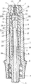
首先参照图1和2,根据本发明医用输液管的阀连接器的第一个实施方式基本上包括一个外部管状体1、轴向位于管状体1的空腔内的空心内销2、和中介弹性密封件3。管状体1和空心销2一般用模制塑性材料制成,同时弹性密封件用弹性材料制成,例如含硅橡胶。Referring first to Figures 1 and 2, a first embodiment of a valve connector for a medical infusion tube according to the present invention basically comprises an outer
外部管状体1具有凹路厄锁定(Luer-Lock)连接件形式的入口端4,以基本上传统的方式与例如由无针注射器构成的引入器的凸Luer或Luer-Lock连接件(其部分在图3和4中示意性地标记为S)配合。附图标记5所指的入口端4的环状内表面可以仅仅是稍为圆锥形的或者也可以是更普通的圆柱形。The outer
管状体1的另一端或出口端成形为凸Luer-Lock连接机构形式,带有稍微锥形外表面7的中央管形套管6和内部的螺纹外覆层7。在图2所示实施方式中,外覆层7与管状体1形成一体;同时,如图8和9所示,内部套管6与空心销2形成一体。在空心销2和内部套管6之间的连接区域设有环状法兰8,该环状法兰8以密封方式连接在管状体1内紧接螺纹覆层7的附近。在如图10和11所示的变型方式中,中央套管6和螺纹覆层7两者都与空心销2形成一体,在这种情况下也形成有环形法兰8用以连接在管状体1中。The other or outlet end of the
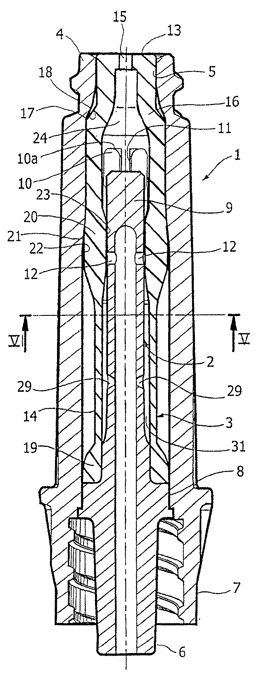
在连接器出口端6,7的相反侧,空心销2具有朝向入口端4并与之有一短的轴向距离的闭合终端9。与某些已知的阀连接器不同,这些已知的阀连接器的空心销自由端具有穿孔顶端,而终端9则形成有轴径向突起10的冠部,突起成角度地相距以在其间限定出外部轴径向流动通道11。所述流动通道11可以在图8、9和10、11,及图7中更清楚地被观察到,除了出口端6、7的结构为图10和11所示而非图8和9所示之外,上述附图所示的流动通道11都与图2所示的相一致,并且为使附图更简单,其中的弹性密封件3被忽略了。On the opposite side of the connector outlet ends 6, 7, the
朝向入口端4的突起10的端面10a优选是平面的或轻度圆形的。The
在离终端9的短距离处,空心销2形成有一个或多个径向的侧孔12,通过该等侧孔,销2的空腔并且因此阀连接器的出口端6、7可以形成与入口端4相连通,其方式详见下文。At a short distance from the
图12和13更清楚地显示,密封弹性件3包括通常为单一件的弹性头部13和弹性空心件14。Figures 12 and 13 show more clearly that the sealing
弹性头部13具有与入口配合件4的内壁5互补的形状,以能够按照图2所示的方式容纳其中,呈有接触而基本上没有干涉的闭合状态,在这种状态下所述头部13基本上是不变形的。或者,当弹性头部13关闭入口端4时,弹性头部在内表面5中基本上不受其挤压。The
贯穿头部13形成预先开出的缝隙或轴向槽口15,在入口端4内的弹性头部13处于非形变闭合状态时,由于头部13的弹性作用,缝隙或轴向槽口15是闭合的。在这种情况下,获得在阀连接器内部与外部之间的抗菌保护屏障,同时也可以进行通常通过浸有消毒剂的软垫进行的有效清洁作业。Through the
头部13接合弹性空心件14通过圆锥平截部16,所述圆锥平截部16的较大基底限定出环形停靠台肩17,在图2所示的非形变密封状态下,该停靠台肩17面对具有锥形表面的内环形台肩18,互补于管状体1。The
所述中空弹性件14在与弹性头部13相对的一侧具有端部唇缘19,该端部唇缘19以密封方式在环形法兰8处紧闭空心销2外壁。弹性空心件14的总体结构可以是波纹状或风箱的形状(如在前述文献US5700248和US6682509中的情况),或者可以更简便地采用简单的圆柱形,具有环形截面(详见图5所示)、椭圆形(详见图6),或者甚至是多边形。在任何情况下,弹性空心件14具有带轻度圆锥外表面21的加厚部分20,以下述方式,该外表面21与管状体1的内壁的互补圆锥表面部分22协同运作。弹性空心件14的部分20的内表面,由附图标记23表示,被设置成与空心销2相接触,并且在入口接头4中的头部13处于非形变闭合情况下,它以密封的方式关闭侧孔12,利用这种方式将弹性头部13、闭合终端9以及围绕终端9的弹性件3的内壁区域之间的腔室24的出口接头6、7隔绝。按照本发明的特别之处,由于在圆锥表面21和22之间相互作用的效果和弹性空心件14的轴向弹性预载作用,实现内壁23圆周径向抵接在空心销2上,保证通过内壁23得到侧孔12密封式闭合。Said hollow
阀连接器的操作描述如下。The operation of the valve connector is described below.
在图2所示的闭合状态下,弹性头部13,如所述的,在入口端4内处于非形变闭合构造时,预先开出的缝隙15保持密封式闭合。弹性空心件14的轴向预载,加上通过管状体1的圆锥表面22正向施加在弹性空心件14的圆锥外表面部分21的径向推压分量的共同作用,正如所述的,使所述空心件14的部分20与空心销2的侧孔12的密封闭合式接触。按照这种方式,阀连接器的入口端4和出口端6、7之间的连通被双重地阻断,一方面是通过处于非形变状态的弹性头部13而产生的进口部4的闭合效果,另一方面是通过弹性空心件14的部分20闭塞孔12。In the closed state shown in FIG. 2 , the
当无针注射器S的末端前面与弹性头部13以密封方式连接,然后插入到进口部4中,按如图3所示的方式,通过弹性空心件14的压缩或轴向收缩作用,弹性头部13被轴向推向连接器内部。同时,弹性空心件14的部分20沿着空心销3向出口部6、7滑动,打开侧孔12从而与腔室24相连通。When the front of the end of the needle-free syringe S is connected with the
表面5被特意设计成可变形的并以密封方式容纳于注射器S的圆锥形表面中,其形状为圆柱形或具有较小锥度的锥形。The
持续推进无针注射器S直至它完全锁住Luer-Lock对进口部4的连接,该阀连接器采用如图4所示的接头:弹性空心件14的额外轴向压缩允许头部13向前移动到中空体1的内部直到它的前部顶到终端9,从而与其突起10相互作用。通过所述的相互作用,头部13呈现弹性形变,也就是径向向外膨胀的构型,用这种方式以打开预先开出的缝隙15。按照这种方式,进口部4,或无针注射器S,被设置成通过腔室24、终端9上的通道11、侧孔12以及空心销2的空腔与出口部6、7相连通。Continue to advance the needle-free syringe S until it fully locks the Luer-Lock connection to the
当无针注射器S从进口部4拔出,弹性密封3的空心件14的弹性恢复迅速还原成图2所示的密封结构,其中弹性头部13在进口部4恢复至非形变状态,进口部4也接着弹性地恢复至非形变状态,并且侧孔12被弹性空心件14的部件20重新关闭。When the needle-free syringe S is pulled out from the
图14至16显示了根据本发明前述内容中参照图2至4所描述的3种操作状态下的阀连接器的变型方式。在该变型中,与已在上面进行描述的相同或相似部件采用相同的数字标记。Figures 14 to 16 show variants of the valve connector in the three operating states described above with reference to Figures 2 to 4 of the present invention. In this variant, identical or similar parts to those already described above bear the same numerals.
实际上,该变型仅仅包括这一事实即空心销2在侧孔12处形成具有环形凹陷或喉部25,其或多或少轴向延伸一长度,在进口部4内的弹性头13处于非形变密封状态下,接合入弹性密封件3的弹性空心件14中加厚的部分20中。在该变型方式中,由于无针注射器S插入到进口部4以及随之发生的弹性空心件14的轴向压缩,部件20沿着空心销2逐渐向出口部6、7移动,从而打开侧孔12。如图16所示,在头部13由于与终端9的突起10相互作用而产生的弹性形变的影响下,然后进口部4与出口部6、7之间的流体通路通过开放的预先开出的缝隙15、腔室24、流动通道11、孔12以及空心销2的空腔而打开。In fact, this variant consists only of the fact that the
图17显示了在如图14所示的密闭状态下弹性空心件14的部件20对孔12形成密闭的细节。FIG. 17 shows details of the sealing of the
图18和19显示了本发明所述的阀连接器的另一变型方式。在这种变型方式中,与已在前述内容中描述的相同或相似的部件采用相同的数字标记,弹性密封元件3的弹性空心件14的部件20以间接而不是直接的方式实现对空心销2中侧孔12的密闭。也就是说,部件20不与环状喉部25的表面闭合,取而代之的是部件20具有带圆锥表面26的部分,在密封状态下,该部分受压与外部圆锥配合表面27密闭接触以作为与环形凹陷25的连接处。在这种情况下,所述密闭接触可以同时通过弹性空心件14的轴向预载和通过由管状体1的圆锥内表面22所正面推向弹性空心件14的外部圆锥表面21的轴向和径向元件来保证。在该变型方式中,如将在下述内容中描述的,弹性头13的内表面形成管道30的顶部,在头部13处于开放状态时,该顶部确定了将来自注射器S和径向通道11的流体传送入侧孔12的轴向流动通道(例如如图21所示),所述径向通道11限定在空心销2终端9的多个突起10之间。Figures 18 and 19 show another variant of the valve connector of the present invention. In this variant, the
如图20和22所示的其它变型方式,是目前所认为的优选实施方式,其中和已在前述内容所描述的相同或相似的部件用相同数字附图标记,与空心销2的外部圆锥表面27协同操作的弹性空心件14的圆锥内表面26由所述弹性空心件14的内部环状突出28形成。Other variants, as shown in Figures 20 and 22, are currently considered preferred embodiments, wherein the same or similar parts as have been described in the foregoing are given the same numerical references, and the outer conical surface of the
所述的变型方式目前被认为是优选的主要原因是因为,在阀连接器闭合的状态下,内部环状突出28与空心销2的外部圆锥表面27的邻接仍旧是更可靠的,即便在实际使用中接头内部产生真空或过大压力也是如此。The main reason why the described variant is currently considered to be preferred is that, in the closed state of the valve connector, the abutment of the inner
在如上所述的阀连接器所有实施方式中,空心销2可以具有另外的侧孔29,其在轴向上远离侧孔12并具有连通出口部6、7和位于弹性空心件14的部件20与其端部唇缘19之间的内部腔室31的功能。按照该方式,在注射器S的插入过程中,以及在孔12开放后,任何可能滞留在腔室31中的空气能自由地逸出并不会阻止弹性件14的操作。此外,在阀连接器使用的最后,当移除无针注射器S时,重新恢复处于进口部4内的弹性头部的非形变闭合状态以及侧孔12的密闭状态,任何在使用中进入腔室31的液体都被从前述的孔29中排出,从而形成在出口部6、7内形成有利的正向压力作用以便于彻底排出所有已注入的药物。最后,任何来自出口端6、7的流体压力都能在腔室31中被吸收,同时能够加强相互配合的圆锥表面26、27之间的密封性。In all embodiments of the valve connector as described above, the
相对于孔12的通道部分而言,孔29中的通道部分可方便地校准以获得上述结果。The passage portion in
当然,只要不脱离所附权利要求中所限定的本发明的保护范围,结构细节以及实施方式可与在此所阐述和解释的内容有广泛的不同。Of course, structural details and embodiments may vary widely from what has been set forth and explained herein without departing from the scope of the invention as defined in the appended claims.
Claims (22)
Applications Claiming Priority (2)
| Application Number | Priority Date | Filing Date | Title |
|---|---|---|---|
| ITTO2004A000524 | 2004-07-27 | ||
| ITTO20040524 ITTO20040524A1 (en) | 2004-07-27 | 2004-07-27 | VALVE CONNECTOR FOR MEDICAL INFUSION LINES |
Publications (2)
| Publication Number | Publication Date |
|---|---|
| CN101035591A CN101035591A (en) | 2007-09-12 |
| CN100542628C true CN100542628C (en) | 2009-09-23 |
Family
ID=34956274
Family Applications (1)
| Application Number | Title | Priority Date | Filing Date |
|---|---|---|---|
| CNB2005800252069A Expired - Lifetime CN100542628C (en) | 2004-07-27 | 2005-07-13 | Valve connector for medical infusion tubing |
Country Status (13)
| Country | Link |
|---|---|
| US (1) | US7784766B2 (en) |
| EP (1) | EP1773445B1 (en) |
| JP (1) | JP4789938B2 (en) |
| CN (1) | CN100542628C (en) |
| AU (1) | AU2005268551B2 (en) |
| CA (1) | CA2575044C (en) |
| DK (1) | DK1773445T3 (en) |
| ES (1) | ES2596283T3 (en) |
| IT (1) | ITTO20040524A1 (en) |
| PL (1) | PL1773445T3 (en) |
| PT (1) | PT1773445T (en) |
| WO (1) | WO2006013433A1 (en) |
| ZA (1) | ZA200700770B (en) |
Families Citing this family (85)
| Publication number | Priority date | Publication date | Assignee | Title |
|---|---|---|---|---|
| US6695817B1 (en) | 2000-07-11 | 2004-02-24 | Icu Medical, Inc. | Medical valve with positive flow characteristics |
| US7753892B2 (en) * | 2001-11-13 | 2010-07-13 | Nypro Inc. | Anti-drawback medical valve |
| US7837658B2 (en) | 2001-11-13 | 2010-11-23 | Nypro Inc. | Anti-drawback medical valve |
| US7914502B2 (en) | 2003-07-31 | 2011-03-29 | Nypro Inc. | Anti-drawback medical valve |
| HK1077154A2 (en) | 2003-12-30 | 2006-02-03 | Icu Medical, Inc. | Valve assembly |
| AU2005304987B2 (en) | 2004-11-05 | 2011-08-11 | Icu Medical, Inc. | Medical connector having high flow rate characteristics |
| US7998134B2 (en) | 2007-05-16 | 2011-08-16 | Icu Medical, Inc. | Medical connector |
| US20070088293A1 (en) * | 2005-07-06 | 2007-04-19 | Fangrow Thomas F Jr | Medical connector with closeable male luer |
| US7591449B2 (en) * | 2006-02-14 | 2009-09-22 | B. Braun Medical Inc. | Needleless access port valves |
| ITTO20060206A1 (en) * | 2006-03-17 | 2007-09-18 | Borla Ind | VALVE VALVE FOR MEDICAL LINES |
| EP2004274B1 (en) * | 2006-04-11 | 2018-04-04 | Nypro Inc. | Medical valve with moving member and method |
| BRPI0714767A2 (en) | 2006-08-11 | 2013-07-16 | Nypro Inc | Expansion Element Medical Valve |
| DK2086623T3 (en) | 2006-10-25 | 2011-08-15 | Icu Medical Inc | Medical connector |
| US8419713B1 (en) | 2012-08-01 | 2013-04-16 | The University Of Utah Research Foundation | Carrier assembly with caps for medical connectors |
| US8523831B2 (en) | 2009-10-30 | 2013-09-03 | Catheter Connections, Inc. | Disinfecting caps having sealing features and related systems and methods |
| JP4526549B2 (en) * | 2007-04-16 | 2010-08-18 | インドゥストリー・ボルラ・ソシエタ・ペル・アチオニ | Medical line valve connector |
| ITTO20080059A1 (en) | 2008-01-29 | 2009-07-30 | Industrie Borla Spa | VALVE VALVE FOR MEDICAL LINES |
| GB0806440D0 (en) * | 2008-04-09 | 2008-05-14 | Hospitalarios S A De C V Prod | Improvements relating to self-seating connectors |
| ITTO20080381A1 (en) | 2008-05-21 | 2009-11-22 | Industrie Borla Spa | VALVE VALVE FOR MEDICAL LINES |
| US7905873B2 (en) * | 2008-07-03 | 2011-03-15 | Baxter International Inc. | Port assembly for use with needleless connector |
| US8172823B2 (en) * | 2008-07-03 | 2012-05-08 | Baxter International Inc. | Port assembly for use with needleless connector |
| US8062280B2 (en) * | 2008-08-19 | 2011-11-22 | Baxter Healthcare S.A. | Port assembly for use with needleless connector |
| US9078992B2 (en) | 2008-10-27 | 2015-07-14 | Pursuit Vascular, Inc. | Medical device for applying antimicrobial to proximal end of catheter |
| US8679090B2 (en) | 2008-12-19 | 2014-03-25 | Icu Medical, Inc. | Medical connector with closeable luer connector |
| US9168366B2 (en) | 2008-12-19 | 2015-10-27 | Icu Medical, Inc. | Medical connector with closeable luer connector |
| US8454579B2 (en) * | 2009-03-25 | 2013-06-04 | Icu Medical, Inc. | Medical connector with automatic valves and volume regulator |
| US8394080B2 (en) * | 2009-05-14 | 2013-03-12 | Baxter International Inc. | Needleless connector with slider |
| CN102481445B (en) | 2009-06-22 | 2014-11-26 | Np医药公司 | Medical valve with improved back-pressure sealing |
| US8231587B2 (en) | 2009-10-30 | 2012-07-31 | Catheter Connections | Disinfecting caps for medical male luer connectors |
| WO2011066565A1 (en) | 2009-11-30 | 2011-06-03 | Catheter Connections, Inc. | Disinfecting caps having an extendable feature and related systems and methods |
| USD644731S1 (en) * | 2010-03-23 | 2011-09-06 | Icu Medical, Inc. | Medical connector |
| US8298196B1 (en) * | 2010-03-24 | 2012-10-30 | Mansour George M | Needleless access connector and method of use |
| DK2550058T3 (en) | 2010-05-06 | 2014-06-30 | Icu Medical Inc | Medical connector with a closable Luer connector |
| US8758306B2 (en) | 2010-05-17 | 2014-06-24 | Icu Medical, Inc. | Medical connectors and methods of use |
| US9138572B2 (en) | 2010-06-24 | 2015-09-22 | Np Medical Inc. | Medical valve with fluid volume alteration |
| US11628267B2 (en) | 2010-08-04 | 2023-04-18 | Medline Industries, Lp | Universal medical gas delivery system |
| USD674895S1 (en) * | 2010-08-04 | 2013-01-22 | Darren Rubin | Secure bushing and connector for universal medical gas delivery |
| EP2469146B1 (en) * | 2010-12-21 | 2017-08-30 | CareFusion Corporation | Connector part and fluid connection structure |
| US10016587B2 (en) | 2011-05-20 | 2018-07-10 | Excelsior Medical Corporation | Caps for needleless connectors |
| JP6140916B2 (en) * | 2011-06-08 | 2017-06-07 | 株式会社ジェイ・エム・エス | Medical male parts |
| EP3714932A1 (en) | 2011-07-12 | 2020-09-30 | ICU Medical, Inc. | Device for delivery of antimicrobial agent into a transdermal catheter |
| EP3760275A1 (en) | 2011-09-09 | 2021-01-06 | ICU Medical, Inc. | Medical connectors with fluid-resistant mating interfaces |
| ITTO20120056A1 (en) * | 2012-01-24 | 2013-07-25 | Borla Ind | CONNECTOR FOR MEDICAL LINES OF INFUSION, TRANSFUSION AND THE LIKE |
| US9114244B2 (en) * | 2012-01-27 | 2015-08-25 | Carefusion 303, Inc. | Needleless valve system fluid control |
| DE202012007845U1 (en) * | 2012-08-17 | 2013-11-19 | B. Braun Melsungen Ag | catheter coupling |
| FR3001393B1 (en) | 2013-01-31 | 2015-01-23 | Ace Dev Solution | IMPROVED MEDICAL CONNECTOR |
| US9144672B2 (en) | 2013-03-13 | 2015-09-29 | Carefusion 303, Inc. | Needleless connector with compressible valve |
| US9089682B2 (en) | 2013-03-14 | 2015-07-28 | Carefusion 303, Inc. | Needleless connector with support member |
| CN104096283B (en) * | 2013-04-12 | 2017-09-19 | 蔡溪进 | Needle-free infusion joint for preventing liquid medicine from leaking |
| ITTO20130433A1 (en) * | 2013-05-29 | 2014-11-30 | Borla Ind | CONNECTOR FOR MEDICAL LINES |
| AU2014364218B2 (en) | 2013-12-11 | 2019-06-06 | Icu Medical, Inc. | Check valve |
| KR200473750Y1 (en) | 2014-04-17 | 2014-07-24 | 윤석주 | Needle free type injection connecter for medical |
| KR200472824Y1 (en) | 2014-04-29 | 2014-05-22 | 윤석주 | Needle-free medical injection connector |
| WO2015168677A1 (en) | 2014-05-02 | 2015-11-05 | Excelsior Medical Corporation | Strip package for antiseptic cap |
| US11628288B1 (en) | 2014-07-14 | 2023-04-18 | Merit Medical Systems, Inc. | Disinfecting cap for needleless injection sites |
| US10166339B2 (en) | 2014-11-24 | 2019-01-01 | Merit Medical Systems, Inc. | Disinfecting cap for medical connectors |
| USD786427S1 (en) | 2014-12-03 | 2017-05-09 | Icu Medical, Inc. | Fluid manifold |
| USD793551S1 (en) | 2014-12-03 | 2017-08-01 | Icu Medical, Inc. | Fluid manifold |
| TWI584837B (en) * | 2015-02-09 | 2017-06-01 | 怡安醫療器材股份有限公司 | Needleless luer access connector module |
| CN104697834B (en) * | 2015-03-24 | 2018-01-02 | 中国地质科学院水文地质环境地质研究所 | A kind of underground water volatile organic matter pre-treatment integrated apparatus |
| ES3040274T3 (en) | 2015-05-08 | 2025-10-29 | Icu Medical Inc | Medical connectors configured to receive emitters of therapeutic agents |
| EP3297596B1 (en) * | 2015-05-22 | 2025-01-01 | Fresenius Kabi Deutschland GmbH | Connection assembly for guiding a medical liquid |
| US11883364B2 (en) | 2015-05-22 | 2024-01-30 | Fresenius Kabi Deutschland Gmbh | Connection assembly for directing a medical liquid |
| JP6543511B2 (en) * | 2015-05-29 | 2019-07-10 | 株式会社ハイレックスコーポレーション | Connection structure |
| AU367143S (en) * | 2015-08-05 | 2016-02-15 | Borla Ind | Valved connector for medical lines |
| EP3377420A4 (en) | 2015-11-16 | 2019-07-10 | Merit Medical Systems, Inc. | DISINFECTION CAP FOR LUER MALE |
| US10744316B2 (en) | 2016-10-14 | 2020-08-18 | Icu Medical, Inc. | Sanitizing caps for medical connectors |
| CN106581789B (en) * | 2016-12-12 | 2023-05-26 | 武汉维斯第医用科技股份有限公司 | External multi-pipeline converter for negative pressure closed drainage system |
| US10603481B2 (en) | 2017-01-27 | 2020-03-31 | Merit Medical Systems, Inc. | Disinfecting luer cap and method of use |
| WO2018204206A2 (en) | 2017-05-01 | 2018-11-08 | Icu Medical, Inc. | Medical fluid connectors and methods for providing additives in medical fluid lines |
| DE102017210795A1 (en) * | 2017-06-27 | 2018-12-27 | B. Braun Melsungen Ag | Medical fluid connection device |
| WO2019070878A1 (en) | 2017-10-04 | 2019-04-11 | Merit Medical Systems, Inc. | Disinfecting cap for valved connectors and method of use |
| US11541220B2 (en) | 2018-11-07 | 2023-01-03 | Icu Medical, Inc. | Needleless connector with antimicrobial properties |
| US11400195B2 (en) | 2018-11-07 | 2022-08-02 | Icu Medical, Inc. | Peritoneal dialysis transfer set with antimicrobial properties |
| US11517732B2 (en) | 2018-11-07 | 2022-12-06 | Icu Medical, Inc. | Syringe with antimicrobial properties |
| US11541221B2 (en) | 2018-11-07 | 2023-01-03 | Icu Medical, Inc. | Tubing set with antimicrobial properties |
| US11534595B2 (en) | 2018-11-07 | 2022-12-27 | Icu Medical, Inc. | Device for delivering an antimicrobial composition into an infusion device |
| WO2020105690A1 (en) * | 2018-11-20 | 2020-05-28 | ニプロ株式会社 | Male connector |
| EP3883638A1 (en) | 2018-11-21 | 2021-09-29 | ICU Medical, Inc. | Antimicrobial device comprising a cap with ring and insert |
| EP4255552A1 (en) | 2020-12-07 | 2023-10-11 | ICU Medical, Inc. | Peritoneal dialysis caps, systems and methods |
| CN113558974B (en) * | 2020-12-07 | 2025-01-21 | 刘云虎 | A positive and negative pressure needle-free rubber valve connector |
| CN114635771B (en) * | 2022-02-24 | 2023-05-16 | 北汽福田汽车股份有限公司 | Urea injection pipe joint seat, urea injection pipeline structure and vehicle |
| US11828388B2 (en) | 2022-03-08 | 2023-11-28 | B. Braun Medical Inc. | Needle-free connector |
| IT202300006996A1 (en) * | 2023-04-12 | 2024-10-12 | Borla Ind | Valve connector for medical lines |
| USD1105422S1 (en) | 2024-02-09 | 2025-12-09 | Icu Medical, Inc. | Medical connector cover |
Citations (4)
| Publication number | Priority date | Publication date | Assignee | Title |
|---|---|---|---|---|
| US6079432A (en) * | 1996-07-02 | 2000-06-27 | Paradis; Joseph R. | Control of fluid flow by oval shaped valve member containing a cam interface |
| US6206861B1 (en) * | 1995-03-10 | 2001-03-27 | Critical Device Corporation | Needleless injection site |
| US20030098430A1 (en) * | 2001-11-29 | 2003-05-29 | Leinsing Karl R. | Needle free medical connector with expanded valve mechanism and method of fluid flow control |
| US6682509B2 (en) * | 1991-12-18 | 2004-01-27 | Icu Medical, Inc. | Medical valve and method of use |
Family Cites Families (10)
| Publication number | Priority date | Publication date | Assignee | Title |
|---|---|---|---|---|
| US5242393A (en) * | 1992-06-18 | 1993-09-07 | Becton, Dickinson And Company | Valved blunt cannula injection site |
| US5700248A (en) * | 1995-12-15 | 1997-12-23 | Icu Medical, Inc. | Medical valve with tire seal |
| US5738663A (en) * | 1995-12-15 | 1998-04-14 | Icu Medical, Inc. | Medical valve with fluid escape space |
| US5807348A (en) * | 1996-11-27 | 1998-09-15 | Elcam Plastics | Needleless valve |
| US6755391B2 (en) * | 2000-10-23 | 2004-06-29 | Nypro Inc. | Anti-drawback medical valve |
| US6964406B2 (en) * | 2001-08-10 | 2005-11-15 | Alaris Medical Systems, Inc. | Valved male luer |
| JP2003305129A (en) * | 2002-04-15 | 2003-10-28 | Koji Karasawa | Lateral injection pipe |
| US7244249B2 (en) * | 2002-05-08 | 2007-07-17 | Cardinal Health 303, Inc. | Needle-free medical connector with expandable valve mechanism and method of fluid flow control |
| US7914502B2 (en) * | 2003-07-31 | 2011-03-29 | Nypro Inc. | Anti-drawback medical valve |
| EP1502613A1 (en) | 2003-08-01 | 2005-02-02 | Novo Nordisk A/S | Needle device with retraction means |
-
2004
- 2004-07-27 IT ITTO20040524 patent/ITTO20040524A1/en unknown
-
2005
- 2005-07-13 US US11/572,747 patent/US7784766B2/en active Active
- 2005-07-13 JP JP2007523169A patent/JP4789938B2/en not_active Expired - Lifetime
- 2005-07-13 CA CA 2575044 patent/CA2575044C/en not_active Expired - Lifetime
- 2005-07-13 PL PL05771868T patent/PL1773445T3/en unknown
- 2005-07-13 EP EP05771868.6A patent/EP1773445B1/en not_active Expired - Lifetime
- 2005-07-13 WO PCT/IB2005/002206 patent/WO2006013433A1/en not_active Ceased
- 2005-07-13 ES ES05771868.6T patent/ES2596283T3/en not_active Expired - Lifetime
- 2005-07-13 PT PT57718686T patent/PT1773445T/en unknown
- 2005-07-13 DK DK05771868.6T patent/DK1773445T3/en active
- 2005-07-13 AU AU2005268551A patent/AU2005268551B2/en not_active Expired
- 2005-07-13 CN CNB2005800252069A patent/CN100542628C/en not_active Expired - Lifetime
-
2007
- 2007-01-26 ZA ZA200700770A patent/ZA200700770B/en unknown
Patent Citations (4)
| Publication number | Priority date | Publication date | Assignee | Title |
|---|---|---|---|---|
| US6682509B2 (en) * | 1991-12-18 | 2004-01-27 | Icu Medical, Inc. | Medical valve and method of use |
| US6206861B1 (en) * | 1995-03-10 | 2001-03-27 | Critical Device Corporation | Needleless injection site |
| US6079432A (en) * | 1996-07-02 | 2000-06-27 | Paradis; Joseph R. | Control of fluid flow by oval shaped valve member containing a cam interface |
| US20030098430A1 (en) * | 2001-11-29 | 2003-05-29 | Leinsing Karl R. | Needle free medical connector with expanded valve mechanism and method of fluid flow control |
Also Published As
| Publication number | Publication date |
|---|---|
| US20080190485A1 (en) | 2008-08-14 |
| CN101035591A (en) | 2007-09-12 |
| ES2596283T3 (en) | 2017-01-05 |
| JP4789938B2 (en) | 2011-10-12 |
| US7784766B2 (en) | 2010-08-31 |
| AU2005268551B2 (en) | 2011-04-28 |
| CA2575044C (en) | 2013-02-19 |
| ITTO20040524A1 (en) | 2004-10-27 |
| JP2008508016A (en) | 2008-03-21 |
| CA2575044A1 (en) | 2006-02-09 |
| ZA200700770B (en) | 2008-09-25 |
| WO2006013433A1 (en) | 2006-02-09 |
| PL1773445T3 (en) | 2017-02-28 |
| PT1773445T (en) | 2016-11-16 |
| AU2005268551A1 (en) | 2006-02-09 |
| EP1773445B1 (en) | 2016-08-24 |
| EP1773445A1 (en) | 2007-04-18 |
| DK1773445T3 (en) | 2016-11-28 |
Similar Documents
| Publication | Publication Date | Title |
|---|---|---|
| CN100542628C (en) | Valve connector for medical infusion tubing | |
| US7118560B2 (en) | Needleless Luer activated medical connector | |
| US5921264A (en) | Swabbable needleless valve | |
| US6651956B2 (en) | Slit-type swabable valve | |
| US7645274B2 (en) | Self-sealing male luer connector with multiple seats | |
| EP2331191B1 (en) | Closed male luer device for minimizing leakage during connection and disconnection | |
| KR101227399B1 (en) | Valved male luer connector having sequential valve timing | |
| US6117114A (en) | Swabbable needleless valve adaptations | |
| AU2002359895A1 (en) | Slit-type swabable valve | |
| HK1245686A1 (en) | Catheter assemblies with flow control valve mechanisms and related methods | |
| JP4526549B2 (en) | Medical line valve connector | |
| AU2011211445A1 (en) | Self-sealing male luer connector with multiple seals |
Legal Events
| Date | Code | Title | Description |
|---|---|---|---|
| C06 | Publication | ||
| PB01 | Publication | ||
| C10 | Entry into substantive examination | ||
| SE01 | Entry into force of request for substantive examination | ||
| C14 | Grant of patent or utility model | ||
| GR01 | Patent grant | ||
| CX01 | Expiry of patent term | ||
| CX01 | Expiry of patent term |
Granted publication date: 20090923 |