CN100513316C - Indium oxide-tin oxide powder and sputtering target using the same - Google Patents
Indium oxide-tin oxide powder and sputtering target using the same Download PDFInfo
- Publication number
- CN100513316C CN100513316C CNB2004800410617A CN200480041061A CN100513316C CN 100513316 C CN100513316 C CN 100513316C CN B2004800410617 A CNB2004800410617 A CN B2004800410617A CN 200480041061 A CN200480041061 A CN 200480041061A CN 100513316 C CN100513316 C CN 100513316C
- Authority
- CN
- China
- Prior art keywords
- powder
- sno
- ito
- tin oxide
- indium oxide
- Prior art date
- Legal status (The legal status is an assumption and is not a legal conclusion. Google has not performed a legal analysis and makes no representation as to the accuracy of the status listed.)
- Expired - Fee Related
Links
Images


Classifications
-
- C—CHEMISTRY; METALLURGY
- C01—INORGANIC CHEMISTRY
- C01G—COMPOUNDS CONTAINING METALS NOT COVERED BY SUBCLASSES C01D OR C01F
- C01G19/00—Compounds of tin
-
- C—CHEMISTRY; METALLURGY
- C01—INORGANIC CHEMISTRY
- C01G—COMPOUNDS CONTAINING METALS NOT COVERED BY SUBCLASSES C01D OR C01F
- C01G15/00—Compounds of gallium, indium or thallium
-
- C—CHEMISTRY; METALLURGY
- C04—CEMENTS; CONCRETE; ARTIFICIAL STONE; CERAMICS; REFRACTORIES
- C04B—LIME, MAGNESIA; SLAG; CEMENTS; COMPOSITIONS THEREOF, e.g. MORTARS, CONCRETE OR LIKE BUILDING MATERIALS; ARTIFICIAL STONE; CERAMICS; REFRACTORIES; TREATMENT OF NATURAL STONE
- C04B35/00—Shaped ceramic products characterised by their composition; Ceramics compositions; Processing powders of inorganic compounds preparatory to the manufacturing of ceramic products
- C04B35/01—Shaped ceramic products characterised by their composition; Ceramics compositions; Processing powders of inorganic compounds preparatory to the manufacturing of ceramic products based on oxide ceramics
- C04B35/453—Shaped ceramic products characterised by their composition; Ceramics compositions; Processing powders of inorganic compounds preparatory to the manufacturing of ceramic products based on oxide ceramics based on zinc, tin, or bismuth oxides or solid solutions thereof with other oxides, e.g. zincates, stannates or bismuthates
- C04B35/457—Shaped ceramic products characterised by their composition; Ceramics compositions; Processing powders of inorganic compounds preparatory to the manufacturing of ceramic products based on oxide ceramics based on zinc, tin, or bismuth oxides or solid solutions thereof with other oxides, e.g. zincates, stannates or bismuthates based on tin oxides or stannates
-
- C—CHEMISTRY; METALLURGY
- C04—CEMENTS; CONCRETE; ARTIFICIAL STONE; CERAMICS; REFRACTORIES
- C04B—LIME, MAGNESIA; SLAG; CEMENTS; COMPOSITIONS THEREOF, e.g. MORTARS, CONCRETE OR LIKE BUILDING MATERIALS; ARTIFICIAL STONE; CERAMICS; REFRACTORIES; TREATMENT OF NATURAL STONE
- C04B35/00—Shaped ceramic products characterised by their composition; Ceramics compositions; Processing powders of inorganic compounds preparatory to the manufacturing of ceramic products
- C04B35/622—Forming processes; Processing powders of inorganic compounds preparatory to the manufacturing of ceramic products
- C04B35/626—Preparing or treating the powders individually or as batches ; preparing or treating macroscopic reinforcing agents for ceramic products, e.g. fibres; mechanical aspects section B
- C04B35/62605—Treating the starting powders individually or as mixtures
- C04B35/62645—Thermal treatment of powders or mixtures thereof other than sintering
- C04B35/62665—Flame, plasma or melting treatment
-
- C—CHEMISTRY; METALLURGY
- C23—COATING METALLIC MATERIAL; COATING MATERIAL WITH METALLIC MATERIAL; CHEMICAL SURFACE TREATMENT; DIFFUSION TREATMENT OF METALLIC MATERIAL; COATING BY VACUUM EVAPORATION, BY SPUTTERING, BY ION IMPLANTATION OR BY CHEMICAL VAPOUR DEPOSITION, IN GENERAL; INHIBITING CORROSION OF METALLIC MATERIAL OR INCRUSTATION IN GENERAL
- C23C—COATING METALLIC MATERIAL; COATING MATERIAL WITH METALLIC MATERIAL; SURFACE TREATMENT OF METALLIC MATERIAL BY DIFFUSION INTO THE SURFACE, BY CHEMICAL CONVERSION OR SUBSTITUTION; COATING BY VACUUM EVAPORATION, BY SPUTTERING, BY ION IMPLANTATION OR BY CHEMICAL VAPOUR DEPOSITION, IN GENERAL
- C23C14/00—Coating by vacuum evaporation, by sputtering or by ion implantation of the coating forming material
- C23C14/06—Coating by vacuum evaporation, by sputtering or by ion implantation of the coating forming material characterised by the coating material
- C23C14/08—Oxides
- C23C14/086—Oxides of zinc, germanium, cadmium, indium, tin, thallium or bismuth
-
- C—CHEMISTRY; METALLURGY
- C23—COATING METALLIC MATERIAL; COATING MATERIAL WITH METALLIC MATERIAL; CHEMICAL SURFACE TREATMENT; DIFFUSION TREATMENT OF METALLIC MATERIAL; COATING BY VACUUM EVAPORATION, BY SPUTTERING, BY ION IMPLANTATION OR BY CHEMICAL VAPOUR DEPOSITION, IN GENERAL; INHIBITING CORROSION OF METALLIC MATERIAL OR INCRUSTATION IN GENERAL
- C23C—COATING METALLIC MATERIAL; COATING MATERIAL WITH METALLIC MATERIAL; SURFACE TREATMENT OF METALLIC MATERIAL BY DIFFUSION INTO THE SURFACE, BY CHEMICAL CONVERSION OR SUBSTITUTION; COATING BY VACUUM EVAPORATION, BY SPUTTERING, BY ION IMPLANTATION OR BY CHEMICAL VAPOUR DEPOSITION, IN GENERAL
- C23C14/00—Coating by vacuum evaporation, by sputtering or by ion implantation of the coating forming material
- C23C14/22—Coating by vacuum evaporation, by sputtering or by ion implantation of the coating forming material characterised by the process of coating
- C23C14/34—Sputtering
- C23C14/3407—Cathode assembly for sputtering apparatus, e.g. Target
- C23C14/3414—Metallurgical or chemical aspects of target preparation, e.g. casting, powder metallurgy
-
- C—CHEMISTRY; METALLURGY
- C01—INORGANIC CHEMISTRY
- C01P—INDEXING SCHEME RELATING TO STRUCTURAL AND PHYSICAL ASPECTS OF SOLID INORGANIC COMPOUNDS
- C01P2002/00—Crystal-structural characteristics
- C01P2002/70—Crystal-structural characteristics defined by measured X-ray, neutron or electron diffraction data
- C01P2002/72—Crystal-structural characteristics defined by measured X-ray, neutron or electron diffraction data by d-values or two theta-values, e.g. as X-ray diagram
-
- C—CHEMISTRY; METALLURGY
- C01—INORGANIC CHEMISTRY
- C01P—INDEXING SCHEME RELATING TO STRUCTURAL AND PHYSICAL ASPECTS OF SOLID INORGANIC COMPOUNDS
- C01P2004/00—Particle morphology
- C01P2004/80—Particles consisting of a mixture of two or more inorganic phases
- C01P2004/82—Particles consisting of a mixture of two or more inorganic phases two phases having the same anion, e.g. both oxidic phases
-
- C—CHEMISTRY; METALLURGY
- C01—INORGANIC CHEMISTRY
- C01P—INDEXING SCHEME RELATING TO STRUCTURAL AND PHYSICAL ASPECTS OF SOLID INORGANIC COMPOUNDS
- C01P2006/00—Physical properties of inorganic compounds
- C01P2006/12—Surface area
-
- C—CHEMISTRY; METALLURGY
- C04—CEMENTS; CONCRETE; ARTIFICIAL STONE; CERAMICS; REFRACTORIES
- C04B—LIME, MAGNESIA; SLAG; CEMENTS; COMPOSITIONS THEREOF, e.g. MORTARS, CONCRETE OR LIKE BUILDING MATERIALS; ARTIFICIAL STONE; CERAMICS; REFRACTORIES; TREATMENT OF NATURAL STONE
- C04B2235/00—Aspects relating to ceramic starting mixtures or sintered ceramic products
- C04B2235/02—Composition of constituents of the starting material or of secondary phases of the final product
- C04B2235/30—Constituents and secondary phases not being of a fibrous nature
- C04B2235/32—Metal oxides, mixed metal oxides, or oxide-forming salts thereof, e.g. carbonates, nitrates, (oxy)hydroxides, chlorides
- C04B2235/3286—Gallium oxides, gallates, indium oxides, indates, thallium oxides, thallates or oxide forming salts thereof, e.g. zinc gallate
-
- C—CHEMISTRY; METALLURGY
- C04—CEMENTS; CONCRETE; ARTIFICIAL STONE; CERAMICS; REFRACTORIES
- C04B—LIME, MAGNESIA; SLAG; CEMENTS; COMPOSITIONS THEREOF, e.g. MORTARS, CONCRETE OR LIKE BUILDING MATERIALS; ARTIFICIAL STONE; CERAMICS; REFRACTORIES; TREATMENT OF NATURAL STONE
- C04B2235/00—Aspects relating to ceramic starting mixtures or sintered ceramic products
- C04B2235/02—Composition of constituents of the starting material or of secondary phases of the final product
- C04B2235/50—Constituents or additives of the starting mixture chosen for their shape or used because of their shape or their physical appearance
- C04B2235/54—Particle size related information
- C04B2235/5409—Particle size related information expressed by specific surface values
-
- C—CHEMISTRY; METALLURGY
- C04—CEMENTS; CONCRETE; ARTIFICIAL STONE; CERAMICS; REFRACTORIES
- C04B—LIME, MAGNESIA; SLAG; CEMENTS; COMPOSITIONS THEREOF, e.g. MORTARS, CONCRETE OR LIKE BUILDING MATERIALS; ARTIFICIAL STONE; CERAMICS; REFRACTORIES; TREATMENT OF NATURAL STONE
- C04B2235/00—Aspects relating to ceramic starting mixtures or sintered ceramic products
- C04B2235/02—Composition of constituents of the starting material or of secondary phases of the final product
- C04B2235/50—Constituents or additives of the starting mixture chosen for their shape or used because of their shape or their physical appearance
- C04B2235/54—Particle size related information
- C04B2235/5418—Particle size related information expressed by the size of the particles or aggregates thereof
- C04B2235/5436—Particle size related information expressed by the size of the particles or aggregates thereof micrometer sized, i.e. from 1 to 100 micron
-
- C—CHEMISTRY; METALLURGY
- C04—CEMENTS; CONCRETE; ARTIFICIAL STONE; CERAMICS; REFRACTORIES
- C04B—LIME, MAGNESIA; SLAG; CEMENTS; COMPOSITIONS THEREOF, e.g. MORTARS, CONCRETE OR LIKE BUILDING MATERIALS; ARTIFICIAL STONE; CERAMICS; REFRACTORIES; TREATMENT OF NATURAL STONE
- C04B2235/00—Aspects relating to ceramic starting mixtures or sintered ceramic products
- C04B2235/70—Aspects relating to sintered or melt-casted ceramic products
- C04B2235/74—Physical characteristics
- C04B2235/76—Crystal structural characteristics, e.g. symmetry
-
- C—CHEMISTRY; METALLURGY
- C04—CEMENTS; CONCRETE; ARTIFICIAL STONE; CERAMICS; REFRACTORIES
- C04B—LIME, MAGNESIA; SLAG; CEMENTS; COMPOSITIONS THEREOF, e.g. MORTARS, CONCRETE OR LIKE BUILDING MATERIALS; ARTIFICIAL STONE; CERAMICS; REFRACTORIES; TREATMENT OF NATURAL STONE
- C04B2235/00—Aspects relating to ceramic starting mixtures or sintered ceramic products
- C04B2235/70—Aspects relating to sintered or melt-casted ceramic products
- C04B2235/74—Physical characteristics
- C04B2235/77—Density
Landscapes
- Chemical & Material Sciences (AREA)
- Engineering & Computer Science (AREA)
- Organic Chemistry (AREA)
- Materials Engineering (AREA)
- Ceramic Engineering (AREA)
- Mechanical Engineering (AREA)
- Metallurgy (AREA)
- Manufacturing & Machinery (AREA)
- Chemical Kinetics & Catalysis (AREA)
- Inorganic Chemistry (AREA)
- Structural Engineering (AREA)
- Physics & Mathematics (AREA)
- Plasma & Fusion (AREA)
- Thermal Sciences (AREA)
- Compositions Of Oxide Ceramics (AREA)
- Physical Vapour Deposition (AREA)
Abstract
Description
技术领域 technical field
本发明涉及氧化铟-氧化锡粉体,并涉及利用该粉体的溅射靶。The present invention relates to indium oxide-tin oxide powder, and to a sputtering target using the powder.
背景技术 Background technique
溅射是用于形成薄膜的众所周知的技术。在溅射技术中,通过对溅射靶进行溅射而形成薄膜。溅射技术被用于工业加工,因为可以方便地形成大表面积的薄膜,并且能够以高效率形成高性能的膜。近年来,各种溅射技术已为人所知,例如反应溅射;即在反应性气体中的溅射,和磁控溅射,它通过将磁体置于靶的背面实现了高速率的薄膜形成。Sputtering is a well known technique for forming thin films. In sputtering technology, a thin film is formed by sputtering a sputtering target. Sputtering technology is used in industrial processing because it can easily form thin films with large surface area and can form high-performance films with high efficiency. In recent years, various sputtering techniques have been known, such as reactive sputtering; that is, sputtering in a reactive gas, and magnetron sputtering, which achieves a high rate of film formation by placing a magnet on the back side of a target .
在通过溅射得到的薄膜产品之中,氧化铟-氧化锡(In2O3-SnO2复合氧化物,下文中简称为ITO)薄膜,由于对于可见光具有高的光学透明度并具有高的导电性,因此它作为透明导电膜得到了广泛的应用,例如用于液晶显示,用于玻璃的除雾的生热薄膜,和IR反射薄膜。Among the thin film products obtained by sputtering, indium oxide-tin oxide (In 2 O 3 -SnO 2 composite oxide, hereinafter referred to as ITO) thin film, due to its high optical transparency to visible light and high electrical conductivity , so it has been widely used as a transparent conductive film, such as for liquid crystal display, heat generating film for defogging of glass, and IR reflective film.
因此,为了更高效率和更低成本的生产薄膜,需要对溅射条件和溅射设备进行改进和改善,现在仍在进行当中,而且溅射设备的有效操作是必需的。在通过溅射生产ITO薄膜中,从安装新溅射靶到初始电弧(异常放电)结束的时期,即引发薄膜形成所需要的时期,优选尽可能短,并且评价从靶的安装开始的可溅射时期(累计溅射时间:靶寿命)是一个关键问题。Therefore, in order to produce thin films with higher efficiency and lower cost, improvement and improvement of sputtering conditions and sputtering equipment are required, and are still in progress, and efficient operation of sputtering equipment is required. In the production of ITO thin films by sputtering, the period from the installation of a new sputtering target to the end of the initial arc (abnormal discharge), that is, the period required to initiate film formation, is preferably as short as possible, and the sputterability from the installation of the target is evaluated Sputtering period (cumulative sputtering time: target life) is a key issue.
前述用于形成ITO薄膜的溅射靶是通过如下方法制成:以预定比例混合氧化铟粉和氧化锡粉,在干态或湿态下进行成形,然后烧结成形产物(专利文献1)。在这方面,已提出可高度分散的氧化铟粉以生产高密度ITO烧结体(例如参见专利文献2、3和4)。The aforementioned sputtering target for forming an ITO thin film is made by mixing indium oxide powder and tin oxide powder in a predetermined ratio, forming in a dry or wet state, and then sintering the shaped product (Patent Document 1). In this regard, highly dispersible indium oxide powders have been proposed to produce high-density ITO sintered bodies (see, for example,
同时,另一种已知方法包括,烧结在湿态下通过共沉淀方法合成的ITO粉体(例如参见专利文献5)。类似地,已提出多种用于生产ITO粉体的湿合成方法用来生产高密度的烧结ITO(例如参见专利文献6-9)。Meanwhile, another known method includes sintering ITO powder synthesized by a co-precipitation method in a wet state (see, for example, Patent Document 5). Similarly, various wet synthesis methods for producing ITO powders have been proposed to produce high-density sintered ITO (see, for example, patent documents 6-9).
提出了生产ITO粉体的又一种方法,该粉体在氧化铟晶格中包含至少90vol%量的铟锡氧化物固溶体相。该方法中,使铟-锡合金在等离子弧中与氧反应,随后通过马赫数≥1的气流以预定或更快的冷却速率冷却反应产物(参见专利文献10),以便由此获得预定电阻率的ITO粉体生坯。Yet another method for producing ITO powder comprising an indium tin oxide solid solution phase in an amount of at least 90 vol % in an indium oxide lattice is proposed. In this method, an indium-tin alloy is reacted with oxygen in a plasma arc, and then the reaction product is cooled at a predetermined or faster cooling rate by a gas flow with a Mach number ≥ 1 (see Patent Document 10), so as to thereby obtain a predetermined resistivity ITO powder green body.
然而,即使现在,仍存在对能够方便地生产高密度烧结ITO而无需严格控制烧结条件和其它条件的ITO粉体的需求,由此生产长寿命的溅射靶。However, even now, there is still a demand for an ITO powder capable of conveniently producing high-density sintered ITO without strict control of sintering conditions and other conditions, thereby producing a long-life sputtering target.
专利文献1:日本专利申请公开No.62-21751Patent Document 1: Japanese Patent Application Laid-Open No. 62-21751
专利文献2:日本专利申请公开No.5-193939Patent Document 2: Japanese Patent Application Laid-Open No. 5-193939
专利文献3:日本专利申请公开No.6-191846Patent Document 3: Japanese Patent Application Laid-Open No. 6-191846
专利文献4:日本专利申请公开No.2001-261336Patent Document 4: Japanese Patent Application Laid-Open No. 2001-261336
专利文献5:日本专利申请公开No.62-21751Patent Document 5: Japanese Patent Application Laid-Open No. 62-21751
专利文献6:日本专利申请公开No.9-221322Patent Document 6: Japanese Patent Application Laid-Open No. 9-221322
专利文献7:日本专利申请公开No.2000-281337Patent Document 7: Japanese Patent Application Laid-Open No. 2000-281337
专利文献8:日本专利申请公开No.2001-172018Patent Document 8: Japanese Patent Application Publication No. 2001-172018
专利文献9:日本专利申请公开No.2002-68744Patent Document 9: Japanese Patent Application Laid-Open No. 2002-68744
专利文献10:日本专利申请公开No.11-11946Patent Document 10: Japanese Patent Application Laid-Open No. 11-11946
发明内容 Contents of the invention
本发明待解决的问题Problems to be solved by the present invention
在这样的情形下,本发明的一个目的是提供能够以低成本生产的氧化铟-氧化锡粉体,并且该粉体能够提供具有延长靶寿命的高密度溅射靶。本发明的另一个目的是提供利用该粉体的溅射靶。Under such circumstances, an object of the present invention is to provide an indium oxide-tin oxide powder that can be produced at low cost and that can provide a high-density sputtering target with an extended target life. Another object of the present invention is to provide a sputtering target using the powder.
解决问题的方式way to solve the problem
在用于达到前述目的的本发明的第一种方式中,提供了包含In-Sn氧化物作为主要成分的氧化铟-氧化锡粉体,其特征在于该氧化物粉体不包含可通过X射线衍射检测出的复合氧化物(In4Sn3O12),并且在In2O3中具有2.3质量%或更大的SnO2固溶量,该SnO2固溶量是根据In2O3(222)的积分衍射强度与SnO2(110)的积分衍射强度的比值和In2O3含量与SnO2含量的比值计算得到,而In2O3含量与SnO2含量的比值是通过ICP分析由In元素浓度和Sn元素浓度得到。In the first aspect of the present invention for achieving the aforementioned object, there is provided an indium oxide-tin oxide powder containing In—Sn oxide as a main component, characterized in that the oxide powder does not contain The complex oxide (In 4 Sn 3 O 12 ) detected by diffraction, and has a solid solution amount of SnO 2 in In 2 O 3 of 2.3% by mass or more, which is based on In 2 O 3 ( 222) to the integrated diffraction intensity of SnO 2 (110) and the ratio of In 2 O 3 content to SnO 2 content, and the ratio of In 2 O 3 content to SnO 2 content was calculated by ICP analysis from In element concentration and Sn element concentration are obtained.
依照第一种模式,氧化铟包含至少预定量的形成固溶体的氧化锡。因此,该ITO粉体具有高的可烧结性。因而,即使当ITO生坯不具有提高的ITO生坯密度,烧结后的溅射靶仍保持高的密度。According to the first mode, indium oxide contains at least a predetermined amount of tin oxide forming a solid solution. Therefore, the ITO powder has high sinterability. Thus, even when the ITO green body does not have an increased ITO green density, the sintered sputtering target maintains a high density.
本发明的第二种模式可以被描绘成第一种模式的氧化铟-氧化锡粉体的特定实施方案,其中In2O3中的SnO2固溶量是2.4质量%或更大。The second mode of the present invention can be described as a specific embodiment of the indium oxide-tin oxide powder of the first mode, wherein the solid solution amount of SnO 2 in In 2 O 3 is 2.4% by mass or more.
依照第二种模式,氧化铟包含大量形成固溶体的氧化锡。因此,该ITO粉体具有更高的可烧结性。According to the second mode, indium oxide contains a large amount of tin oxide forming a solid solution. Therefore, the ITO powder has higher sinterability.
本发明的第三种模式可以被描绘成第一或第二种模式的氧化铟-氧化锡粉体的特定实施方案,该粉体具有基于SnO2计算得到的2.3至45质量%的锡含量。The third mode of the present invention can be described as a specific embodiment of the indium oxide-tin oxide powder of the first or second mode, the powder having a tin content of 2.3 to 45% by mass calculated based on SnO 2 .
依照第三种模式,基于SnO2计算的锡含量至少为2.3质量%,因为In2O3中的SnO2固溶量至少为2.3质量%。当锡含量超过例如45质量%时,SnO2会沉积在溅射利用ITO粉体的靶所形成的薄膜中,从而降低该薄膜的导电性。According to the third mode, the tin content calculated based on SnO 2 is at least 2.3% by mass because the amount of SnO 2 solid-solubilized in In 2 O 3 is at least 2.3% by mass. When the tin content exceeds, for example, 45% by mass, SnO 2 is deposited in a thin film formed by sputtering a target using ITO powder, thereby reducing the conductivity of the thin film.
本发明的第四种模式可以被描述成第一至第三种模式任何一个的氧化铟-氧化锡粉体的特定实施方案,通过如下方式生产该粉体:向作为热源的氧化气氛中供入液流、液滴或粉体形式的铟-锡合金或者ITO粉体;并通过流体捕集和收集微粒形式的产物。The fourth mode of the present invention can be described as a specific embodiment of the indium oxide-tin oxide powder of any one of the first to third modes, which is produced by supplying Indium-tin alloy or ITO powder in the form of streams, droplets, or powder; and capture and collection of the product in particulate form by the fluid.
依照第四种模式,将液流、液滴或粉体形式的铟-锡合金供入作为热源的氧化气氛中,并通过流体捕集和收集形成的微粒。因此,可以通过相对简单的方法生产ITO粉体。According to a fourth mode, the indium-tin alloy in the form of a liquid stream, liquid droplets or powder is fed into an oxidizing atmosphere as a heat source, and the formed particles are captured and collected by the fluid. Therefore, ITO powder can be produced by a relatively simple method.
本发明的第五种模式可以被描述成第四种模式的氧化铟-氧化锡粉体的特定实施方案,其中该流体是雾状液体流体。A fifth mode of the present invention can be described as a specific embodiment of the indium oxide-tin oxide powder of the fourth mode, wherein the fluid is a mist-like liquid fluid.
依照第五种模式,可以通过雾状液体流体方便地收集微粒。According to the fifth mode, the particles can be conveniently collected by the mist liquid fluid.
本发明的第六种模式可以被描述成第四或第五种模式的氧化铟-氧化锡粉体的特定实施方案,其中当通过液体流体捕集微粒时,形成的微粒以150m/s或更小的最大速度流动。The sixth mode of the present invention can be described as a specific embodiment of the indium oxide-tin oxide powder of the fourth or fifth mode, wherein when the particles are captured by the liquid fluid, the formed particles travel at 150 m/s or more Small maximum speed flow.
依照第六种模式,可以以相对低的速度冷却和收集微粒。因此,可以通过相对简单的方法生产ITO粉体。According to the sixth mode, particles can be cooled and collected at a relatively low rate. Therefore, ITO powder can be produced by a relatively simple method.
在本发明的第七种模式中,提供了溅射靶,其特征在于通过对第一至第六种模式任何一个所述的氧化铟-氧化锡粉体进行烧结生产该靶。In a seventh mode of the present invention, there is provided a sputtering target characterized in that the target is produced by sintering the indium oxide-tin oxide powder described in any one of the first to sixth modes.
依照第七种模式,可以由具有高可烧结性的ITO粉体生产溅射靶。According to the seventh mode, a sputtering target can be produced from ITO powder having high sinterability.
如上文所述,本发明的ITO粉体不包含可通过X射线衍射检测出的复合氧化物(In4Sn3O12),并且在In2O3中具有2.3质量%或更大的SnO2固溶量,该SnO2固溶量是根据In2O3(222)的积分衍射强度与SnO2(110)的积分衍射强度的比值计算和In2O3含量与SnO2含量的比值得到,而In2O3含量与SnO2含量的比值是通过ICP分析由In元素浓度和Sn元素浓度得到。因此,该ITO粉体具有高的可烧结性,并且即使当ITO生坯不具有提高的ITO生坯密度时,也能够容易地生产高密度的溅射靶As described above, the ITO powder of the present invention does not contain a composite oxide (In 4 Sn 3 O 12 ) detectable by X-ray diffraction, and has 2.3% by mass or more of SnO 2 in In 2 O 3 Solid solution amount, the SnO 2 solid solution amount is calculated according to the ratio of the integral diffraction intensity of In 2 O 3 (222) to the integral diffraction intensity of SnO 2 (110) and the ratio of In 2 O 3 content to SnO 2 content, The ratio of the In 2 O 3 content to the SnO 2 content is obtained from the In element concentration and the Sn element concentration through ICP analysis. Therefore, the ITO powder has high sinterability, and can easily produce high-density sputtering targets even when the ITO green body does not have an increased ITO green body density.
图1:生产用于形成本发明ITO粉体的微粒的设备的一个实施方案的示意布局。Figure 1: Schematic layout of one embodiment of an apparatus for producing microparticles used to form the ITO powder of the present invention.
图2:本发明实施例1中生产的ITO粉体的X射线衍射图。Figure 2: X-ray diffraction pattern of the ITO powder produced in Example 1 of the present invention.
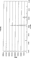
图3:本发明实施例2中生产的ITO粉体的X射线衍射图。Figure 3: X-ray diffraction pattern of the ITO powder produced in Example 2 of the present invention.
图4:本发明比较例1中生产的ITO粉体的X射线衍射图。Figure 4: X-ray diffraction pattern of the ITO powder produced in Comparative Example 1 of the present invention.
图5:本发明比较例2中生产的ITO粉体的X射线衍射图。Figure 5: X-ray diffraction pattern of the ITO powder produced in Comparative Example 2 of the present invention.
图6:本发明比较例3中生产的ITO粉体的X射线衍射图。Figure 6: X-ray diffraction pattern of the ITO powder produced in Comparative Example 3 of the present invention.
图7:本发明实施例3中生产的ITO粉体的X射线衍射图。Figure 7: X-ray diffraction pattern of the ITO powder produced in Example 3 of the present invention.
图8:本发明比较例4中生产的ITO粉体的X射线衍射图。Figure 8: X-ray diffraction pattern of the ITO powder produced in Comparative Example 4 of the present invention.
实施本发明的最佳模式Best Mode for Carrying Out the Invention
本发明的ITO粉体是包含In-Sn氧化物作为主要成分的氧化铟-氧化锡粉体,该粉体不包含可通过X射线衍射检测出的复合氧化物(In4Sn3O12)。在下面的ITO粉体中检测到复合氧化物(In4Sn13O12):对在1250℃或更高温度下烧结ITO粉体形成的产物进行粉碎得到的ITO粉体,和对烧结氧化铟粉体和氧化锡粉体的混合物形成的产物进行粉碎得到的ITO粉体。不言而喻,这样的粉体不在本发明的范围之内。The ITO powder of the present invention is an indium oxide-tin oxide powder containing In—Sn oxide as a main component, and the powder does not contain a composite oxide (In 4 Sn 3 O 12 ) detectable by X-ray diffraction. Composite oxide (In 4 Sn 13 O 12 ) was detected in the following ITO powders: ITO powder obtained by pulverizing the product formed by sintering ITO powder at 1250°C or higher, and sintered indium oxide The ITO powder obtained by pulverizing the product formed by the mixture of powder and tin oxide powder. It goes without saying that such powders are not within the scope of the present invention.
另外,本发明的ITO粉体在In2O3中具有2.3质量%或更多的SnO2固溶量,优选2.4质量%或更多,该SnO2固溶量是根据In2O3(222)的积分衍射强度与SnO2(11O)的积分衍射强度的比值和In2O3含量与SnO2含量的比值计算得到,而In2O3含量与SnO2含量的比值是通过ICP分析由In元素浓度和Sn元素浓度得到。这里所用的“SnO2固溶量”可以由In2O3(222)的积分衍射强度与SnO2(110)的积分衍射强度的比值和In2O3含量与SnO2含量的比值,通过计算这两个比值之间的差而得到,而In2O3含量与SnO2含量的比值是通过例如对熔融产物的分析或感应耦合等离子分光分析(ICP分光分析)等的分析由In元素浓度和Sn元素浓度得到。本发明中,将SnO2固溶量定义为根据In2O3(222)的积分衍射强度与SnO2(110)的积分衍射强度的比值和In2O3含量与SnO2含量的比值计算得到,而In2O3含量与SnO2含量的比值是通过ICP分析由In元素浓度和Sn元素浓度得到。In addition, the ITO powder of the present invention has a solid solution amount of SnO 2 in In 2 O 3 of 2.3% by mass or more, preferably 2.4% by mass or more, and the amount of SnO 2 solid solution is based on In 2 O 3 (222 ) to the integrated diffraction intensity of SnO 2 (11O) and the ratio of In 2 O 3 content to SnO 2 content were calculated, while the ratio of In 2 O 3 content to SnO 2 content was obtained by ICP analysis from In Element concentration and Sn element concentration are obtained. The "SnO 2 solid solution amount" used here can be calculated by the ratio of the integrated diffraction intensity of In 2 O 3 (222) to the integrated diffraction intensity of SnO 2 (110) and the ratio of In 2 O 3 content to SnO 2 content. The difference between these two ratios is obtained, while the ratio of the In2O3 content to the SnO2 content is determined by the In element concentration and Sn element concentration is obtained. In the present invention, the amount of solid solution of SnO2 is defined as calculated according to the ratio of the integral diffraction intensity of In2O3 (222) to the integral diffraction intensity of SnO2 (110 ) and the ratio of In2O3 content to SnO2 content , and the ratio of the In 2 O 3 content to the SnO 2 content was obtained from the In element concentration and the Sn element concentration by ICP analysis.
当In2O3中的SnO2固溶量为2.3质量%或更多,优选2.4质量或更多时,该ITO粉体与通过湿法合成得到的常规ITO粉体相比具有更高的可烧结性。因此,本发明的ITO粉体可以生产高密度的烧结ITO。When the solid solution amount of SnO2 in In2O3 is 2.3% by mass or more, preferably 2.4% by mass or more, the ITO powder has higher reliability than conventional ITO powder obtained by wet synthesis. Sinterability. Therefore, the ITO powder of the present invention can produce high-density sintered ITO.
前述专利文献10公开了,氧化铟晶格中铟-锡氧化物固溶体相的量至少为90Vol%。然而,在本发明中,使用固溶在氧化铟中的氧化锡量而非氧化铟晶格中的铟-锡氧化物固溶体相的量。The
本发明的ITO粉体包含大量溶解在In2O3中的SnO2固溶体成分。因此,该ITO粉体表现出高的可烧结性并易于提供高密度的烧结ITO。结果,可以生产长寿命的溅射靶。The ITO powder of the present invention contains a large amount of SnO 2 solid solution components dissolved in In 2 O 3 . Therefore, the ITO powder exhibits high sinterability and is easy to provide high-density sintered ITO. As a result, long-life sputtering targets can be produced.
基于SnO2计算,本发明的ITO粉体具有2.3至45质量%的锡含量。由于In2O3中的SnO2固溶量至少为2.3质量%,因此基于SnO2计算锡的含量至少为2.3质量%。现反,当锡含量超过例如45质量%时,例如,SnO2会沉积在通过溅射利用该ITO粉体的靶形成的薄膜中,从而降低薄膜的导电性。不言而喻,这两种情形都不优选。Based on SnO2 calculation, the ITO powder of the present invention has a tin content of 2.3 to 45% by mass. Since the solid solution amount of SnO 2 in In 2 O 3 is at least 2.3% by mass, the content of tin calculated based on SnO 2 is at least 2.3% by mass. On the other hand, when the tin content exceeds, for example, 45% by mass, for example, SnO 2 is deposited in a thin film formed by sputtering using the ITO powder target, thereby reducing the conductivity of the thin film. It goes without saying that neither of these cases is preferable.
对生产本发明ITO粉体的方法没有具体的限制,只要生产出满足前述性能的ITO粉体。然而,可以通过干法合成以低的成本方便地生产本发明的ITO粉体。具体地,可以通过如下方法生产ITO粉体:将液流、液滴或粉体形式的In-Sn合金或ITO粉体供入作为热源的氧化气氛(例如乙炔焰或DC等离子焰)中,并收集形成的ITO微粒。可以通过从容器中连续或间断地逐滴倒出熔融金属得到液流或液滴形式的In-Sn合金,而可以通过例如雾化产生In-Sn合金粉体。此外,可以使用通过各种其它方法生产的ITO粉体,或者使用通过粉碎烧结ITO得到的ITO粉体作为原料。可以通过袋滤器或静电沉淀器以干法收集如此生产的ITO超细粉。或者,也可以使用湿法。即,将水喷向ITO超细粉,由此捕集粉体,并通过旋风分离器对混合物进行气-液分离,由此以浆料形式收集粉体。There is no specific limitation on the method of producing the ITO powder of the present invention, as long as the ITO powder satisfying the aforementioned properties is produced. However, the ITO powder of the present invention can be conveniently produced at low cost by dry synthesis. Specifically, the ITO powder can be produced by supplying an In—Sn alloy or ITO powder in the form of a liquid stream, a droplet, or a powder into an oxidizing atmosphere such as an acetylene flame or a DC plasma flame as a heat source, and The ITO particles formed were collected. The In—Sn alloy in the form of a liquid stream or droplets can be obtained by continuously or intermittently pouring molten metal dropwise from a container, while an In—Sn alloy powder can be produced by, for example, atomization. In addition, ITO powder produced by various other methods, or ITO powder obtained by pulverizing and sintering ITO may be used as a raw material. The ITO micropowder thus produced can be collected dry by bag filter or electrostatic precipitator. Alternatively, a wet method can also be used. That is, water is sprayed to the ITO ultrafine powder, thereby trapping the powder, and the mixture is subjected to gas-liquid separation by a cyclone separator, thereby collecting the powder in the form of a slurry.
当利用干法收集工艺或湿法收集工艺时,不一定通过马赫数≥1的高速气流进行喷射冷却(如专利文献10所公开)。当通过液体流体捕集形成的微粒时,该微粒可以以150m/s或更小的最大速率流动,优选100m/s或更小。在以大约上述流速捕集微粒以便进行急冷的情形中,与常规湿合成方法的情形相比,In2O3中的SnO2固溶量增加,由此产生具有提高可烧结性的ITO粉体。另外,即使使用包含复合氧化物(In4Sn3O12)的ITO粉体作为原料时,也可以生产不含复合氧化物(In4Sn3O12)且SnO2固溶量为2.3质量%或更多,优选2.4质量%或更多的ITO粉体。When a dry collection process or a wet collection process is used, it is not necessary to carry out spray cooling through a high-speed gas flow with a Mach number ≥ 1 (as disclosed in Patent Document 10). When the formed particles are captured by a liquid fluid, the particles may flow at a maximum velocity of 150 m/s or less, preferably 100 m/s or less. In the case of trapping fine particles at about the above -mentioned flow rate for quenching, the amount of solid solution of SnO in In 2 O 3 is increased compared to the case of the conventional wet synthesis method, thereby producing ITO powder with improved sinterability . In addition, even when ITO powder containing composite oxide (In 4 Sn 3 O 12 ) is used as a raw material, it is possible to produce composite oxide (In 4 Sn 3 O 12 )-free and SnO 2 solid solution amount of 2.3% by mass or more, preferably 2.4% by mass or more of ITO powder.
然而,下文所述的实施例显示,SnO2固溶量随作为热源的氧化气氛的氧含量、冷却条件和其它条件而变化,并且通过湿法收集的ITO粉体与通过干法收集的ITO粉体相比具有更高的SnO2固溶量。However, the examples described below show that the amount of solid solution of SnO2 varies with the oxygen content of the oxidizing atmosphere as a heat source, cooling conditions, and other conditions, and the ITO powder collected by the wet method is different from the ITO powder collected by the dry method. Compared with the body, it has a higher SnO 2 solid solution content.
通过干法或湿法对本发明的ITO粉体进行成型,并烧结形成的生坯,由此产生烧结ITO。由于本发明的ITO粉体具有高的可烧结性,因此可以生产高密度的烧结ITO。此外,即使不显著增加生坯的生坯密度时,也可以产生高密度的烧结ITO。The ITO powder of the present invention is molded by a dry method or a wet method, and the formed green body is sintered, thereby producing sintered ITO. Since the ITO powder of the present invention has high sinterability, high-density sintered ITO can be produced. Furthermore, high density sintered ITO can be produced even without significantly increasing the green density of the green body.
对本发明的ITO粉体的颗粒尺寸和颗粒尺寸分布没有具体的限制。然而,为了生产高密度ITO,该ITO粉体的比表面积(BET)优选为1至15m2/g,特别优选为3至10m2/g。There is no specific limitation on the particle size and particle size distribution of the ITO powder of the present invention. However, in order to produce high-density ITO, the specific surface area (BET) of the ITO powder is preferably 1 to 15 m 2 /g, particularly preferably 3 to 10 m 2 /g.
下面将描述生产本发明的ITO粉体的方法。The method of producing the ITO powder of the present invention will be described below.
可以通过如下方法生产本发明的ITO粉体:将液流、液滴或粉体形式的铟-锡合金或ITO粉体供入作为热源的氧化气氛中,并通过流体捕集和收集形成的微粒形式的产物。The ITO powder of the present invention can be produced by supplying indium-tin alloy or ITO powder in the form of a liquid stream, liquid droplet, or powder into an oxidizing atmosphere as a heat source, and trapping and collecting the formed particles by the fluid product of form.
根据上述的生产方法,将液流、液滴或粉体形式的铟-锡合金或ITO粉体供入作为热源的氧化气氛中。可以将熔融In-Sn合金从容器中连续倒出以便形成其液流或液滴,或可以将要供入的原料形成雾化粉体。或者,可以供入ITO粉体。According to the production method described above, indium-tin alloy or ITO powder in the form of liquid stream, liquid droplet or powder is fed into an oxidizing atmosphere as a heat source. The molten In-Sn alloy may be poured continuously from the container so as to form a stream or droplets thereof, or the raw material to be fed may be formed into an atomized powder. Alternatively, ITO powder can be fed.
作为热源的氧化气氛的实例包括乙炔焰或DC等离子焰。对热源的温度没有具体的限制,只要该热源能够熔化铟-锡合金或ITO粉体,并且能够充分氧化该原料。可以想到的是,在乙炔焰情形中该温度至少为数千摄氏度,而在DC等离子焰中温度至少为数万摄氏度。将液流、液滴或粉体形式的原料供入上述乙炔焰或DC等离子焰中时,产生原料自身或对应的氧化物的气流作为产物。Examples of an oxidizing atmosphere as a heat source include an acetylene flame or a DC plasma flame. There is no specific limitation on the temperature of the heat source, as long as the heat source can melt the indium-tin alloy or ITO powder, and can sufficiently oxidize the raw material. It is conceivable that this temperature is at least several thousand degrees Celsius in the case of an acetylene flame, and at least tens of thousands of degrees Celsius in a DC plasma flame. When the feedstock in the form of liquid streams, droplets or powder is fed into the aforementioned acetylene flame or DC plasma flame, a stream of the feedstock itself or the corresponding oxide is produced as product.
依照该方法,通过流体捕集形成的产物。具体而言,可以使用干收集方法,其中通过袋滤器或类似装置随气流一起收集形成的微粒。利用这种方法,通过气流将由热源的作用形成的ITO粉体急冷,并收集形成的微粒。According to the method, the product formed is captured by the fluid. In particular, a dry collection method may be used, in which the formed particles are collected along with the gas flow by a bag filter or similar device. Using this method, the ITO powder formed by the action of the heat source is quenched by air flow, and the formed particles are collected.
或者,可以通过雾状液体流体捕集形成的产物。具体地,将雾状液体流体,优选将雾化水喷向乙炔焰或DC等离子焰产生的射流所运载的产物。通过雾状液体流体的作用,产物被急冷形成微粒,并产生包含喷射液体中的微粒的浆料。对待供入的雾状液体流体的类型没有具体的限制,只要该流体能够捕集并冷却产物。例如,当使用水时,使用环境温度下的水(优选纯水)。或者,也可以使用冷水。对通过喷射液体流体捕集到的包含微粒的液体流体进行气-液分离,由此以浆料形式收集微粒。对收集该浆料的方法没有具体限制,优选使用旋风分离器。Alternatively, the product formed may be captured by a mist of liquid fluid. Specifically, the atomized liquid fluid, preferably atomized water, is sprayed onto the product carried by the jet produced by the acetylene flame or the DC plasma flame. The product is quenched into particles by the action of the sprayed liquid fluid, and a slurry containing the particles in the sprayed liquid is produced. There is no particular restriction on the type of mist liquid fluid to be fed, as long as the fluid is capable of trapping and cooling the product. For example, when water is used, water (preferably pure water) at ambient temperature is used. Alternatively, cold water can also be used. The liquid fluid containing microparticles captured by spraying the liquid fluid is subjected to gas-liquid separation, thereby collecting the microparticles in the form of a slurry. There is no particular limitation on the method of collecting the slurry, preferably using a cyclone.
当使用上述的湿收集方法例如使用液体流体时,与干收集方法相比,可以更容易地收集ITO粉体微粒。另外,可以想到湿收集方法中的冷却状态与干收集方法中的不同,因此与干收集方法相比Sn固溶量增加。When using the wet collection method described above, for example using a liquid fluid, the ITO powder particles can be collected more easily than the dry collection method. In addition, it is conceivable that the cooling state in the wet collection method is different from that in the dry collection method, so the amount of Sn solid solution increases compared with the dry collection method.
任何情形中,当以微粒形式捕集产物时,该产物以例如150m/s或更小,优选约100m/s或更小的最大速度流动。In any event, when the product is trapped in particulate form, the product flows at a maximum velocity of eg 150 m/s or less, preferably about 100 m/s or less.
在上述生产方法中,当使用In-Sn合金或ITO粉体作为原料时,可以生产氧化铟-氧化锡(ITO)粉体。这样的ITO粉体可以用于生产ITO溅射靶。该ITO溅射靶材优选具有基于SnO2计算的2.3至45质量%的锡含量。In the above production method, when In-Sn alloy or ITO powder is used as a raw material, indium oxide-tin oxide (ITO) powder can be produced. Such ITO powder can be used to produce ITO sputtering targets. The ITO sputtering target preferably has a tin content of 2.3 to 45% by mass calculated based on SnO 2 .
下面将参照图1描述本发明的微粒生产设备的一个实施方案。An embodiment of the microparticle production apparatus of the present invention will be described below with reference to FIG. 1 .
该设备具有用于向设备内部引入气体流体和产物3的入口10,通过将液流、液滴或粉体形式的原料2供入作为热源并且可提供氧化气氛的火焰1(乙炔焰或DC等离子焰)中得到产物3;用于向引入的微粒喷射雾状液体流体的流体喷射装置20;作为气-液分离装置的旋风分离器30,其用于对被液体流体捕集的微粒进行气-液分离,从而形成微粒的浆料;和用于将一部分包含未被液体流体捕集的微粒的气氛流体返回到流体喷射装置所在位置的循环装置40。The device has an
对入口10的类型没有具体的限制,只要该入口容许包含产物的气流供入设备内部。该入口可以是吸气装置。There is no particular restriction on the type of
在导管11中于入口10的下游侧提供流体喷射装置20。该流体喷射装置20包括,例如多个用于喷水的喷射喷嘴21,将流体供向喷射喷嘴21的泵22,和存储流体的流体容器23。对通过喷射喷嘴21喷射的流体的喷射方向没有具体的限制。然而,该喷射方向优选为,使喷射流体与通过入口10引入的气流合并。通过雾状液体流体(例如水)将包含在通过入口10引入的气流中的产物3冷却以便形成微粒,并捕集该微粒。在导管11中,在喷射喷嘴21的下游侧提供流路变窄的文氏管段12,以便防止气-液混合物的流速降低。文氏管段12的提供并不是必须的。并非必须提供喷射喷嘴21和泵22,相反,可以基于气体流动产生的吸力喷射液体。A
提供有入口10的导管11与作为气-液分离装置的旋风分离器30的入口31相连。通过入口31引入到旋风分离器30中的气-液混合物形成绕旋风分离器体32内壁前进的涡流33,由此将液体组分与气体分离。液体组分,即包含微粒的浆料,在旋风分离器30中下降,并通过排气出口34将气体组分排出。A
在该实施方案的设备中,提供循环装置40以便与排气出口34相连。换言之,循环管道41与出口34相连,并且循环管道41与导管11的入口10附近的位置相连。鼓风机42介于循环管41之中。循环装置40由部件41和42组成。通过循环装置40,将未被捕集的粉体返回到喷射喷嘴21的上游侧,从而提高捕集效率。In the apparatus of this embodiment, a
将通过旋风分离器30与气体分离的液体组分通过排水出口36排出并存储在流体容器23中。通过循环装置40将容器23中浆料的上层清水循环,由此包含微粒的浆料的浓度逐渐增加。为了更有效地通过循环装置40循环上层清液,可以为流体容器23提供用于从液体中分离微粒的过滤器,或者提供通过与碱中和使微粒沉降以便分离的沉降容器。The liquid components separated from the gas by the
通过排气出口34将旋风分离器30产生的排出气中的大部分循环至循环管道41。将一部分排出气,例如排出气量的约1/10通过第二排气出口35排出。Most of the exhaust gas produced by the
在本实施方案的设备中,作为第二气-液分离装置的第二旋风分离器50通过排气管道43与第二排气出口35相连。第二旋风分离器50基本上具有与旋风分离器30相同的结构,并用作气-液分离装置。具体地,通过与排气管道43相连的入口51引入到第二旋风分离器50中的气-液混合物形成绕旋风分离器体52内壁前进的涡流53,由此将液体组分与气体分离。液体组分,即包含微粒的浆料,在旋风分离器50中下降,并通过排水出口54被排出并存储在流体容器61中。通过排气出口55将气体组分排出。更具体地,流路变窄的文氏管段44介于排气管道43中,并提供水循环管道62以便保持文氏管段44与流体容61的连通。当在文氏管段44中提供高速气流时,容纳在流体容器中61的水会被抽出并喷入文氏管段44,由此可以用水(液体)捕集残留在气相中的微粒。排气管道71与排气出口55相连,并在排气管道71中提供第二鼓风机72,以便通过第二鼓风机72的帮助将气体通过排气出口55排出。可以通过关于旋风分离器30所提到的泵和喷嘴将容纳在水容器61中的水喷入排气管道43中。同样如上文所提到的,可以为流体容器61配备过滤器和沉降槽以便通过中和作用从液体中分离微粒。另外,可以将通过排气出口55排出的一部分气体循环到排气管道43的文氏管段44的上游侧,以便由此提高捕集效率。In the apparatus of this embodiment, the
当旋风分离器30提供足够的微粒捕集效率时,不必提供第二旋风分离器50。为了进一步提高捕集效率,可以将多个旋风分离器连接在一起。When the
上文所述的本发明的ITO粉体适合用作生产溅射靶的原料。The ITO powder of the present invention described above is suitable as a raw material for producing sputtering targets.
下面将描述由本发明的ITO粉体生产溅射靶的典型工艺。A typical process for producing a sputtering target from the ITO powder of the present invention will be described below.
首先,通过任何通常已知的的湿法和干法对作为原料的ITO粉体进行成型,对由此产生的生坯进行烧制。First, ITO powder as a raw material is molded by any generally known wet and dry methods, and the resulting green body is fired.
干法的实例包括冷压和热压。根据冷压,将ITO粉体装入模具,并在空气或氧气气氛中烧制/烧结成型的产物。根据热压,在模具中直接烧结ITO粉体。Examples of dry methods include cold pressing and hot pressing. According to cold pressing, the ITO powder is filled into a mold, and the shaped product is fired/sintered in an air or oxygen atmosphere. According to hot pressing, the ITO powder is directly sintered in the mold.
优选的湿法的实例包括渗漏成型法(参见日本专利申请公开No.11-286002)。渗漏成型法使用由水不可溶性材料形成的渗漏模具,以便在减压下从陶瓷原料浆料中除去水,由此生产生坯,渗漏模具包括:具有一个或多个排水孔的下模具;置于下模具上的透水过滤器;用于封接过滤器的封接材料;和通过插入封接材料用于从上侧固定过滤器的模具框架。可以彼此独立的下模具、模具框架、封接材料和过滤器组装从而形成渗漏模具。依照渗漏模制法,在减压下只是从过滤器侧从浆料中除去水。在使用该渗漏模具的具体操作中,将陶瓷粉体混合物、离子交换水和有机添加剂混合,由此制备浆料,并将该浆料倒入渗透模具。减压下包含在浆料中的水只是由过滤器侧被除去,由此产生生坯。对得到的陶瓷坯进行干燥,去粘结剂(debinder),并烧制。Examples of a preferable wet method include a leak forming method (see Japanese Patent Application Laid-Open No. 11-286002). The leaky molding method uses a leaky mold formed of a water-insoluble material to remove water from a ceramic raw material slurry under reduced pressure, thereby producing a green body, the leaky mold includes: a lower mold with one or more drainage holes ; a water-permeable filter placed on the lower mold; a sealing material for sealing the filter; and a mold frame for fixing the filter from the upper side by inserting the sealing material. The lower mold, mold frame, sealing material and filter can be assembled independently of each other to form a leaky mold. According to the bleed molding method, water is removed from the slurry under reduced pressure only from the filter side. In a specific operation using the seepage mold, a ceramic powder mixture, ion-exchanged water, and organic additives are mixed to thereby prepare a slurry, and the slurry is poured into the seepage mold. Water contained in the slurry was removed under reduced pressure only from the filter side, thereby producing a green body. The resulting ceramic body is dried, debindered, and fired.
在上述方法中,在生产ITO靶的情形中,烧制温度优选为1300℃至1600℃,更优选为1450℃至1600℃。烧制之后,对烧制坯体进行机械加工以便形成具有预定尺寸的靶。In the above method, in the case of producing an ITO target, the firing temperature is preferably 1300°C to 1600°C, more preferably 1450°C to 1600°C. After firing, the fired body is machined to form a target having predetermined dimensions.
通常,对生坯的表面进行研磨以便调节其厚度并且磨光数次以便提供光滑表面。然而,在优选方式中,对生坯进行预定的表面处理以便除去微裂纹。Usually, the surface of the green body is ground to adjust its thickness and buffed several times to provide a smooth surface. However, in a preferred manner, the green body is subjected to a predetermined surface treatment in order to remove microcracks.
实施例 Example
下面将通过实施例对本发明进行详细说明,但不应认为这些实施例是对本发明的限制。The present invention will be described in detail through examples below, but these examples should not be regarded as limiting the present invention.
实施例1Example 1
将In-Sn合金(Sn:9.6wt%)的雾化粉体(平均颗粒尺寸:45μm)引入乙炔焰,由此在干态下合成ITO(In2O3:SnO2=90:10wt%)粉体。通过袋滤器在干态下收集该粉体,由此产生实施例1的ITO粉体。Atomized powder (average particle size: 45 μm) of In—Sn alloy (Sn: 9.6 wt%) was introduced into an acetylene flame, thereby synthesizing ITO in a dry state (In 2 O 3 :SnO 2 =90:10 wt%) Powder. The powder was collected in a dry state by a bag filter, thereby yielding the ITO powder of Example 1.
实施例2Example 2
以类似于实施例1的方式,在干态下通过乙炔焰合成ITO粉体。通过向粉体喷水在湿态下收集该粉体,由此产生实施例2的ITO粉体。In a manner similar to Example 1, ITO powder was synthesized by acetylene flame in a dry state. The powder was collected in a wet state by spraying water on the powder, whereby the ITO powder of Example 2 was produced.
比较例1Comparative example 1
在1000℃下煅烧湿态下合成的氧化铟粉体。类似地,在1000℃下煅烧湿态下合成的氧化锡粉体。通过研钵混合如此煅烧的氧化铟粉体(90质量%)和氧化锡粉体(10质量%),由此产生比较例1的氧化物粉体(标准产物1)。The indium oxide powder synthesized in the wet state was calcined at 1000°C. Similarly, the wet synthesized tin oxide powder was calcined at 1000 °C. The thus-calcined indium oxide powder (90% by mass) and tin oxide powder (10% by mass) were mixed by a mortar, thereby producing the oxide powder of Comparative Example 1 (Standard Product 1).
比较例2Comparative example 2
在湿态下通过共沉淀合成ITO粉体,由此产生比较例2的ITO粉体。The ITO powder was synthesized by co-precipitation in a wet state, whereby the ITO powder of Comparative Example 2 was produced.
通过如下程序进行共沉淀湿法合成。首先,在环境温度下将In(4N)(20g)溶解在硝酸(特级试剂,浓度:60-61%)(133cc)中,由此产生溶液(pH=-1.5)。类似地,在环境温度下将Sn(4N)(2.12g)溶解在盐酸(特级试剂,浓度:35-36%)(100cc)中,由此产生溶液(pH=-1.9)。将两种溶液混合,从而得到混合酸溶液。混合过程中没有观察到沉淀,并且发现混合溶液的pH为-1.5。随后,向该酸性溶液中加入25%的氨水(特级试剂)进行中和,由此将pH调节至6.5,从而析出白色物质。几小时之后,去除上层清液,并用纯水清洗沉淀物(2L×3),随后在80℃下干燥,在600℃下烘烤三小时,从而脱水,由此通过湿法合成产生ITO粉体。Co-precipitation wet synthesis was performed by the following procedure. First, In(4N) (20 g) was dissolved in nitric acid (special grade reagent, concentration: 60-61%) (133 cc) at ambient temperature, thereby producing a solution (pH=-1.5). Similarly, Sn(4N) (2.12 g) was dissolved in hydrochloric acid (special grade reagent, concentration: 35-36%) (100 cc) at ambient temperature, thereby producing a solution (pH=-1.9). The two solutions are mixed to obtain a mixed acid solution. No precipitation was observed during mixing, and the pH of the mixed solution was found to be -1.5. Subsequently, 25% ammonia water (a special grade reagent) was added to the acidic solution for neutralization, thereby adjusting the pH to 6.5, thereby precipitating a white substance. After several hours, the supernatant was removed, and the precipitate (2L×3) was washed with pure water, then dried at 80°C and baked at 600°C for three hours to dehydrate, thereby producing ITO powder by wet synthesis .
比较例3Comparative example 3
在1550℃或更高温度下烧结湿态下合成的氧化铟粉体和氧化锡粉体的混合物(氧化锡含量:10wt%)。将烧结ITO粉碎,由此产生比较例3的ITO粉体。A mixture of indium oxide powder and tin oxide powder synthesized in a wet state (tin oxide content: 10 wt %) was sintered at 1550° C. or higher. The sintered ITO was pulverized, whereby the ITO powder of Comparative Example 3 was produced.
测试实施例1Test Example 1
分析实施例1和2与比较例1-3的每个ITO粉体的SnO2固溶体含量。检测程序如下。测试之前,在空气中将实施例1和2以及比较例2和3的ITO粉体在1000℃下煅烧三小时以便使析出的SnO2微粒生长成容易检测的SnO2大颗粒,The SnO 2 solid solution content of each ITO powder of Examples 1 and 2 and Comparative Examples 1-3 was analyzed. The detection procedure is as follows. Before the test, the ITO powders of Examples 1 and 2 and Comparative Examples 2 and 3 were calcined at 1000° C. for three hours in air in order to make the precipitated SnO 2 particles grow into easily detectable SnO 2 large particles,
1.进行感应耦合高频等离子分光分析(ICP分光分析)。为了计算,假定各ITO粉体只是由In、Sn和氧(O)组成,并且可以具有一定量的氧不足。根据分析值计算In与Sn的比值,并计算所有的In和Sn元素分别转变成In2O3和SnO2条件下的In2O3与SnO2的重量比。1. Perform inductively coupled high-frequency plasma spectroscopic analysis (ICP spectroscopic analysis). For calculation, it is assumed that each ITO powder is composed of only In, Sn, and oxygen (O), and may have a certain amount of oxygen deficiency. Calculate the ratio of In to Sn according to the analysis value, and calculate the weight ratio of In 2 O 3 to SnO 2 under the condition that all In and Sn elements are transformed into In 2 O 3 and SnO 2 respectively.
2.对实施例1和2以及比较例1-3的ITO粉体进行粉末X射线衍射分析(XRD:利用MXP 18II,Mac Science的产品),由此测定各粉体的析出SnO2含量。在各情形中,从对应的衍射图检查复合氧化物(In4Sn3O12)的存在。未检测出该复合氧化物时,根据In2O3(222)的积分衍射强度与SnO2(110)的积分衍射强度的比值,相对于比较例1的标准产物1,确定ITO粉体的析出SnO2含量(质量百分比)。具体地,析出SnO2含量(质量百分比)是根据SnO2的X射线衍射积分强度得到的SnO2含量,假定未溶解在In2O3中并且通过约1000℃的煅烧生长的SnO2组分可表现出SnO2(110)的X射线衍射峰。图2至图6显示了X射线衍射分析的结果。2. The ITO powders of Examples 1 and 2 and Comparative Examples 1-3 were subjected to powder X-ray diffraction analysis (XRD: using MXP 18II, a product of Mac Science), thereby determining the precipitated SnO content of each powder. In each case, the presence of a composite oxide (In 4 Sn 3 O 12 ) was checked from the corresponding diffractogram. When the composite oxide was not detected, the precipitation of the ITO powder was determined based on the ratio of the integrated diffraction intensity of In 2 O 3 (222) to the integrated diffraction intensity of SnO 2 (110), relative to the
3.基于“1”和“2”的结果,由通过ICP分析检测到但没有通过X射线衍射作为SnO2(110)检测到的SnO2量得到各ITO粉体的SnO2固溶体含量(In2O3中)。3. Based on the results of "1" and "2", the SnO 2 solid solution content (In 2 O 3 ).
结果如表1所示。The results are shown in Table 1.
发现实施例1和2的ITO粉体具有2.35wt%和2.42wt%的SnO2固溶体含量,这高于通过湿法合成所得比较例2的ITO粉体的SnO2固溶体含量2.26wt%。发现通过粉碎烧结产物产生的比较例3的ITO粉体形成复合氧化物。因此,不能测定比较例3的ITO粉体的SnO2固溶体含量。The ITO powders of Examples 1 and 2 were found to have SnO2 solid solution content of 2.35wt% and 2.42wt%, which was higher than the SnO2 solid solution content of 2.26wt% of the ITO powder of Comparative Example 2 obtained by wet synthesis. It was found that the ITO powder of Comparative Example 3 produced by pulverizing the sintered product formed a composite oxide. Therefore, the SnO 2 solid solution content of the ITO powder of Comparative Example 3 could not be measured.
表1Table 1

实施例3Example 3
将In-Sn合金(Sn:9.6wt%)的雾化粉体(平均颗粒尺寸:45μm)引入DC等离子焰,以便由此在干态下合成ITO(In2O3:SnO2=90:10wt%)粉体。通过向该粉体喷射水在湿态下收集该粉体,由此产生实施例3的ITO粉体。Atomized powder (average particle size: 45 μm) of In—Sn alloy (Sn: 9.6 wt %) was introduced into a DC plasma flame to thereby synthesize ITO in a dry state (In 2 O 3 :SnO 2 =90:10 wt %) powder. The powder was collected in a wet state by spraying water on the powder, whereby the ITO powder of Example 3 was produced.
比较例4Comparative example 4
类似于比较例1,在1000℃下煅烧湿态下合成的氧化铟粉体。类似地,在1000℃下煅烧湿态下合成的氧化锡粉体。通过研钵将如此煅烧的氧化铟粉体(90质量百分比)和氧化锡粉体(10质量百分比)混合,由此产生比较例4的氧化物粉体(标准产物2)Similar to Comparative Example 1, the indium oxide powder synthesized in wet state was calcined at 1000°C. Similarly, the wet synthesized tin oxide powder was calcined at 1000 °C. The thus-calcined indium oxide powder (90 mass percent) and tin oxide powder (10 mass percent) were mixed by a mortar, thereby producing the oxide powder of Comparative Example 4 (standard product 2)
测试实施例2Test Example 2
类似于测试实施例1,分析实施例3和比较例4的各ITO粉体的SnO2固溶体含量。通过X’PertPRO MPD(Spectris有限公司的产品)进行粉末X射线衍射分析(XRD)。结果如表2所示。图7和图8显示了X射线衍射分析的结果。Similar to Test Example 1, the SnO 2 solid solution content of each ITO powder of Example 3 and Comparative Example 4 was analyzed. Powder X-ray diffraction analysis (XRD) was performed by X'PertPRO MPD (product of Spectris Co., Ltd.). The results are shown in Table 2. Figures 7 and 8 show the results of X-ray diffraction analysis.
发现实施例3的ITO粉体的SnO2固溶体含量为3.00wt%,这显著高于通过乙炔焰而非DC等离子焰得到的实施例2的ITO粉体的SnO2固溶体含量。It was found that the SnO2 solid solution content of the ITO powder of Example 3 was 3.00 wt%, which was significantly higher than that of the ITO powder of Example 2 obtained by acetylene flame instead of DC plasma flame.
表2Table 2

生产实施例1Production Example 1
以类似于实施例2中所用方法类似的方式合成ITO粉体。在1100℃下煅烧如此合成的ITO,由此产生一种ITO粉体(比表面积:2.97m2/g)。在干态下通过球磨机将该粉体磨碎,并对产物进行冷压。去粘结剂之后,发现形成的ITO生坯相对于理论密度(7.15)的相对密度为53.5%。ITO powder was synthesized in a similar manner to the method used in Example 2. The ITO thus synthesized was calcined at 1100° C., thereby producing an ITO powder (specific surface area: 2.97 m 2 /g). The powder is ground in a dry state by a ball mill, and the product is cold pressed. After debinding, the formed ITO green body was found to have a relative density of 53.5% relative to the theoretical density (7.15).
在1600℃下烧制该ITO生坯,由此产生相对密度为99.8%的烧结溅射靶。The ITO green body was fired at 1600° C., thereby producing a sintered sputtering target with a relative density of 99.8%.
生产实施例2Production Example 2
以类似于实施例1中所用方法类似的方式合成ITO。在1000℃下煅烧如此合成的ITO粉体,并在干态下通过球磨机将形成的ITO粉体磨碎(粉体的比表面积:7.7m2/g)。在湿态下通过球磨机进一步对该粉体进行磨碎,由此形成浆料。将浆料倒入渗漏模具。在减压下包含在浆料中的水只是由过滤器侧被除去,由此产生ITO生坯。对得到的陶瓷坯进行干燥并去粘结剂。发现如此去粘结剂后的压坯相对于理论密度(7.15)的相对密度为64.9%。ITO was synthesized in a similar manner to the method used in Example 1. The ITO powder thus synthesized was calcined at 1000° C., and the formed ITO powder was pulverized by a ball mill in a dry state (specific surface area of the powder: 7.7 m 2 /g). The powder is further pulverized by a ball mill in a wet state, thereby forming a slurry. Pour the slurry into a leaky mold. Water contained in the slurry was removed only from the filter side under reduced pressure, thereby producing an ITO green body. The resulting ceramic body is dried and debindered. The thus debindered compact was found to have a relative density of 64.9% relative to the theoretical density (7.15).
在1600℃下烧制该ITO生坯,由此产生相对密度为99.9%的烧结溅射靶。The ITO green body was fired at 1600° C., thereby producing a sintered sputtering target with a relative density of 99.9%.
生产实施例3Production Example 3
以类似于实施例2中所用方法类似的方式合成ITO。在1050℃下煅烧如此合成的ITO,由此产生一种ITO粉体(比表面积:4.02m2/g)。通过球磨机在干态下并随后在湿态下对该粉体进行磨碎,由此形成浆料。将浆料倒入渗漏模具。在减压下包含在浆料中的水只是通过过滤器侧被除去,由此产生ITO生坯。对得到的陶瓷坯进行干燥并去粘结剂。发现如此去粘结剂后的压坯相对于理论密度(7.15)的相对密度为65.0%。ITO was synthesized in a similar manner to the method used in Example 2. The ITO thus synthesized was calcined at 1050° C., thereby producing an ITO powder (specific surface area: 4.02 m 2 /g). The powder is pulverized by a ball mill in a dry state and then in a wet state, thereby forming a slurry. Pour the slurry into a leaky mold. Water contained in the slurry was removed only through the filter side under reduced pressure, thereby producing an ITO green body. The resulting ceramic body is dried and debindered. The thus debindered compact was found to have a relative density of 65.0% relative to the theoretical density (7.15).
在1600℃下烧制该ITO生坯,由此产生相对密度为99.8%的烧结溅射靶。The ITO green body was fired at 1600° C., thereby producing a sintered sputtering target with a relative density of 99.8%.
生产实施例4Production Example 4
以类似于实施例3中所用方法类似的方式合成ITO粉体。在1100℃下煅烧如此合成的ITO粉体,由此产生一种ITO粉体(比表面积:2.5m2/g)。通过球磨机在干态下随后在湿态下对该粉体进行磨碎,由此形成浆料。将浆料倒入渗漏模具。在减压下包含在浆料中的水只是通过过滤器侧被除去,由此产生ITO生坯。对得到的陶瓷坯进行干燥并去粘结剂。发现如此去粘结剂后的坯相对于理论密度(7.15)的相对密度为64.9%。ITO powder was synthesized in a similar manner to the method used in Example 3. The ITO powder thus synthesized was calcined at 1100° C., thereby producing an ITO powder (specific surface area: 2.5 m 2 /g). The powder is pulverized by means of a ball mill in a dry state and then in a wet state, thereby forming a slurry. Pour the slurry into a leaky mold. Water contained in the slurry was removed only through the filter side under reduced pressure, thereby producing an ITO green body. The resulting ceramic body is dried and debindered. The so debindered body was found to have a relative density of 64.9% relative to the theoretical density (7.15).
在1600℃下烧制该ITO生坯,由此产生相对密度为99.8%的烧结溅射靶。The ITO green body was fired at 1600° C., thereby producing a sintered sputtering target with a relative density of 99.8%.
比较生产实施例1Comparative Production Example 1
在1095℃下煅烧以类似于比较例1中所用方法的方式生产的湿法合成氧化铟粉体,由此形成一种氧化铟粉体。另外,在1050℃下煅烧以类似方式生产的湿法合成氧化锡粉体,由此形成氧化锡粉体。将如此形成的氧化铟粉体(90质量%)和氧化锡粉体(10质量%)混合并通过球磨机在干态下磨碎(粉体的比表面积:4.99m2/g),并对形成的粉体进行冷压。去粘结剂之后,发现得到的ITO生坯相对于理论密度(7.15)的相对密度为59.5%。The wet-synthesized indium oxide powder produced in a manner similar to that used in Comparative Example 1 was calcined at 1095° C., thereby forming an indium oxide powder. In addition, wet-synthesized tin oxide powder produced in a similar manner was calcined at 1050° C., thereby forming tin oxide powder. The thus formed indium oxide powder (90% by mass) and tin oxide powder (10% by mass) were mixed and pulverized in a dry state by a ball mill (specific surface area of the powder: 4.99 m 2 /g), and the formed The powder is cold pressed. After debinding, the resulting ITO green body was found to have a relative density of 59.5% relative to the theoretical density (7.15).
在1600℃下烧制该ITO生压坯,由此产生相对密度为99.3%的烧结溅射靶。The ITO green compact was fired at 1600° C., thereby producing a sintered sputtering target with a relative density of 99.3%.
比较生产实施例2Comparative Production Example 2
在1095℃下煅烧以类似于比较例1中所用方法的方式生产的湿法合成氧化铟粉体,由此形成一种氧化铟粉体。另外,在1050℃下煅烧以类似方式生产的湿法合成氧化锡粉体,由此形成氧化锡粉体。将如此形成的氧化铟粉体(90质量%)和氧化锡粉体(10质量%)混合并通过球磨机在干态下磨碎(粉体的比表面积:4.99m2/g),并随后在湿态下进行磨碎,由此形成浆料。将该浆料倒入渗漏模具。减压下包含在浆料中的水仅从过滤器侧被除去,由此产生ITO生坯。对得到的陶瓷坯进行干燥并去粘结剂。发现如此去粘结剂的ITO生坯相对于理论密度(7.15)的相对密度为67.7%。The wet-synthesized indium oxide powder produced in a manner similar to that used in Comparative Example 1 was calcined at 1095° C., thereby forming an indium oxide powder. In addition, wet-synthesized tin oxide powder produced in a similar manner was calcined at 1050° C., thereby forming tin oxide powder. The thus formed indium oxide powder (90% by mass) and tin oxide powder (10% by mass) were mixed and ground in a dry state by a ball mill (specific surface area of the powder: 4.99 m 2 /g), and then The milling is carried out in a wet state, whereby a slurry is formed. The slurry was poured into leaky molds. Water contained in the slurry was removed only from the filter side under reduced pressure, thereby producing an ITO green body. The resulting ceramic body is dried and debindered. The relative density of the thus debindered ITO green body was found to be 67.7% relative to the theoretical density (7.15).
在1600℃下烧制该ITO生坯,由此产生相对密度为99.9%的烧结溅射靶。The ITO green body was fired at 1600° C., thereby producing a sintered sputtering target with a relative density of 99.9%.
测试实施例3Test Example 3
对生产实施例和比较生产实施例中生产的ITO粉体试样的可烧结性进行比较。结果如表3所示。在表3中,通过烧结坯的相对密度与相应生坯的相对密度之比表示可烧结性。The sinterability of the ITO powder samples produced in the production examples and comparative production examples was compared. The results are shown in Table 3. In Table 3, the sinterability is expressed by the ratio of the relative density of the sintered body to that of the corresponding green body.
从表3可见,本发明的ITO粉体具有高的可烧结性,从而可生产高密度的烧结压坯。另外,即使当ITO生坯不具有提高的ITO生坯密度,也可以生产高密度的烧结压坯。It can be seen from Table 3 that the ITO powder of the present invention has high sinterability, so that high-density sintered compacts can be produced. In addition, even when the ITO green body does not have an increased density of the ITO green body, a high-density sintered compact can be produced.
表3table 3
测试实施例4Test Example 4
分析生产实施例2-4和比较生产实施例2中生产的溅射靶的电弧(arcing)特性。具体地,在如下条件下对各个靶进行连续的DC溅射,测定靶的50次寿命。术语“50次寿命”是指除由溅射开始到输入电功率达到10Wh/cm2时刻所观察到的初始电弧作用以外,当累计电弧计数达到50时,总的输入电功率(Wh/cm2)。通过电弧检测设备(MAM Genesis,Landmark Technology生产)检测电弧。结果如表4所示。The arcing characteristics of the sputtering targets produced in Production Examples 2-4 and Comparative Production Example 2 were analyzed. Specifically, continuous DC sputtering was performed on each target under the following conditions, and the 50-time lifetime of the target was measured. The term "50 lifetimes" refers to the total input electric power (Wh/cm 2 ) when the cumulative arc count reaches 50, except for the initial arc action observed from the start of sputtering to the moment when the input electric power reaches 10 Wh/cm 2 . Arcing was detected by an arc detection device (MAM Genesis, produced by Landmark Technology). The results are shown in Table 4.
从表4可见,发现由本发明的ITO粉体生产的溅射靶表现出优益的电弧特性;即具有长的靶寿命。与生产实施例2和3中通过乙炔焰的作用得到ITO粉体制成的靶相比,发现生产实施例4中通过DC等离子焰的作用得到ITO粉体制成的靶具有更长的靶寿命。As can be seen from Table 4, it was found that the sputtering targets produced from the ITO powders of the present invention exhibited advantageous arc characteristics; ie, had long target lifetimes. Compared with the target made of ITO powder obtained by the action of acetylene flame in Production Example 2 and 3, it is found that the target made of ITO powder obtained by the action of DC plasma flame in Production Example 4 has a longer target life .
溅射条件:Sputtering conditions:
靶尺寸:直径6英寸,厚6mmTarget size: 6 inches in diameter, 6mm thick
溅射模式:DC磁控溅射Sputtering mode: DC magnetron sputtering
抽气设备:旋转泵+低温泵Pumping equipment: rotary pump + cryopump
获得的真空:3.0×10⁻⁷(乇)Vacuum obtained: 3.0×10 -7 (Torr)
Ar压力:3.0×10⁻³(乇)Ar pressure: 3.0×10 -3 (Torr)
氧压力:3.0×10⁻⁵(乇)Oxygen pressure: 3.0×10 -5 (Torr)
溅射的电功率:300W(功率密度:1.6W/cm2)Electric power of sputtering: 300W (power density: 1.6W/cm 2 )
表4Table 4
Claims (8)
Applications Claiming Priority (2)
| Application Number | Priority Date | Filing Date | Title |
|---|---|---|---|
| JP2003431585 | 2003-12-25 | ||
| JP431585/2003 | 2003-12-25 |
Publications (2)
| Publication Number | Publication Date |
|---|---|
| CN1906130A CN1906130A (en) | 2007-01-31 |
| CN100513316C true CN100513316C (en) | 2009-07-15 |
Family
ID=34736440
Family Applications (1)
| Application Number | Title | Priority Date | Filing Date |
|---|---|---|---|
| CNB2004800410617A Expired - Fee Related CN100513316C (en) | 2003-12-25 | 2004-12-24 | Indium oxide-tin oxide powder and sputtering target using the same |
Country Status (6)
| Country | Link |
|---|---|
| US (1) | US7601661B2 (en) |
| JP (1) | JP4721901B2 (en) |
| KR (1) | KR100960876B1 (en) |
| CN (1) | CN100513316C (en) |
| TW (1) | TW200523226A (en) |
| WO (1) | WO2005063628A1 (en) |
Families Citing this family (9)
| Publication number | Priority date | Publication date | Assignee | Title |
|---|---|---|---|---|
| JP2007008752A (en) * | 2005-06-29 | 2007-01-18 | Mitsui Mining & Smelting Co Ltd | Indium oxide-tin oxide powder, sputtering target using the same, and method for producing indium oxide-tin oxide powder |
| JP4846726B2 (en) | 2005-09-20 | 2011-12-28 | 出光興産株式会社 | Sputtering target, transparent conductive film and transparent electrode |
| KR101211747B1 (en) | 2005-09-22 | 2012-12-12 | 이데미쓰 고산 가부시키가이샤 | Oxide material and sputtering target |
| CN102367568B (en) * | 2011-10-20 | 2014-04-23 | 宁波江丰电子材料有限公司 | Preparation method of high-purity tantalum target material |
| CA2787584A1 (en) | 2012-08-22 | 2014-02-22 | Hy-Power Nano Inc. | Method for continuous preparation of indium-tin coprecipitates and indium-tin-oxide nanopowders with substantially homogeneous indium/tin composition, controllable shape and particle size |
| CN104668569A (en) * | 2015-02-13 | 2015-06-03 | 江永斌 | Cooling method for high-purity super-fine metal powder |
| CN111116194B (en) * | 2019-12-19 | 2022-03-25 | 广西晶联光电材料有限责任公司 | Production method of ultrahigh-density fine-grain ITO target material |
| CN112479682A (en) * | 2020-12-15 | 2021-03-12 | 株洲火炬安泰新材料有限公司 | Preparation method of environment-friendly and efficient ITO target material |
| CN116496081B (en) * | 2023-04-17 | 2024-10-15 | 湘潭大学 | Indium tin oxide ternary compound target material and preparation method and application thereof |
Citations (4)
| Publication number | Priority date | Publication date | Assignee | Title |
|---|---|---|---|---|
| JPH08246141A (en) | 1995-03-03 | 1996-09-24 | Sumitomo Metal Mining Co Ltd | Oxide sintered body |
| JPH08246140A (en) | 1995-03-03 | 1996-09-24 | Sumitomo Metal Mining Co Ltd | Oxide sintered body |
| WO2003014409A1 (en) * | 2001-08-02 | 2003-02-20 | Idemitsu Kosan Co., Ltd. | Sputtering target, transparent conductive film, and their manufacturing method |
| CN1423621A (en) * | 2001-03-28 | 2003-06-11 | 株式会社日矿材料 | Method for producing ITO powder of solid-solution tin in indium oxide and method for producing ITO target |
Family Cites Families (22)
| Publication number | Priority date | Publication date | Assignee | Title |
|---|---|---|---|---|
| JPS6221751A (en) | 1985-07-22 | 1987-01-30 | 昭和電工株式会社 | In2o3-sno2 sintered body and manufacture |
| JPS63199862A (en) * | 1987-02-17 | 1988-08-18 | Asahi Glass Co Ltd | Indium oxide sintered body for physical vapor deposition containing tin |
| US5071800A (en) * | 1989-02-28 | 1991-12-10 | Tosoh Corporation | Oxide powder, sintered body, process for preparation thereof and targe composed thereof |
| JP3289335B2 (en) | 1991-08-30 | 2002-06-04 | 東ソー株式会社 | Method for producing indium oxide powder and ITO sintered body |
| JP3324164B2 (en) | 1992-12-25 | 2002-09-17 | 東ソー株式会社 | Indium oxide powder, method for producing the same, and method for producing ITO sintered body |
| JPH0826141A (en) * | 1994-07-19 | 1996-01-30 | Mitsubishi Motors Corp | Lid opening and closing handle |
| JPH08246142A (en) * | 1995-03-03 | 1996-09-24 | Sumitomo Metal Mining Co Ltd | Oxide sintered body |
| ATE204029T1 (en) * | 1995-08-18 | 2001-08-15 | Heraeus Gmbh W C | TARGET FOR CATHODE SPUTTING AND METHOD FOR PRODUCING SUCH A TARGET |
| US5866493A (en) * | 1995-11-30 | 1999-02-02 | Korea Academy Of Industrial Technology | Method of manufacturing a sintered body of indium tin oxide |
| JP3608316B2 (en) | 1995-12-06 | 2005-01-12 | 住友化学株式会社 | Indium oxide-tin oxide powder and method for producing the same |
| JP3862385B2 (en) * | 1996-11-08 | 2006-12-27 | Dowaホールディングス株式会社 | Tin oxide-containing indium oxide powder and method for producing sintered body |
| DE19721649C2 (en) | 1997-05-23 | 2003-02-20 | Heraeus Gmbh W C | Method for producing a mixed crystal powder with low specific electrical resistance |
| JP2972996B2 (en) * | 1997-12-02 | 1999-11-08 | 三井金属鉱業株式会社 | ITO fine powder and method for producing the same |
| DE19822570C1 (en) * | 1998-05-20 | 1999-07-15 | Heraeus Gmbh W C | High density hot isostatically pressed indium-tin oxide sputter target |
| US6500225B2 (en) * | 1998-12-03 | 2002-12-31 | Sumitomo Chemical Company, Limited | Method for producing high density indium-tin-oxide sintered body |
| JP4253907B2 (en) | 1999-03-31 | 2009-04-15 | 住友化学株式会社 | Method for producing indium oxide-tin oxide powder |
| JP2001172018A (en) | 1999-12-16 | 2001-06-26 | Sumitomo Chem Co Ltd | Method for producing indium oxide-tin oxide powder |
| JP4559581B2 (en) | 2000-03-22 | 2010-10-06 | 富士チタン工業株式会社 | Tin-containing indium oxide fine particle powder and method for producing the same |
| JP4841029B2 (en) | 2000-08-30 | 2011-12-21 | 三井金属鉱業株式会社 | Tin oxide-added indium oxide powder and method for producing the same |
| US7115219B2 (en) * | 2002-09-11 | 2006-10-03 | Sumitomo Chemical Company, Limited | Method of producing Indium Tin Oxide powder |
| JP2004123403A (en) * | 2002-09-30 | 2004-04-22 | Fuji Photo Film Co Ltd | Method for manufacturing crystalline ito dispersion |
| DE10311645A1 (en) * | 2003-03-14 | 2004-09-23 | Degussa Ag | Mixed indium and tin oxide powder, used in coatings, solar cells, UV absorbers and medical technology, has increased electrical conductivity |
-
2004
- 2004-12-24 TW TW093140414A patent/TW200523226A/en unknown
- 2004-12-24 KR KR1020067013341A patent/KR100960876B1/en not_active Expired - Fee Related
- 2004-12-24 US US10/584,709 patent/US7601661B2/en not_active Expired - Fee Related
- 2004-12-24 CN CNB2004800410617A patent/CN100513316C/en not_active Expired - Fee Related
- 2004-12-24 JP JP2005516645A patent/JP4721901B2/en not_active Expired - Fee Related
- 2004-12-24 WO PCT/JP2004/019353 patent/WO2005063628A1/en not_active Ceased
Patent Citations (4)
| Publication number | Priority date | Publication date | Assignee | Title |
|---|---|---|---|---|
| JPH08246141A (en) | 1995-03-03 | 1996-09-24 | Sumitomo Metal Mining Co Ltd | Oxide sintered body |
| JPH08246140A (en) | 1995-03-03 | 1996-09-24 | Sumitomo Metal Mining Co Ltd | Oxide sintered body |
| CN1423621A (en) * | 2001-03-28 | 2003-06-11 | 株式会社日矿材料 | Method for producing ITO powder of solid-solution tin in indium oxide and method for producing ITO target |
| WO2003014409A1 (en) * | 2001-08-02 | 2003-02-20 | Idemitsu Kosan Co., Ltd. | Sputtering target, transparent conductive film, and their manufacturing method |
Also Published As
| Publication number | Publication date |
|---|---|
| JP4721901B2 (en) | 2011-07-13 |
| CN1906130A (en) | 2007-01-31 |
| JPWO2005063628A1 (en) | 2007-07-19 |
| TW200523226A (en) | 2005-07-16 |
| US20070144900A1 (en) | 2007-06-28 |
| WO2005063628A1 (en) | 2005-07-14 |
| KR100960876B1 (en) | 2010-06-04 |
| KR20060109980A (en) | 2006-10-23 |
| US7601661B2 (en) | 2009-10-13 |
Similar Documents
| Publication | Publication Date | Title |
|---|---|---|
| CN100522800C (en) | Method and apparatus for producing fine particles | |
| US7575711B2 (en) | Apparatus for producing nano-particles of silver | |
| CN100513316C (en) | Indium oxide-tin oxide powder and sputtering target using the same | |
| JPWO2015015795A1 (en) | SiOX powder manufacturing method and SiOX powder manufacturing apparatus | |
| CN109967755A (en) | A kind of spherical shape fine metal powder production system and its method | |
| CN104411634B (en) | Production method of titanium carbide microparticles | |
| CN105220116B (en) | Film build method, film formation device and structure | |
| CN1891663B (en) | Indium oxide-tin oxide powder, sputtering target using same, and method for producing indium oxide-tin oxide powder | |
| CN103979587B (en) | A kind of argon-oxygen plasma prepares nano alumina powder jointed devices and methods therefor | |
| CN104016316B (en) | A kind of continuous preparation method of aluminum nitride powder and equipment thereof | |
| KR101555328B1 (en) | Structure of multiple classification cyclone for manufacturing nano powder | |
| CN108608006A (en) | A kind of preparation method and system of silver copper oxide composite powder | |
| CN219942795U (en) | Nitride powder production and processing equipment | |
| KR100529054B1 (en) | Apparatus and method for removing moisture from fine powder carried by hot and humid carrier gas | |
| CN106458628B (en) | Composite oxide of metal particulate and its manufacturing method | |
| CN215995735U (en) | Nano powder collecting system | |
| JP2010105907A (en) | Method and apparatus for producing zinc oxide | |
| CN113577852A (en) | Nano powder collecting system and collecting method | |
| CN207811271U (en) | A kind of equipment preparing spherical TiN powder | |
| KR102084524B1 (en) | Apparatus for a oxide powder | |
| KR100734608B1 (en) | Apparatus for manufacturing powder conveyed by high temperature and high humidity carrier gas | |
| CN209302439U (en) | A kind of calcining furnace exhaust dust-removing system | |
| CN1673088A (en) | Electric arc spraying reaction synthesis system and process of preparing nano alumina powder | |
| WO2025097529A1 (en) | Purification method for anhydrous aluminum chloride, and gas-phase nano-alumina preparation device and method therefor | |
| CN1458069A (en) | Vacuum reaction negative pressure conveying continuous preparation method and device of spherical Zr(OH)4 microparticles |
Legal Events
| Date | Code | Title | Description |
|---|---|---|---|
| C06 | Publication | ||
| PB01 | Publication | ||
| C10 | Entry into substantive examination | ||
| SE01 | Entry into force of request for substantive examination | ||
| C14 | Grant of patent or utility model | ||
| GR01 | Patent grant | ||
| CF01 | Termination of patent right due to non-payment of annual fee |
Granted publication date: 20090715 |
|
| CF01 | Termination of patent right due to non-payment of annual fee |