CN100498928C - Image interpolation device and display device - Google Patents
Image interpolation device and display device Download PDFInfo
- Publication number
- CN100498928C CN100498928C CNB2005800374206A CN200580037420A CN100498928C CN 100498928 C CN100498928 C CN 100498928C CN B2005800374206 A CNB2005800374206 A CN B2005800374206A CN 200580037420 A CN200580037420 A CN 200580037420A CN 100498928 C CN100498928 C CN 100498928C
- Authority
- CN
- China
- Prior art keywords
- pixel
- interpolation
- image
- display
- mentioned
- Prior art date
- Legal status (The legal status is an assumption and is not a legal conclusion. Google has not performed a legal analysis and makes no representation as to the accuracy of the status listed.)
- Expired - Fee Related
Links
Images


Landscapes
- Control Of Indicators Other Than Cathode Ray Tubes (AREA)
Abstract
Description
技术领域 technical field
本发明涉及对某一像素的像素值根据位于该像素附近的像素的像素值进行插补的技术。The present invention relates to a technique for interpolating the pixel value of a certain pixel based on the pixel values of pixels located near the pixel.
背景技术 Background technique
特开平6-186526号公报以及特开2000-137443号公报公开了能够用1台液晶显示器(LCD)同时显示2个画面的显示装置。如果采用该显示装置,则例如能够对在驾驶席和副手席上的人分别显示不同的画面。此外,特开平11-331876号公报以及特开9-46622号公报公开了把2种影像同时显示在同一画面上的显示装置。JP-A-6-186526 and JP-A-2000-137443 disclose display devices capable of simultaneously displaying two screens with one liquid crystal display (LCD). According to this display device, for example, different screens can be displayed for persons in the driver's seat and the passenger's seat. In addition, JP-A-11-331876 and JP-A-9-46622 disclose display devices that simultaneously display two types of video on the same screen.
可是,在把来自多个影像源的图像数据显示在一个显示部上的情况下,必须对各图像数据进行析像度(分辨率)变换(例如,把各影像的图像水平析像度设置为1/2,使得进行“双画面显示”的析像度变换)。但是,如果进行单纯的间隔剔除像素的析像度变换,则根据影像的显示内容会变成不能理解的影像。However, in the case of displaying image data from a plurality of video sources on one display unit, it is necessary to perform resolution (resolution) conversion on each image data (for example, setting the image horizontal resolution of each video to 1/2, so that the resolution conversion of "dual-screen display" is performed). However, if the simple resolution conversion of thinning out pixels is performed, the video becomes incomprehensible depending on the displayed content of the video.
特开2004-104368号公报公开了用于解决该问题的技术。具体地说,计算要对像素数据进行插补的位置的周边的多个像素数据的平均或者加权平均来制成插补数据。Japanese Patent Laid-Open No. 2004-104368 discloses a technique for solving this problem. Specifically, the average or weighted average of a plurality of pieces of pixel data around the position where the pixel data is to be interpolated is calculated to create interpolation data.
但是,在特开2004-104368号公报上公开的技术中,因为统一地制成对要进行像素数据插补的位置的周边的多个像素数据进行平均或者加权平均的插补数据,所以制成把给图像附加特征的像素加工得模糊的插补数据。因此,伴随图像数据的析像度变换存在画质显著劣化的问题。However, in the technique disclosed in Japanese Patent Application Laid-Open No. 2004-104368, interpolation data that averages or weights averages a plurality of pixel data around the position where pixel data interpolation is to be performed is collectively produced. Interpolation data that blurs the pixels that add character to the image. Therefore, there is a problem that the image quality is significantly degraded along with the resolution conversion of the image data.
例如,即使在相邻的像素的亮度水平乖离的情况下,因为制成对该像素和周边的像素进行了平均或者加权平均的插补数据,所以能够把在原始图像中对图像进行特征附加的像素的亮度水平平滑成周边的像素的亮度水平,制成把对图像进行特征附加的像素进行了不明确加工的插补数据,当对图像数据进行了析像度变换的情况下,存在画质明显劣化的问题。For example, even if the luminance levels of adjacent pixels deviate, interpolation data that is averaged or weighted averaged between the pixel and surrounding pixels can be created, so that the feature added to the image in the original image can be added. The luminance level of the pixel is smoothed to the luminance level of the surrounding pixels, and the interpolation data is made by processing the pixels that add features to the image indefinitely. When the image data is converted to the resolution, there is a problem with the image quality. Significant deterioration of the problem.
发明内容 Contents of the invention
本发明就是为了至少解决上述以往技术存在的问题而提出的,其目的在于提供一种用于抑制伴随图像数据的析像度变换的画质劣化的图像插补装置以及显示装置。The present invention is conceived to solve at least the above-mentioned problems of the prior art, and an object of the present invention is to provide an image interpolation device and a display device for suppressing image quality degradation accompanying resolution conversion of image data.
为了解决上述问题实现目的,本发明的这种图像插补装置以及显示装置根据位于上述插补对象区域的像素以及该像素的附近像素计算该像素的特征量,根据该像素在图像中是否有特征性来决定插补像素的像素值。In order to solve the above problems and achieve the purpose, the image interpolation device and display device of the present invention calculate the feature value of the pixel according to the pixel located in the above-mentioned interpolation target area and the nearby pixels of the pixel, and according to whether the pixel has a feature in the image to determine the pixel value of the interpolated pixel.
本发明的图像插补装置以及显示装置起到抑制伴随图像数据的析像度变换的画质劣化,维持原图像的特征的图像插补装置以及显示装置的效果。The image interpolation device and display device of the present invention have the effect of suppressing image quality degradation accompanying resolution conversion of image data and maintaining the characteristics of the original image.
附图说明 Description of drawings
图1是本发明的一种实施方式的显示装置的概念图。FIG. 1 is a conceptual diagram of a display device according to an embodiment of the present invention.
图2是表示把图1所示的显示装置安装在车上的立体图。Fig. 2 is a perspective view showing mounting of the display device shown in Fig. 1 on a vehicle.
图3是图1所示的显示部的剖面图。FIG. 3 is a cross-sectional view of the display unit shown in FIG. 1 .
图4是从正面看显示面板的构造的概略图。FIG. 4 is a schematic diagram of the structure of the display panel viewed from the front.
图5是表示TFT基板的大致情况的电路图。FIG. 5 is a circuit diagram showing an outline of a TFT substrate.
图6是表示图1所示的显示装置的方框图。FIG. 6 is a block diagram showing the display device shown in FIG. 1 .
图7是图6所示的图像输出部211的方框图。FIG. 7 is a block diagram of the
图8是图6所示的控制部200的方框图。FIG. 8 is a block diagram of the
图9是图6所示的存储器218的方框图。FIG. 9 is a block diagram of the
图10是表示本实施例1的图像插补装置的构成的方框图。Fig. 10 is a block diagram showing the configuration of the image interpolation device of the first embodiment.
图11A是用于说明2画面显示方式的说明图。FIG. 11A is an explanatory diagram for explaining a two-screen display method.
图11B是用于说明2视野显示方式的说明图。FIG. 11B is an explanatory diagram for explaining a 2-view display method.
图12是说明特征量的计算的说明图。FIG. 12 is an explanatory diagram illustrating calculation of feature quantities.
图13是用于说明特征量计算部以及图像插补处理部的处理内容的概念图。FIG. 13 is a conceptual diagram for explaining processing contents of a feature amount calculation unit and an image interpolation processing unit.
图14是用于说明析像度变换处理以及显示控制处理部的处理内容的概念图。FIG. 14 is a conceptual diagram for explaining resolution conversion processing and processing contents of a display control processing unit.
图15A是说明图像插补处理的具体例的说明图(其一)。Fig. 15A is an explanatory diagram (Part 1) for explaining a specific example of image interpolation processing.
图15B是说明图像插补处理的具体例的说明图(其二)。Fig. 15B is an explanatory diagram (Part 2) for explaining a specific example of image interpolation processing.
图16是图像插补处理的流程图。Fig. 16 is a flowchart of image interpolation processing.
图17是用于说明图1所示的显示装置的变形例的说明图。FIG. 17 is an explanatory diagram for explaining a modified example of the display device shown in FIG. 1 .
图18是用于说明图1所示的显示装置的变形例的说明图。FIG. 18 is an explanatory diagram for explaining a modified example of the display device shown in FIG. 1 .
符号说明Symbol Description
1:第1图像源;2:第2图像源;3:第1图像数据;4:第2图像数据;5:显示控制部;6:显示数据;7:显示部;8:第1显示图像;9:第2显示图像;10:观察者;11:观察者;12:副手席;13:驾驶席;14:风挡;15:操作部;16:扬声器;100:液晶面板;101:背光灯;102:偏振光板;103:偏振光板;104:TFT基板;105:液晶层;106:颜色滤光器;107:玻璃基板;108:视差栅栏;109:左侧(副手席侧)显示用的像素;110:右侧(驾驶席侧)显示用的像素;111:显示面板驱动部;112:扫描线驱动电路;113:数据线驱动电路;114:TFT元件;115~118数据线;119~121:扫描线;122:像素电极;123:子像素;124:触摸面板;200:控制部;201:CD/MD播放部;202:收音机接收部;203:TV接收部;204:DVD播放部;205:HD(Hard Disk)播放部;206:导航部;207:分配电路;208:第1图像调整电路;209:第2图像调整电路;210:声音调整电路;211:图像输出部;212:VICS信息接收部;213:GPS信息接收部;214:选择器;215:操作部;216:遥控发送接收部;217:遥控器;218:存储器;219:外部声音/影像输入部;220:照相机;221:亮度检测单元;222:乘员检测单元;223:后面显示部;224:ETC车载器;225:通信单元;226:第1写入电路;227:第2写入电路;228:VRAM(Video RAM);229:接口;230:CPU;231:程序存储部;232:数据存储部;233:第1图像RAM;234:第2图像RAM;235:画质设定信息存储单元;236:对环境调整值保持单元;310:图像插补装置;311:图像数据输入部;312:图像数据输入控制部;313:特征量计算部;314:图像插补处理部;315:析像度变换处理部;316:显示控制处理部;317:显示部;320:AV单元;330:导航单元。1: 1st image source; 2: 2nd image source; 3: 1st image data; 4: 2nd image data; 5: display control unit; 6: display data; 7: display unit; 8: first display image ;9: second display image; 10: observer; 11: observer; 12: passenger seat; 13: driver's seat; 14: windshield; 15: operation part; 16: speaker; 100: LCD panel; 101: backlight ;102: polarizing plate; 103: polarizing plate; 104: TFT substrate; 105: liquid crystal layer; 106: color filter; 107: glass substrate; 108: parallax barrier; Pixels; 110: Pixels for display on the right side (driver's seat side); 111: Display panel driver; 112: Scanning line driver circuit; 113: Data line driver circuit; 114: TFT element; 115~118 data lines; 119~ 121: scanning line; 122: pixel electrode; 123: sub-pixel; 124: touch panel; 200: control unit; 201: CD/MD playback unit; 202: radio receiving unit; 203: TV receiving unit; 204: DVD playback unit 205: HD (Hard Disk) playback unit; 206: navigation unit; 207: distribution circuit; 208: first image adjustment circuit; 209: second image adjustment circuit; 210: sound adjustment circuit; 211: image output unit; 212 : VICS information receiving unit; 213: GPS information receiving unit; 214: selector; 215: operating unit; 216: remote control sending and receiving unit; 217: remote controller; 218: memory; 219: external audio/video input unit; 220: Camera; 221: brightness detection unit; 222: occupant detection unit; 223: rear display unit; 224: ETC vehicle-mounted device; 225: communication unit; 226: first writing circuit; 227: second writing circuit; 228: VRAM (Video RAM); 229: interface; 230: CPU; 231: program storage unit; 232: data storage unit; 233: first image RAM; 234: second image RAM; 235: image quality setting information storage unit; 236 : Environment adjustment value holding unit; 310: Image interpolation device; 311: Image data input unit; 312: Image data input control unit; 313: Feature quantity calculation unit; 314: Image interpolation processing unit; 315: Resolution Conversion processing unit; 316: display control processing unit; 317: display unit; 320: AV unit; 330: navigation unit.
具体实施方式 Detailed ways
以下,根据附图说明本发明的实施方式。但是本发明的技术范围并不限于这些实施方式,而是涉及权利要求范围所述的发明和其相等的范围。Embodiments of the present invention will be described below with reference to the drawings. However, the technical scope of the present invention is not limited to these embodiments, but extends to the invention described in the scope of the claims and its equivalent scope.
图1是本发明的显示装置的概念图。图中,1是第1图像源,2是第2图像源,3是来自第3图像源的第1图像数据,4是来自第2图像源的第2图像数据,5是显示控制部,6是显示数据,7是显示部(例如液晶面板等),8是基于第1图像源1的第1显示图像,9是基于第2图像源2的第2显示图像,10是相对显示部7位于左侧的观察者(使用者),11是相对显示部位于右侧的观察者(使用者)。FIG. 1 is a conceptual diagram of a display device of the present invention. In the figure, 1 is the first image source, 2 is the second image source, 3 is the first image data from the third image source, 4 is the second image data from the second image source, 5 is the display control part, 6 7 is the display part (such as a liquid crystal panel, etc.), 8 is the first display image based on the first image source 1, 9 is the second display image based on the
图1的概念图概念地表示根据观察者10、11相对显示部7的相对位置,换句话说根据相对显示部7的视场角,实际上可以同时地观察者10看第1显示图像8,观察者11看第2显示图像9,而且各个显示图像8、9都能够在显示部7的整个显示画面全屏地观看。在图1中,第1图像源1例如是DVD机的电影图像、电视机的接收图像等,第2图像源2例如是车辆导航装置的地图、路线引导图像等,把第1图像数据3以及第2图像数据4各自提供给显示控制部5,对它们进行处理使得实际上同时在显示部7上显示。The conceptual diagram of FIG. 1 conceptually shows that according to the relative positions of the
被从显示控制部5提供显示数据6的显示部7由具备了以后说明的视差栅栏的液晶面板等构成。显示部7的横方向的总像素的一半用于基于第1像素源1的第1显示图像8的显示,剩下的一半的像素用于基于第2图像源2的第2显示图像9的显示。相对显示部7位于左侧的观察者10只能看到与第1显示图像8对应的像素,第2显示图像9被形成在显示部7的表面上的视差栅栏遮挡实际上不能被看到。另一方面,相对显示部7位于右侧的观察者11只能看到与第2显示图像9对应的像素,第1显示图像8被视差栅栏遮挡实际上不能被看到。而且,关于视差栅栏例如可以应用在特开平10-123462号公报、特开平11-84131号公报上公开的构成。The display unit 7 supplied with the
用这种构成能够在单一的画面上向左右的使用者提供不同的信息和内容。当然,如果第1、第2图像源1、2相同,则如以往那样,左右的使用者也能够看同样的图像。With this configuration, different information and contents can be provided to left and right users on a single screen. Of course, if the first and
图2是表示把本发明的多视图显示装置装到车辆上的安装例的立体图。图中,12是副手席,13是驾驶席,14是风挡,15是操作部,16是扬声器。Fig. 2 is a perspective view showing an example of mounting the multi-view display device of the present invention on a vehicle. In the figure, 12 is a passenger's seat, 13 is a driver's seat, 14 is a windshield, 15 is an operation part, and 16 is a speaker.
图1的多视图显示装置的显示部7例如如图2所示,配置在驾驶席13和副手席12的大致中央的仪表板部分上。对多视图显示装置的各种操作通过对在显示部7的表面一体形成的触摸面板(未图示)、操作部15等,或者红外线或者无线遥控器(未图示)的操作来进行。在车辆的各窗户上配置扬声器16,输出与显示图像联动的声音、警告音等。The display unit 7 of the multi-view display device in FIG. 1 is disposed on the instrument panel at the approximate center of the driver's seat 13 and the passenger's
图1的观察者11坐在驾驶席13上,观察者10坐在副手席12上。能够从相对显示部7的第1观看方向(驾驶席一侧)看的图像例如是车辆导航装置的地图等的图像,实际上能够同时从第2观看方向(副手席一侧)看的图像例如是电视接收图像、DVD电影图像等。因而,驾驶席13的驾驶者在接受导航的驾驶支援的同时,副手席12的同车人能够观赏电视、DVD等。而且各个图像因为例如使用7英寸的画面整体显示,所以画面尺寸也不会如以往的多视图显示那样变小。即,对驾车者、同车人来说,宛如具有各自独立的专用的显示器那样,能够向各自提供最佳的信息和内容。The
图3是显示部7的剖面构造的概略图。图中,100是液晶面板,101是背光灯,102是配置在液晶面板的背光灯一侧的偏振光板,103是配置在液晶面板的发光方向一侧的前面的偏振光板,104是TFT(Thin FilmTransistor:薄膜晶体管)基板,105是液晶层,106是颜色滤光器基板,107是玻璃基板,108是视差栅栏。液晶面板100的构成是在2块偏振光板102、103之间夹着在TFT基板104和与之相对配置的颜色滤光器基板106之间夹持着液晶层105的一对基板,和配置在其发光方向一侧的前面上的视差栅栏108和玻璃基板107,稍微离开背光灯101一些配置。此外,液晶面板100具有由RGB色(三原色)构成的像素。FIG. 3 is a schematic diagram of a cross-sectional structure of the display unit 7 . In the figure, 100 is a liquid crystal panel, 101 is a backlight, 102 is a polarizing plate disposed on the backlight side of the liquid crystal panel, 103 is a polarizing plate disposed on the front side of the light emitting direction of the liquid crystal panel, and 104 is a TFT (Thin FilmTransistor (thin film transistor) substrate, 105 is a liquid crystal layer, 106 is a color filter substrate, 107 is a glass substrate, and 108 is a parallax barrier. The structure of the
液晶面板100的各像素分为左侧(副手席侧)显示用和右侧(驾驶席侧)显示用来进行显示控制。因此,左侧(副手席侧)显示用像素被视差栅栏108遮挡向右侧(驾驶席侧)的显示,从左侧(副手席侧)能够看到。此外,右侧(驾驶席侧)显示用像素被视差栅栏108遮挡向左侧(副手席侧)的显示,从右侧(驾驶席侧)能够看到。由此,能够向驾驶席和同车人提供不同的显示。即,对驾驶者给予导航的地图信息,同时可以让同车人看DVD的电影等。而且,如果改变视差栅栏108、上述液晶面板100的各像素的构成,则还能够形成在3个方向等多个方向上显示不同图像的结构。此外,也可以用可电驱动的液晶快门等构成视差栅栏108自身使视场角可变。Each pixel of the
图4是从正面看显示面板的构造的概略图,图3是图4的A-A’剖面。图中,109是左侧(副手席侧)显示用的像素,110是右侧(驾驶席侧)显示用的像素。图3以及图4例如表示在横向排列800像素,在纵向排列480像素的液晶面板100的一部分。左侧(副手席侧)显示用的像素109和右侧(驾驶席侧)显示用的像素110在纵向成组化,交替排列。视差栅栏108在横方向上以某一间隔配置,在纵向上则一样。由此,如果从左侧看显示面板,则视差栅栏108遮掩右侧(驾驶席侧)显示用像素110,左侧(副手席侧)显示用像素109可以看到。此外同样如果从右侧看,则视差栅栏108遮掩左侧(副手席侧)显示用像素109,右侧(驾驶席侧)显示用像素110能够看到。进而在正面附近,因为能够看到左侧(副手席侧)显示用像素109和右侧(驾驶席侧)显示用像素110的双方,所以实际上左侧显示图像和右侧显示图像被重叠地看到。在此,图4中交替排列的左侧(副手席侧)显示用像素109以及右侧(驾驶席侧)显示用像素110如图3所示具有RGB颜色,但各组在纵方向内也可以如R列、G列、B列那样用单色构成,也可以作为多个RGB混合的列构成。Fig. 4 is a schematic view of the structure of the display panel viewed from the front, and Fig. 3 is a cross section taken along line A-A' of Fig. 4 . In the figure, 109 is a pixel for left (passenger seat side) display, and 110 is a pixel for right (driver's seat side) display. 3 and 4 show, for example, a part of the
图5是表示TFT基板104的大致情况的电路图。111是显示面板驱动部,112是扫描线驱动电路,113是数据线驱动电路,114是TFT元件,115~118是数据线,119~121是扫描线,122是像素电极,123是子像素。如图5所示,子像素123是把由各数据线115~118以及各扫描线119~121包围的区域作为一个单位来形成多个。在各子像素中形成对液晶层105施加电压的像素电极122和对其进行开关控制的TFT元件114。显示面板驱动部111控制扫描线驱动电路112以及数据线驱动电路113的驱动定时。扫描线驱动电路112进行TFT元件114的选择扫描,此外数据线驱动电路113控制对像素电极122的施加电压。FIG. 5 is a circuit diagram showing an outline of the
上述多个子像素根据第1图像数据3和第2图像数据4的合成数据或者第1和第2各自的图像数据,例如通过向数据线115和117发送第1像素数据(左侧图像显示用),此外向数据线116和118发送第2图像数据(右侧图像显示用),形成显示第1图像的第1图像数据组和显示第2图像的第2图像数据组。The above plurality of sub-pixels transmit the first pixel data (for displaying the left image) to the data lines 115 and 117, for example, based on the composite data of the
图6是表示本发明的显示装置的大致情况的方框图,是对所谓视听导航(Audio Visual Navigation)组合机的适用例。图中,12是触摸面板,200是控制部,201是CD/MD播放部,202是收音机接收部,203是电视接收部,204是DVD播放部,205是HD(Hard Disk:硬盘)播放部,206是导航部,207是分配电路,208是第1图像调整电路,209是第2图像调整电路,210是声音调整电路,211是图像输出部,212是VICS信息接收部,213是GPS信息接收部,214是选择器,215是操作部,216是遥控发送接收部,217是遥控器,218是存储器,219是外部声音/影像输入部,220是照相机,221是亮度检测单元,222是乘员检测单元,223是后显示部,224是ETC车载器,225是通信单元。FIG. 6 is a block diagram showing the outline of the display device of the present invention, which is an application example to a so-called audio visual navigation (Audio Visual Navigation) combination machine. In the figure, 12 is a touch panel, 200 is a control unit, 201 is a CD/MD player, 202 is a radio receiver, 203 is a TV receiver, 204 is a DVD player, and 205 is an HD (Hard Disk: hard disk)
显示部7包括触摸面板124、液晶面板100以及背光灯101。显示部7的液晶面板100如此前所述那样,实际上可以同时显示可以从作为第1观看方向的驾驶席一侧看的图像,和可以从作为第2观看方向的副手席一侧看的图像。而且,在显示部7上也可以使用液晶面板以外的平面显示器,例如有机EL显示面板、等离子显示面板、冷阴极平面显示器等。The display unit 7 includes a
控制部200把来自各种源(CD/MD播放部201、收音机接收部202、电视接收部203、DVD播放部204、HD播放部205以及导航部206)的图像、声音等,用分配电路207,如果是图像就分配给第1图像调整电路208以及第2图像调整电路209,如果是声音就分配给声音调整电路210。而后,在第1以及第2图像调整电路208、209中,调整亮度、色调、对比度等,利用图像输出部211把调整过的各图像显示在显示部7上。另外在声音调整电路210中,对给各扬声器的分配、音量音声等进行调整,把调整过的声音从扬声器输出。The
图7是表示图像输出部211的大致情况的方框图。图中,226是第1写入电路,227是第2写入电路,228是VRAM(Video RAM:视频存储器)。FIG. 7 is a block diagram showing an outline of the
图像输出部211例如如图7所示,具备第1写入电路226和第2写入电路227和VRAM(Video RAM:视频存储器)228和显示面板驱动部111。例如,第1写入电路226以在第1图像调整电路208中经过调整的图像数据中与奇数列对应的图像数据(即,图1的第1显示图像8用的图像数据)作为基础,第2写入电路227把在第2图像调整电路209中调整过的图像数据中与偶数列对应的图像数据(即,图1的第2显示图像9用的图像数据)为基础,分别写入到在VRAM228中的有关区域。此外显示面板驱动部111是驱动液晶面板100的电路,根据保持在VRAM228中的图像数据(第1图像数据3和第2图像数据4的合成数据),驱动液晶面板100的对应的像素。而且,由于在VRAM228中以与第1图像数据3和第2图像数据4的经过合成的多视图显示用的图像对应的方式进行了图像数据的写入,所以驱动电路可以是一个,其动作也和一般的液晶显示装置的驱动电路的动作一样。此外作为另一构成,也可以考虑使用不合成第1图像数据3和第2图像数据4,而根据各自的图像数据驱动液晶面板100的对应的像素的第1显示面板驱动电路以及第2显示面板驱动电路。The
在此,如果要对图6所示的各种源的一例进行说明,则在选择了HD播放部205的情况下,读出存储在硬盘(HD)上的MP3文件等的音乐数据、JPEG文件等的图像数据、导航用的地图数据等,能够在显示部7上显示用于选择音乐数据的菜单显示、图像数据等。Here, if an example of various sources shown in FIG. 6 is to be described, when the
导航部206具备存储有用于导航的地图信息的地图信息存储部,能够从VICS信息接收部212、GPS信息接收部213得到信息,制成用于导航动作的图像,来进行显示。此外电视接收部203从天线经由选择器214接收模拟TV广播波以及数字TV广播波。The
图8是表示控制部200的大致情况的方框图。图中,229是接口,230是CPU,231是存储部,232是数据存储部。FIG. 8 is a block diagram showing an outline of the
控制部200控制分配电路207以及各种源,对经过选择的2个源或者1个源进行显示。此外控制部200还把用于控制这些各种源的操作菜单显示在显示部7上。在此,如图8所示,控制部200具备由微处理器等构成,经由接口229总体控制显示装置内的各部、各电路等的CPU230。在该CPU230上设置有具有保持在显示装置的动作中所需要的各种程序的ROM的程序存储部231;具有保持各种数据的RAM的数据存储部232。而且,ROM、RAM等可以内置于CPU,也可以设置在外部使用。此外,ROM也可以是如闪存那样的可电改写的非易失性存储器。The
用户可以通过对安装在显示部7的表面上的触摸面板124、设置在显示部7的周围的开关等进行操作,或者用操作部215进行声音识别等的输入操作、选择操作等来进行上述各种源的控制。此外也可以经由遥控发送接收部216用遥控器217进行输入或者选择操作。控制部200根据该触摸面板124、操作部215等的操作,进行包括各种源的控制的控制。此外,控制部200的构成为能够使用声音调整电路210控制如图2所示那样配备在车内的多个扬声器16的各自音量等。此外控制部200还进行在存储器218中存储画质设定信息和程序、车辆信息等的各种设定信息的控制。The user can perform each of the above-mentioned operations by operating the
图9是表示存储器218的大致情况的方框图。图中,233是第1画面RAM,234是第2画面RAM,235是画质设定信息存储单元,236是对环境调整值保持单元。FIG. 9 is a block diagram showing an outline of the
存储器218例如如图9所示具有:可以分别写入使用者设定的第1图像以及第2图像的画质调整值的第1画面RAM233以及第2画面RAM234;存储着预先可以选择多个级的调整值的、用于第1图像以及第2图像的各画质调整的画质设定信息存储单元235;保持与周围环境相对应的第1影像以及第2影像的画质的调整状态的对环境调整值保持单元236。画质设定信息存储单元235以及对环境调整值保持单元236由闪存等的可以电改写的非易失性存储器或者有电池备份的易失性存储器构成。The
也可以在显示部7上显示与外部声音/图像输入部219连接的,例如来自后方监视用的照相机220的图像。而且,除了后方监视用照相机220以外,还可以把摄像机以及游戏机等连接在外部声音/图像输入部219上。An image from, for example, a
控制部200以用亮度检测单元221(例如,车辆的灯光开关、光传感器等)、乘员检测单元222(例如设置在座位上的压力传感器)检测到的信息等为基础,可以改变输出图像、声音等的定位位置等的设定。The
223是为车辆的后座用而设置的后显示部,经由图像输出部211可以显示和显示在显示部7上的图像相同的图像,或者显示驾驶席用图像或副手席用的图像之一方。223 is a rear display unit provided for the rear seat of the vehicle, and the same image as that displayed on the display unit 7 can be displayed via the
控制部200进行来自ETC车载器250的费用显示等。此外控制部200也可以控制用于和手机等无线连接的通信单元225,进行与之有关的显示。The
接着,说明在显示装置中的图像插补处理。在显示装置内执行该图像插补处理的部分在图1的概念图中是显示控制部5,在图6中的方框图中是第1图像调整电路208以及第2图像调整电路209,而以下为了简单说明,对于特别抽出了与图像插补处理有关的部分的图像插补装置进行说明。Next, image interpolation processing in the display device will be described. The part that executes the image interpolation processing in the display device is the display control unit 5 in the conceptual diagram of FIG. 1 , and the first
以下参照附图详细说明把本发明的图像插补装置安装在车辆上的情况下的优选实施例。而且,以下,在说明了本发明的图像插补装置的概要以及特征后,说明本实施例1的图像插补装置,最后,作为其他的实施例说明各种变形例(实施例2)。Preferred embodiments in the case where the image interpolation device of the present invention is mounted on a vehicle will be described in detail below with reference to the drawings. In addition, after describing the outline and features of the image interpolation device of the present invention, the image interpolation device of the first embodiment will be described below, and finally various modifications (embodiment 2) will be described as other embodiments.
概要以及特征Summary and Features
首先最初,说明本发明的图像插补装置的概要以及特征。图10是表示本实施例1的图像插补装置的构成的方框图。如图所示,该图像插补装置310的构成为与AV单元320和导航单元330连接。First, the outline and features of the image interpolation device of the present invention will be described. Fig. 10 is a block diagram showing the configuration of the image interpolation device of the first embodiment. As shown in the figure, this image interpolation device 310 is configured to be connected to an
其中,AV单元320是读出存储在DVD(未图示)上的影像信号等并输出到图像插补装置310的DVD播放机。具体地说,在根据车辆的乘员的指示进行DVD影像的显示请求的同时,把该DVD影像的图像数据输出到图像插补装置310。而且,该AV单元320不仅限于DVD,也可以具有激光唱盘、硬盘、收音机、电视机等的功能。Among them, the
此外,导航单元330是以预先设定的预定路线信息以及本车的位置信息为基础,进行路线引导的装置。具体地说,根据由车辆的乘员(例如,驾驶员)设定的本车的预定路线信息以及由GPS接收机取得的从人造卫星发出的位置信息制成“导航”影像,把该制成的“导航”影像的图像数据输出到图像插补装置310。In addition, the
这样,当把AV单元320以及导航单元330安装在车辆上时,在图像插补装置310中的显示部317中,显示由AV单元320输出的DVD影像,以及由导航单元330输出的导航影像。而且,在本实施例1中,把显示部317的析像度设置为800×480,把DVD影像的图像数据的析像度设置为800×480,把导航影像的图像数据的析像度设置为800×480。Thus, when the
此时,在这样的显示部317中,如果从AV单元320以及导航单元330双方受理了显示请求,则需要在析像度是800×480的显示部317上显示2个800×480的图像。At this time, when a display request is received from both the
因此,如果使各自的影像不重合地用2画面显示方式、2视野显示方式进行显示,则需要对成为显示对象的DVD影像以及导航影像的图像数据各自进行1/2水平析像度变换。Therefore, if the respective videos are displayed in the 2-screen display mode and the 2-view display mode without overlapping, each of the image data of the DVD video and navigation video to be displayed needs to be converted to 1/2 horizontal resolution.
其中,2画面显示方式如图11A所示,是以驾驶席一侧以及副手席一侧的乘员双方能够欣赏2个图像的方式,把显示部317的画面分割为左右显示DVD影像v1以及导航影像v2的方式,是在驾驶席一侧以及副手席一侧的乘员双方想欣赏双方的影像的情况下,可以进行适宜的显示的方式。Among them, the 2-screen display method, as shown in FIG. 11A , divides the screen of the
此外,2视野显示方式是如图11B所示那样的显示方式,即,以驾驶席一侧以及副手席一侧的乘员能够分别欣赏不同的影像的方式,在显示部317上设置视差光学设备(例如,垂直透过狭缝),让相对于显示部317在右侧的欣赏者(即,驾驶席一侧的乘员)欣赏导航影像v2,让相对显示部317在左侧的欣赏者(即,副手席一侧的乘员)欣赏DVD影像v1,是适合于防止驾驶席的乘员驾驶时向别处看等的显示方式。In addition, the 2-view display method is a display method as shown in FIG. 11B , that is, a parallax optical device ( For example, through the slit vertically), let the viewer on the right side relative to the display unit 317 (that is, the passenger on the side of the driver’s seat) appreciate the navigation image v2, and let the viewer on the left side relative to the display unit 317 (that is, The occupant on the side of the front passenger seat) enjoys DVD video v1, which is suitable for preventing the occupant in the driver's seat from looking away while driving.
而且,在本实施例1中,只对导航影像的图像数据进行图像插补处理。这样,把图像插补处理的处理对象只集中在导航影像上的原因是容易引起这样的情况:由于对导航影像的图像数据进行析像度变换产生文字、符号等的像素缺陷,由该像素缺陷引起影像的内容不能被理解。但是,作为其他的实施方式,当然也可以对DVD影像v1和导航影像v2双方进行图像插补处理。Furthermore, in the first embodiment, the image interpolation process is performed only on the image data of the navigation video. In this way, the reason for concentrating the processing object of the image interpolation processing only on the navigation image is that it is easy to cause such a situation: due to the resolution conversion of the image data of the navigation image, pixel defects such as characters, symbols, etc. The content causing the image cannot be understood. However, as another embodiment, of course, image interpolation processing may be performed on both the DVD video v1 and the navigation video v2.
在此,本发明的图像插补装置310在计算位于插补对象区域的像素以及相对该像素的附近像素的该像素的特征量,以计算出的位于插补对象区域的像素的特征量为基础,使得在决定插补像素的像素值的图像插补处理中具有主要的特征,并且用这种图像插补处理,能够抑制伴随图像数据的析像度变换的画质劣化。Here, the image interpolation device 310 of the present invention calculates the feature value of the pixel located in the interpolation target area and the neighboring pixels relative to the pixel, based on the calculated feature value of the pixel located in the interpolation target area , has a main feature in the image interpolation process for determining the pixel value of the interpolation pixel, and by this image interpolation process, it is possible to suppress the deterioration of the image quality accompanying the resolution conversion of the image data.
如果具体地说明该主要的特征,则是该图像插补装置310在导航影像v2的原图像数据中,如图12所示,计算位于插补区域上的像素以及相对该像素的附近像素的该像素的特征量。而且,在本实施例1中,为了进行1/2水平析像度变换,设插补对象区域为奇数点(dot)以及偶数点的对的2点,设在决定插补像素的像素值时参照的附近像素的范围为插补对象区域的右侧的1位。此外,该特征量的计算是对RGB数字信号的各自成分进行的。To describe this main feature in detail, the image interpolation device 310 calculates the pixel located on the interpolation area and the pixels in the vicinity relative to the pixel in the original image data of the navigation image v2, as shown in FIG. 12 . The feature quantity of the pixel. Furthermore, in the first embodiment, in order to perform 1/2 horizontal resolution conversion, the interpolation target area is set to two dots of odd-numbered dots (dots) and even-numbered dots, and when determining the pixel value of the interpolation pixel The range of nearby pixels to be referred to is 1 bit to the right of the interpolation target area. In addition, the calculation of the feature quantity is performed for the respective components of the RGB digital signal.
特征量是表示位于插补对象区域的像素与位于其他的插补对象区域上的像素以及附近像素进行比较,像素值有怎样的偏离的指标,具体地说,通过求位于插补对象区域的像素中的关注像素的像素值与位于插补对象区域的各像素的像素值以及附近像素的像素值的平均值的差的绝对值来进行计算。例如,如果特征量大,则表示是与附近像素相比变化剧烈的像素(即,对图像附加特征的像素),如果特征量小,则表示是与附近像素相比变化少的像素。The feature value is an index indicating how the pixel value of the pixel located in the interpolation target area is compared with the pixels located in other interpolation target areas and nearby pixels. The absolute value of the difference between the pixel value of the pixel of interest and the average value of the pixel values of the pixels located in the interpolation target area and the pixel values of nearby pixels is calculated. For example, if the feature value is large, it indicates a pixel that changes more rapidly than nearby pixels (that is, a pixel that characterizes an image), and if the feature value is small, it shows a pixel that changes less than nearby pixels.
如果用图12的例子进行说明,则图像插补装置310首先对原本的RGB数字信号的“R”的数字信号,求位于插补对象区域A上的“像素1”的像素值“P1”与位于插补对象A上的“像素1”以及“像素2”的像素值“P1”、“P2”以及附近像素“像素3”的像素值“P3”的平均值的差的绝对值,计算“像素1”的特征量|P1-(P1+P2+P3)/3|,同样地计算“像素2”的特征量|P2-(P1+P2+P3)/3|。而且,这样对在“G”以及“B”的数字信号中的“像素1”以及“像素2”的特征也同样地进行计算。Using the example in FIG. 12 for illustration, the image interpolation device 310 first obtains the pixel value "P1" of "pixel 1" located on the interpolation target area A for the "R" digital signal of the original RGB digital signal and " The feature value |P1-(P1+P2+P3)/3| of the pixel 1" is similarly calculated as the feature value |P2-(P1+P2+P3)/3| of the "
此外,该图像插补装置310对位于插补对象区域B上的“像素3”以及“像素4”的特征量、位于插补对象区域C上的“像素5”以及“像素6”的特征量,以及位于插补对象区域N上的“像素m”以及“像素n”的特征量也同样地进行计算。In addition, this image interpolation device 310 compares the feature quantities of "
接着,图像插补装置310因为把在原图像上对图像附加特征的像素的像素值作为插补像素的像素值而优先采用,所以以位于插补对象区域的像素的特征量为基础,决定插补像素的像素值。具体地说,把位于插补对象区域的像素中的特征量超过了阈值的像素的像素值决定作为插补像素的像素值。Next, since the image interpolation device 310 preferentially adopts the pixel value of the pixel that adds features to the image on the original image as the pixel value of the interpolation pixel, it determines the interpolation value based on the feature value of the pixel located in the interpolation target area. The pixel value of the pixel. Specifically, among the pixels located in the interpolation target region, the pixel value of the pixel whose feature value exceeds the threshold value is determined as the pixel value of the interpolation pixel.
这样,通过把超过了适当的阈值的像素的像素值决定作为插补像素的像素值,该阈值是和在原图像上对图像进行特征附加的像素仿效的像素值,优先采用在原图像中对图像附加特征的像素的像素值作为插补像素的像素值,能够抑制伴随像素数据的析像度变换的画质劣化。进而,与之关联,通过不进行平均或者加权平均等的加工而采用在原图像上对图像附加特征的像素的像素值,能够容易维持原图像(即,进行析像度变换之前的原图像)的图像(image)。In this way, by determining the pixel value of the pixel exceeding the appropriate threshold value as the pixel value of the interpolation pixel. By using the pixel value of the characteristic pixel as the pixel value of the interpolation pixel, it is possible to suppress image quality degradation accompanying resolution conversion of pixel data. Furthermore, in connection with this, by using the pixel values of the pixels that add features to the image on the original image without performing processing such as averaging or weighted averaging, it is possible to easily maintain the original image (that is, the original image before performing resolution conversion). image.
例如,如插补对象区域A那样,当“像素1”的特征量|P1-(P1+P2+P3)/3|大于等于阈值“THRESH”的情况下,把该“像素1”的像素值“P1”决定作为插补像素(即,插补对象区域A)的像素值。而且,当“像素1”以及“像素2”的任意一个的特征量都大于等于阈值的情况下,理想的是把特征量更大的像素的像素值作为插补像素的像素值采用。For example, as in the interpolation target region A, when the feature value |P1-(P1+P2+P3)/3| of "pixel 1" is greater than or equal to the threshold "THRESH", the pixel value of "pixel 1" is "P1" determines the pixel value to be an interpolation pixel (that is, the interpolation target area A). Furthermore, when the feature value of either "pixel 1" or "
此外,如插补对象区域C那样,当“像素5”的特征量以及“像素6”的特征量都小于阈值“THRESH”的情况下,把位于插补对象区域C上的“像素5”以及“像素6”的像素值“P5”以及“P6”各自决定作为插补像素(即,插补对象区域C)的像素值。Also, as in the interpolation target area C, when both the feature values of "Pixel 5" and "
因而,如果用上述以往技术的例子进行说明,则通过把超过了适当的阈值的像素的像素值决定作为插补像素的像素值,该阈值是和在原图像上对图像进行特征附加的像素仿效的像素值,把在原图像中对图像附加特征的像素的像素值作为插补像素的像素值优先采用,而不是通过统一地制作对插补像素数据的位置的周边的多个像素数据进行了平均或者加权平均的插补数据,制成把对像素进行特征附加的像素加工得模糊的插补数据。如上述主要的特征那样,能够抑制伴随图像数据的析像度变换的画质劣化。Therefore, if the above-mentioned example of the prior art is used to describe, the pixel value of the interpolation pixel is determined by determining the pixel value of the pixel exceeding an appropriate threshold value, which is modeled after the pixel on which the feature is added to the image on the original image. For the pixel value, the pixel value of the pixel that adds features to the image in the original image is preferentially used as the pixel value of the interpolation pixel, instead of averaging multiple pixel data around the position of the interpolation pixel data by uniformly making or The weighted average interpolation data is made into interpolation data in which pixels to which features are added are blurred. As in the main feature described above, it is possible to suppress image quality degradation accompanying resolution conversion of image data.
进而,与之关联,通过不进行平均或者加权平均等的加工而采用在原图像中对图像附加特征的像素的像素值,可以容易维持原图像(即,进行析像度变换之前的原图像)的图像。Furthermore, in connection with this, by using the pixel values of the pixels that add features to the image in the original image without performing processing such as averaging or weighted average, the original image (that is, the original image before the resolution conversion) can be easily maintained. image.
实施例1Example 1
以下,说明本实施例1的图像插补装置。而且,在此,在说明了本实施例1的图像插补装置的构成后,说明该图像插补装置的各种处理的步骤。Next, the image interpolation device of the first embodiment will be described. Here, after the configuration of the image interpolation device according to the first embodiment has been described, various processing procedures of the image interpolation device will be described.
图像插补装置的构成Configuration of image interpolation device
图10是表示本实施例1的图像插补装置的构成的方框图。如同一图所示,该图像插补装置310具备:图像数据输入部311;图像数据输入控制部312;调整量计算部313;图像插补处理部314;析像度变换处理部315;显示控制处理部316;显示部317。Fig. 10 is a block diagram showing the configuration of the image interpolation device of the first embodiment. As shown in the same figure, the image interpolation device 310 includes: an image
其中,图像数据输入部311是根据图像数据输入控制部312的图像数据输入指示,把由AV单元320以及/或者导航单元330输出的图像数据输入到特征量计算部313的处理部。而且,在本实施例1中,揭示了从AV单元320输入DVD影像(图像的析像度设置成800×480),从导航单元330输入导航影像(同样,析像度设置成800×480)的实施例。Among them, the image
图像数据输入控制部312是根据来自AV单元320以及/或者导航单元330的显示请求,控制从图像数据输入部311输入到特征量计算部313的图像数据的输入系统数的处理部。Image data
例如,当从AV单元320受理了DVD影像的显示请求的情况下,指示把DVD影像v1的图像数据输入到图像数据输入部311,当从导航单元330受理了导航影像的显示请求的情况下,指示把导航影像v2的图像数据输入到图像数据输入部311。此外,当从AV单元320以及导航单元330受理了DVD影像的显示请求以及导航影像的显示请求的情况下,指示从图像输入部311输入DVD影像v1以及导航影像v2的图像数据。For example, when a display request of a DVD video is received from the
特征量计算部313是以从图像数据输入部311输入的图像数据为基础,计算位于插补对象区域的像素以及相对于该像素的附近像素的该像素的特征量的处理部。具体地说,如图12所示,首先,对原本的RGB数字信号的“R”数字信号,求位于插补对象区域A上的“像素1”的像素值“P1”与位于插补对象A上的“像素1”以及“像素2”的像素值“P1”、“P2”以及附近像素“像素3”的像素值“P3”的平均值的差的绝对值,计算“像素1”的特征量|P1-(P1+P2+P3)/3|,同样地计算“像素2”的特征量|P2-(P1+P2+P3)/3|。而且,这样对“G”以及“B”的数字信号中的“像素1”以及“像素2”的特征量也同样地进行计算。The feature
此外,特征量计算部313对位于插补对象区域B上的“像素3”以及“像素4”的特征量、位于插补对象区域C上的“像素5”以及“像素6”的特征量,位于插补对象区域N上的“像素m”以及“像素n”的特征量也同样地进行计算。而且,从上述主旨出发,在此特征量计算部313以及图像插补处理部314只把导航影像的图像数据作为处理对象,但也可以对DVD影像v1和导航影像v2双方进行图像插补处理。Furthermore, the feature
图像插补处理部314以位于插补对象区域的像素的特征量为基础决定插补像素的像素值。具体地说,在位于插补对象区域的像素中,抽出用特征量计算部313计算出的特征量最大的像素,如果该抽出的像素的特征量大于等于阈值,则把该像素的像素值决定作为插补像素的像素值。The image
如果用图13所示的插补对象区域A的例子进行说明,则首先,图像插补处理部314对“像素1”的特征量|P1-(P1+P2+P3)/3|和“像素2”的特征量|P2-(P1+P2+P3)/3|的大小关系进行比较,其中,抽出特征量最大的像素(例如,“像素1”)。而后,当抽出的“像素1”的特征量大于等于阈值“THRESH”的情况下,把该“像素1”的像素值“P1”决定作为插补像素(即,插补对象区域A)的像素值。Using the example of the interpolation target region A shown in FIG. 2", the magnitude relationship of the feature value |P2-(P1+P2+P3)/3| is compared, and the pixel (for example, "pixel 1") with the largest feature value is extracted. Then, when the extracted feature value of "Pixel 1" is greater than or equal to the threshold value "THRESH", the pixel value "P1" of "Pixel 1" is determined as an interpolation pixel (that is, a pixel in the interpolation target area A) value.
此外,如插补对象区域B那样,当抽出的“像素4”的特征量小于阈值“THRESH”的情况下,把位于插补对象区域B上的“像素3”以及“像素4”的像素值“P3”以及“P4”各自决定作为插补像素(即,像素对象区域B)的像素值。In addition, as in the interpolation target area B, when the extracted feature value of "
这样,通过抽出位于插补对象区域的像素中特征量最大的像素,能够从插补对象区域中抽出在原图像上赋予特征的概率高的像素,能够把在原图像中对图像赋予特征的像素的像素值作为插补像素的像素值更优先地采用。In this way, by extracting the pixel with the largest feature value among the pixels located in the interpolation target area, it is possible to extract pixels with a high probability of giving features to the original image from the interpolation target area, and it is possible to extract the pixels of the pixels that give the image features in the original image Values are used more preferentially as the pixel values of the interpolated pixels.
析像度变换处理部315是用图像插补处理部314对进行了插补像素的插补的多个图像数据进行析像度变换的处理部。例如,当把从图像插补处理部314输入的DVD影像v1的图像数据以及导航影像v2的图像数据用2视野显示方式显示在显示部317上的情况下,RGB数字信号变成图14所示那样的点配置。The resolution
因此,析像度变换处理部315在间隔剔除DVD影像v1的图像数据中的奇数点的“G”的同时,进行间隔剔除偶数点的“R”以及“B”的1/2水平析像度变换。Therefore, the resolution
与此对应,析像度变换处理部315在间隔剔除导航影像v2的图像数据中的奇数点的“R”以及“B”的同时,进行间隔剔除偶数点的“G”的1/2水平析像度变换。Correspondingly, the resolution
这样,通过用图像插补处理对进行了插补像素的插补的多个图像数据进行析像度变换,可以在抑制图像数据的画质劣化的同时,进行析像度变换。In this manner, by performing resolution conversion on a plurality of pieces of image data interpolated with interpolation pixels by image interpolation processing, it is possible to perform resolution conversion while suppressing deterioration of image quality of the image data.
显示控制处理部316是进行控制,把用析像度变换处理部315进行了析像度变换的图像数据排列替换为规定的显示方式(在本实施例1中是2视野显示方式)进行显示的处理部。具体地说,是进行把用析像度变换处理部315进行了析像度变换的DVD影像v1以及导航影像v2的RGB数字信号排列替换为图14所示的点排列的排列替换处理(即,把DVD影像的数字信号“R”、“B”、“G”每隔1个进行排列替换,把导航影像的数字信号“G”、“R”、“B”每隔1个进行排列替换的处理)并进行显示。The display
在图14所示的例中,因为关于把相对于显示部317位于右方向的观赏者作为对象的1点,为G不亮、R亮、B亮,所以相对于显示部317在右方向的观赏者(驾驶席一侧的乘员)显示是“R”+“B”的补色的洋红。In the example shown in FIG. 14 , since G is off, R is on, and B is on for one point for a viewer who is located in the right direction with respect to the
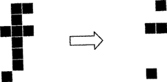
通过这些处理生成的影像像素数据,与只是把原像素表示为在1帧中抽出偶数排列的像素或者奇数排列的像素之一的像素群的图15A所示的数据进行比较,如图15B所示,因为表示像素间的变化高(大)的高值成分剩下,所以不会有大的像素劣化,能够确保某一程度的良好的视认性。The video pixel data generated by these processes is compared with the data shown in FIG. 15A in which the original pixels are simply expressed as pixel groups extracted from one of even-numbered pixels or odd-numbered pixels in one frame, as shown in FIG. 15B , since a high-value component indicating a high (large) variation between pixels remains, there is no large pixel degradation, and a certain degree of good visibility can be ensured.
这样,通过进行控制使得把至少包含1个进行了析像度变换的图像数据的多个图像数据排列替换为规定的显示方式进行显示,不设置新的构成,就可以以多个显示方式在1个显示部上显示多个图像数据。In this way, by performing control so that a plurality of image data including at least one resolution-converted image data is arranged and displayed in a predetermined display format, multiple display formats can be displayed in one display format without providing a new configuration. A plurality of image data are displayed on each display unit.
各种处理的顺序The order of various processes
以下,说明本实施例1的图像插补装置的各种处理的顺序。图16是表示图像插补处理的顺序的流程图。该图像插补处理在从AV单元320以及导航装置330受理了DVD影像的显示请求以及导航影像的显示请求时,如果涉及这些显示请求的显示方式的设定不是排他性设定而是2画面显示和2视野显示等的共存显示方式,则开始处理。The procedure of various processes performed by the image interpolation device of the first embodiment will be described below. FIG. 16 is a flowchart showing the procedure of image interpolation processing. In this image interpolation process, when a DVD video display request and a navigation video display request are received from the
如同一图所示,当从AV单元320以及导航装置330受理了DVD影像的显示请求以及导航影像的显示请求的情况下(步骤S601中肯定),图像数据输入部311按照DVD影像v1以及导航影像v2的每个输入系统,把这些图像数据输入到特征量计算部313(步骤S602)。As shown in the same figure, when a request to display a DVD video and a display request for a navigation video are received from the
而后,特征量计算部313以从图像数据输入部311输入的图像数据为基础,顺序计算位于插补对象区域的像素的特征量(步骤S603)。接着,图像插补处理部314在位于插补对象区域的像素中,抽出利用特征量计算部313计算出的特征量最大的像素(步骤S604)。Then, the feature
在此,当抽出的像素的特征量大于等于阈值的情况下(步骤S605中肯定),图像插补处理部314把该像素的像素值决定作为插补像素的像素值(步骤S606)。另一方面,当抽出的像素的特征量小于阈值的情况下(步骤S605中否定),把位于插补对象区域的各像素的像素值各自决定作为插补像素的像素值(步骤S607)。Here, when the feature value of the extracted pixel is greater than or equal to the threshold (Yes in step S605), the image
而后,当对全部的插补对象区域决定了插补像素的像素值的情况下(步骤S608中肯定),图像插补处理部314生成反映了各插补像素的像素值的图像数据(步骤S609)。而且,当对全部的插补对象区域未决定插补像素的像素值的情况下(步骤S608中否定),直到对全部的插补对象区域决定插补像素的像素值为止,循环地进行上述步骤S603~S607的处理。Then, when the pixel values of the interpolation pixels have been determined for all interpolation target regions (Yes in step S608), the image
接着,析像度变换处理部315对用图像插补处理部314进行了插补像素的插补的导航影像的图像数据和DVD影像的图像数据分别执行1/2水平析像度变换处理(步骤S610)。Next, the resolution
而后,显示控制处理部316把用析像度变换处理部315进行了1/2水平析像度变换处理的导航影像的图像数据以及DVD影像的图像数据排列替换为规定的显示方式进行显示(步骤S611)。Then, the display
最后,当导航影像或者DVD影像之一,或者导航影像以及DVD影像的双方结束的情况下(步骤S612中肯定),结束处理,当导航影像以及DVD影像的双方未结束的情况下(步骤S612中否定),重复上述步骤S602~S611为止的处理。Finally, when one of the navigation image or the DVD image, or both of the navigation image and the DVD image are finished (affirmatively in step S612), the process ends; Negative), repeat the above steps S602 to S611.
如上所示,如果采用本实施例1的图像插补装置310,因为,抽出位于插补对象区域的像素中特征量最大的像素,如果该抽出的像素的特征量大于等于阈值,则把该像素的像素值决定作为插补像素的像素值,所以,能够从插补对象区域中抽出在原图像中对图像赋予特征的概率高的像素,把该抽出的像素的像素值作为插补像素的像素值更优先地采用,可以更有效地抑制伴随图像数据的析像度变换的画质劣化。As mentioned above, if the image interpolation device 310 of the present embodiment 1 is used, the pixel with the largest feature value among the pixels located in the interpolation target area is extracted, and if the feature value of the extracted pixel is greater than or equal to the threshold value, the pixel is The pixel value of is determined as the pixel value of the interpolation pixel. Therefore, it is possible to extract a pixel with a high probability of characterizing the image in the original image from the interpolation target area, and use the pixel value of the extracted pixel as the pixel value of the interpolation pixel. Using it more preferentially can more effectively suppress image quality degradation accompanying the resolution conversion of image data.
实施例2Example 2
此前虽然说明了本发明的实施例,但本发明在上述的实施例1以外,也可以在上述专利申请的范围中记述的技术思想范围内用各种不同的实施例来实施。Heretofore, the embodiments of the present invention have been described, but the present invention can also be implemented in various embodiments within the scope of the technical idea described in the scope of the above-mentioned patent application other than the above-mentioned first embodiment.
例如,在实施例1中,说明了当受理了多个显示请求(即,DVD影像以及导航影像的显示请求)的情况下,进行本发明的图像插补处理的实施例,但本发明并不限于此,无论显示请求是一个还是多个都可以同样适用本发明。特别是本发明即使在显示请求是一个的情况下,对于有析像度变换的需求(例如,要求与手机等比较小的显示部一致的析像度变换的情况下)的图像数据,通过适用本发明的图像插补处理能够得到更高的效果。For example, in Embodiment 1, an embodiment in which the image interpolation processing of the present invention is performed when a plurality of display requests (that is, requests for display of DVD video and navigation video) are accepted, the present invention does not Limited to this, the present invention is equally applicable regardless of whether there are one display request or multiple display requests. In particular, even when there is only one display request, the present invention can be applied to image data that requires resolution conversion (for example, when a resolution conversion corresponding to a relatively small display unit such as a mobile phone is required). The image interpolation processing of the present invention can obtain higher effects.
此外,在实施例1中,说明了这样的实施例:在位于插补对象区域的像素中,抽出用特征量计算部313计算的特征量最大的像素,如果该抽出的像素的特征量小于阈值,则把位于插补对象区域的各像素的像素值各自决定作为插补像素的像素值,但本发明并不限于此,如果抽出的像素的特征量小于阈值,也可以把对位于插补对象区域的像素的像素值进行了平均化的像素值决定作为插补像素的像素值。In addition, in Embodiment 1, an embodiment was described in which, among the pixels located in the interpolation target area, the pixel having the largest feature value calculated by the feature
如果用图17的例子进行说明,则如插补对象区域B那样,当抽出的“像素4”的特征量小于阈值“THRESH”的情况下,把对位于插补对象区域B上的“像素3”以及“像素4”进行了平均的像素值“(P3+P4)/2”决定作为插补像素(即,插补对象区域B)的像素值。Using the example in Fig. 17, as in the interpolation target area B, when the feature value of the extracted "
这样,在位于插补对象区域的像素中,抽出用特征量计算部313计算的特征量最大的像素,如果该抽出的像素的特征量小于阈值,则通过对把位于插补对象区域的像素的像素值进行了平均化的像素值决定作为插补像素的像素值,在相邻的像素的亮度水平没有大的偏离的情况下能够进行总体性的图像插补处理,能够有效地抑制伴随图像数据的析像度变换的画质劣化。In this way, among the pixels located in the interpolation target area, the pixel with the largest feature value calculated by the feature
此外,在本发明中,也可以计算位于插补对象区域的像素间的像素值的差,如果位于插补对象区域的像素间的像素值的差的绝对值大于等于阈值,则把对位于该插补对象区域的像素的像素值进行了平均化的像素值决定作为插补像素的像素值。In addition, in the present invention, it is also possible to calculate the difference in pixel values between pixels located in the interpolation target area, and if the absolute value of the difference in pixel values between pixels in the interpolation target area is greater than or equal to a threshold value, then The averaged pixel values of the pixels in the interpolation target area are determined as the pixel values of the interpolation pixels.
例如,如果用图18的例子进行说明,则计算位于插补对象区域A上的像素“像素1”以及“像素2”之间的像素值的差(即,“P2-P1”),如果位于插补对象区域的像素间的像素值的差的绝对值(即,|P1-P2|)大于等于阈值“THRESH”,则把对位于该插补对象区域A上的像素“像素1”以及“像素2”的像素值进行了平均的像素值“(P2+P1)/2”决定作为插补像素的像素值。此外,对于插补对象区域B、插补对象区域C...插补对象区域N也同样地进行图像插补处理。For example, if the example in FIG. 18 is used to describe, the difference in pixel value between the pixels "Pixel 1" and "
这样计算位于插补对象区域的像素间的像素值的差,如果位于插补对象区域的像素间的像素值的差的绝对值大于等于阈值,则通过把对位于该插补对象区域的像素的像素值进行了平均化的像素值决定作为插补像素的像素值,能够对在局部产生的亮度水平的大差异进行平滑化,可以有效地抑制伴随图像数据的析像度变换的画质劣化。In this way, the difference in pixel values between pixels located in the interpolation target area is calculated, and if the absolute value of the difference in pixel values between pixels in the interpolation target area is greater than or equal to the threshold value, the The averaged pixel values determine the pixel values used as interpolation pixels, which can smooth locally large differences in brightness levels and effectively suppress image quality degradation associated with resolution conversion of image data.
而且,在实施例1中,说明了输入到图像插补装置310中的影像信号是复合信号(RGB形式)的例,但本发明并不限于此,即使是输入了YC形式等其他形式的影像信号的情况下也能够同样地使用本发明。Furthermore, in Embodiment 1, an example in which the video signal input to the image interpolation device 310 is a composite signal (RGB format) is described, but the present invention is not limited thereto. The present invention can be similarly used in the case of signals.
此外,在本实施例中说明的各处理中,能够手动地进行被说明为自动地进行的处理的全部或者一部分,或者,还可以用公知的方法自动地进行被说明为手动进行的处理的全部或者一部分。此外,对于包含在上述文章中和附图中表示的处理顺序、控制顺序、具体的名称、各种数据、参数等(例如,析像度、析像度变换率等)的信息,除了特殊记述的情况外能够任意地改变。In addition, in each processing described in this embodiment, all or part of the processing described as being performed automatically can be performed manually, or all of the processing described as being performed manually can be performed automatically by a known method. or part of it. In addition, information including processing procedures, control procedures, specific names, various data, parameters, etc. (for example, resolution, resolution conversion rate, etc.) shown in the above text and drawings, unless otherwise specified can be changed arbitrarily.
此外,图示的各装置的各构成要素是功能概念性的,不需要必须物理地如图示那样构成。即,各装置的分散/统合的具体的方式并不限于图示的例子,根据各种负荷、使用状况等能够把其全部或者一部分以任意的单位进行功能性或者物理性分散/统合而构成。进而,在各装置中进行的各处理功能其全部或者任意一部分可以用CPU以及在该CPU中分析执行的程序实现,或者,可以作为采用布线逻辑的硬件实现。In addition, each constituent element of each device shown in the figure is functional and conceptual, and does not necessarily have to be physically configured as shown in the figure. That is, the specific form of dispersing/integrating each device is not limited to the illustrated example, and all or part of them can be functionally or physically disperse/integrated in arbitrary units according to various loads, usage conditions, and the like. Furthermore, all or any part of each processing function performed in each device may be realized by a CPU and a program analyzed and executed by the CPU, or may be realized as hardware using wired logic.
此外,在本实施例中是以在单一显示器上显示2个画面的2画面显示方式,和向2个方向输出不同的2个影像的2视野显示方式为例进行说明,但也可以作为显示3个或者3个以上的多画面的多画面显示方式,和向3个或者3个以上的多个方向输出不同的影像的多方向显示方式实施。In addition, in this embodiment, a 2-screen display method in which 2 screens are displayed on a single display, and a 2-view display method in which 2 different images are output in 2 directions are described as examples, but it can also be used as a display method for displaying 3 screens. The multi-screen display mode of one or more than three multi-screens, and the multi-directional display mode of outputting different images to three or more multiple directions are implemented.
此外,在本实施例中以车载用的装置为例子进行说明,但本发明的利用并不限于此,例如还可以适用到家用等车载用途以外的显示装置。In addition, in the present embodiment, a vehicle-mounted device is described as an example, but the application of the present invention is not limited thereto, and for example, it can be applied to a display device other than a vehicle-mounted device such as a household.
如上所示,本发明的图像插补装置以及显示装置在图像的插补中有用,特别适合于维持了原有图像的特征的析像度变换。As described above, the image interpolation device and display device of the present invention are useful for image interpolation, and are particularly suitable for resolution conversion that maintains the characteristics of the original image.
Claims (4)
Applications Claiming Priority (3)
| Application Number | Priority Date | Filing Date | Title |
|---|---|---|---|
| JP2004316906 | 2004-10-29 | ||
| JP316906/2004 | 2004-10-29 | ||
| JP265690/2005 | 2005-09-13 |
Publications (2)
| Publication Number | Publication Date |
|---|---|
| CN101053012A CN101053012A (en) | 2007-10-10 |
| CN100498928C true CN100498928C (en) | 2009-06-10 |
Family
ID=38783537
Family Applications (1)
| Application Number | Title | Priority Date | Filing Date |
|---|---|---|---|
| CNB2005800374206A Expired - Fee Related CN100498928C (en) | 2004-10-29 | 2005-10-19 | Image interpolation device and display device |
Country Status (1)
| Country | Link |
|---|---|
| CN (1) | CN100498928C (en) |
Families Citing this family (3)
| Publication number | Priority date | Publication date | Assignee | Title |
|---|---|---|---|---|
| US20210191191A1 (en) * | 2019-12-18 | 2021-06-24 | Innolux Corporation | Electronic device |
| US12361557B2 (en) | 2020-12-21 | 2025-07-15 | Medtronic Navigation, Inc. | Systems and methods for monitoring one or more anatomical elements |
| WO2025020107A1 (en) * | 2023-07-26 | 2025-01-30 | 镭亚股份有限公司 | Time-division multiplexed display, time-division multiplexed display system and method |
Citations (5)
| Publication number | Priority date | Publication date | Assignee | Title |
|---|---|---|---|---|
| US5280546A (en) * | 1990-11-29 | 1994-01-18 | Kabushiki Kaisha Toshiba | Image processing apparatus for variably magnifying image and controlling image density |
| CN1205601A (en) * | 1997-07-10 | 1999-01-20 | 三星电子株式会社 | Interpolation method for binary image |
| JP2002135569A (en) * | 2000-10-20 | 2002-05-10 | Matsushita Electric Ind Co Ltd | Image processing device |
| JP2003137005A (en) * | 2001-10-30 | 2003-05-14 | Denso Corp | Display for vehicle |
| JP2004104368A (en) * | 2002-09-06 | 2004-04-02 | Sony Corp | Image data processing method, image data processing program, and stereoscopic image display device |
-
2005
- 2005-10-19 CN CNB2005800374206A patent/CN100498928C/en not_active Expired - Fee Related
Patent Citations (5)
| Publication number | Priority date | Publication date | Assignee | Title |
|---|---|---|---|---|
| US5280546A (en) * | 1990-11-29 | 1994-01-18 | Kabushiki Kaisha Toshiba | Image processing apparatus for variably magnifying image and controlling image density |
| CN1205601A (en) * | 1997-07-10 | 1999-01-20 | 三星电子株式会社 | Interpolation method for binary image |
| JP2002135569A (en) * | 2000-10-20 | 2002-05-10 | Matsushita Electric Ind Co Ltd | Image processing device |
| JP2003137005A (en) * | 2001-10-30 | 2003-05-14 | Denso Corp | Display for vehicle |
| JP2004104368A (en) * | 2002-09-06 | 2004-04-02 | Sony Corp | Image data processing method, image data processing program, and stereoscopic image display device |
Also Published As
| Publication number | Publication date |
|---|---|
| CN101053012A (en) | 2007-10-10 |
Similar Documents
| Publication | Publication Date | Title |
|---|---|---|
| JP4255032B2 (en) | Display device and display method | |
| KR100869673B1 (en) | Display control device and display device | |
| KR100896030B1 (en) | Display device for being mounted in a car | |
| JP2006195415A (en) | Display apparatus and display method | |
| KR100854646B1 (en) | Video signal processing method, video signal processing device, and display device | |
| JP2006154756A5 (en) | ||
| JP2006184859A (en) | Display controller and display device | |
| US20100110094A1 (en) | Display control device, display device, and display control method | |
| JP2006154759A (en) | Image interpolation device and display device | |
| CN100498924C (en) | Display controller and display device | |
| CN100498928C (en) | Image interpolation device and display device | |
| JP2006154754A (en) | Display controller and display device | |
| CN100508013C (en) | Display device, image quality adjustment method for display device, image quality adjustment device, and contrast adjustment device | |
| WO2007001071A1 (en) | Display device and display device mounting method | |
| JP2009204862A (en) | Video signal processing apparatus, display device, and video signal processing method | |
| JP2006301573A (en) | Display device and display method | |
| JP2006259761A (en) | Display device for vehicle and display method | |
| JP4023815B2 (en) | Display device | |
| JP2009069838A (en) | Display device and display method | |
| JP2007025617A (en) | Contrast adjustment device, contrast adjustment method and display device |
Legal Events
| Date | Code | Title | Description |
|---|---|---|---|
| C06 | Publication | ||
| PB01 | Publication | ||
| C10 | Entry into substantive examination | ||
| SE01 | Entry into force of request for substantive examination | ||
| C14 | Grant of patent or utility model | ||
| GR01 | Patent grant | ||
| C17 | Cessation of patent right | ||
| CF01 | Termination of patent right due to non-payment of annual fee |
Granted publication date: 20090610 Termination date: 20121019 |