CN100474709C - Electrical connector - Google Patents
Electrical connector Download PDFInfo
- Publication number
- CN100474709C CN100474709C CNB2004800215385A CN200480021538A CN100474709C CN 100474709 C CN100474709 C CN 100474709C CN B2004800215385 A CNB2004800215385 A CN B2004800215385A CN 200480021538 A CN200480021538 A CN 200480021538A CN 100474709 C CN100474709 C CN 100474709C
- Authority
- CN
- China
- Prior art keywords
- group
- electric connector
- signal
- socket
- electrically
- Prior art date
- Legal status (The legal status is an assumption and is not a legal conclusion. Google has not performed a legal analysis and makes no representation as to the accuracy of the status listed.)
- Expired - Fee Related
Links
Images


Classifications
-
- H—ELECTRICITY
- H01—ELECTRIC ELEMENTS
- H01R—ELECTRICALLY-CONDUCTIVE CONNECTIONS; STRUCTURAL ASSOCIATIONS OF A PLURALITY OF MUTUALLY-INSULATED ELECTRICAL CONNECTING ELEMENTS; COUPLING DEVICES; CURRENT COLLECTORS
- H01R27/00—Coupling parts adapted for co-operation with two or more dissimilar counterparts
-
- H—ELECTRICITY
- H01—ELECTRIC ELEMENTS
- H01R—ELECTRICALLY-CONDUCTIVE CONNECTIONS; STRUCTURAL ASSOCIATIONS OF A PLURALITY OF MUTUALLY-INSULATED ELECTRICAL CONNECTING ELEMENTS; COUPLING DEVICES; CURRENT COLLECTORS
- H01R12/00—Structural associations of a plurality of mutually-insulated electrical connecting elements, specially adapted for printed circuits, e.g. printed circuit boards [PCB], flat or ribbon cables, or like generally planar structures, e.g. terminal strips, terminal blocks; Coupling devices specially adapted for printed circuits, flat or ribbon cables, or like generally planar structures; Terminals specially adapted for contact with, or insertion into, printed circuits, flat or ribbon cables, or like generally planar structures
- H01R12/70—Coupling devices
- H01R12/71—Coupling devices for rigid printing circuits or like structures
- H01R12/72—Coupling devices for rigid printing circuits or like structures coupling with the edge of the rigid printed circuits or like structures
- H01R12/721—Coupling devices for rigid printing circuits or like structures coupling with the edge of the rigid printed circuits or like structures cooperating directly with the edge of the rigid printed circuits
-
- H—ELECTRICITY
- H01—ELECTRIC ELEMENTS
- H01R—ELECTRICALLY-CONDUCTIVE CONNECTIONS; STRUCTURAL ASSOCIATIONS OF A PLURALITY OF MUTUALLY-INSULATED ELECTRICAL CONNECTING ELEMENTS; COUPLING DEVICES; CURRENT COLLECTORS
- H01R13/00—Details of coupling devices of the kinds covered by groups H01R12/70 or H01R24/00 - H01R33/00
- H01R13/62—Means for facilitating engagement or disengagement of coupling parts or for holding them in engagement
- H01R13/629—Additional means for facilitating engagement or disengagement of coupling parts, e.g. aligning or guiding means, levers, gas pressure electrical locking indicators, manufacturing tolerances
- H01R13/631—Additional means for facilitating engagement or disengagement of coupling parts, e.g. aligning or guiding means, levers, gas pressure electrical locking indicators, manufacturing tolerances for engagement only
- H01R13/6315—Additional means for facilitating engagement or disengagement of coupling parts, e.g. aligning or guiding means, levers, gas pressure electrical locking indicators, manufacturing tolerances for engagement only allowing relative movement between coupling parts, e.g. floating connection
-
- H—ELECTRICITY
- H01—ELECTRIC ELEMENTS
- H01R—ELECTRICALLY-CONDUCTIVE CONNECTIONS; STRUCTURAL ASSOCIATIONS OF A PLURALITY OF MUTUALLY-INSULATED ELECTRICAL CONNECTING ELEMENTS; COUPLING DEVICES; CURRENT COLLECTORS
- H01R24/00—Two-part coupling devices, or either of their cooperating parts, characterised by their overall structure
- H01R24/60—Contacts spaced along planar side wall transverse to longitudinal axis of engagement
- H01R24/62—Sliding engagements with one side only, e.g. modular jack coupling devices
-
- H—ELECTRICITY
- H01—ELECTRIC ELEMENTS
- H01R—ELECTRICALLY-CONDUCTIVE CONNECTIONS; STRUCTURAL ASSOCIATIONS OF A PLURALITY OF MUTUALLY-INSULATED ELECTRICAL CONNECTING ELEMENTS; COUPLING DEVICES; CURRENT COLLECTORS
- H01R33/00—Coupling devices specially adapted for supporting apparatus and having one part acting as a holder providing support and electrical connection via a counterpart which is structurally associated with the apparatus, e.g. lamp holders; Separate parts thereof
-
- H—ELECTRICITY
- H05—ELECTRIC TECHNIQUES NOT OTHERWISE PROVIDED FOR
- H05K—PRINTED CIRCUITS; CASINGS OR CONSTRUCTIONAL DETAILS OF ELECTRIC APPARATUS; MANUFACTURE OF ASSEMBLAGES OF ELECTRICAL COMPONENTS
- H05K1/00—Printed circuits
- H05K1/02—Details
- H05K1/11—Printed elements for providing electric connections to or between printed circuits
- H05K1/117—Pads along the edge of rigid circuit boards, e.g. for pluggable connectors
-
- H—ELECTRICITY
- H01—ELECTRIC ELEMENTS
- H01R—ELECTRICALLY-CONDUCTIVE CONNECTIONS; STRUCTURAL ASSOCIATIONS OF A PLURALITY OF MUTUALLY-INSULATED ELECTRICAL CONNECTING ELEMENTS; COUPLING DEVICES; CURRENT COLLECTORS
- H01R2107/00—Four or more poles
-
- H—ELECTRICITY
- H05—ELECTRIC TECHNIQUES NOT OTHERWISE PROVIDED FOR
- H05K—PRINTED CIRCUITS; CASINGS OR CONSTRUCTIONAL DETAILS OF ELECTRIC APPARATUS; MANUFACTURE OF ASSEMBLAGES OF ELECTRICAL COMPONENTS
- H05K2201/00—Indexing scheme relating to printed circuits covered by H05K1/00
- H05K2201/09—Shape and layout
- H05K2201/09145—Edge details
-
- H—ELECTRICITY
- H05—ELECTRIC TECHNIQUES NOT OTHERWISE PROVIDED FOR
- H05K—PRINTED CIRCUITS; CASINGS OR CONSTRUCTIONAL DETAILS OF ELECTRIC APPARATUS; MANUFACTURE OF ASSEMBLAGES OF ELECTRICAL COMPONENTS
- H05K2203/00—Indexing scheme relating to apparatus or processes for manufacturing printed circuits covered by H05K3/00
- H05K2203/15—Position of the PCB during processing
- H05K2203/1572—Processing both sides of a PCB by the same process; Providing a similar arrangement of components on both sides; Making interlayer connections from two sides
-
- H—ELECTRICITY
- H05—ELECTRIC TECHNIQUES NOT OTHERWISE PROVIDED FOR
- H05K—PRINTED CIRCUITS; CASINGS OR CONSTRUCTIONAL DETAILS OF ELECTRIC APPARATUS; MANUFACTURE OF ASSEMBLAGES OF ELECTRICAL COMPONENTS
- H05K2203/00—Indexing scheme relating to apparatus or processes for manufacturing printed circuits covered by H05K3/00
- H05K2203/16—Inspection; Monitoring; Aligning
- H05K2203/168—Wrong mounting prevention
Landscapes
- Engineering & Computer Science (AREA)
- Microelectronics & Electronic Packaging (AREA)
- Details Of Connecting Devices For Male And Female Coupling (AREA)
- Coupling Device And Connection With Printed Circuit (AREA)
- Connector Housings Or Holding Contact Members (AREA)
Abstract
本发明揭示一种电连接器(30),例如一将与通用串行总线一起操作的连接器。在有些实施例中,所述连接器(30)包括0个、1个或若干舌片板(301)、舌片尖端、电接触体(302)、罩壳、罩壳内衬上的绝缘片和保护边缘(303)。本发明也揭示一种集成到一印刷电路板中的连接器。本发明揭示其它实施例。
This invention discloses an electrical connector (30), such as a connector for operation with a Universal Serial Bus (USB). In some embodiments, the connector (30) includes one, one, or several tongue plates (301), tongue tips, electrical contacts (302), a housing, an insulating sheet on the housing liner, and a protective edge (303). This invention also discloses a connector integrated into a printed circuit board. Other embodiments are disclosed.
Description
技术领域 technical field
本发明涉及一种电连接器,并且尤其涉及一种通用串行总线(USB)连接器。The present invention relates to an electrical connector, and more particularly to a Universal Serial Bus (USB) connector.
背景技术 Background technique
在许多情况下,使用有线连接将计算机连接到外围设备或电子设备上。一种有线连接为通用串行总线(以下称为USB)电缆。可使用USB电缆电连接计算机与外围设备和其它电子设备。计算机外围设备的实例为例如鼠标和键盘的输入器件、例如打印机的输出器件和例如外部硬驱动器和闪存驱动器的输入/输出器件。电子设备的实例有数码照相机、PDA和MP3播放机。In many cases, a wired connection is used to connect a computer to a peripheral or electronic device. One wired connection is a Universal Serial Bus (hereinafter USB) cable. Computers can be electrically connected to peripherals and other electronic devices using USB cables. Examples of computer peripherals are input devices such as mice and keyboards, output devices such as printers, and input/output devices such as external hard drives and flash drives. Examples of electronic devices are digital cameras, PDAs and MP3 players.
20世纪90年代后期,USB标准在计算机行业中成了优选连接接口,并且在如今制造的几乎所有计算机中变得普及。为了利用USB结构周围建立的多种外围设备和电子设备,膝上型计算机、桌上型计算机和其它计算机器都制造有USB端口。(参看www.USB.org)In the late 1990s, the USB standard became the preferred connection interface in the computer industry, and it is ubiquitous in almost all computers manufactured today. In order to take advantage of the variety of peripherals and electronic devices built around the USB architecture, laptops, desktops, and other computing machines are manufactured with USB ports. (See www.USB.org)
通用串行总线和USB连接器在此项技术中是众所周知的。USB标准和USB连接器的普及对于消费者来说效用得以提高、和其它接口方法相比数据传输速度大为提高,并且由于标准化而对于外围器件制造商来说降低了成本。计算机销售商通常将一个或一个以上USB端口集成到其输入输出端口组中。Universal Serial Bus and USB connectors are well known in the art. The proliferation of the USB standard and USB connectors has resulted in increased utility for consumers, greatly increased data transfer speeds compared to other interface methods, and reduced costs for peripheral device manufacturers due to standardization. Computer vendors typically integrate one or more USB ports into their input and output port sets.
用来将外围设备或电子设备连接到计算机上的USB电缆是由2个称作连接器或插头的端点组成。一个连接器(称作串行“A”插头)连接到主机,而另一个连接器(称作串行“B”插头)连接到连接设备。串行“A”和“B”插头具有不同形状和尺寸,以免将二者混淆。主机上的接口连接被称为USB装配端口(以下称为USB端口)。USB端口由一个与串行“A”插头配对的串行“A”插座组成。串行“A”电气地充当主系统的输出。图1展示一个现有技术的串行“A”插头10,此插头与串行“A”插座12配对。串行“A”插头始终朝向主系统。在2003年7月28日提交的序列号为60/480,413的临时申请案(标题为“Electrical Connector”,以下称为“临时申请案”)中展示了插头和连接器的照片,其以引用的方式并入本文中。A USB cable used to connect a peripheral or electronic device to a computer consists of two ends called connectors or plugs. One connector (called the serial "A" plug) connects to the host computer, while the other connector (called the serial "B" plug) connects to the attached device. Serial "A" and "B" plugs are different shapes and sizes so as not to confuse the two. The interface connection on the host is called a USB mounting port (hereinafter referred to as a USB port). The USB port consists of a serial "A" receptacle mated to a serial "A" plug. Serial "A" electrically acts as the output of the main system. FIG. 1 shows a prior art serial "A"
计算机主机USB端口是一个具有平坦的内矩形卡的敞开插座,所述卡上带有电接触点。连接到主机插座的电缆串行“A”插头以一个插入主机插座的矩形套(sleeve)终止。所述套中含有一个舌片板,其带有与主机插座的电接触点相匹配的电接触点。将套插入插座中就使得卡和舌片依附在一起从而产生配对电连接。A computer host USB port is an open socket with a flat inner rectangular card with electrical contacts on it. The cable serial "A" plug that connects to the host socket is terminated with a rectangular sleeve that fits into the host socket. The sleeve contains a tongue plate with electrical contacts that match the electrical contacts of the host socket. Inserting the sleeve into the receptacle causes the card and tongue to adhere together creating a mating electrical connection.
有些外围器件不是使用USB电缆来连接到计算机,而是把USB连接器用作其组件的一部分。实例有钥匙串(keychain)存储器件(参看www.diskonkey.com,www.thumbdrive.com)或安全钥匙(security key,参看www.ealaddin.com)。所述临时申请案展示一插入主机PC(个人计算机)USB端口的USB驱动器。钥匙串存储器件由于尺寸较小而用作便携式存储媒体,并且因此经常与若干计算机一起使用。因此,这些器件会多次插入或拔出主机。Instead of using a USB cable to connect to the computer, some peripherals use the USB connector as part of their assembly. Examples are keychain storage devices (see www.diskonkey.com, www.thumbdrive.com) or security keys (see www.ealaddin.com). The provisional application shows a USB drive plugged into a host PC (Personal Computer) USB port. Keychain storage devices are used as portable storage media due to their small size, and are therefore often used with several computers. Therefore, these devices are plugged and unplugged from the host many times.
遗憾的是,USB连接器的结构设计中存在缺陷,当将USB连接器插入到USB端口中时这一缺陷就会显示出来。再次参看图1,可以看出,尽管从外部触摸和观测来看插座12和插头10似乎是对称的,但是二者在内部并不对称。在主机插座中,这是因为位于插座内的矩形卡101和电连接器102的定位所致。图2a到图2c展示USB主机插座100的一实例。图2描述现有技术的USB插座的三个视图。特定地说,图2a展示一前截面,图2b展示一侧视图截面,而图2c展示一底侧视图截面。参看这些图,矩形卡101定位在插座100中。电接触点102形成在卡101上。Unfortunately, there is a flaw in the structural design of the USB connector that manifests itself when the USB connector is inserted into a USB port. Referring again to FIG. 1 , it can be seen that although the
图3a到图3c描述现有技术的串行“A”USB插头的实例。特定地说,图3a描述一顶视图截面,图3b描述一前视图截面,而图3c描述一侧视图截面。现有技术的插头连接器包括一外壳200。舌片板201定位在外壳中,电接触点202形成在舌片板上。同样,在USB连接器外壳200中,舌片201和电接触202以非对称的方式定位。Figures 3a to 3c depict examples of prior art serial "A" USB plugs. In particular, Figure 3a depicts a top view section, Figure 3b depicts a front view section, and Figure 3c depicts a side view section. The prior art plug connector includes a
在许多情况下,在主机USB端口所定位的角度上,用户不能轻松地看见插座内部,所以用户不清楚如何对准插头才能正确地插入和电配对。图4和图5描述如何配对现有技术的USB插头和USB插座。只有当插座的内矩形卡101和USB插头的内舌片板201如图4所示正确地彼此相对时,USB插头的矩形套才能正确装配到USB端口的矩形插座100中。图5说明当插头正确插入插座时的情形。当不是此情形时,由于插座的内矩形卡101与USB连接器的内舌片板201像(同为现有技术的)图6a和图6b中所示的一样碰撞,所以不可能实现电配对。图6a展示一类似于图5的视图,只是插座100和外壳200没有正确对准。图6b展示由于此未对准而导致的碰撞205。In many cases, at the angle at which the host USB port is positioned, the user cannot easily see inside the receptacle, so it is not clear to the user how to align the plug for proper insertion and electrical mating. Figures 4 and 5 describe how to mate a prior art USB plug and USB receptacle. Only when the inner
在有些情况下,用户可能不会看到主机USB插座中的内部对准,因为它位于计算机的后面或侧面。据统计,由于当矩形插头连接到矩形插座时似乎有两种对准可能性,但是仅有一种可能性是正确对准,所以未成功插入的几率为50%。此导致USB器件使用中用户体验的降级。由于更多的设备使用USB连接器连接到计算机,这个问题增强了。对于多次插入和拔出许多计算机的钥匙串存储器件来说,这种不便会增加。In some cases, the user may not see the internal alignment in the host USB receptacle because it is on the back or side of the computer. Statistically, since there appear to be two alignment possibilities when a rectangular plug is connected to a rectangular receptacle, but only one possibility is correct alignment, the chance of unsuccessful insertion is 50%. This results in a degradation of the user experience in the use of the USB device. This problem has intensified as more devices are connected to computers using USB connectors. This inconvenience is compounded by the multiple plugging and unplugging of keychain storage devices into many computers.
显然,存在一种尚未满足的需要,即需要一种可与USB一起操作的插头机构,其允许插头正确插入USB端口而无需用户考虑插头对准。Clearly, there is an unmet need for a plug mechanism operable with USB that allows the plug to be properly inserted into the USB port without the user having to worry about plug alignment.
发明内容 Contents of the invention
一方面,本发明提供一种解决上述问题的方法并且描述USB插头的改进。在一示范性实施例中(以下称为SLIM实施例),连接器舌片板没有定位在外壳中。所述舌片板有两组接触点,其每一侧上各有一组接触点,所述舌片板可以两种对准正确插入主机插座中。由于这些接触点位于舌片板的两侧,所以任何对准都将提供正确电配对。In one aspect, the present invention provides a solution to the above-mentioned problems and describes improvements in USB plugs. In an exemplary embodiment (hereinafter referred to as the SLIM embodiment), the connector tongue plate is not positioned in the housing. The tongue plate has two sets of contact points, one set of contact points on each side, and the tongue plate can be correctly inserted into the host socket in two alignments. Since these contact points are on both sides of the tongue plate, any alignment will provide the correct electrical pairing.
在本发明的另一示范性实施例中(以下称为FLEX实施例),通过以下方式来获得解决方法:使用一个能根据计算机插座的矩形卡位置而自身定位的柔性舌片板,从而在每次插入时实现电配对。此处也存在两组接触点,各位于柔性舌片板的每一侧。In another exemplary embodiment of the present invention (hereinafter referred to as the FLEX embodiment), the solution is obtained by using a flexible tongue plate that positions itself according to the rectangular card position of the computer socket, so that at each Electrical pairing is achieved upon first insertion. There are also two sets of contact points here, one on each side of the flexible tongue plate.
为了降低制造和组装费用,又展现了另一示范性实施例,其中可与USB插座一起操作的新颖连接器为外围器件的印刷电路板(PCB)中的一部分。To reduce manufacturing and assembly costs, yet another exemplary embodiment is presented wherein a novel connector operable with a USB receptacle is part of a peripheral device's printed circuit board (PCB).
为了可以更好地理解接下来对本发明的详细描述,上述内容已相当广泛地概括了本发明的实施例的特征和技术优点。下文中将描述本发明的实施例的其它特征和优点,这些特征和优点形成本发明的权利要求的主题。所属领域的技术人员应了解,可容易地以所揭示的概念和特定实施例为根据来更改或设计其它结构或步骤,以便实现本发明的相同目的。所属领域的技术人员也应了解,这种等效结构并不偏离如附加权利要求中所界定的本发明的精神和范畴,而且这种等效结构属于附加权利要求的范畴内。In order that the ensuing detailed description of the invention may be better understood, the foregoing has outlined rather broadly the features and technical advantages of embodiments of the invention. Additional features and advantages of embodiments of the invention will be described hereinafter which form the subject of the claims of the invention. It should be appreciated by those skilled in the art that the disclosed conception and specific embodiments may be used as the basis to modify or design other structures or steps, so as to achieve the same purpose of the present invention. It should also be realized by those skilled in the art that such equivalent constructions do not depart from the spirit and scope of the invention as defined in the appended claims and that such equivalent constructions are within the scope of the appended claims.
附图说明 Description of drawings
为了更完整地理解本发明和其优点,现参照结合附图所进行的下列描述,其中:For a more complete understanding of the invention and its advantages, reference is now made to the following description taken in conjunction with the accompanying drawings, in which:
图1描述现有技术的USB电缆上的一个串行“A”USB插头和一个串行“A”USB插座;Figure 1 depicts a serial "A" USB plug and a serial "A" USB receptacle on a prior art USB cable;
图2a到图2c描述现有技术USB插座的多个视图;Figures 2a to 2c depict various views of a prior art USB receptacle;
图3a到图3c描述现有技术USB插头的多个视图;Figures 3a to 3c depict various views of a prior art USB plug;
图4描述一个插入主机USB插座的现有技术USB插头的正确对准;Figure 4 depicts the correct alignment of a prior art USB plug inserted into a host USB receptacle;
图5描述以正确对准而配对的现有技术的正确插入USB插头和USB插座的组合;Figure 5 depicts a prior art combination of properly inserted USB plug and USB receptacle mated in proper alignment;
图6a到图6b说明现有技术USB插头插入主机USB插座的不正确尝试;Figures 6a-6b illustrate incorrect attempts to insert a prior art USB plug into a host USB receptacle;
图7为本发明的示范性SLIM实施例的示意图(在4个视图中:视图7a到视图7d);Figure 7 is a schematic diagram of an exemplary SLIM embodiment of the present invention (in 4 views: view 7a to view 7d);
图8为本发明的示范性SLIM实施例侧视的示意图,其包括本发明的本实施例的电接触点的布局;8 is a schematic diagram of a side view of an exemplary SLIM embodiment of the present invention, including the layout of the electrical contacts of this embodiment of the present invention;
图9a到图9b说明本发明的示范性SLIM实施例向主机USB端口的插入;Figures 9a-9b illustrate the insertion of an exemplary SLIM embodiment of the present invention into a host USB port;
图10为本发明的示范性FLEX实施例的示意图(在3个视图中:视图10a到视图10c);Figure 10 is a schematic diagram of an exemplary FLEX embodiment of the present invention (in 3 views: view 10a to view 10c);
图11为本发明的示范性FLEX实施例侧视的示意图,其包括本发明的本实施例的电接触点的布局;Figure 11 is a schematic diagram of a side view of an exemplary FLEX embodiment of the present invention, including the layout of the electrical contacts of this embodiment of the present invention;
图12a到图12c说明本发明的示范性FLEX实施例向主机USB端口的插入;Figures 12a to 12c illustrate the insertion of an exemplary FLEX embodiment of the present invention into a host USB port;
图13a到图13c为本发明的FLEX实施例向主机USB端口的插入的另一个说明;和Figures 13a to 13c are another illustration of the insertion of a FLEX embodiment of the present invention into a host USB port; and
图14a到图14b为本发明的另一实施例的示意图,其中本发明的USB连接器为外围器件PCB的一个组成部分。14a to 14b are schematic diagrams of another embodiment of the present invention, wherein the USB connector of the present invention is an integral part of the peripheral device PCB.
不同附图中的对应数字和符号通常指示对应零件,除非另有说明。绘制附图是为了清楚地说明优选实施例的有关方面并且未必是按比例绘制。Corresponding numerals and symbols in the different figures generally indicate corresponding parts unless otherwise indicated. The drawings are drawn to clearly illustrate aspects of the preferred embodiments and are not necessarily drawn to scale.
具体实施方式 Detailed ways
下文将更详细地论述当前优选实施例的制造和使用。然而,应了解,本发明提供可包含在多种特定上下文中的许多可适用发明概念。所论述的特定实施例只是说明制造和使用本发明的特殊方法,并且不限制本发明的范畴。The making and using of the presently preferred embodiments are discussed in greater detail below. It should be appreciated, however, that the present invention provides many applicable inventive concepts that can be embodied in a wide variety of specific contexts. The specific embodiments discussed are merely illustrative of specific ways to make and use the invention, and do not limit the scope of the invention.
在本发明示范性实施例的下列详细描述中,参照说明特定示范性实施例的附图,在这些实施例中可实践本发明。所属领域的技术人员应了解,在不偏离本发明精神的情况下可使用其它实施例;因此,不应以限制意义来理解以下对本发明的详细描述。In the following detailed description of exemplary embodiments of the invention, reference is made to the accompanying drawings that illustrate specific exemplary embodiments in which the invention may be practiced. Those skilled in the art will appreciate that other embodiments can be utilized without departing from the spirit of the invention; therefore, the following detailed description of the invention should not be taken in a limiting sense.
本发明的优选实施例是现有USB串行“A”插头的一种改进。这一改进是通过以下方式实现的:在连接器舌片板的两侧上提供电接触点,从而使可与USB一起操作的器件的改良插头连接器容易插入USB主机中。The preferred embodiment of the present invention is an improvement over the existing USB serial "A" plug. This improvement is achieved by providing electrical contact points on both sides of the connector tongue plate, thereby facilitating insertion of a modified plug connector of a device operable with USB into a USB host.
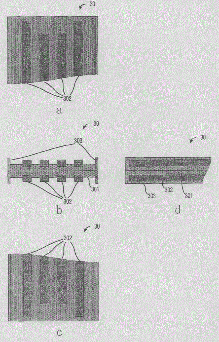
图7(其包括顶视图图7a、正视图图7b、仰视图图7c和顶部侧视图7d)描述根据本发明的一个实施例(SLIM实施例)的电插头30。所述插头30包括一舌片301、位于舌片301两侧的多个接触体(contact)302和保护边缘303。舌片301可以为USB电缆的端点,或例如钥匙串存储器件的外围器件的组成部分。Fig. 7 (which includes top view Fig. 7a, front view Fig. 7b, bottom view Fig. 7c and top side view 7d) depicts an
图9a和图9b描述将插头30连接到USB插座100的尝试。插头30的实体结构关于横轴对称。当舌片301与USB插座100相遇时,舌片301占据插座100中的可用空余空间,从而产生电连接。9a and 9b depict an attempt to connect the
电接触体302位于舌片301的两侧。此确保以两种可能对准中的任一种将舌片301插入插座100中都将产生正确的电配对。为了确保无论舌片301的最初对准如何,电接触点302中的每个电接触点都与USB端口1中的正确电接触点102配对,如图8所示将位于舌片301每一侧的电接触点对向地对准。The
图8中,电接触点302被各自标以数字1、2、3或4。在优选实施例中,接触点载送如表1所界定的电信号。In FIG. 8 , the
表1Table 1
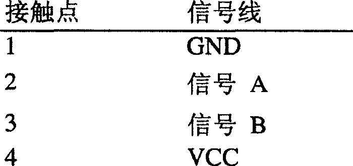
在有些实例中,USB插座100可用作共用电气接地。为了防止位于舌片301相对侧而没有参与电配对的电接触点302短路,使用保护边缘303。保护边缘303从舌片301突出,比电接触体302稍更突出,因此其防止实体连接到罩壳100,否则可能会引起短路。In some instances,
图10a(顶视图)、图10b(正视图)和图10c(侧视图)展示一个根据本发明另一实施例(FLEX实施例)的电插头40。所述插头40包括一外壳400、一柔性舌片401、一舌片尖端402、位于柔性舌片401两侧上的多个接触体403和绝缘片404。所述401位于外壳400内部、外壳400的横轴的中心位置上。Figure 10a (top view), Figure 10b (front view) and Figure 10c (side view) show an
图12a到图12c描述将插头40连接到USB插座100的尝试。图12a展示配对前的插头40。图12b展示柔性舌片401与矩形卡101相遇时的对准。图12c展示配对之后的插头。图13a到图13c为说明相同操作的类似视图,除了舌片401沿相反方向弯曲以外。由于舌片板定位于外壳400的中间,所以插头40的结构关于横轴对称。当外壳400与插座100相遇时,舌片尖端402面对矩形卡101并且协助柔性舌片401转向并且防止矩形卡101与柔性舌片401碰撞。随着外壳400继续朝插座100中插入,柔性舌片401占据插座100内的可用空余空间并且产生电连接。12a to 12c depict an attempt to connect the
电接触体403位于柔性舌片301两侧,以便无论柔性舌片不得不如图12所示朝下移动或如图13所示朝上移动,都能既确保插头40插入USB插座100又确保正确的电配对。The
在有些USB连接器中,外壳400可用作共用电气接地。为了防止未参与电配对的电接触点403短路,将绝缘片404在外壳400中直线排列。In some USB connectors,
为了确保无论柔性舌片401的最初对准如何,每个电接触点402都能与USB端口1中的正确电接触点102配对,如图11所示将柔性舌片301每一侧上的电接触点对向地对准。表1中展示了与接触点对应的信号/电源电压。To ensure that each
图14a和图14b展示—SLIM实施例的实例,其中在没有使用电缆的情况下用本发明将外围器件50连接到USB主机(未图示)。电插头30为印刷电路板(PCB)500的一个组成部分。通过使用内电接触体502将内电子线路501连接到顶部电接触点302。在顶视图图14a中,顶部内电接触体502直接连接到顶部电接触点302。在仰视图图14b中,电插头30必须保持相同次序并且相对于顶部电接触体302定位底部电接触点304。然而,内电子线路501顶部和底部都为相同芯片(例如,硅件)。因此,底部内电接触体504必须交叉以便与底部电接触点304匹配。通过减少组装外围器件50所需的零件的数目,可获得较低的制造费用。Figures 14a and 14b show an example of a SLIM embodiment where the present invention is used to connect a
尽管已详细地描述了本发明的实施例和其优点,但是应了解,在不偏离如附加权利要求所界定的本发明精神和范畴的情况下可对本发明进行多种改变、代替和变更。例如,所属领域的技术人员将容易了解,本文所描述的许多特征、功能、程序和材料可以变化而同时仍然保留在本发明的范畴内。此外,我们不希望将本申请案的范畴限于本说明书中所描述的程序、机器、制造、物质的成分、装置、方法和步骤的特定实施例。所属领域的技术人员从本发明的揭示内容中将容易明白,根据本发明可使用实现与本文所描述的对应实施例大体上相同的功能或获得与其大体上相同的结果的程序、机器、制造、物质的成份、装置、方法和步骤(当前存在的或以后将研发的)。因此,希望附加权利要求的范畴中包含这些程序、机器、制造、物质的成分、装置、方法或步骤。Although the embodiments of the present invention and its advantages have been described in detail, it should be understood that various changes, substitutions and alterations can be made herein without departing from the spirit and scope of the invention as defined by the appended claims. For example, it will be readily apparent to those skilled in the art that many of the features, functions, procedures, and materials described herein may be varied while remaining within the scope of the invention. Furthermore, we do not intend to limit the scope of the application to the particular embodiments of the procedure, machine, manufacture, composition of matter, means, methods and steps described in the specification. It will be readily apparent to those skilled in the art from this disclosure that a program, machine, manufacture, process, or process that performs substantially the same function or obtains substantially the same results as the corresponding embodiment described herein may be used in accordance with the present invention. Compositions of matter, devices, methods and procedures (currently existing or to be developed in the future). Accordingly, it is intended that such processes, machines, manufacture, compositions of matter, means, methods, or steps be within the scope of the appended claims.
Claims (35)
Applications Claiming Priority (2)
| Application Number | Priority Date | Filing Date | Title |
|---|---|---|---|
| US49041303P | 2003-07-28 | 2003-07-28 | |
| US60/490,413 | 2003-07-28 |
Publications (2)
| Publication Number | Publication Date |
|---|---|
| CN1830122A CN1830122A (en) | 2006-09-06 |
| CN100474709C true CN100474709C (en) | 2009-04-01 |
Family
ID=34115392
Family Applications (1)
| Application Number | Title | Priority Date | Filing Date |
|---|---|---|---|
| CNB2004800215385A Expired - Fee Related CN100474709C (en) | 2003-07-28 | 2004-07-26 | Electrical connector |
Country Status (8)
| Country | Link |
|---|---|
| US (3) | US7361059B2 (en) |
| EP (1) | EP1649555B1 (en) |
| JP (1) | JP4898437B2 (en) |
| KR (1) | KR101193977B1 (en) |
| CN (1) | CN100474709C (en) |
| AT (1) | ATE498219T1 (en) |
| DE (1) | DE602004031343D1 (en) |
| WO (1) | WO2005013436A1 (en) |
Cited By (3)
| Publication number | Priority date | Publication date | Assignee | Title |
|---|---|---|---|---|
| CN103140995A (en) * | 2010-05-28 | 2013-06-05 | 苹果公司 | Dual-directional connector with external contacts |
| CN104538773A (en) * | 2014-12-19 | 2015-04-22 | 刘红梅 | Reversible power plug connector |
| WO2016115692A1 (en) * | 2015-01-21 | 2016-07-28 | 刘红梅 | Power plug connector capable of being plugged reversibly |
Families Citing this family (86)
| Publication number | Priority date | Publication date | Assignee | Title |
|---|---|---|---|---|
| US8073985B1 (en) | 2004-02-12 | 2011-12-06 | Super Talent Electronics, Inc. | Backward compatible extended USB plug and receptacle with dual personality |
| US7440287B1 (en) * | 2000-01-06 | 2008-10-21 | Super Talent Electronics, Inc. | Extended USB PCBA and device with dual personality |
| EP1609048A4 (en) * | 2003-03-27 | 2009-01-14 | Milsys Ltd | Data storage device with full access by all users |
| US20050044330A1 (en) * | 2003-07-28 | 2005-02-24 | Gidon Elazar | System, apparatus and method for controlling a storage device |
| CN100474709C (en) * | 2003-07-28 | 2009-04-01 | 桑迪士克防护内容解决公司 | Electrical connector |
| TWI281117B (en) * | 2003-11-12 | 2007-05-11 | C One Technology Corp Ltd | Detachable interface I/O card device |
| US7771215B1 (en) | 2003-12-02 | 2010-08-10 | Super Talent Electronics, Inc. | MLC COB USB flash memory device with sliding plug connector |
| US8021166B1 (en) | 2004-02-12 | 2011-09-20 | Super Talent Electronics, Inc. | Extended USB plug, USB PCBA, and USB flash drive with dual-personality for embedded application with mother boards |
| US7815469B1 (en) | 2004-02-12 | 2010-10-19 | Super Talent Electronics, Inc. | Dual-personality extended USB plugs and receptacles using with PCBA and cable assembly |
| US7869219B2 (en) * | 2004-01-20 | 2011-01-11 | Super Talent Electronics, Inc. | Flash drive with spring-loaded retractable connector |
| US7487265B2 (en) * | 2004-04-16 | 2009-02-03 | Sandisk Corporation | Memory card with two standard sets of contacts and a hinged contact covering mechanism |
| JP2008508694A (en) | 2004-08-02 | 2008-03-21 | サンディスク アイエル リミテッド | Reversible universal serial bus (USB) devices and connectors |
| US6981887B1 (en) * | 2004-08-26 | 2006-01-03 | Lenovo (Singapore) Pte. Ltd. | Universal fit USB connector |
| TWI288315B (en) * | 2004-11-01 | 2007-10-11 | Innodisk Corp | Universal serial bus applied device |
| US7381076B2 (en) * | 2005-01-10 | 2008-06-03 | Sandisk Il Ltd. | Thin peripheral for mating with thicker connector |
| JP3111031U (en) * | 2005-04-04 | 2005-07-07 | 安國國際科技股▲ふん▼有限公司 | Connector head |
| US7676584B2 (en) * | 2005-05-17 | 2010-03-09 | Kid Group Llc | Method and apparatus for providing games and content |
| US8032705B2 (en) * | 2005-05-17 | 2011-10-04 | Kid Group Llc | Method and apparatus for providing games and content |
| US7710736B2 (en) * | 2005-08-02 | 2010-05-04 | Sandisk Corporation | Memory card with latching mechanism for hinged cover |
| JP2007048491A (en) * | 2005-08-08 | 2007-02-22 | D D K Ltd | Electric connector |
| US7589536B2 (en) | 2007-01-05 | 2009-09-15 | Apple Inc. | Systems and methods for determining the configuration of electronic connections |
| US8078788B2 (en) | 2005-12-08 | 2011-12-13 | Sandisk Technologies Inc. | Media card command pass through methods |
| TWI292244B (en) * | 2005-12-29 | 2008-01-01 | Via Tech Inc | Usb connector structure |
| US7537471B2 (en) | 2006-11-22 | 2009-05-26 | Sandisk Il, Ltd. | Systems of reliably interconnectable reversible USB connectors |
| WO2008065659A2 (en) * | 2006-11-29 | 2008-06-05 | Walletex Microelectronics Ltd. | Male data communication connector having contacts of different height |
| US7354314B1 (en) * | 2006-12-29 | 2008-04-08 | Sandisk Corporation | Electrical connector with grounding pin |
| KR100874917B1 (en) * | 2007-02-16 | 2008-12-19 | 삼성전자주식회사 | UBS and SATA common interface |
| US7850468B2 (en) * | 2007-06-28 | 2010-12-14 | Super Talent Electronics, Inc. | Lipstick-type USB device |
| US7944702B2 (en) | 2007-08-27 | 2011-05-17 | Super Talent Electronics, Inc. | Press-push flash drive apparatus with metal tubular casing and snap-coupled plastic sleeve |
| US8241047B2 (en) * | 2007-10-30 | 2012-08-14 | Super Talent Electronics, Inc. | Flash drive with spring-loaded swivel connector |
| US8116083B2 (en) * | 2007-12-04 | 2012-02-14 | Super Talent Electronics, Inc. | Lipstick-type USB device with tubular housing |
| US9032154B2 (en) | 2007-12-13 | 2015-05-12 | Sandisk Technologies Inc. | Integration of secure data transfer applications for generic IO devices |
| US7817097B2 (en) * | 2008-04-07 | 2010-10-19 | Toyota Motor Engineering & Manufacturing North America, Inc. | Microwave antenna and method for making same |
| KR100998490B1 (en) * | 2008-05-19 | 2010-12-07 | 주식회사 크리어전자 | Bidirectional plug with short circuit |
| KR20100030126A (en) | 2008-09-09 | 2010-03-18 | 삼성전자주식회사 | Memory device and electronic apparatus comprising the same |
| JP2010251319A (en) | 2009-04-15 | 2010-11-04 | Chou Hsien Tsai | Socket structure with duplex electrical connection |
| US7717717B1 (en) * | 2009-06-26 | 2010-05-18 | Joseph Lai | User-friendly USB connector |
| KR101124668B1 (en) | 2010-01-12 | 2012-03-20 | 주식회사 크리어전자 | Dual side free contactable Plug |
| KR101672428B1 (en) * | 2010-01-29 | 2016-11-03 | 엘지전자 주식회사 | Terminal |
| WO2011150402A1 (en) | 2010-05-28 | 2011-12-01 | Zenith Investments Llc | D-shaped connector |
| CN102934296B (en) | 2010-06-09 | 2015-06-24 | 苹果公司 | Flexible TRS connector |
| KR20130031893A (en) | 2010-06-18 | 2013-03-29 | 애플 인크. | Dual orientation connector with side contacts |
| EP2583360A1 (en) * | 2010-06-21 | 2013-04-24 | Apple Inc. | External contact plug connector |
| EP2583361B1 (en) | 2010-06-21 | 2017-11-15 | Apple Inc. | External contact plug connector |
| US9142926B2 (en) * | 2010-07-19 | 2015-09-22 | Chou Hsien Tsai | Electrical connector for bidirectional plug insertion |
| TWM404521U (en) * | 2010-08-13 | 2011-05-21 | Acrox Technologies Co Ltd | USB wireless connection string for keyboard, mouse, and the presentation device |
| US8596881B2 (en) | 2010-12-09 | 2013-12-03 | Microsoft Corporation | Power and data connector |
| US8708745B2 (en) | 2011-11-07 | 2014-04-29 | Apple Inc. | Dual orientation electronic connector |
| US8799527B2 (en) | 2012-09-07 | 2014-08-05 | Apple Inc. | Data structures for facilitating communication between a host device and an accessory |
| US9293876B2 (en) | 2011-11-07 | 2016-03-22 | Apple Inc. | Techniques for configuring contacts of a connector |
| US9112327B2 (en) | 2011-11-30 | 2015-08-18 | Apple Inc. | Audio/video connector for an electronic device |
| TWI434468B (en) * | 2011-12-02 | 2014-04-11 | Giga Byte Tech Co Ltd | Universal serial bus connector |
| US8724281B2 (en) | 2012-04-25 | 2014-05-13 | Apple Inc. | Techniques for detecting removal of a connector |
| US8891216B2 (en) | 2012-04-25 | 2014-11-18 | Apple Inc. | Techniques for detecting removal of a connector |
| PL399465A1 (en) * | 2012-06-08 | 2013-12-09 | Jedrzej Blaut | Type A susceptible USB socket |
| US8777666B2 (en) | 2012-09-07 | 2014-07-15 | Apple Inc. | Plug connector modules |
| US9093803B2 (en) | 2012-09-07 | 2015-07-28 | Apple Inc. | Plug connector |
| US9160129B2 (en) * | 2012-09-11 | 2015-10-13 | Apple Inc. | Connectors and methods for manufacturing connectors |
| US9059531B2 (en) | 2012-09-11 | 2015-06-16 | Apple Inc. | Connectors and methods for manufacturing connectors |
| US9054477B2 (en) | 2012-09-11 | 2015-06-09 | Apple Inc. | Connectors and methods for manufacturing connectors |
| CN103730746A (en) * | 2012-10-16 | 2014-04-16 | 鸿富锦精密工业(深圳)有限公司 | Connector combination |
| US9325097B2 (en) | 2012-11-16 | 2016-04-26 | Apple Inc. | Connector contacts with thermally conductive polymer |
| US9590373B2 (en) | 2012-11-19 | 2017-03-07 | Intel Corporation | Providing orientation support in receptacles |
| US20140206209A1 (en) | 2013-01-24 | 2014-07-24 | Apple Inc. | Reversible usb connector |
| CN103972703B (en) | 2013-01-28 | 2016-05-04 | 富士康(昆山)电脑接插件有限公司 | Plug connector and manufacture method thereof |
| US9307312B2 (en) | 2013-03-15 | 2016-04-05 | Apple Inc. | Audio accessory with internal clock |
| CN104124550B (en) | 2013-04-26 | 2016-12-28 | 富士康(昆山)电脑接插件有限公司 | Electric connector |
| TWI499145B (en) * | 2013-07-31 | 2015-09-01 | Pegatron Corp | Electronic apparatus, base and switching function of pins of a connector |
| US10078362B2 (en) | 2013-08-13 | 2018-09-18 | Nokia Technologies Oy | Power delivery information over data interface |
| US8821172B1 (en) * | 2013-08-30 | 2014-09-02 | Google Inc. | Electrical connector and socket allowing connector to be rotated while preserving polarity |
| US9612991B2 (en) | 2013-10-10 | 2017-04-04 | Nokia Technologies Oy | Connector interface pin mapping |
| US9727518B2 (en) * | 2013-10-10 | 2017-08-08 | Nokia Technologies Oy | Communication control pins in a dual row connector |
| US9547573B2 (en) | 2013-10-10 | 2017-01-17 | Nokia Technologies Oy | Serial communication over communication control pin |
| US20150207254A1 (en) * | 2014-01-22 | 2015-07-23 | Apple Inc. | Molded Plastic Structures With Graphene Signal Paths |
| CN203850492U (en) * | 2014-04-30 | 2014-09-24 | 深圳市旺溢电子科技有限公司 | USB plug capable of being plugged in positive and negative directions |
| CN204333399U (en) * | 2014-12-19 | 2015-05-13 | 刘红梅 | Reversible power plug connector |
| CN104836044B (en) | 2015-04-10 | 2017-03-08 | 殷峥凯 | USB connector and it is provided with the electronic installation of the USB connector |
| CN114520429A (en) | 2015-04-14 | 2022-05-20 | 安费诺有限公司 | Electrical connector |
| US9472873B1 (en) * | 2015-08-12 | 2016-10-18 | Lattice Semiconductor Corporation | Reversible receptacle connector |
| US9831621B2 (en) * | 2015-09-03 | 2017-11-28 | Microsoft Technology Licensing, Llc | Extendable connector port |
| CN107546529B (en) * | 2016-06-28 | 2019-06-28 | 富士康(昆山)电脑接插件有限公司 | Electric connector combination |
| US10847912B2 (en) * | 2018-03-19 | 2020-11-24 | Rohde & Schwarz Gmbh & Co. Kg | Broadband socket connector, broadband plug connector, and system thereof |
| FR3095723B1 (en) * | 2019-05-03 | 2023-11-24 | Abderrahim Ouabbas | REVERSIBLE FEMALE RECEPTACLE CONNECTOR FOR USB TYPE A MALE SOCKET CONNECTOR |
| US11495907B2 (en) | 2019-07-03 | 2022-11-08 | Samsung Electronics Co., Ltd. | Receptacle connector including electromagneiic compatibility (EMC) shield |
| CN110600924A (en) * | 2019-09-30 | 2019-12-20 | 广州视源电子科技股份有限公司 | Connector, electronic equipment and open pluggable OPS equipment |
| US11469536B2 (en) * | 2020-04-01 | 2022-10-11 | Sony Interactive Entertainment Inc. | Shape of connector shells of cables |
Citations (4)
| Publication number | Priority date | Publication date | Assignee | Title |
|---|---|---|---|---|
| US3760335A (en) * | 1971-05-27 | 1973-09-18 | Amp Inc | Pre-loaded electric connector |
| US5270964A (en) * | 1992-05-19 | 1993-12-14 | Sun Microsystems, Inc. | Single in-line memory module |
| US6325650B1 (en) * | 1995-01-25 | 2001-12-04 | Haworth, Inc. | Modular communication cabling arrangement |
| US20030049949A1 (en) * | 2001-09-13 | 2003-03-13 | Nec Corporation | Computer system, switch connector, and method for controlling operations of the computer system |
Family Cites Families (15)
| Publication number | Priority date | Publication date | Assignee | Title |
|---|---|---|---|---|
| DE1855448U (en) * | 1961-12-19 | 1962-07-26 | Krone Kg | RELEASING STRIPS. |
| FR2583929B1 (en) * | 1985-06-25 | 1988-04-01 | Boga Sa | MODULAR RULE FOR TELEPHONE DISTRIBUTOR |
| US5295843A (en) * | 1993-01-19 | 1994-03-22 | The Whitaker Corporation | Electrical connector for power and signal contacts |
| US5442243A (en) * | 1993-02-16 | 1995-08-15 | Electro Lock, Inc. | Electrical key and lock system |
| US5540601A (en) * | 1994-03-30 | 1996-07-30 | Adaptec, Inc. | Adapter for computer interface |
| JP2000012175A (en) * | 1998-06-24 | 2000-01-14 | Komatsu Ltd | Connector, operation pattern changing device, data changing device, and fault location determining device using the connector |
| US6155868A (en) * | 1999-08-24 | 2000-12-05 | Hon Hai Precision Ind. Co., Ltd. | Electrical connector |
| DE10051884A1 (en) * | 2000-10-19 | 2002-04-25 | Cherry Gmbh | Process for the production of conductor foil carrier housing units |
| US6744634B2 (en) * | 2001-11-23 | 2004-06-01 | Power Quotient International Co., Ltd. | Low height USB interface connecting device and a memory storage apparatus thereof |
| JP3974411B2 (en) | 2002-01-22 | 2007-09-12 | 富士通株式会社 | USB connector |
| KR100439405B1 (en) * | 2002-03-11 | 2004-07-09 | 삼성전기주식회사 | Connecting structure of usb |
| TW565026U (en) * | 2003-01-24 | 2003-12-01 | C One Technology Corp | Small connector device |
| CN100474709C (en) | 2003-07-28 | 2009-04-01 | 桑迪士克防护内容解决公司 | Electrical connector |
| KR100424781B1 (en) | 2003-09-01 | 2004-03-31 | 에스티에스반도체통신 주식회사 | USB drive equipping bidirectional terminal USB plug |
| EP1670101A1 (en) | 2004-12-09 | 2006-06-14 | Thomson Licensing | USB connector |
-
2004
- 2004-07-26 CN CNB2004800215385A patent/CN100474709C/en not_active Expired - Fee Related
- 2004-07-26 US US10/898,859 patent/US7361059B2/en not_active Expired - Lifetime
- 2004-07-26 AT AT04779295T patent/ATE498219T1/en not_active IP Right Cessation
- 2004-07-26 KR KR1020067001997A patent/KR101193977B1/en not_active Expired - Fee Related
- 2004-07-26 JP JP2006521999A patent/JP4898437B2/en not_active Expired - Fee Related
- 2004-07-26 EP EP04779295A patent/EP1649555B1/en not_active Expired - Lifetime
- 2004-07-26 DE DE602004031343T patent/DE602004031343D1/en not_active Expired - Lifetime
- 2004-07-26 WO PCT/US2004/024167 patent/WO2005013436A1/en not_active Ceased
-
2008
- 2008-03-03 US US12/041,185 patent/US7500861B2/en not_active Expired - Lifetime
-
2009
- 2009-02-09 US US12/367,894 patent/US20090149049A1/en not_active Abandoned
Patent Citations (5)
| Publication number | Priority date | Publication date | Assignee | Title |
|---|---|---|---|---|
| US3760335A (en) * | 1971-05-27 | 1973-09-18 | Amp Inc | Pre-loaded electric connector |
| US5270964A (en) * | 1992-05-19 | 1993-12-14 | Sun Microsystems, Inc. | Single in-line memory module |
| US6325650B1 (en) * | 1995-01-25 | 2001-12-04 | Haworth, Inc. | Modular communication cabling arrangement |
| US20020132506A1 (en) * | 1995-01-25 | 2002-09-19 | Haworth, Inc. | Modular communication cabling arrangement |
| US20030049949A1 (en) * | 2001-09-13 | 2003-03-13 | Nec Corporation | Computer system, switch connector, and method for controlling operations of the computer system |
Cited By (8)
| Publication number | Priority date | Publication date | Assignee | Title |
|---|---|---|---|---|
| CN103140995A (en) * | 2010-05-28 | 2013-06-05 | 苹果公司 | Dual-directional connector with external contacts |
| CN103140995B (en) * | 2010-05-28 | 2016-03-30 | 苹果公司 | Dual-directional connector with external contacts |
| US9871319B2 (en) | 2010-05-28 | 2018-01-16 | Apple Inc. | Dual orientation connector with external contacts |
| US10090619B2 (en) | 2010-05-28 | 2018-10-02 | Apple Inc. | Dual orientation connector with external contacts |
| US10637192B2 (en) | 2010-05-28 | 2020-04-28 | Apple Inc. | Dual orientation connector with external contacts |
| CN104538773A (en) * | 2014-12-19 | 2015-04-22 | 刘红梅 | Reversible power plug connector |
| CN104538773B (en) * | 2014-12-19 | 2017-08-25 | 刘红梅 | Reversible power plug connector |
| WO2016115692A1 (en) * | 2015-01-21 | 2016-07-28 | 刘红梅 | Power plug connector capable of being plugged reversibly |
Also Published As
| Publication number | Publication date |
|---|---|
| US20090149049A1 (en) | 2009-06-11 |
| JP4898437B2 (en) | 2012-03-14 |
| WO2005013436A1 (en) | 2005-02-10 |
| US20080153352A1 (en) | 2008-06-26 |
| CN1830122A (en) | 2006-09-06 |
| KR20060065658A (en) | 2006-06-14 |
| EP1649555B1 (en) | 2011-02-09 |
| ATE498219T1 (en) | 2011-02-15 |
| DE602004031343D1 (en) | 2011-03-24 |
| KR101193977B1 (en) | 2012-10-24 |
| EP1649555A1 (en) | 2006-04-26 |
| JP2007500921A (en) | 2007-01-18 |
| US20050042930A1 (en) | 2005-02-24 |
| US7500861B2 (en) | 2009-03-10 |
| US7361059B2 (en) | 2008-04-22 |
Similar Documents
| Publication | Publication Date | Title |
|---|---|---|
| CN100474709C (en) | Electrical connector | |
| CN205178176U (en) | Plug electric connector | |
| US7670191B2 (en) | Extension/expansion to universal serial bus connector | |
| CN102394408B (en) | Cable connecting assembly | |
| CN101364692B (en) | Electric connector for socket | |
| US20090088024A1 (en) | High speed connector and receptacle with backward compatibility to usb 2.0 | |
| US20090042420A1 (en) | Electrical connector with improved contacts and transition module | |
| US20080311801A1 (en) | Extension to Universal Serial Bus connector with improved contact arrangement | |
| US20120094507A1 (en) | Connector | |
| CN103138097B (en) | Universal serial bus connector | |
| TW201205978A (en) | Intellectual electrical connector | |
| CN201860011U (en) | All-in-one connector | |
| US6896527B1 (en) | Slim USB male connector with system grounding | |
| EP1860746B1 (en) | Compatible connector for first and second joints having different pin quantities | |
| WO2011147134A1 (en) | Usb joint | |
| CN106532325A (en) | Plug connector and electronic assembly | |
| US20070072491A1 (en) | Integrated signal connecting port | |
| CN202454842U (en) | Electric connector with built-in signal gain circuit | |
| TWI867566B (en) | Composite electrical connector for dual specification | |
| CN202405551U (en) | Universal serial bus connector with built-in control integrated circuit | |
| KR100764883B1 (en) | USB plug with pin-type structure and USB connector with fiber-type structure | |
| TWI777489B (en) | Male connecting apparatus with dual type c male connectors | |
| CN111048928B (en) | External electric connector and computer system | |
| CN201656181U (en) | Conductive contact structure of connector | |
| CN113013684B (en) | Dual-tap memory device and transfer control circuit |
Legal Events
| Date | Code | Title | Description |
|---|---|---|---|
| C06 | Publication | ||
| PB01 | Publication | ||
| C10 | Entry into substantive examination | ||
| SE01 | Entry into force of request for substantive examination | ||
| C14 | Grant of patent or utility model | ||
| GR01 | Patent grant | ||
| C17 | Cessation of patent right | ||
| CF01 | Termination of patent right due to non-payment of annual fee |
Granted publication date: 20090401 Termination date: 20130726 |