CN100470456C - Analog navigation device, handheld electronic device, navigation method and key control device - Google Patents
Analog navigation device, handheld electronic device, navigation method and key control device Download PDFInfo
- Publication number
- CN100470456C CN100470456C CNB2004800385422A CN200480038542A CN100470456C CN 100470456 C CN100470456 C CN 100470456C CN B2004800385422 A CNB2004800385422 A CN B2004800385422A CN 200480038542 A CN200480038542 A CN 200480038542A CN 100470456 C CN100470456 C CN 100470456C
- Authority
- CN
- China
- Prior art keywords
- actuator
- navigation device
- receiver
- analogue navigation
- analogue
- Prior art date
- Legal status (The legal status is an assumption and is not a legal conclusion. Google has not performed a legal analysis and makes no representation as to the accuracy of the status listed.)
- Expired - Fee Related
Links
Images


Classifications
-
- G—PHYSICS
- G02—OPTICS
- G02B—OPTICAL ELEMENTS, SYSTEMS OR APPARATUS
- G02B6/00—Light guides; Structural details of arrangements comprising light guides and other optical elements, e.g. couplings
- G02B6/24—Coupling light guides
- G02B6/26—Optical coupling means
- G02B6/35—Optical coupling means having switching means
- G02B6/3536—Optical coupling means having switching means involving evanescent coupling variation, e.g. by a moving element such as a membrane which changes the effective refractive index
-
- G—PHYSICS
- G02—OPTICS
- G02B—OPTICAL ELEMENTS, SYSTEMS OR APPARATUS
- G02B6/00—Light guides; Structural details of arrangements comprising light guides and other optical elements, e.g. couplings
- G02B6/10—Light guides; Structural details of arrangements comprising light guides and other optical elements, e.g. couplings of the optical waveguide type
-
- G—PHYSICS
- G06—COMPUTING OR CALCULATING; COUNTING
- G06F—ELECTRIC DIGITAL DATA PROCESSING
- G06F3/00—Input arrangements for transferring data to be processed into a form capable of being handled by the computer; Output arrangements for transferring data from processing unit to output unit, e.g. interface arrangements
- G06F3/01—Input arrangements or combined input and output arrangements for interaction between user and computer
- G06F3/03—Arrangements for converting the position or the displacement of a member into a coded form
- G06F3/041—Digitisers, e.g. for touch screens or touch pads, characterised by the transducing means
- G06F3/042—Digitisers, e.g. for touch screens or touch pads, characterised by the transducing means by opto-electronic means
- G06F3/0421—Digitisers, e.g. for touch screens or touch pads, characterised by the transducing means by opto-electronic means by interrupting or reflecting a light beam, e.g. optical touch-screen
-
- G—PHYSICS
- G02—OPTICS
- G02B—OPTICAL ELEMENTS, SYSTEMS OR APPARATUS
- G02B6/00—Light guides; Structural details of arrangements comprising light guides and other optical elements, e.g. couplings
- G02B6/24—Coupling light guides
- G02B6/26—Optical coupling means
- G02B6/35—Optical coupling means having switching means
- G02B6/3538—Optical coupling means having switching means based on displacement or deformation of a liquid
-
- G—PHYSICS
- G02—OPTICS
- G02B—OPTICAL ELEMENTS, SYSTEMS OR APPARATUS
- G02B6/00—Light guides; Structural details of arrangements comprising light guides and other optical elements, e.g. couplings
- G02B6/24—Coupling light guides
- G02B6/26—Optical coupling means
- G02B6/35—Optical coupling means having switching means
- G02B6/354—Switching arrangements, i.e. number of input/output ports and interconnection types
- G02B6/3544—2D constellations, i.e. with switching elements and switched beams located in a plane
- G02B6/3548—1xN switch, i.e. one input and a selectable single output of N possible outputs
-
- G—PHYSICS
- G02—OPTICS
- G02B—OPTICAL ELEMENTS, SYSTEMS OR APPARATUS
- G02B6/00—Light guides; Structural details of arrangements comprising light guides and other optical elements, e.g. couplings
- G02B6/24—Coupling light guides
- G02B6/26—Optical coupling means
- G02B6/35—Optical coupling means having switching means
- G02B6/3594—Characterised by additional functional means, e.g. means for variably attenuating or branching or means for switching differently polarized beams
-
- G—PHYSICS
- G02—OPTICS
- G02B—OPTICAL ELEMENTS, SYSTEMS OR APPARATUS
- G02B6/00—Light guides; Structural details of arrangements comprising light guides and other optical elements, e.g. couplings
- G02B6/24—Coupling light guides
- G02B6/42—Coupling light guides with opto-electronic elements
Landscapes
- Physics & Mathematics (AREA)
- Engineering & Computer Science (AREA)
- General Physics & Mathematics (AREA)
- Optics & Photonics (AREA)
- General Engineering & Computer Science (AREA)
- Theoretical Computer Science (AREA)
- Human Computer Interaction (AREA)
- Position Input By Displaying (AREA)
Abstract
An analogue navigation device comprising a transmitter for generating an optical signal, a receiver for receiving the optical signal, a light guide having a surface for internally reflecting the optical signal from the transmitter to the receiver, and an actuator having a surface, the actuator surface having at least a portion which is movable between a first position in which the actuator surface is spaced from a portion of the light guide surface with a gas or liquid therebetween, and a second position in which the actuator surface is in contact with the portion of the light guide surface, the portion of the light guide surface having a higher refractive index than the portion of the actuator surface, the portion of the actuator surface having a different refractive index than the gas or liquid, whereby in use the relative refractive index is changed in the contacted portion of the light guide surface, thereby changing the optical signal received by the receiver, which received signal is used to control the position of the component.
Description
Technical field
The present invention relates to analogue navigation device.The present invention special (but not merely) relates to the analogue navigation device for the usefulness of mobile electronic device.
Background technology
Analogue navigation device is used in many dissimilar mobile products, and described mobile product has such as fixed point, navigation and select (for example browsing) on webpage; Skeletonizing; Use the line markings map; Play games; The radio controlled device; With editor and processing picture.
Known analogue navigation device comprises operating rod, touch pad, mouse (spin type mouse and photoelectric type mouse), arrow key, navigation disk (arrowed disk) etc.The technology of using in these known analogue navigation devices comprises Hall effect (magnetic), resistance board (touchpad technology), resistance material (carbon silicone impregnated (silicone)), capacitor pad (capacitive pad) and optical solutions.Optical solutions in the past is a reflection-type.Fig. 1 illustrates the principle of former optical solutions.In these structures, object (for example user's finger) or pattern reflex to sensor to the light of emission.The quantity of the light of object reflection is the function to the distance of transmitter.With regard to the pattern of graphic extension, the quantity of the light of reflected back is the function of color.
The problem of above-mentioned known analogue navigation device is: the cost height; Power is big; Size big (especially this device may be highly excessive, so that can not incorporate in the mobile device); And this device is durable inadequately, can not be integrated in the mobile product.
Summary of the invention
The purpose of the embodiment that describes below is to address the above problem.
According to the present invention, a kind of analogue navigation device is provided, it comprises generation optical signal transmitting device, the receiver of receiving optical signals, have the photoconductive tube (light guide) of giving the surface of receiver from the light signal internal reflection of transmitter, with actuator (actuator) with surface, described actuator surface has the part that can move at least between the primary importance and the second place, in described primary importance, described actuator surface separates with a part of described photoconductive tube surface, be gas or liquid (fluid) therebetween, in the described second place, described actuator surface contacts with the described part on described photoconductive tube surface, and the refractive index of the described part on described photoconductive tube surface is higher than the refractive index of the described part on described actuator surface, and the refractive index of the described part on described actuator surface is different from described gas or liquid refractive index, thereby in use, in the part that is touched on photoconductive tube surface, relative index of refraction is changed, thereby changes the light signal that receiver is received.
According to a further aspect in the invention, provide a kind of hand-held electronic equipment, it comprises aforesaid analogue navigation device.
The actuator surface can be exposed on the outside of device.The actuator surface can be actuated by the user of described device, best manual actuation-for example actuated by finger pressure.The actuator surface can be actuated by the button of described device by the user.Described button can be the part of keypad.
According to a further aspect in the invention, a kind of air navigation aid is provided, described method comprises the generation light signal, from the described light signal of a surface reflection, wherein the relative index of refraction between described surperficial material at opposite sides is changed, thereby change the light signal of reflection, the light signal of described reflection is received and is used to the position of control assembly.
According to a further aspect in the invention, a kind of keying device (key device) is provided, it comprises generation optical signal transmitting device, the receiver of receiving optical signals, have the photoconductive tube of giving the surface of receiver from the light signal internal reflection of transmitter, with actuator with surface, described actuator surface has the part that can move at least between the primary importance and the second place, in described primary importance, described actuator surface separates with a part of described photoconductive tube surface, be gas or liquid therebetween, in the described second place, described actuator surface contacts with the described part on described photoconductive tube surface, and the refractive index of the described part on described photoconductive tube surface is higher than the refractive index of the described part on described actuator surface, and the refractive index of the described part on described actuator surface is different from described gas or liquid refractive index, thereby in use, in the part that is touched on photoconductive tube surface, relative index of refraction is changed, thereby changes the light signal that receiver is received.
Embodiments of the invention utilize the known optical properties of photoconductive tube to come internal reflection light.Embodiments of the invention and former implementation different are that their use actuator (for example silicone rubber actuator) and photoconductive tubes to come together to change photoconductive tube and form the relative index of refraction of the material at interface (interface) with photoconductive tube, thus the reflectivity properties of change photoconductive tube.
Embodiments of the invention are by providing the low cost that is suitable for being integrated in the mobile product, low-power, and small size, durable guider has solved the problems referred to above.Though the optical solutions of analogue navigation has in the past been utilized reflection technology, but embodiments of the invention depend on the refractive index that changes photoconductive tube.Embodiments of the invention can utilize standard IR and visible light LED to come work.Preferred embodiment uses HALIOS (high ambient light independentoptical system: the optical system that not influenced by strong ambient light) technology.
Embodiments of the invention have the advantage that is better than existing structure, because embodiments of the invention use the noncontact sensing, thereby have improved the durability of installing.That is, embodiments of the invention contact work by the surface that makes photoconductive tube with actuator, and sensor (receiver) is not touched.This is with wherein in use, and sensor is touched, thereby along with past of time, some other technology of infringement sensor is opposite.For example, work is come on the resistive touch plate surface of carrying out the parts of sensing by contact.
Embodiments of the invention also can be made into waterproof, and use electric power seldom.Therefore, embodiments of the invention are suitable for use in the mobile product.
Description of drawings
In order to understand the present invention better, and how explanation to realize the present invention, be illustrated below with reference to the accompanying drawings, wherein:
The principle of the existing optical solutions of Fig. 1 graphic extension;
Fig. 2 represents the side view that reflexes to the photoconductive tube of receiver (photodetector) from the light of transmitter (LED);
The photoconductive tube of Fig. 3 presentation graphs 2, the wherein surface of actuator contact photoconductive tube;
Fig. 4 represents when actuator contact photoconductive tube surface, and how the size of the output voltage of Fig. 2 and 3 photodetector reduces;
Fig. 5 is illustrated in the planimetric map of the arrangement of LED in the optical analogy guider according to an embodiment of the invention and photodetector;
Fig. 6 represents to comprise a photoconductive tube, the actuator with semispherical surface, the side view of the embodiment of Fig. 5 of a plurality of transmitters (LED) and a receiver (photodetector);
Fig. 7 presentation graphs 5 and 6 embodiment, the wherein semispherical surface of actuator contact photoconductive tube surface;
The embodiment of Fig. 8 presentation graphs 5-7, wherein actuator is transferred to a side;
Fig. 9 represents another embodiment, wherein is provided with a grating on photoconductive tube, thereby improves the efficient of system;
How Figure 10 graphic extension photoconductive tube can be used for changing the influence of quantity of the light of incident angle and birefringence that as a result of produces and internal reflection;
Figure 11 is the side view of optical analogy operating rod according to an embodiment of the invention;
Figure 12 is the side view of the navigation of optical analogy according to another embodiment of the present invention disk;
Figure 13 is the top view for the printed-wiring board (PWB) of embodiments of the invention use;
Figure 14 is the backplan of the printed-wiring board (PWB) shown in Figure 13;
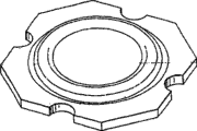
Figure 15 represents the backplan of alternative actuator according to an embodiment of the invention;
Figure 16 represents the top view of the actuator among Figure 15;
Figure 17 represents that the end of the actuator shown in Figure 15 and 16 looks cross-sectional view.
Embodiment
Below with reference to Fig. 2-4 explanation principle of the present invention.
Fig. 2 represents how photoconductive tube 2 can be used to the light from transmitter 4 (for example infrared or visible light LED) is reflexed to receiver 6 (for example, photodetector (photo detector)).Absolute index of refraction (the n of photoconductive tube
1) absolute index of refraction (n of big air thereon
2).Can obtain the critical angle (θ of whole internal reflection according to the Snell law
c), the angle of refracted ray is 90 ° of angles.This provides: sin θ
c=n
2/ n
1, n wherein
1N
2n
1And n
2Between big more (that is relative index of refraction n, of difference
*=n
2/ n
1More little), critical angle is more little, causes more rays with greater than θ
cAngle impact surface part 8, and by internal reflection.
How the effect on the surface that Fig. 3 has represented to make actuator 10 touch photoconductive tube 2 is reduced to the light of receiver 6.The absolute index of refraction of actuator material is greater than the absolute index of refraction of air.Therefore, relative index of refraction n
*Be increased, critical angle increases, and has changed the reflectivity properties of photoconductive tube.Actuator not with situation that photoconductive tube contacts under, exist than big difference between the refractive index of photoconductive tube and air, cause most light in photoconductive tube by internal reflection.When actuator touched photoconductive tube surperficial, the refractive index of actuator and the refractive index of photoconductive tube be near mating manyly, so the light of much less is by internal reflection, and the output signal of reception is significantly reduced.Fig. 4 represents how the output voltage of photodetector reduces when actuator contact photoconductive tube surface.
With reference now to Fig. 5-8 explanation one embodiment of the present of invention.
Fig. 5 represents how LED and photodetector can be arranged to produce guider.Opposing L ED is selected an earth pulsation, and photodetector is measured the internal reflection level from photoconductive tube.
Fig. 6 represents how the actuator 10 with semispherical surface can be placed on photoconductive tube 2 tops, and does not contact with photoconductive tube 2.Air is placed between actuator and the photoconductive tube, but can utilize some other gas/liquid that are different from air.Than air (perhaps other gas/liquid) height, still make by the material (for example silicone) lower than the refractive index of photoconductive tube by absolute index of refraction for actuator.Actuator can position (shown in Fig. 6) that it separates with photoconductive tube to the upper surface of its direct adjacent light conduit or and the photoconductive tube position contacting between move.Actuator can be a rigidity, and by the travel mechanism such as linkwork, can move between first and second positions.On the other hand, actuator can be made by deformable material, so that can move between the primary importance and the second place.Make actuator be partial to primary importance, so that when the user did not push actuator, actuator was shifted to primary importance automatically.In one embodiment, actuator is made by silicone rubber.
Fig. 7 represents to contact actuator and how to cause semispherical surface contact photoconductive tube surface.Be at actuator under the situation of the second place, relative index of refraction is increased, and the quantity of reflection ray is lowered.Thereby the output voltage of photodetector reduces.
Fig. 8 is illustrated in during the cursor navigation, shakes the actuator button and how to cause semispherical surface to roll along the photoconductive tube surface.Come the minimizing of auto-correlation LED to be used to calculate the position of the area on the described surface of contact subsequently by the quantity of the light of waveguide internal reflection.The position of described area is used to calculate the position (for example position on display) with controlling object subsequently.In addition, when deformable material was used for actuator, the size that changes the pressure that is used to navigate can change the size of the area that contacts with photoconductive tube, reduces the quantity of the light of photoconductive tube internal reflection once more.So this system is pressure-sensitive.Susceptibility to pressure depends on the type of material that is used for actuator, and harder material is not too responsive to pressure, and softer material is more responsive to pressure.So, can how responsive according to expecting that this device have pressure, select the type of material of actuator according to specific realization.On the other hand, can change the interior pressure sensibility of single device.In this case, if the user wishes that this device does not have pressure-sensitive, can select a kind of like this setting so, so that controller is according to the central point of the area that calculates contact photoconductive tube surface, and handles information from photodetector according to the mode of the position (for example position on display) of this contact central point controlling object.On the other hand, select pressure-sensitive the setting can cause this equipment to work, so that for example work as, when bigger area contacts photoconductive tube, by the speed increase of object on display of device control owing to increase to the actuator applied pressure.Thereby when the user promoted actuator left, the object on the display was moved to the left.If the user increases pressure, contact area increases so, and in response, the object on the display is moved to the left quickly.
In the above in a kind of constructive alternative with reference to the structure of figure 6-8 explanation, primary importance (promptly, rest position) can be defined by as shown in Figure 7, so that under its non-actuating/stationary state, actuator is the photoconductive tube of heart position contact therein for example, by shaking actuator as shown in Figure 8, the position of object is calculated and is controlled.This constructive alternative does not need to push actuator.Actuator contacts (but a part of actuator still can from moving to and the photoconductive tube position contacting with the photoconductive tube position spaced) all the time with photoconductive tube.This can improve user function and improve reaction time when for example playing games.
Fig. 9 represents an alternative, wherein is provided with grating 12 on photoconductive tube, so that improve the efficient of system.Grating is set on photoconductive tube has changed effective incident angle, allow more internal reflection.How Figure 10 graphic extension photoconductive tube can be used for changing incident angle, and the influence of the amount of light of birefringence that as a result of obtains and internal reflection.When incident angle increased, the quantity of the refract light by the interface reduced, and the quantity of the light of internal reflection increases, till all light are by internal reflection.Therefore, can provide photoconductive tube to increase effective incident angle, thereby increase quantity, improve the efficient of system to the light of sensor internal reflection.
Figure 11 has represented the optical analogy operating rod that works in the manner described above, and it comprises actuator member, and described actuator member has the top 14 that is the operating rod form of actuating for the user.Described actuator member has the sidewall 16 of supporting operating rod part.Sidewall 16 deformables, thus allow operating rod partly to move up and down and move left and right.Actuator member has bottom 18, and bottom 18 comprises and is used to contact the basic of light distribution layer 20 (photoconductive tube) is hemispheric surface, and the upper surface of light distribution layer 20 is arranged to contiguous semispherical surface, and separates certain distance with it.When the user actuates operating rod part 14, sidewall 16 deformables, the upper surface of semispherical surface contact light distribution layer.Optical module layer 22 is disposed in the downside of light distribution layer, and described downside is relative with described upside.The optical module layer comprises and is respectively applied for one or more transmitters and the one or more receiver that light is transmitted into the light distribution layer and receives light from the light distribution layer.
Figure 12 has represented that actuator member wherein is the alternative of the form of knob or disk 24.Knob/disk 24 is disposed on the deformable component 26, and deformable component 26 has the center section 8 by sidewall 30 supportings.At least one of sidewall and center section are deformable.Preferably sidewall and center section all are deformable.Center section has the lower surface that contacts with light distribution layer 20 (photoconductive tube), and is arranged to upper surface contiguous with lower surface and that separate.When the user actuates disk/knob, deformable component distortion, the upper surface of lower surface contact light distribution layer.Optical module layer 22 is disposed in the downside of light distribution layer, and described downside is opposite with described upside.The optical module layer comprises and is respectively applied for transmitter and the receiver that light is transmitted into the light distribution layer and receives light from the light distribution layer.
Figure 13 and 14 is represented top view and the backplan for the printed-wiring board (PWB) of the optical analogy guider use that illustrates previously respectively.Printed-wiring board (PWB) 32 comprises the optical module with discrete optical assembly, highly is preferably 1.6 millimeters or littler, and preferable is to be 1.3 millimeters or littler, preferably is about 1.1 millimeters or littler.The area of printed-wiring board (PWB) is preferably 20mm * 20mm or littler, and preferable is to be 15mm * 15mm, is preferably 12mm * 12mm or littler.Therefore, provide a kind of very little, very thin optical devices that supply the usefulness of mobile product.
Figure 15 and Figure 16 have represented the backplan and the top view of alternative actuator according to an embodiment of the invention respectively.Figure 17 represents that the end of the embodiment shown in Figure 15 and 16 looks cross-sectional view.In the present embodiment, the semispherical surface of actuator has the cruciform that cuts out therein, and described cruciform can improve precision.In alternative, the actuator shape can be different from semisphere, elliptical area for example, parabola, hyperboloid, double-curved surface etc.
According to a further aspect in the invention, the principle about analogue navigation device explanation can be applied to keying device above, the keypad of telephone set for example, keyboard on the game machine or buttons/keys.Such device can comprise as the button of actuator or can comprise a button and the independent actuator that is arranged under the described button.Photoconductive tube is set under button/actuator, button actuate the variation that causes relative index of refraction, as above described like that about guider.In having the device of a plurality of buttons, actuating of different key will cause contacting photoconductive tube in different positions, thereby change the light signal that receiver receives.Show the signal which button is pressed thereby receiver is exportable.Each button can have different functions.
Though at large represent and the present invention be described with reference to the preferred embodiments of the present invention, but skilled in the art will recognize that under the situation that does not break away from the scope of the present invention that limits by additional claim, can make the various variations of form and details aspect.
Claims (35)
Applications Claiming Priority (2)
| Application Number | Priority Date | Filing Date | Title |
|---|---|---|---|
| GB0330055A GB2409515A (en) | 2003-12-24 | 2003-12-24 | Analogue navigation device utilising differing refractive indices |
| GB0330055.5 | 2003-12-24 |
Publications (2)
| Publication Number | Publication Date |
|---|---|
| CN1898635A CN1898635A (en) | 2007-01-17 |
| CN100470456C true CN100470456C (en) | 2009-03-18 |
Family
ID=31503202
Family Applications (1)
| Application Number | Title | Priority Date | Filing Date |
|---|---|---|---|
| CNB2004800385422A Expired - Fee Related CN100470456C (en) | 2003-12-24 | 2004-12-21 | Analog navigation device, handheld electronic device, navigation method and key control device |
Country Status (6)
| Country | Link |
|---|---|
| US (1) | US20070147731A1 (en) |
| EP (1) | EP1697825A1 (en) |
| KR (1) | KR100871453B1 (en) |
| CN (1) | CN100470456C (en) |
| GB (1) | GB2409515A (en) |
| WO (1) | WO2005066754A1 (en) |
Families Citing this family (15)
| Publication number | Priority date | Publication date | Assignee | Title |
|---|---|---|---|---|
| EP1907918A2 (en) | 2005-07-05 | 2008-04-09 | O-Pen ApS | A touch pad system |
| US8013845B2 (en) | 2005-12-30 | 2011-09-06 | Flatfrog Laboratories Ab | Optical touch pad with multilayer waveguide |
| US8031186B2 (en) | 2006-07-06 | 2011-10-04 | Flatfrog Laboratories Ab | Optical touchpad system and waveguide for use therein |
| US8094136B2 (en) | 2006-07-06 | 2012-01-10 | Flatfrog Laboratories Ab | Optical touchpad with three-dimensional position determination |
| US9063617B2 (en) | 2006-10-16 | 2015-06-23 | Flatfrog Laboratories Ab | Interactive display system, tool for use with the system, and tool management apparatus |
| DE102007040294B4 (en) * | 2007-08-24 | 2020-07-09 | Huf Hülsbeck & Fürst Gmbh & Co. Kg | Handle device |
| FI124221B (en) * | 2009-04-24 | 2014-05-15 | Valtion Teknillinen | User input device and associated manufacturing method |
| US8436833B2 (en) | 2009-11-25 | 2013-05-07 | Corning Incorporated | Methods and apparatus for sensing touch events on a display |
| CN102195634A (en) * | 2010-03-10 | 2011-09-21 | 樱花卫厨(中国)股份有限公司 | Infrared touch key |
| CN103902109B (en) * | 2014-03-20 | 2017-09-29 | 京东方科技集团股份有限公司 | Touch-screen, display panel and display device |
| FR3030797B1 (en) | 2014-12-17 | 2018-05-11 | Thales | KEYBOARD WITH IMPROVED RELIABILITY |
| US10372155B2 (en) * | 2017-08-20 | 2019-08-06 | Pixart Imaging Inc. | Joystick and related control method |
| US10684699B2 (en) * | 2018-08-01 | 2020-06-16 | Lite-On Electronics (Guangzhou) Limited | Illuminating keyboard |
| CN109617546A (en) * | 2019-01-18 | 2019-04-12 | 深圳市源隆光学科技有限公司 | Keyboard |
| US11536621B2 (en) * | 2020-03-31 | 2022-12-27 | Toyota Research Institute, Inc. | Methods and systems for calibrating deformable sensors using camera |
Citations (7)
| Publication number | Priority date | Publication date | Assignee | Title |
|---|---|---|---|---|
| US4254333A (en) * | 1978-05-31 | 1981-03-03 | Bergstroem Arne | Optoelectronic circuit element |
| DE3306941A1 (en) * | 1983-02-28 | 1984-08-30 | Joachim Dipl.-Ing. 6486 Brachttal Horst | Dielectric switch arrangement |
| CN1116310A (en) * | 1994-05-12 | 1996-02-07 | 株式会社东金 | Electric field sensor |
| US6028978A (en) * | 1996-12-16 | 2000-02-22 | Ngk Insulators, Ltd. | Display device having a colored layer disposed between a displacement transmitting section and an optical waveguide plate |
| US6154586A (en) * | 1998-12-24 | 2000-11-28 | Jds Fitel Inc. | Optical switch mechanism |
| CN1433521A (en) * | 2000-02-02 | 2003-07-30 | 3M创新有限公司 | Triple layer anti reflective coating for touch screen |
| US6642913B1 (en) * | 1999-01-20 | 2003-11-04 | Fuji Photo Film Co., Ltd. | Light modulation element, exposure unit, and flat-panel display unit |
Family Cites Families (11)
| Publication number | Priority date | Publication date | Assignee | Title |
|---|---|---|---|---|
| US4365862A (en) * | 1980-01-18 | 1982-12-28 | Nippon Telegraph & Telephone Public Corporation | Optical switch |
| US4480182A (en) * | 1982-03-16 | 1984-10-30 | Burroughs Corporation | Single plane optical membrane switch and keyboard |
| DD219076A3 (en) * | 1982-12-03 | 1985-02-20 | Hermsdorf Keramik Veb | COUNTER |
| US4593191A (en) * | 1982-12-29 | 1986-06-03 | At&T Bell Laboratories | Pressure and optical sensitive device with deformable protrusions |
| JP2986773B2 (en) * | 1998-04-01 | 1999-12-06 | 嶋田プレシジョン株式会社 | Light guide plate for point light source |
| US6369800B1 (en) * | 1998-04-03 | 2002-04-09 | Ericsson Inc. | Method and apparatus for use with a keypad of an electronic device |
| US6556149B1 (en) | 1999-03-01 | 2003-04-29 | Canpolar East Inc. | Switches and joysticks using a non-electrical deformable pressure sensor |
| JP2000311053A (en) * | 1999-04-27 | 2000-11-07 | Nec Corp | Position measuring method and position input device using contact point of curved surface |
| US6844871B1 (en) * | 1999-11-05 | 2005-01-18 | Microsoft Corporation | Method and apparatus for computer input using six degrees of freedom |
| US20020020808A1 (en) * | 2000-06-29 | 2002-02-21 | Takumi Kado | Optical touch switcing device |
| GB2367346B (en) * | 2000-09-28 | 2004-07-14 | Nokia Mobile Phones Ltd | Control device |
-
2003
- 2003-12-24 GB GB0330055A patent/GB2409515A/en not_active Withdrawn
-
2004
- 2004-12-21 CN CNB2004800385422A patent/CN100470456C/en not_active Expired - Fee Related
- 2004-12-21 WO PCT/IB2004/004388 patent/WO2005066754A1/en not_active Ceased
- 2004-12-21 EP EP04806547A patent/EP1697825A1/en not_active Withdrawn
- 2004-12-21 US US10/583,986 patent/US20070147731A1/en not_active Abandoned
- 2004-12-21 KR KR1020067012271A patent/KR100871453B1/en not_active Expired - Fee Related
Patent Citations (7)
| Publication number | Priority date | Publication date | Assignee | Title |
|---|---|---|---|---|
| US4254333A (en) * | 1978-05-31 | 1981-03-03 | Bergstroem Arne | Optoelectronic circuit element |
| DE3306941A1 (en) * | 1983-02-28 | 1984-08-30 | Joachim Dipl.-Ing. 6486 Brachttal Horst | Dielectric switch arrangement |
| CN1116310A (en) * | 1994-05-12 | 1996-02-07 | 株式会社东金 | Electric field sensor |
| US6028978A (en) * | 1996-12-16 | 2000-02-22 | Ngk Insulators, Ltd. | Display device having a colored layer disposed between a displacement transmitting section and an optical waveguide plate |
| US6154586A (en) * | 1998-12-24 | 2000-11-28 | Jds Fitel Inc. | Optical switch mechanism |
| US6642913B1 (en) * | 1999-01-20 | 2003-11-04 | Fuji Photo Film Co., Ltd. | Light modulation element, exposure unit, and flat-panel display unit |
| CN1433521A (en) * | 2000-02-02 | 2003-07-30 | 3M创新有限公司 | Triple layer anti reflective coating for touch screen |
Also Published As
| Publication number | Publication date |
|---|---|
| KR100871453B1 (en) | 2008-12-03 |
| GB0330055D0 (en) | 2004-02-04 |
| WO2005066754A1 (en) | 2005-07-21 |
| GB2409515A (en) | 2005-06-29 |
| EP1697825A1 (en) | 2006-09-06 |
| KR20060103532A (en) | 2006-10-02 |
| US20070147731A1 (en) | 2007-06-28 |
| CN1898635A (en) | 2007-01-17 |
Similar Documents
| Publication | Publication Date | Title |
|---|---|---|
| CN100470456C (en) | Analog navigation device, handheld electronic device, navigation method and key control device | |
| US6985138B2 (en) | Input writing device | |
| JP4078027B2 (en) | Optical pointing device | |
| US5675361A (en) | Computer keyboard pointing device | |
| US5771037A (en) | Computer display cursor controller | |
| JP4065035B2 (en) | 3D cursor position setting device | |
| EP0653725B1 (en) | Co-ordinate input device | |
| KR101666995B1 (en) | Multi-telepointer, virtual object display device, and virtual object control method | |
| US7081883B2 (en) | Low-profile multi-channel input device | |
| US20110221676A1 (en) | Optical mouse with touch sensitive top | |
| US8614675B2 (en) | Automatic mode determination for an input device | |
| US6762751B2 (en) | Optical pointing device | |
| US20110037695A1 (en) | Ergonomic control unit for providing a pointing function | |
| US6307535B1 (en) | Pointing device for use in a computer system | |
| WO1995000897A1 (en) | Cursor control device | |
| SK500772010U1 (en) | Pencil input computer peripheral controller | |
| KR20060017512A (en) | Multifunction floating button | |
| US20130257809A1 (en) | Optical touch sensing apparatus | |
| US5579032A (en) | Pointing device for a computer system | |
| CN112237736A (en) | Using touch sensing to make a trackball behave like a joystick | |
| KR100802456B1 (en) | Fixed mouse | |
| KR100791102B1 (en) | Touchpad type remote control | |
| TWI603231B (en) | Cursor control device and method | |
| WO2010020986A2 (en) | An ergonomic control unit for providing a pointing function | |
| KR20170103312A (en) | Pen mouse device |
Legal Events
| Date | Code | Title | Description |
|---|---|---|---|
| C06 | Publication | ||
| PB01 | Publication | ||
| C10 | Entry into substantive examination | ||
| SE01 | Entry into force of request for substantive examination | ||
| C14 | Grant of patent or utility model | ||
| GR01 | Patent grant | ||
| C17 | Cessation of patent right | ||
| CF01 | Termination of patent right due to non-payment of annual fee |
Granted publication date: 20090318 Termination date: 20111221 |