CN100460212C - Ink cartridges and recording devices - Google Patents
Ink cartridges and recording devices Download PDFInfo
- Publication number
- CN100460212C CN100460212C CNB2006100015375A CN200610001537A CN100460212C CN 100460212 C CN100460212 C CN 100460212C CN B2006100015375 A CNB2006100015375 A CN B2006100015375A CN 200610001537 A CN200610001537 A CN 200610001537A CN 100460212 C CN100460212 C CN 100460212C
- Authority
- CN
- China
- Prior art keywords
- ink cartridge
- ink
- wall
- connection terminal
- printer
- Prior art date
- Legal status (The legal status is an assumption and is not a legal conclusion. Google has not performed a legal analysis and makes no representation as to the accuracy of the status listed.)
- Expired - Fee Related
Links
- 238000003780 insertion Methods 0.000 claims description 24
- 230000037431 insertion Effects 0.000 claims description 24
- 238000005192 partition Methods 0.000 claims description 21
- 238000009434 installation Methods 0.000 claims description 19
- 239000000976 ink Substances 0.000 description 288
- 239000000758 substrate Substances 0.000 description 17
- 238000012423 maintenance Methods 0.000 description 6
- 238000000034 method Methods 0.000 description 4
- 230000002265 prevention Effects 0.000 description 3
- 238000000926 separation method Methods 0.000 description 3
- 239000000969 carrier Substances 0.000 description 2
- 239000003086 colorant Substances 0.000 description 2
- 230000006870 function Effects 0.000 description 2
- 238000010438 heat treatment Methods 0.000 description 2
- 238000011900 installation process Methods 0.000 description 2
- 238000004519 manufacturing process Methods 0.000 description 2
- 239000011148 porous material Substances 0.000 description 2
- 230000006837 decompression Effects 0.000 description 1
- 230000001419 dependent effect Effects 0.000 description 1
- 238000001514 detection method Methods 0.000 description 1
- 230000005389 magnetism Effects 0.000 description 1
- 230000001681 protective effect Effects 0.000 description 1
Images


Landscapes
- Ink Jet (AREA)
Abstract
一种墨盒(210),安装在记录装置中,向记录装置提供墨水,它具有:内部贮存墨水的墨盒主体(220);具有墨水供给孔的墨水供给部分(240),设置在墨盒主体(220)的底面(222)上,其位置偏向于与墨盒主体(220)的底面(222)相交的第1侧壁(224);信息存储部分(260),具有连接端子部分(262),该连接端子部分(262)设置在与墨盒主体(220)的底面(222)相交、同时与第1侧壁(224)相对的第2侧壁(226)上;定位部分(280),从第2侧壁(226)伸出,使墨盒(210)向记录装置安装时,使墨盒(210)相对于记录装置定位。这种墨盒的连接端子部分和记录装置一侧的连接端子确保准确地连接,同时增加连接端子的设置位置的自由度。
An ink cartridge (210), which is installed in a recording device and supplies ink to the recording device, has: an ink cartridge main body (220) storing ink inside; an ink supply part (240) having an ink supply hole, arranged on the ink cartridge main body (220) ) on the bottom surface (222), its position is biased to the first side wall (224) intersecting with the bottom surface (222) of the ink cartridge main body (220); the information storage part (260) has a connection terminal part (262), the connection The terminal portion (262) is arranged on the second side wall (226) that intersects with the bottom surface (222) of the ink cartridge main body (220) and is opposite to the first side wall (224) simultaneously; the positioning portion (280), from the second side The wall (226) extends to position the ink cartridge (210) relative to the recording device when the cartridge (210) is installed in the recording device. The connection terminal portion of such an ink cartridge and the connection terminal on the side of the recording apparatus ensure accurate connection while increasing the degree of freedom in the arrangement position of the connection terminal.
Description
技术领域 technical field
本发明涉及一种给记录装置供给墨水的墨盒以及记录装置,所述的记录装置具有:能够自由装卸墨盒的载体和装载在该载体内的记录头。具体地说,本发明涉及一种通过正确安装在记录装置上而向记录装置供给墨水的墨盒。The present invention relates to an ink cartridge for supplying ink to a recording device, and the recording device. The recording device has a carrier capable of freely attaching and detaching the ink cartridge and a recording head mounted in the carrier. More particularly, the present invention relates to an ink cartridge that supplies ink to a recording device by being properly mounted on the recording device.
背景技术 Background technique
通常,作为记录装置的喷墨式打印机,放置在供纸托盘上的用纸等打印媒体通过进纸机构一张一张地进纸,通过用纸运送装置,在副扫描方向上间隙性地按给定量进行送进,同时装载有记录头的载体沿主扫描方向进行往复移动,通过该记录头向印刷媒体上射出墨滴而记录文字和图像。通常,在全彩喷墨式打印机的载体中,独立地安装有贮存黑色墨水的墨盒和贮存黄色、青色、品红色等各色墨水的墨盒。Generally, in an inkjet printer as a recording device, printing media such as paper placed on a paper feed tray are fed one by one by a paper feeding mechanism, and are intermittently pressed in the sub-scanning direction by a paper conveying device. While feeding a given amount, the carrier on which the recording head is mounted reciprocates in the main scanning direction, and the recording head shoots ink droplets onto the printing medium to record characters and images. Generally, in a carrier of a full-color inkjet printer, an ink cartridge for storing black ink and an ink cartridge for storing ink of each color such as yellow, cyan, and magenta are separately installed.
对于载体来说,因为记录头的维护率很高,所以把装载记录头的头装载部分和安装墨盒的盒安装部分设置成可以分离的结构。于是,在墨盒中安装有用于存储制造年月日、型号、墨水剩余量等与墨水有关信息的存储装置,通过这个存储装置和连接器而与记录头相连接的电路基板被设置在载体的头装载部分中。于是,和记录装置之间,设计成可以收发与该墨水有关的信息。这个用于存储信息的存储装置的一例是接触式信息存储部分,该接触式信息存储部分具有:露出外面的连接端子部分和与该连接端子电气连接的存储装置部分。该连接端子通过与记录装置侧的连接端子相接触而构成电气连接。存储部分用来存储与墨水等有关的信息(例如,参照专利文献1)。As for the carrier, since the maintenance rate of the recording head is high, a head loading portion for loading the recording head and a cartridge mounting portion for mounting the ink cartridge are provided in a separable structure. Then, a storage device for storing ink-related information such as the date of manufacture, model, ink remaining amount, etc. is installed in the ink cartridge, and the circuit board connected to the recording head through the storage device and the connector is arranged on the head of the carrier. in the loading section. Therefore, it is designed to be able to send and receive information about the ink to and from the recording device. An example of this storage device for storing information is a contact-type information storage portion having a connection terminal portion exposed to the outside and a storage device portion electrically connected to the connection terminal. The connection terminal is electrically connected by being in contact with the connection terminal on the recording device side. The storage section is used to store information related to ink and the like (for example, refer to Patent Document 1).
专利文献1
国际公开第99/59823号小册子International Publication No. 99/59823 Pamphlet
发明内容 Contents of the invention
对于上述以前的喷墨式打印机,墨盒的信息存储部分的连接端子部分与记录装置侧的连接端子并不能准确地接触,不能正确地接受和发送信息。尤其是若干小面积连接端子区域邻接设置的时候,与记录装置侧的连接端子的位置的结合必须非常准确。In the above-mentioned conventional inkjet printers, the connection terminals of the information storage part of the ink cartridge and the connection terminals of the recording device cannot be accurately contacted, and information cannot be received and transmitted correctly. In particular, when several small-area connection terminal regions are adjacently arranged, the connection with the position of the connection terminal on the recording device side must be very accurate.
同时,对于以前的喷墨式打印机来说,因为电路基板设置在载体的头装载部分中,所以,在把记录头从装置主体中取出来进行维护的时候,常常担心会产生破损。Meanwhile, with conventional inkjet printers, since the circuit board is provided in the head loading portion of the carrier, there is often a fear of damage when the recording head is taken out from the device main body for maintenance.
本发明的目的是提供一种墨盒,该墨盒的信息存储部分的连接端子部分和记录装置侧的连接端子能够准确地接触。An object of the present invention is to provide an ink cartridge in which a connection terminal portion of an information storage portion and a connection terminal on a recording device side can be accurately contacted.
而且,本发明的另一个目的是提供一种墨盒,该墨盒的连接端子部分及记录装置侧的连接端子的安装位置具有一定的自由度。Furthermore, another object of the present invention is to provide an ink cartridge having a certain degree of freedom in the mounting positions of the connection terminal portion of the ink cartridge and the connection terminal on the recording device side.
同时,本发明的再一个目的是提供一种记录装置,其中,读写墨盒的墨水信息的元件固定在一个基板上,当对记录头进行维护的时候,能够保护该基板。Meanwhile, it is still another object of the present invention to provide a recording apparatus in which elements for reading and writing ink information of an ink cartridge are fixed on a substrate, which can be protected when the recording head is maintained.
技术解决方案technical solution
这些目的是通过组合确定保护范围的独立权利要求所述的特征而实现的。同时,从属权利要求限定本发明的更有利的具体例。These objects are achieved by combining the features stated in the independent claims defining the scope of protection. At the same time, the dependent claims define further advantageous embodiments of the invention.
即,在本发明的第一方式中,通过安装到记录装置中而向记录装置提供墨水的墨盒具有:墨盒主体,由底面、与底面相交的第1壁、与该第1壁相对的第2壁所构成,在其内部装有墨水;墨水供给部分,设置在所述底面,具有墨水供给孔;存储元件,设置在所述墨盒主体中、存储与墨水有关的信息;连接端子部分,设置在所述第2壁上、与所述存储元件相连接;定位部分,从所述第2壁伸出,当所述墨盒向记录装置上安装的时候,使所述墨盒相对于记录装置的位置进行定位。That is, in the first aspect of the present invention, the ink cartridge that supplies ink to the recording device by being installed in the recording device has: an ink cartridge main body, a bottom surface, a first wall intersecting the bottom surface, and a second wall opposite to the first wall. The wall is composed of ink inside; the ink supply part is arranged on the bottom surface and has an ink supply hole; the storage element is arranged in the main body of the ink cartridge and stores information related to the ink; the connection terminal part is arranged on the The second wall is connected with the storage element; the positioning part protrudes from the second wall, and when the ink cartridge is installed on the recording device, the position of the ink cartridge relative to the recording device is adjusted. position.
在所述墨盒中,所述墨水供给孔可以设置在所述底面的偏向于所述第1壁的位置上。In the ink cartridge, the ink supply hole may be provided on the bottom surface at a position deviated from the first wall.
在所述墨盒中,所述定位部分可以具有向着所述底面方向伸出的定位肋材(rib)。In the ink cartridge, the positioning portion may have a positioning rib protruding toward the bottom surface.
所述墨盒可以具有凸起部分,该凸起部分设置在比所述连接端子部分及所述定位肋材更上面的一侧。The ink cartridge may have a convex portion provided on an upper side than the connection terminal portion and the positioning rib.
所述墨盒的所述凸起部分所具有的表面的表面位置与所述第1壁大体平行,其中,所述第1壁比所述定位肋材更突出。The position of the surface of the convex portion of the ink cartridge is substantially parallel to the first wall, wherein the first wall protrudes more than the positioning rib.
在所述墨盒中,所述定位肋材可以位于所述连接端子部分的宽之外。In the ink cartridge, the positioning rib may be located outside a width of the connection terminal portion.
在所述墨盒中,对于在至少安装有2个墨盒的记录装置中所使用的墨盒,所述连接端子部分可以设置在偏向于所述两个墨盒邻接的侧壁位置上。In the ink cartridge, for an ink cartridge used in a recording apparatus in which at least two ink cartridges are mounted, the connection terminal portion may be provided at a position biased toward a side wall where the two ink cartridges adjoin.
对于所述墨盒,与所述两个墨盒邻接的所述侧壁相对的侧壁上,可以设有防逆插肋材,使所述墨盒按正规方向进行安装的时候,与所述记录装置相吻合。For the ink cartridges, anti-reverse insertion ribs may be provided on the side wall opposite to the side walls adjacent to the two ink cartridges, so that when the ink cartridges are installed in the normal direction, they will not be in contact with the recording device. match.
在所述墨盒中,对于在至少安装有两个墨盒的记录装置中所使用的墨盒,在与所述两个墨盒邻接的侧壁相对的侧壁上,可以设有防逆插肋材,使所述墨盒按正规方向进行安装的时候,与所述记录装置相吻合。In the ink cartridge, for an ink cartridge used in a recording device in which at least two ink cartridges are installed, an anti-reverse insertion rib may be provided on the side wall opposite to the side wall adjacent to the two ink cartridges, so that When the ink cartridge is installed in the normal direction, it fits with the recording device.
在所述墨盒中,所述连接端子部分设置在所述第2壁上,其位置偏向于与所述底面和所述第2壁两壁相交的第3壁,在与所述第3壁相对的所述第4壁上可以设有防逆插肋材。In the ink cartridge, the connection terminal part is arranged on the second wall, and its position is biased toward the third wall intersecting the bottom surface and the second wall, and opposite to the third wall. Anti-reverse insertion ribs may be provided on the fourth wall.
在本发明的第二方式中,通过安装到记录装置中而向记录装置提供墨水的墨盒具有:墨盒主体,它具有底面、与底面相交的第1壁、与该第1壁相对的第2壁、设置在内部的分隔壁、由分隔壁而分隔成的贮存各种不同墨水的若干墨水室;墨水供给部分,具有墨水供给孔,该墨水供给孔与所述若干墨水室分别对应,设置在所述底面上;信息存储部分,用来存储与贮存在该墨盒主体中的墨水有关的信息;连接端子部分,与所述信息存储部分相连接,设置在所述第2壁上与所述分隔壁相对应的位置上。In a second aspect of the present invention, an ink cartridge for supplying ink to a recording apparatus by being mounted in the recording apparatus has an ink cartridge main body having a bottom surface, a first wall intersecting the bottom surface, and a second wall opposite to the first wall. , a partition wall arranged inside, a plurality of ink chambers for storing various inks separated by the partition wall; the ink supply part has an ink supply hole, and the ink supply hole corresponds to the plurality of ink chambers respectively, and is arranged on the The bottom surface; the information storage part, used to store information related to the ink stored in the ink cartridge main body; the connection terminal part, connected with the information storage part, arranged on the second wall and the partition wall in the corresponding position.
在所述墨盒中,所述墨水供给孔可以设置在所述底面的偏向于所述第1壁一侧的位置上。In the ink cartridge, the ink supply hole may be provided on the bottom surface at a position deviated from the first wall side.
对于在至少安装有两个墨盒的记录装置中所使用的墨盒,所述连接端子部分可以设置在与所述两个墨盒邻接的侧壁相近的所述分隔壁的对应位置上。For an ink cartridge used in a recording apparatus in which at least two ink cartridges are mounted, the connection terminal portion may be provided at a corresponding position of the partition wall adjacent to a side wall where the two ink cartridges adjoin.
对于所述墨盒,在与所述两个墨盒邻接的侧壁相对的侧壁上,可以设有防逆插肋材,使所述墨盒按正规方向安装的时候,与所述记录装置相吻合。For the ink cartridge, an anti-reverse insertion rib may be provided on the side wall opposite to the adjacent side wall of the two ink cartridges, so that when the ink cartridge is installed in the normal direction, it fits with the recording device.
对于在至少安装有两个墨盒的记录装置中所使用的墨盒,在与所述两个墨盒邻接的侧壁相对的侧壁上,可以设有防逆插肋材,使所述墨盒按正规方向安装的时候,与所述记录装置相吻合。For the ink cartridge used in the recording device with at least two ink cartridges installed, on the side wall opposite to the side wall adjacent to the two ink cartridges, anti-reverse insertion ribs can be provided to make the ink cartridges in the normal direction When installed, coincide with the recording device.
在所述墨盒中,所述连接端子部分设置在所述第2壁上,其位置偏向于与所述底面和所述第2壁两壁相交的第3壁,在与所述第3壁相对的所述第4壁上,可以设有防逆插肋材,使所述墨盒按正规方向安装的时候,与所述记录装置相吻合。In the ink cartridge, the connection terminal part is arranged on the second wall, and its position is biased toward the third wall intersecting the bottom surface and the second wall, and opposite to the third wall. Anti-reverse insertion ribs may be provided on the fourth wall of the ink tank, so that when the ink cartridge is installed in the normal direction, it fits with the recording device.
在所述墨盒中,所述连接端子部分的中心设置在偏离所述墨水供给孔的中心轴的位置上。In the ink cartridge, the center of the connection terminal portion is disposed at a position deviated from the central axis of the ink supply hole.
根据本发明的第三方式,为了实现上述目的,本发明的记录装置设有载体,该载体具有装载记录头的头装载部分和安装墨盒的盒安装部分,其特征在于,与所述墨盒的连接端子部分相连接的、用于读写墨水信息的元件被固定在基板上,该基板被设置在所述墨盒安装部分中。于是,在对记录头进行维护的时候,因为头装载部分被设置在装置主体以外,而且读写墨盒中墨水信息的元件固定在基板上,能够随装置主体一起留下,所以,能够起到保护该基板的作用。According to a third aspect of the present invention, in order to achieve the above object, the recording apparatus of the present invention is provided with a carrier having a head mounting portion for mounting a recording head and a cartridge mounting portion for mounting an ink cartridge, characterized in that the connection with the ink cartridge Elements for reading and writing ink information, to which the terminal portions are connected, are fixed on a substrate provided in the ink cartridge mounting portion. Therefore, when the recording head is maintained, because the head loading part is arranged outside the main body of the device, and the components for reading and writing ink information in the ink cartridge are fixed on the substrate and can be left together with the main body of the device, it can protect the recording head. The role of the substrate.
同时,为了实现上述目的,本发明的记录装置具有墨盒能够自由装卸的载体和装载在所述载体上的记录头,其特征在于,在所述记录装置中,读取所述墨盒中墨水信息的元件被固定在基板上,该基板被设置在所述载体前方一侧的内侧壁上。于是,因为固定有读取所述墨盒中墨水信息的元件的基板,离开设置在载体后方一侧的记录头,所以,在对记录头进行维护的时候能够起到保护基板的作用。At the same time, in order to achieve the above object, the recording device of the present invention has a carrier on which the ink cartridge can be freely attached and a recording head mounted on the carrier, and is characterized in that, in the recording device, the information of the ink in the ink cartridge is read The components are fixed on a substrate provided on the inner side wall on the front side of the carrier. Therefore, since the substrate on which the element for reading the ink information in the ink cartridge is fixed is separated from the recording head arranged on the rear side of the carrier, the substrate can be protected when the recording head is maintained.
还有,以上对发明的概述并没有列举出本发明全部特征,这些特征群的另外的组合会构成又一项发明。Also, the above summary of the invention does not list all the features of the present invention, and other combinations of these feature groups will constitute yet another invention.
附图的简要说明Brief description of the drawings
图1是从斜前方看到的、作为本发明实施方式的一种记录装置的喷墨式打印机的整体外部构造的斜视图。1 is a perspective view of the overall external structure of an inkjet printer as a recording device according to an embodiment of the present invention, viewed obliquely from the front.
图2是从斜前方看到的、去掉图1所示的喷墨式打印机100的上部外壳时内部整体构造的斜视图。FIG. 2 is a perspective view of the overall internal structure of the inkjet printer 100 shown in FIG. 1 , viewed obliquely from the front, without the upper casing.
图3是表示图2所示喷墨式打印机的主要部分的截面侧视图。Fig. 3 is a sectional side view showing a main part of the ink jet printer shown in Fig. 2 .
图4是表示图1所示喷墨式打印机的载体的侧视图。Fig. 4 is a side view showing a carrier of the ink jet printer shown in Fig. 1 .
图5是图4所示载体的平面图。FIG. 5 is a plan view of the carrier shown in FIG. 4 .
图6是表示图4所示载体去掉一部分的状态的斜视图。Fig. 6 is a perspective view showing a state in which part of the carrier shown in Fig. 4 is removed.
图7是本发明实施方式的墨盒的一例的上斜视图。Fig. 7 is a top perspective view of an example of an ink cartridge according to an embodiment of the present invention.
图8是墨盒的底斜视图。Fig. 8 is a bottom oblique view of the ink cartridge.
图9A是从第2侧壁一侧看到的墨盒的平面图;图9B是从第3侧壁看到的该墨盒的平面图。Fig. 9A is a plan view of the ink cartridge seen from the second side wall; Fig. 9B is a plan view of the ink cartridge seen from the third side wall.
图10是本发明的实施方式中墨盒的其它例的上斜视图。Fig. 10 is a top perspective view of another example of the ink cartridge in the embodiment of the present invention.
图11是墨盒的底斜视图。Fig. 11 is a bottom oblique view of the ink cartridge.
图12是墨盒的分解斜视图。Fig. 12 is an exploded perspective view of the ink cartridge.
图13A是从第2侧壁看到的墨盒平面图;图13B是从第4侧壁看到的该墨盒的平面图。Fig. 13A is a plan view of the ink cartridge seen from the second side wall; Fig. 13B is a plan view of the ink cartridge seen from the fourth side wall.
图14是安装有两个墨盒的记录装置的载体的上斜视图。Fig. 14 is an upper oblique view of a carrier of a recording device mounted with two ink cartridges.
图15是表示安装在载体里的两个墨盒的位置关系的斜视图。Fig. 15 is a perspective view showing the positional relationship of two ink cartridges mounted in the carrier.
图16A及16B是表示墨盒安装到载体中的过程的部分断面图。16A and 16B are partial sectional views showing the process of mounting the ink cartridge into the carrier.
图17A及17B是表示墨盒安装到载体的过程的另外部分的断面图。17A and 17B are sectional views showing other parts of the process of mounting the ink cartridge to the carrier.
本发明的具体实施方式Specific embodiments of the invention
下面,参照附图对本发明的实施方式进行详细说明。以下的实施方式并不对权利要求书所记载的发明进行限定,而且,实施方式中所说明的特征的组合整体并不是本发明的技术解决方案所必须的。(存储元件保护装置)Hereinafter, embodiments of the present invention will be described in detail with reference to the drawings. The following embodiments do not limit the invention described in the claims, and the entire combination of features described in the embodiments is not essential to the technical solution of the present invention. (memory element protection device)
图1是从斜前方看到的、作为本发明实施方式的一种记录装置的喷墨式打印机的整体外部构造的斜视图。这种喷墨式打印机100具有整体横向延伸的呈长方形的上部外壳101和下部外壳102。上部外壳101和下部外壳102通过卡接(snap)连接在一起的。1 is a perspective view of the overall external structure of an inkjet printer as a recording device according to an embodiment of the present invention, viewed obliquely from the front. This inkjet printer 100 has a rectangular upper casing 101 and a lower casing 102 extending laterally as a whole. The upper shell 101 and the lower shell 102 are connected together by snap.
在上部外壳101后面的一侧具有进纸口103。该进纸口103中设有供纸托盘110和进纸引导装置111,其中,供给的用纸被层叠装载在该供纸托盘110上,该进纸引导装置111被设置在该供纸托盘110一端的一侧。供纸托盘110被设计成向进纸引导装置111后斜上的方向突出,用来保持用纸的倾斜状态。A paper inlet 103 is provided on the rear side of the upper housing 101 . The paper inlet 103 is provided with a
在上部外壳101的前方一侧,设有出纸口104。在出纸口104中设有出纸积纸盘(stacker)120,用来叠装排出用纸。对于出纸积纸盘120可以这样设置:当不使用的时候,能够从出纸口104收容到下部外壳102的里面,使用时可以从出纸口104的斜前上方向抽出,用来保持用纸的倾斜状态。On the front side of the upper housing 101, a paper outlet 104 is provided. A
而且,在出纸口104中设有积纸盘保持部件121,当出纸积纸盘120抽出的时候,使出纸积纸盘120非出纸侧的端部沿横向保持。还有,图1示出了出纸积纸盘120收容在下部外壳102里面时的状态。In addition, a
从上部外壳101的上部到前面设有窗口部件105。该窗口部件105由罩子106所遮盖,该罩子106是透明或者半透明的,并且呈弯曲状,能够自由开闭。通过打开罩子106,能够很容易的进行更换墨盒的作业、维护内部机构作业等。同时,在上部外壳101的左后方一侧设有按钮式的电源开关131和操作开关132。A window member 105 is provided from the upper portion to the front of the upper housing 101 . The window member 105 is covered by a cover 106, which is transparent or semi-transparent, curved, and can be freely opened and closed. By opening the cover 106, the work of replacing the ink cartridge, the maintenance work of the internal mechanism, and the like can be easily performed. Meanwhile, a push-button power switch 131 and an operation switch 132 are provided on the left rear side of the upper housing 101 .
图2是从斜前方看到的、去掉图1所示的喷墨式打印机100的上部外壳时内部整体构造的斜视图;图3是它的主要部分的截面侧视图。如图2所示,在下部外壳102之上,竖直设置构成打印控制器的主基板130,同时,还设有构成打印引擎的记录装置140和用纸供给装置150及运送装置160等(如图3所示)。FIG. 2 is a perspective view of the overall internal structure of the inkjet printer 100 shown in FIG. 1 when viewed obliquely from the front, and FIG. 3 is a cross-sectional side view of its main parts. As shown in Figure 2, on the lower casing 102, a main substrate 130 constituting a print controller is vertically arranged, and meanwhile, a recording device 140 constituting a print engine, a
在主基板130中,安装有图中未示出的CPU、ROM、RAM、ASIC等控制元件、存储元件及其它各种电路元件;在它的上端,突出地设有发光二级管133、134,当按下所述电源开关131和操作开关132的时候,用户通过它们各自的发光来确认开关是否已经处于ON状态。In the main substrate 130, control elements such as CPU, ROM, RAM, ASIC not shown in the figure, storage elements and other various circuit elements are installed; on its upper end, light emitting diodes 133, 134 are prominently arranged , when the power switch 131 and the operation switch 132 are pressed, the user confirms whether the switch is already in the ON state by their respective lights.
记录装置140具有载体141、记录头142、载体马达143、同步皮带144、吸引泵145及检测装置等。在由运送装置160所运送的用纸上,通过载体马达142和同步皮带144,装载在载体141上的记录头进行扫描而进行记录。该记录头142可以由装载在载体141内的、贮存有例如黄色、青色、品红色、黑色共计四种颜色的墨盒146来提供各种颜色的墨水,以便能进行全彩印刷。The recording device 140 has a
供给装置150具有供纸托盘110、进纸引导装置111、进纸滚轮151、储槽(hopper)152、分离凸缘(pad)153等。在供纸托盘110上层叠放置的、通过进纸引导装置111而整齐排列的用纸P,随着进纸滚轮151的转动、储槽152上升,被分离凸缘153压制在进纸滚轮151下,从最上面的用纸P开始进行一张一张地分离,被送到运送装置160中。The
运送装置160具有:送纸滚轮161和从动滚轮162、排纸滚轮163和加热(ギザ)滚轮164、送纸马达165、出纸集纸盘120。从供给装置150供给的用纸P,通过送纸马达165的驱动被夹持在送纸滚轮161和从动滚轮162中,向记录装置140运送,而且,还通过送纸马达165的驱动,被夹持到排纸滚轮163和加热滚轮164中,向出纸集纸盘120运送。The
图4是所述载体141的侧视图,图5是它的平面图,图6是表示在去掉它的某一部分时的斜视图。该载体141具有主体部分141a和外壳部分141b(参照图4、5)。在载体141的主体部分141a的底面,装载有记录头142(参照图4、5),在载体141的主体部分141a的内部,安装有贮存黑色墨水的墨盒146B(参照图6)和贮存有黄色、青色、品红色等各种颜色墨水的墨盒146C(参照图6)。FIG. 4 is a side view of the
同时,在载体141的本体部分141a的背面两侧部分中,以给定的间隔、一体地形成载体导向部分41(参照图4、5)。然后,在与用纸的运送方向成直角的方向上、且同时在垂直的方向上设置的主框架部分107(参照图4)中,形成导向部件43,该导向部件43由所述的载体导向部分41抱持并且滑动(参照图4)。该导向部件43和主框架部分107一样设置,前端的断面形成了弯曲的Z形状。于是,载体导向部分41在导向部件43的弯曲部分之内具有:夹持水平部分43a的一对突起41a、41b,夹持垂直部分43b的一对突起41c、41d。还有,在载体141的本体部分141a的前部一侧的下面的中央部分中,具有一体的滑动部分42(参照图4)。于是,在与用纸的运送方向成直角的方向上、同时在水平的方向上所设置的出纸框架部分108中,所述滑动部分42上具有滑动导向部件44(参照置图4)。Meanwhile, in both side portions of the back surface of the
与以前一样,因为所述载体141的记录头142的维护率非常高,所以,可以把装载记录头142的头装载部分141A和安装墨盒146B、146C的墨盒安装部分141B分开构造。同时,在墨盒安装部分141B的前方一侧的内侧壁上,设有具有连接器147b、147c(参照图6)的电路基板148(参照图6)。As before, since the maintenance rate of the
该电路基板148安装在墨盒146B、146C的前面一侧,并通过连接器147b、147c与存储装置149b、149c(参照图6)连接在一起,其中,存储装置149b、149c存储与墨水的制造年月日、型号、墨水剩余量有关信息,并具有连接器。而且,与记录头142相连接的基板被设置在与电路基板148相分离的头装载部分141A的后面一侧的内侧壁上。This
通过这种构造,记录头142装载在头装载部分141A中,电路基板148设置在墨盒安装部分141B中,当对记录头142进行维护处理时,记录头142和电路基板148能够相互分离,能够对电路基板148起到保护作用。With this configuration, the
而且,在墨盒146B、146C的前面一侧,具有定位用的肋材146Ba、146Ca,当具有连接器的存储装置149b、149c和电路基板148的连接器147b、147c相连接的时候使用。即,该定位用的肋材146Ba、146Ca,在墨盒146B、146C向墨盒141的盒安装部分141B安装的时候,插入到设置在盒安装部分141B前面一侧的沟141Ba、141Bb中,由此,使具有连接器的存储装置149b、149c和电路基板148的连接器147b、147c进行定位。Furthermore, on the front side of the
同时,在墨盒146B、146C的侧面一侧,设有防误装用的肋材146Bb、146Cb,以防止其他形式的载体误装上去。即,当墨盒146B、146C向载体141的盒安装部分141B安装的时候,该防误装用的肋材146Bb、146Cb插入到设置在盒安装部分141B侧面一侧的沟141Ba、141Bb中,使外壳部分141b能够正常关闭;若是其它形式的载体进行安装的时候,因为产生冲突而安装不上,所以,能够防止错误的安装,使该外壳部分能够正常关闭。At the same time, on the side of the
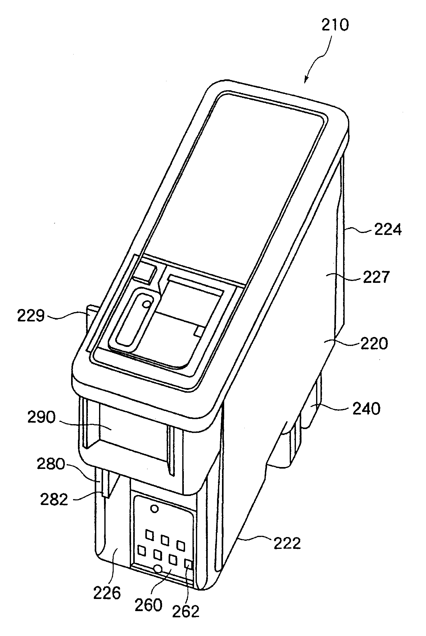
图7是本发明实施方式的墨盒一例的上斜视图。图8是该墨盒的底斜视图。墨盒210具有墨盒主体220、墨水供给部分240、信息存储部分260及定位部分280。Fig. 7 is a top perspective view of an example of an ink cartridge according to an embodiment of the present invention. Fig. 8 is a bottom oblique view of the ink cartridge. The
在墨盒主体部分220的内部贮存有墨水。在该墨盒主体220中例如贮存有黑色墨水。墨盒主体220的一例是,在单一的大体呈长方形的容器主体内,由多孔质材料(图中未示出)所填充,其中,该多孔质材料是由含有墨水的墨水浸渍部件所构成的。但是本发明不局限于此,作为其它的例子,也可以在中空的容器主体中直接贮存墨水,通过设置在墨水供给部分内的阀门等开关装置,有选择地对记录装置进行墨水供给。Ink is stored inside the cartridge
墨水供给部分240具有设置在墨盒主体220的底面222上的墨水供给孔242。墨水供给孔242被设置在墨盒主体220的底面222上,其位置偏向于与该底面222相交的第1侧壁224的一侧。同时,在这里,示出了底面及侧壁的位置关系,并且将设有墨水供给部分240的面确定为底面,但在墨盒210的使用状态下底面必须向下,图中所示的不是使用状态下的情况。The
信息存储部分260具有存储装置,用来存储与墨盒的种类、墨盒所保存的墨水的种类、颜色、墨水的现存量等、以及与墨水相关的信息。信息存储部分260的一例是接触式IC芯片。接触式IC芯片具有基板、具有露出在基板表面一侧的若干接触端的连接端子部分、以及设置在基板里侧的存储装置;通过接触端与外部接触电气连接,读出存储装置的信息数据,从而进行写入交换。The
在本实施方式中,信息存储装置260是接触式的,具有连接端子部分262,该连接端子部分262具有7个露出到外面的接触端。连接端子部分262被设置在与墨盒主体220的底面222相交、同时和第1侧壁224相对的第2侧壁226上。但是,接触式的连接端子部分中的接触端并不只局限于7个。还有,连接端子部分的整体设置在第2侧壁226上,另一方面,信息存储部分260的存储装置被设置在其它侧壁等墨盒主体220合适的位置上,连接端子部分262和信息存储部分的存储装置之间可以用例如挠性印刷电路FPC作为引线而电气连接。而且,不局限于接触式,也可以使用利用磁或者光学的非接触式信息存储部分。In this embodiment, the
图9A是从本实施方式的墨盒210的第2侧壁226看到的平面图。图9B是从该墨盒210的第3侧壁227看到的平面图。在第2侧壁226上设有定位部分280,该定位部分280具有使墨盒210安装到记录装置合适的位置上的功能。定位部分280从第2侧壁226突出,同时具有在底面222方向延伸的定位肋材282。如图9A所示,定位肋材282设置在连接端子部分的宽W1以外的范围。即,定位肋材282的中心线(一点划线)位于连接端子部分的宽W1(两条点划线之间)以外的位置。FIG. 9A is a plan view seen from the
墨盒210具有突出部分290,该突出部分290设置在比信息存储部分260的连接端子部分262及定位肋材282更上面一侧的位置上。突出部分290具有表面292,该表面292比定位肋材282更突出、与第2侧壁大体平行。即,在图9B中,突出部分290的表面292的表面位置(虚线)比定位肋材282(一点划线)及连接端子部分262(2点划线)更突出(图中左侧)。于是,当使用者取出墨盒210的时候,突出部分290与外部接触,能够对连接端子部分262及定位肋材282进行保护,使其免受外部冲击。尤其是,即使当使用者不小心把墨盒210掉在地上,连接端子部分262也不与地面接触,不受损害。The
同时,如图9A所示,连接端子部分262的中心、即图9A的实施例中上列中央的连接端子的纵向的中线,设置在偏离墨水供给孔的中心轴(2点划线)的位置上。连接端子部分262被设置在第2侧壁226上,其位置偏向于与底面222及第2侧面相交的第3侧壁的附近。而且,在墨盒210中,在与偏向于连接端子部分262的第3侧壁相对的第4侧壁上,设有防逆插肋材229。Meanwhile, as shown in FIG. 9A, the center of the
图10是本发明实施方式中所记载的墨盒的其它一例的上斜视图,图11是该墨盒的底斜视图。墨盒310具有墨盒主体320、墨水供给部分340、信息存储部分360、定位部分380。FIG. 10 is a top perspective view of another example of the ink cartridge described in the embodiment of the present invention, and FIG. 11 is a bottom perspective view of the ink cartridge. The
图12是墨盒310的分解斜视图。墨盒主体320的内部具有分隔壁333、335。而且,墨盒主体320具有若干墨水室332、334、336,这些墨水室332、334、336是通过上述分隔壁333、335的分隔而产生的,用于贮存各种不同的墨水。如图12所示的实施方式的墨盒主体320具有3个墨水室,其中,由外壁331和分隔壁333构成了墨水室332,由分隔壁333和分隔壁335构成了墨水室334,由分隔壁335和外壁337构成了墨水室336。这些墨水室中,例如,墨水室332中贮存青色墨水,墨水室334中贮存品红色墨水,墨水室336中贮存黄色墨水。而且,墨盒主体320具有和底面322大体平行的共用顶盖部分339。另外,图12是用于说明分隔壁和墨水室的斜视图,图中省略了存有墨水的多孔质材等其它的构造。FIG. 12 is an exploded perspective view of the
墨水供给部分340设置在与各墨水室332、334、336相对应的墨盒主体310的底面332上,在偏向于与墨盒主体320的底面322相交的第1侧壁324的位置上设有墨水供给孔342、344、346。The
信息存储部件360具有连接端子部分362。连接端子部分362设置在:与墨盒主体320的底面322相交同时相对于第1侧壁324的第2侧壁326上、并且与分隔壁333相对应的位置364上。该信息存储部分360具有与图7所示的墨盒210的信息存储部分263相同的结构和作用,所以,省略了对该部分的说明。The
图13A是从本实施方式的墨盒310的第2侧壁326的侧面看到的平面图。图13B是从该墨盒310的第4侧壁328的侧面看到的平面图。FIG. 13A is a plan view seen from the side of the
如图13A所示,连接端子部分362的中心设置在偏离墨水供给孔的中心轴(2点划线)的位置上。连接端子部分362设置在第2侧壁326上,其位置偏向于与底面322及第2侧壁326的两壁相交的第3侧壁327的附近。如上所述,连接端子部分362被设置在对应于第3侧壁327附近的分隔壁333的位置上。分隔壁333所对应的位置的中心线(1点划线)位于信息存储部分360的连接端子部分362的宽W2(两条虚线之间)的中间。而且,对于该实施方式的墨盒310,连接端子部分362的中心线与分隔壁333所对应的位置的中心线基本上是一致的。As shown in FIG. 13A, the center of the
墨盒310的定位部分380与墨盒210一样,具有从第2侧壁326到底面322方向上延伸的定位肋材382。定位肋材382位于连接端子部分的宽W2以外。即,在图13A中,定位肋材382的中心线(一点划线)位于连接端子部分的宽W2的范围之外。Like the
墨盒310与前实施例中的墨盒210一样,具有凸出部分390,该凸出部分390设置在比信息存储部分360的连接端子部分362及定位肋材382更上面一侧的位置。对于凸出部分390,它的表面位置比定位肋材382突出,具有和第2侧壁326大体平行的表面392。即,在图13B中,凸出部分390的表面392的表面位置(虚线),比定位肋材382(一点划线)及连接端子部分362(2点划线)更突出(图中向左侧的方向)。Like the
在墨盒310中具有防逆插肋材329,该防逆插肋材329设置在偏向于连接端子部分362的第3侧壁所相对的第4侧壁328上。The
图14是安装两个墨盒的记录装置的载体的上斜视图。载体400具有:第1安装部分410和第2安装部分450,其中,第1安装部分安装的是贮存有上述黑色墨水的墨盒210,第2安装部分安装的是贮存有青色、品红色、黄色墨水的墨盒310。Fig. 14 is an upper oblique view of a carrier of a recording device mounted with two ink cartridges. The
在第1安装部分410中,在已经安装有墨盒210时,在信息存储部分260的连接端子部分262所对应的位置上,设有连接端子部分420。而且,在第1安装室410中,在与连接端子部分420相同的侧壁上,在比连接端子部分420离第2安装室更远的位置上,设有与墨盒210的定位肋材282吻合的定位沟430。而且,在第1安装室410相对的第2安装部分450的侧壁上,具有与墨盒210的防逆插肋材282吻合的阶梯部分440。In the first mounting
还有,从图14的方向上看不到,在第1安装室410的底面中,与墨盒210的墨水供给部分240相对应的位置上,设有墨水供给针部分412。墨水供给针部分412具有中空的墨水供给针和端面,该端面位于墨水供给针上并且在载体400的底面一侧。14, the ink supply needle portion 412 is provided at a position corresponding to the
和第1安装部分410一样,第2安装室450中设有连接端子部分460,设置在与已经安装有墨盒310时的信息存储部分360的连接端子部分362相对应的位置上。而且,在第2安装室450中,在与连接端子部分460相同的侧壁上,在比连接端子部分460离第1安装室更远的位置上,设有与墨盒310的定位肋材382吻合的定位沟470。而且,第2安装室450在与第1安装部分410相对的侧壁上,具有与墨盒310的防逆插肋材382吻合的阶梯部分。而且,与第1安装室一样,在第2安装室410的底部设有墨水供给针部分452。墨水供给针部分452的构成与第1安装部分中的墨水供给针部分452是一样的,具有3个墨水供给针,这些墨水供给针分别对应于墨盒310所具有的3个墨水供给孔342、344、346。Like the first mounting
图15是表示安装在载体内的2个墨盒的位置关系的斜视图。如图15所示,墨盒210和墨盒310相邻接地安装在载体400上。这时,墨盒210的第3侧面227和墨盒310的第3侧面327相对。Fig. 15 is a perspective view showing the positional relationship of two ink cartridges mounted in the carrier. As shown in FIG. 15 , the
如上所述,墨盒210的连接端子部分262偏向于第3侧面227,同时,墨盒310的连接端子部分362偏向第3侧面327。即,墨盒210的连接端子部分262和墨盒310的连接端子部分362相邻近,这样安装在载体上。还有,如图14所示的载体400那样,第1安装部分410的连接端子420和第2安装部分450的连接端子460相邻近,这样就不需要用长的FPC等作为引线。As described above, the
而且,如上所述,墨盒210的防逆插肋材229设置在与第3侧面227相对的第4侧面228上,同时,墨盒310的防逆插肋材329设置在与第3侧面327相对的第4侧面328上。即,墨盒210的防逆插肋材229和墨盒310的防逆插肋材329并不是设置在相向的位置上。并且,对于载体400,相邻接的第3侧面227、327彼此以非常近的距离安装,这样能够使载体400整体的体积变小。And, as mentioned above, the
图16A和图16B是表示墨盒向载体中安装过程的部分截面图。图16A和图16B是表示含有定位沟470的平面的载体400的第2安装部分450的断面图。同时,以墨盒310向载体400的第2安装部分450中安装为例进行说明,墨盒210向载体400的第1安装部分450中安装的情况与之相同。16A and 16B are partial sectional views showing the installation process of the ink cartridge into the carrier. 16A and 16B are cross-sectional views showing the second mounting
如图16A所示,墨盒310与载体400的第2安装部分相对,沿正规方向进行配置。这里的正规方向就是墨盒310的墨水供给部分340正对第2安装部分450的墨水供给针部分452的方向,同样也是墨盒310的连接端子部分362正对安装部分450的连接端子部分460的方向。按正规方向进行安装的墨盒310插入到载体400的第2安装部分450中。As shown in FIG. 16A , the
如图16B所示,从图16A的状态开始,当墨盒310插入时,墨盒310的定位肋材382导入到第2安装部分450的定位沟470中。同时,墨盒310的防逆插肋材329被第2安装部分450的阶梯部分480所容纳并且相吻合。As shown in FIG. 16B , from the state of FIG. 16A , when the
而且,当墨盒310插入时,第2安装部分450的墨水供给针部分452插入到墨盒310的墨水供给部分340的内部。墨盒310的墨水供给部分340的端面与第2安装部分450的墨水供给针部分452的端面相接触以后,插入停止。由此,墨盒310通过墨水供给针部分452向记录装置提供墨水。Furthermore, when the
图17A和17B是表示墨盒向载体中安装过程的其他部分截面图。图17A和图17B是表示不含定位沟470的平面的载体400的第2安装部分450的断面图。17A and 17B are other partial sectional views showing the installation process of the ink cartridge into the carrier. 17A and 17B are cross-sectional views showing the second mounting
图17A对应于图16A,表示墨盒310对着载体400的第2安装部分450,按正规方向进行安装时的状态。图17B对应图16B,表示墨盒310安装到载体400的第2安装部分450中的状态。FIG. 17A corresponds to FIG. 16A, and shows the state when the
如图17B所示,墨盒310的墨水供给部分340的端面与第2安装部分450的墨水供给针部分452的端面相接触的时候,墨盒310的突起部分290的下端面与第2安装部分450的表面427相接触。As shown in Figure 17B, when the end face of the
墨盒310的墨水供给针452通过进入到墨水供给部分340中而被定位,同时,定位肋材382通过与定位沟470相吻合也被定位。还有,同样地,通过定位肋材382,第2侧面326也被定位,墨盒310的连接端子部分352在与墨水供给部分340相分离的位置上,和第2安装部分450的连接端子部分460高精度连接。于是,第2安装部分450的连接端子部分460通过和墨盒310的连接端子部分262相接触而获得信息,通过FPC等的配线462,能够准确地向记录装置一侧进行传送。The
而且,墨盒310的定位肋材382设置在连接端子部分的宽W2以外的位置,所以,当墨盒310插入到第2安装部分450内的时候,能够防止定位肋材382损伤第2安装部分450的连接端子部分460。Moreover, the
这里,当墨盒210已经安装上的时候,墨盒310不是按正规方向而是以相反的方向进行安装。即,使第1侧面324向第2安装部分450的连接端子部分460一侧,同时第2侧面326向第2安装部分450的墨水供给针部分452一侧的方向进行墨盒310的安装。在这种状态下,当墨盒310刚要向第2安装部分450中安装的时候,墨盒310的防逆插肋材329与墨盒210相接触。这时就不能再插入墨盒310。所以,能够防止墨盒310以反方向向第2安装部分450内安装。Here, when the
以上,根据本实施方式,设有定位部件,使墨盒在与连接端子部分相同的表面上与记录装置的载体相对而定位,连接端子部分设置在与墨水供给部分相分离的位置上,能够与载体的连接端子部分准确地接触。从而,能够增加设置墨盒的连接端子部分的位置的自由度。As described above, according to the present embodiment, a positioning member is provided to position the ink cartridge against the carrier of the recording device on the same surface as the connection terminal portion, the connection terminal portion is provided at a position separated from the ink supply portion, and can be connected to the carrier. part of the connecting terminal is in accurate contact. Thereby, the degree of freedom of the position where the connection terminal portion of the ink cartridge is provided can be increased.
而且,当把连接端子部分设置在与墨盒主体的分隔壁相对应的位置上时,墨盒经过制造过程中的加工、减压等,墨盒主体不容易产生的变形影响,从而,能够与载体的连接端子部分准确地连接。Moreover, when the connecting terminal portion is arranged at a position corresponding to the partition wall of the ink cartridge main body, the ink cartridge is subjected to processing, decompression, etc. in the manufacturing process, and the ink cartridge main body is not easily affected by deformation, thereby enabling connection with the carrier. The terminal parts are connected accurately.
以上,对本发明的各种实施方式进行了描述,但是本发明并不局限于以上实施方式,在权利要求上所记载的发明范围内,也可以采用其它适用的实施方式。例如,作为记录装置以喷墨式打印机为例进行说明,但是并不局限于此,例如也可以适用于喷墨式传真机、复印机等。Various embodiments of the present invention have been described above, but the present invention is not limited to the above embodiments, and other applicable embodiments can also be adopted within the scope of the invention described in the claims. For example, an inkjet printer has been described as an example of the recording device, but the present invention is not limited thereto, and may be applied to inkjet facsimiles, copiers, and the like, for example.
如以上说明的那样,根据本实施方式,设有定位部件,使墨盒在与连接端子部分相同的表面上与记录装置的载体相对而定位,连接端子部分设置在与墨水供给部分相分离的位置上,能够与记录装置侧的连接端子部分准确地接触。从而,能够增加设置墨盒的连接端子部分的位置的自由度。As described above, according to this embodiment, a positioning member is provided to position the ink cartridge against the carrier of the recording device on the same surface as the connection terminal portion, and the connection terminal portion is provided at a position separated from the ink supply portion. , can be accurately contacted with the connection terminal portion on the recording device side. Thereby, the degree of freedom of the position where the connection terminal portion of the ink cartridge is provided can be increased.
而且,根据本实施方式,在进行记录头的维护处理的时候,头装载部分设置在装置主体以外,读写与墨盒的墨水有关的信息的元件固定在基板上,该基板能够留在装置主体上,所以,能够对该基板起到保护作用。Moreover, according to the present embodiment, when the maintenance process of the recording head is performed, the head mounting part is provided outside the apparatus main body, and the elements for reading and writing information related to the ink of the ink cartridge are fixed on the substrate, and the substrate can be left on the apparatus main body. , so it can protect the substrate.
Claims (12)
Applications Claiming Priority (4)
| Application Number | Priority Date | Filing Date | Title |
|---|---|---|---|
| JP2002093838 | 2002-03-29 | ||
| JP2002093838 | 2002-03-29 | ||
| JP2002099211 | 2002-04-01 | ||
| JP2003077849 | 2003-03-20 |
Related Parent Applications (1)
| Application Number | Title | Priority Date | Filing Date |
|---|---|---|---|
| CNB031211798A Division CN1282549C (en) | 2002-03-29 | 2003-03-28 | Ink cartridges and printing devices |
Publications (2)
| Publication Number | Publication Date |
|---|---|
| CN1799847A CN1799847A (en) | 2006-07-12 |
| CN100460212C true CN100460212C (en) | 2009-02-11 |
Family
ID=36810166
Family Applications (2)
| Application Number | Title | Priority Date | Filing Date |
|---|---|---|---|
| CNB2006101274095A Expired - Fee Related CN100513185C (en) | 2002-03-29 | 2003-03-28 | A printing apparatus and ink cartridge pair |
| CNB2006100015375A Expired - Fee Related CN100460212C (en) | 2002-03-29 | 2003-03-28 | Ink cartridges and recording devices |
Family Applications Before (1)
| Application Number | Title | Priority Date | Filing Date |
|---|---|---|---|
| CNB2006101274095A Expired - Fee Related CN100513185C (en) | 2002-03-29 | 2003-03-28 | A printing apparatus and ink cartridge pair |
Country Status (1)
| Country | Link |
|---|---|
| CN (2) | CN100513185C (en) |
Families Citing this family (1)
| Publication number | Priority date | Publication date | Assignee | Title |
|---|---|---|---|---|
| JP6624759B2 (en) | 2015-09-04 | 2019-12-25 | ヒューレット−パッカード デベロップメント カンパニー エル.ピー.Hewlett‐Packard Development Company, L.P. | Interchangeable cartridge with lid manifold |
Citations (5)
| Publication number | Priority date | Publication date | Assignee | Title |
|---|---|---|---|---|
| CN1134886A (en) * | 1995-04-27 | 1996-11-06 | 惠普公司 | Ink supply device for inkjet printer |
| CN1186021A (en) * | 1997-01-30 | 1998-07-01 | 惠普公司 | Its configuration is suitable for ink containers for small ink supply stations |
| CN1272081A (en) * | 1998-05-18 | 2000-11-01 | 精工爱普生株式会社 | Inkjet printing device and its ink cartridge |
| CN1292328A (en) * | 1999-10-12 | 2001-04-25 | 精工爱普生株式会社 | Ink cartridges for inkjet printing devices |
| CN1341515A (en) * | 1993-08-19 | 2002-03-27 | 佳能株式会社 | Ink box and ink-jet device with said ink box |
-
2003
- 2003-03-28 CN CNB2006101274095A patent/CN100513185C/en not_active Expired - Fee Related
- 2003-03-28 CN CNB2006100015375A patent/CN100460212C/en not_active Expired - Fee Related
Patent Citations (5)
| Publication number | Priority date | Publication date | Assignee | Title |
|---|---|---|---|---|
| CN1341515A (en) * | 1993-08-19 | 2002-03-27 | 佳能株式会社 | Ink box and ink-jet device with said ink box |
| CN1134886A (en) * | 1995-04-27 | 1996-11-06 | 惠普公司 | Ink supply device for inkjet printer |
| CN1186021A (en) * | 1997-01-30 | 1998-07-01 | 惠普公司 | Its configuration is suitable for ink containers for small ink supply stations |
| CN1272081A (en) * | 1998-05-18 | 2000-11-01 | 精工爱普生株式会社 | Inkjet printing device and its ink cartridge |
| CN1292328A (en) * | 1999-10-12 | 2001-04-25 | 精工爱普生株式会社 | Ink cartridges for inkjet printing devices |
Also Published As
| Publication number | Publication date |
|---|---|
| CN1799847A (en) | 2006-07-12 |
| CN100513185C (en) | 2009-07-15 |
| CN1911666A (en) | 2007-02-14 |
Similar Documents
| Publication | Publication Date | Title |
|---|---|---|
| JP3666491B2 (en) | Ink cartridge and recording apparatus | |
| US6168262B1 (en) | Electrical interconnect for replaceable ink containers | |
| JP2007261286A (en) | Ink cartridge and recording apparatus | |
| JP4539690B2 (en) | Recording device | |
| CN100460212C (en) | Ink cartridges and recording devices | |
| JP2005028883A (en) | Ink cartridge set | |
| JP4075857B2 (en) | Ink cartridge and recording apparatus | |
| RU2267405C2 (en) | Ink cartridge for mounting into printer and printer (versions) | |
| CA2573238C (en) | A printing apparatus and ink cartridge therefor | |
| AU2007231718B2 (en) | A printing apparatus and ink cartridge therefor | |
| AU2007201742C1 (en) | A printing apparatus and ink cartridge therefor | |
| HK1057876A (en) | A printing apparatus and ink cartridge therefor |
Legal Events
| Date | Code | Title | Description |
|---|---|---|---|
| C06 | Publication | ||
| PB01 | Publication | ||
| C10 | Entry into substantive examination | ||
| SE01 | Entry into force of request for substantive examination | ||
| C14 | Grant of patent or utility model | ||
| GR01 | Patent grant | ||
| CF01 | Termination of patent right due to non-payment of annual fee |
Granted publication date: 20090211 Termination date: 20190328 |
|
| CF01 | Termination of patent right due to non-payment of annual fee |