CN100453695C - Microwave plasma processing apparatus - Google Patents
Microwave plasma processing apparatus Download PDFInfo
- Publication number
- CN100453695C CN100453695C CNB2004800066893A CN200480006689A CN100453695C CN 100453695 C CN100453695 C CN 100453695C CN B2004800066893 A CNB2004800066893 A CN B2004800066893A CN 200480006689 A CN200480006689 A CN 200480006689A CN 100453695 C CN100453695 C CN 100453695C
- Authority
- CN
- China
- Prior art keywords
- microwave
- plasma processing
- plasma
- bottle
- processing chamber
- Prior art date
- Legal status (The legal status is an assumption and is not a legal conclusion. Google has not performed a legal analysis and makes no representation as to the accuracy of the status listed.)
- Expired - Fee Related
Links
Images


Classifications
-
- H—ELECTRICITY
- H01—ELECTRIC ELEMENTS
- H01J—ELECTRIC DISCHARGE TUBES OR DISCHARGE LAMPS
- H01J37/00—Discharge tubes with provision for introducing objects or material to be exposed to the discharge, e.g. for the purpose of examination or processing thereof
- H01J37/32—Gas-filled discharge tubes
- H01J37/32431—Constructional details of the reactor
- H01J37/3244—Gas supply means
-
- C—CHEMISTRY; METALLURGY
- C23—COATING METALLIC MATERIAL; COATING MATERIAL WITH METALLIC MATERIAL; CHEMICAL SURFACE TREATMENT; DIFFUSION TREATMENT OF METALLIC MATERIAL; COATING BY VACUUM EVAPORATION, BY SPUTTERING, BY ION IMPLANTATION OR BY CHEMICAL VAPOUR DEPOSITION, IN GENERAL; INHIBITING CORROSION OF METALLIC MATERIAL OR INCRUSTATION IN GENERAL
- C23C—COATING METALLIC MATERIAL; COATING MATERIAL WITH METALLIC MATERIAL; SURFACE TREATMENT OF METALLIC MATERIAL BY DIFFUSION INTO THE SURFACE, BY CHEMICAL CONVERSION OR SUBSTITUTION; COATING BY VACUUM EVAPORATION, BY SPUTTERING, BY ION IMPLANTATION OR BY CHEMICAL VAPOUR DEPOSITION, IN GENERAL
- C23C16/00—Chemical coating by decomposition of gaseous compounds, without leaving reaction products of surface material in the coating, i.e. chemical vapour deposition [CVD] processes
- C23C16/04—Coating on selected surface areas, e.g. using masks
- C23C16/045—Coating cavities or hollow spaces, e.g. interior of tubes; Infiltration of porous substrates
-
- C—CHEMISTRY; METALLURGY
- C23—COATING METALLIC MATERIAL; COATING MATERIAL WITH METALLIC MATERIAL; CHEMICAL SURFACE TREATMENT; DIFFUSION TREATMENT OF METALLIC MATERIAL; COATING BY VACUUM EVAPORATION, BY SPUTTERING, BY ION IMPLANTATION OR BY CHEMICAL VAPOUR DEPOSITION, IN GENERAL; INHIBITING CORROSION OF METALLIC MATERIAL OR INCRUSTATION IN GENERAL
- C23C—COATING METALLIC MATERIAL; COATING MATERIAL WITH METALLIC MATERIAL; SURFACE TREATMENT OF METALLIC MATERIAL BY DIFFUSION INTO THE SURFACE, BY CHEMICAL CONVERSION OR SUBSTITUTION; COATING BY VACUUM EVAPORATION, BY SPUTTERING, BY ION IMPLANTATION OR BY CHEMICAL VAPOUR DEPOSITION, IN GENERAL
- C23C16/00—Chemical coating by decomposition of gaseous compounds, without leaving reaction products of surface material in the coating, i.e. chemical vapour deposition [CVD] processes
- C23C16/44—Chemical coating by decomposition of gaseous compounds, without leaving reaction products of surface material in the coating, i.e. chemical vapour deposition [CVD] processes characterised by the method of coating
- C23C16/455—Chemical coating by decomposition of gaseous compounds, without leaving reaction products of surface material in the coating, i.e. chemical vapour deposition [CVD] processes characterised by the method of coating characterised by the method used for introducing gases into reaction chamber or for modifying gas flows in reaction chamber
- C23C16/45563—Gas nozzles
- C23C16/45568—Porous nozzles
-
- C—CHEMISTRY; METALLURGY
- C23—COATING METALLIC MATERIAL; COATING MATERIAL WITH METALLIC MATERIAL; CHEMICAL SURFACE TREATMENT; DIFFUSION TREATMENT OF METALLIC MATERIAL; COATING BY VACUUM EVAPORATION, BY SPUTTERING, BY ION IMPLANTATION OR BY CHEMICAL VAPOUR DEPOSITION, IN GENERAL; INHIBITING CORROSION OF METALLIC MATERIAL OR INCRUSTATION IN GENERAL
- C23C—COATING METALLIC MATERIAL; COATING MATERIAL WITH METALLIC MATERIAL; SURFACE TREATMENT OF METALLIC MATERIAL BY DIFFUSION INTO THE SURFACE, BY CHEMICAL CONVERSION OR SUBSTITUTION; COATING BY VACUUM EVAPORATION, BY SPUTTERING, BY ION IMPLANTATION OR BY CHEMICAL VAPOUR DEPOSITION, IN GENERAL
- C23C16/00—Chemical coating by decomposition of gaseous compounds, without leaving reaction products of surface material in the coating, i.e. chemical vapour deposition [CVD] processes
- C23C16/44—Chemical coating by decomposition of gaseous compounds, without leaving reaction products of surface material in the coating, i.e. chemical vapour deposition [CVD] processes characterised by the method of coating
- C23C16/455—Chemical coating by decomposition of gaseous compounds, without leaving reaction products of surface material in the coating, i.e. chemical vapour deposition [CVD] processes characterised by the method of coating characterised by the method used for introducing gases into reaction chamber or for modifying gas flows in reaction chamber
- C23C16/45563—Gas nozzles
- C23C16/45578—Elongated nozzles, tubes with holes
-
- C—CHEMISTRY; METALLURGY
- C23—COATING METALLIC MATERIAL; COATING MATERIAL WITH METALLIC MATERIAL; CHEMICAL SURFACE TREATMENT; DIFFUSION TREATMENT OF METALLIC MATERIAL; COATING BY VACUUM EVAPORATION, BY SPUTTERING, BY ION IMPLANTATION OR BY CHEMICAL VAPOUR DEPOSITION, IN GENERAL; INHIBITING CORROSION OF METALLIC MATERIAL OR INCRUSTATION IN GENERAL
- C23C—COATING METALLIC MATERIAL; COATING MATERIAL WITH METALLIC MATERIAL; SURFACE TREATMENT OF METALLIC MATERIAL BY DIFFUSION INTO THE SURFACE, BY CHEMICAL CONVERSION OR SUBSTITUTION; COATING BY VACUUM EVAPORATION, BY SPUTTERING, BY ION IMPLANTATION OR BY CHEMICAL VAPOUR DEPOSITION, IN GENERAL
- C23C16/00—Chemical coating by decomposition of gaseous compounds, without leaving reaction products of surface material in the coating, i.e. chemical vapour deposition [CVD] processes
- C23C16/44—Chemical coating by decomposition of gaseous compounds, without leaving reaction products of surface material in the coating, i.e. chemical vapour deposition [CVD] processes characterised by the method of coating
- C23C16/50—Chemical coating by decomposition of gaseous compounds, without leaving reaction products of surface material in the coating, i.e. chemical vapour deposition [CVD] processes characterised by the method of coating using electric discharges
- C23C16/511—Chemical coating by decomposition of gaseous compounds, without leaving reaction products of surface material in the coating, i.e. chemical vapour deposition [CVD] processes characterised by the method of coating using electric discharges using microwave discharges
-
- H—ELECTRICITY
- H01—ELECTRIC ELEMENTS
- H01J—ELECTRIC DISCHARGE TUBES OR DISCHARGE LAMPS
- H01J37/00—Discharge tubes with provision for introducing objects or material to be exposed to the discharge, e.g. for the purpose of examination or processing thereof
- H01J37/32—Gas-filled discharge tubes
- H01J37/32009—Arrangements for generation of plasma specially adapted for examination or treatment of objects, e.g. plasma sources
- H01J37/32192—Microwave generated discharge
-
- H—ELECTRICITY
- H05—ELECTRIC TECHNIQUES NOT OTHERWISE PROVIDED FOR
- H05H—PLASMA TECHNIQUE; PRODUCTION OF ACCELERATED ELECTRICALLY-CHARGED PARTICLES OR OF NEUTRONS; PRODUCTION OR ACCELERATION OF NEUTRAL MOLECULAR OR ATOMIC BEAMS
- H05H1/00—Generating plasma; Handling plasma
- H05H1/24—Generating plasma
- H05H1/46—Generating plasma using applied electromagnetic fields, e.g. high frequency or microwave energy
- H05H1/461—Microwave discharges
- H05H1/463—Microwave discharges using antennas or applicators
Landscapes
- Chemical & Material Sciences (AREA)
- Engineering & Computer Science (AREA)
- Physics & Mathematics (AREA)
- Plasma & Fusion (AREA)
- Materials Engineering (AREA)
- Mechanical Engineering (AREA)
- Metallurgy (AREA)
- Organic Chemistry (AREA)
- Chemical Kinetics & Catalysis (AREA)
- General Chemical & Material Sciences (AREA)
- Analytical Chemistry (AREA)
- Spectroscopy & Molecular Physics (AREA)
- Electromagnetism (AREA)
- Chemical Vapour Deposition (AREA)
- Plasma Technology (AREA)
Abstract
Description
技术领域 technical field
本发明涉及微波等离子体处理装置,特别是涉及在塑料容器上形成化学蒸镀膜时能够使等离子体稳定地、且高效率地发生的微波等离子体处理装置。The present invention relates to a microwave plasma processing device, in particular to a microwave plasma processing device capable of stably and efficiently generating plasma when forming a chemical vapor deposition film on a plastic container.
背景技术 Background technique
化学蒸镀法(CVD)是采用在常温下不发生反应的处理用气体,利用高温气氛中的气相生长,在处理对象物的表面使反应生成物膜状析出的技术,广泛使用于半导体的制造、金属和陶瓷的表面改性等。近来,在CVD中,低压等离子体CVD也广泛使用于塑料容器的表面改性,特别是使用于气体阻挡层(gas barrier)性能的提高。Chemical vapor deposition (CVD) is a technology that uses a processing gas that does not react at room temperature, utilizes vapor phase growth in a high-temperature atmosphere, and deposits a reaction product in the form of a film on the surface of the object to be processed. It is widely used in the manufacture of semiconductors. , Surface modification of metals and ceramics, etc. Recently, in CVD, low-pressure plasma CVD is also widely used in the surface modification of plastic containers, especially for the improvement of gas barrier properties.
等离子体CVD是利用等离子体使薄膜生长的技术,基本上是在减压条件下用高电场的电能使包含处理用气体的气体放电,使经过离解、结合生成的物质在气相中或在处理对象物上发生化学反应,以此在处理对象物上堆积的方法。Plasma CVD is a technology that uses plasma to grow thin films. Basically, under reduced pressure, the electric energy of high electric field is used to discharge the gas containing the processing gas, so that the dissociated and combined substances are in the gas phase or in the processing object. A chemical reaction occurs on the object to accumulate on the object to be treated.
等离子体状态是通过辉光放电、电晕放电以及电弧放电实现的,其中,辉光放电的方式已知的有利用直流辉光放电的方法、利用高频辉光放电的方法、和利用微波放电的方法等。The plasma state is realized by glow discharge, corona discharge and arc discharge, among which, the known methods of glow discharge include the method of utilizing direct current glow discharge, the method of utilizing high frequency glow discharge, and the method of utilizing microwave discharge wait.
利用高频辉光放电,在塑料上形成蒸镀碳膜的例子,公开的有在塑料容器的内壁面形成硬质碳膜的涂碳膜塑料容器。An example of forming a vapor-deposited carbon film on plastics by utilizing high-frequency glow discharge discloses a carbon-coated plastic container in which a hard carbon film is formed on the inner wall of the plastic container.
但是,在利用高频辉光放电的等离子体CVD的情况下,有必要使用在容器内部配置内部电极,在容器外部配置外部电极的所谓电容耦合型CVD装置,因此存在装置的结构比较复杂,而且操作也变得复杂的问题。However, in the case of plasma CVD using high-frequency glow discharge, it is necessary to use a so-called capacitive coupling type CVD apparatus in which internal electrodes are arranged inside the container and external electrodes are arranged outside the container. become complicated issues.
而在微波等离子体CVD的情况下,由于利用室内的微波放电,不需要配置外部电极和内部电极,能够使装置的结构变得极其简单。又,装置内的减压程度也只要达到只在塑料容器内能够发生微波放电的程度即可,因此不需要在整个装置内维持高真空,操作简便,而且生产效率高。In the case of microwave plasma CVD, since the microwave discharge in the chamber is used, there is no need to arrange external electrodes and internal electrodes, and the structure of the device can be extremely simplified. In addition, the degree of decompression in the device only needs to be such that microwave discharge can occur only in the plastic container, so it is not necessary to maintain a high vacuum in the entire device, and the operation is simple and the production efficiency is high.
微波放电等离子体是高能电子生成效率优异的等离子体,作为高密度、高反应性等离子体对于等离子体CVD是有用的。Microwave discharge plasma is plasma excellent in the generation efficiency of high-energy electrons, and is useful for plasma CVD as high-density, high-reactivity plasma.
作为以塑料容器为对象的微波等离子体处理方法和装置,已经公开了这样的例子,即例如将瓶子同轴配置于筒状的微波封闭室中,对瓶子的内部和瓶子的外部的空间同时抽气,而且,在规定的处理时间内使处理气体流入瓶子的内部,同时,将微波引入微波封闭室中,在瓶子内部使等离子体点火并维持,对瓶子进行处理的方法。As a microwave plasma treatment method and apparatus for plastic containers, such an example has been disclosed, that is, for example, a bottle is coaxially arranged in a cylindrical microwave closed chamber, and the space inside and outside the bottle is simultaneously extracted. Moreover, the processing gas flows into the inside of the bottle within a specified processing time, and at the same time, microwaves are introduced into the microwave closed chamber, and the plasma is ignited and maintained inside the bottle to treat the bottle.
但是,在使用微波等离子体处理的情况下,在微波的导入与微波的发生之间存在时间滞后,而且,该时间滞后也不是一定的,每一次处理都有相当大变动,因此难于控制处理条件,存在处理效果不稳定的缺点。However, in the case of microwave plasma treatment, there is a time lag between the introduction of microwaves and the generation of microwaves, and this time lag is not constant, and there are considerable fluctuations for each treatment, so it is difficult to control the treatment conditions. , there is a shortcoming that the processing effect is not stable.
又,由于等离子体的状态不稳定,被处理的容器发生局部热变形或不能够形成均匀的薄膜的问题。Also, due to the unstable state of the plasma, there is a problem that the container to be processed is locally thermally deformed or a uniform thin film cannot be formed.
在这里,作为等离子体的点火方法,已知有利用电火花的方法、利用紫外线照射的方法、利用磁场操作的方法等,但是,不管哪一种方法中都存在装置结构复杂的问题。Here, as methods for igniting plasma, there are known methods using spark, ultraviolet irradiation, and magnetic field manipulation. However, any of these methods has a problem of complicated device structure.
又,通过加大引入等离子体处理室的微波的输出,可以加快等离子体的点火,但是,一旦增加微波的输出,基体的处理由于从蒸镀初期阶段开始就利用高能状态的等离子体进行处理,因此处理基体与蒸镀膜之间形成的中间层不能够充分生长,存在处理基体与蒸镀膜之间的紧密结合程度降低的问题。Also, by increasing the output of the microwaves introduced into the plasma processing chamber, the ignition of the plasma can be accelerated. However, once the output of the microwaves is increased, the processing of the substrate will be processed by using the plasma in a high-energy state from the initial stage of evaporation. Therefore, the intermediate layer formed between the treated substrate and the vapor-deposited film cannot grow sufficiently, and there is a problem that the degree of close bonding between the treated substrate and the vapor-deposited film is reduced.
本发明鉴于上述问题,其目的在于提供一种通过使处理用气体高能量效率均匀地等离子体化,能够在处理基体上形成均匀的薄膜,同时能够缩短向等离子体处理室引入微波到等离子体发光为止的时间,而且,能够控制等离子体点火的时刻的微波等离子体处理装置。In view of the above problems, the present invention aims to provide a method that can form a uniform thin film on a processing substrate by uniformly plasmating the processing gas with high energy efficiency, and at the same time shorten the time between the introduction of microwaves into the plasma processing chamber and the time to plasma luminescence. The microwave plasma processing apparatus that can control the timing of plasma ignition.
发明内容 Contents of the invention
为了解决这一课题,本发明人锐意研究的结果,发现通过将微波密封构件设置于固定构件(unit)的支持基体的部分的规定位置上,以及以此为基准规定处理用气体供给构件的长度,同时规定微波引入构件(unit)的连接位置,能够提高能量利用效率,并且能够在处理对象上形成均匀的薄膜,完成本发明。In order to solve this problem, as a result of diligent research, the present inventors have found that by setting the microwave sealing member at a predetermined position of the part of the fixed member (unit) that supports the substrate, and specifying the length of the gas supply member for processing based on this , while specifying the connection position of the microwave introducing unit (unit), the energy utilization efficiency can be improved, and a uniform thin film can be formed on the object to be treated, thus completing the present invention.
又,本发明人锐意研究的结果,发现通过将微波密封构件保持规定的间隙设置于基体固定构件(unit)的支持基体的部分的规定位置上,能够降低使等离子体开始发光所需要的微波输出,而且能够缩短从微波引入等离子体处理室到等离子体发光的时间,完成了本发明。In addition, as a result of diligent research, the present inventors have found that the microwave output required to start the plasma to emit light can be reduced by arranging the microwave sealing member at a predetermined position on the portion of the base fixing member (unit) that supports the base with a predetermined gap. , and can shorten the time from the introduction of microwaves into the plasma processing chamber to the emission of plasma, and the present invention has been completed.
即,本发明的微波等离子体处理装置,具有:将作为处理对象的基体固定在等离子体处理室内的中心轴上的固定构件(unit)、使基体的内部及外部减压的抽气构件(unit)、处于基体的内部,形成等离子体处理室与半同轴圆筒共振系统的金属制的处理用气体供给构件、以及将微波引入等离子体处理室进行处理的微波引入构件(unit),在该装置中,在固定构件的支持基体的部分上设置微波密封构件,该微波密封构件与固定构件的位于等离子体处理室内的面之间的距离D为0~55mm,而且,微波密封构件与处理用气体供给构件前端部之间的距离L满足以下所述的关系式,即That is, the microwave plasma processing apparatus of the present invention has: a fixing member (unit) that fixes a substrate as a processing object on the central axis of the plasma processing chamber; ), in the interior of the substrate, forming a plasma processing chamber and a metal processing gas supply member of a semi-coaxial cylinder resonance system, and a microwave introducing member (unit) for introducing microwaves into the plasma processing chamber for processing, in the In the device, a microwave sealing member is provided on the part of the fixing member supporting the substrate, the distance D between the microwave sealing member and the surface of the fixing member located in the plasma processing chamber is 0 to 55 mm, and the microwave sealing member is in contact with the plasma processing chamber. The distance L between the front ends of the gas supply members satisfies the relational expression described below, namely
A.0≤D<20的情况下,A. In the case of 0≤D<20,
L=(nλ/2+λ/8)-3+αL=(nλ/2+λ/8)-3+α
B.在20≤D≤35的情况下,B. In the case of 20≤D≤35,
L=(nλ/2+λ/8)-(-0.060D2+4.2D-57)+αL=(nλ/2+λ/8)-(-0.060D 2 +4.2D-57)+α
C.在35<D≤55的情况下,C. In the case of 35<D≤55,
L=(nλ/2+λ/8)-(-0.030D2+2.1D-21)+αL=(nλ/2+λ/8)-(-0.030D 2 +2.1D-21)+α
其中,n为整数,λ为微波波长,α为考虑基体对于电场的影响等的变动幅度,为±10mm。Wherein, n is an integer, λ is the microwave wavelength, and α is the fluctuation range considering the influence of the matrix on the electric field, etc., which is ±10 mm.
这样,在本发明中,在支持构件的下部的规定位置上设置微波密封构件,以此能够防止被引入等离子体处理室的微波泄露到室外。In this way, in the present invention, the microwave sealing member is provided at a predetermined position on the lower portion of the supporting member, thereby preventing leakage of microwaves introduced into the plasma processing chamber to the outside.
又,通过规定处理用气体供给构件的前端部与微波密封构件的距离,能够使处理室成为优异的谐振系统。借助于此,能够提高利用微波形成的等离子体处理室内部的电场强度,同时能够使电场强度分布稳定化,因此能够使处理用的气体高效率地均匀地等离子体化,电就是能够高效率利用引入的微波的能量,能够在处理对象的基体上形成均匀的薄膜。Furthermore, by specifying the distance between the front end portion of the processing gas supply member and the microwave sealing member, the processing chamber can be made into an excellent resonance system. By virtue of this, the electric field intensity inside the plasma processing chamber formed by microwaves can be increased, and the electric field intensity distribution can be stabilized at the same time, so that the processing gas can be efficiently and uniformly plasmaized, and electricity can be efficiently used. The energy of the introduced microwave can form a uniform film on the substrate of the processing object.
又,本发明的微波等离子体处理装置,具有:将作为处理对象的基体固定在等离子体处理室内的中心轴上的固定构件、使基体的内部及外部减压的抽气构件(unit)、处于基体的内部,形成等离子体处理室与半同轴圆筒共振系统的金属制的处理用气体供给构件、以及将微波引入等离子体处理室进行处理的微波引入构件,在该处理装置中,在固定构件的支持基体的部分上设置微波密封构件,微波引入构件的连接位置是形成于等离子体处理室内部的电场强度分布中的、电场强度分布的波节位置。Furthermore, the microwave plasma processing apparatus of the present invention has: a fixing member for fixing a substrate to be processed on the central axis of the plasma processing chamber; an exhaust unit for decompressing the inside and outside of the substrate; The inside of the base body forms the metal processing gas supply member for the plasma processing chamber and the semi-coaxial cylinder resonance system, and the microwave introduction member for introducing microwaves into the plasma processing chamber for processing. In this processing device, the fixed A microwave sealing member is provided on the part of the member supporting the base, and the connection position of the microwave introducing member is a node position of the electric field intensity distribution formed in the electric field intensity distribution inside the plasma processing chamber.
这样,在本发明中,将微波引入构件的连接位置,连接于通过微波的引入在等离子体处理室形成的电场强度分布中的、电场强度分布的波节位置的高度上,这样能够提高处理室与微波的电匹配性,因此使处理室内部的电场强度分布稳定化,能够高效率地作用于处理用的气体上,因此能够使等离子体高效率地均匀地发生。也就是说,能够有效地利用引入的微波的能量,稳定地均匀地使等离子体发生,因此能够在处理对象的基体上形成均匀的薄膜。In this way, in the present invention, the connection position of the microwave introduction member is connected to the height of the node position of the electric field intensity distribution in the electric field intensity distribution formed in the plasma processing chamber through the introduction of microwaves, so that the processing chamber can be improved. Because of the electrical compatibility with microwaves, the electric field intensity distribution inside the processing chamber is stabilized, and it can be efficiently acted on the processing gas, so that plasma can be efficiently and uniformly generated. In other words, the energy of the introduced microwave can be effectively utilized to stably and uniformly generate plasma, so that a uniform thin film can be formed on the substrate to be processed.
在这种情况下,最好是微波密封构件与固定构件的位于等离子体处理室内的面之间的距离D为0~55mm,而且,微波密封构件与微波引入构件的连接位置间的距离H满足以下所述的关系式,即In this case, it is preferable that the distance D between the microwave sealing member and the surface of the fixed member located in the plasma processing chamber is 0-55mm, and the distance H between the connecting position of the microwave sealing member and the microwave introducing member satisfies The relation stated below, namely
H=L-(n2λ/2+λ/8-3)+β(mm)H=L-(n 2 λ/2+λ/8-3)+β(mm)
其中n2为满足n2≤n1-1的整数,λ为微波的波长,β为基体的尺寸等因素引起的变动幅度,为±10mm,L为微波密封构件与处理用气体供给构件前端部之间的距离,满足以下所述的关系式,即Where n 2 is an integer satisfying n 2 ≤ n 1 -1, λ is the wavelength of the microwave, β is the range of variation caused by factors such as the size of the substrate, which is ±10mm, and L is the front end of the microwave sealing member and the processing gas supply member The distance between satisfies the following relationship, namely
A.0≤D<20的情况下,A. In the case of 0≤D<20,
L=(n1λ/2+λ/8)-3+αL=(n 1 λ/2+λ/8)-3+α
B.在20≤D≤35的情况下,B. In the case of 20≤D≤35,
L=(n1λ/2+λ/8)-(-0.060D2+4.2D-57)+αL=(n 1 λ/2+λ/8)-(-0.060D 2 +4.2D-57)+α
C.在35<D≤55的情况下,C. In the case of 35<D≤55,
L=(n1λ/2+λ/8)-(-0.030D2+2.1D-21)+αL=(n 1 λ/2+λ/8)-(-0.030D 2 +2.1D-21)+α
其中,n1为1或1以上的整数,λ为微波波长,α为考虑基体对于电场的影响等的变动幅度,为±10mm。Wherein, n 1 is an integer of 1 or more, λ is the microwave wavelength, and α is the fluctuation range considering the influence of the matrix on the electric field, etc., which is ±10 mm.
这样,在本发明中,将微波密封构件设置于规定的位置上,并特别规定其与处理用气体供给构件前端部之间的距离,以此能够使处理室内成为优异的谐振系统。用上述公式得到的高度(H)表示距离(L)满足上述公式时的,处理室内部形成的电场强度分布中的、电场强度分布的波节位置。在该高度(H)上连接微波引入构件,以此能够提高处理室内部的总体电场强度。In this way, in the present invention, the microwave sealing member is provided at a predetermined position, and the distance between it and the front end of the processing gas supply member is specified, thereby making the processing chamber an excellent resonance system. The height (H) obtained by the above formula indicates the node position of the electric field intensity distribution in the electric field intensity distribution formed inside the processing chamber when the distance (L) satisfies the above formula. By connecting the microwave introduction member at this height (H), the overall electric field intensity inside the processing chamber can be increased.
还有,上述公式是实验的结果和利用计算机程序进行分析得到的分析结果。In addition, the above-mentioned formulas are the results of experiments and analysis results obtained by analysis using computer programs.
又,本发明的微波等离子体处理装置,具有:将作为处理对象的基体固定在等离子体处理室内的中心轴上的固定构件、使基体的内部及外部减压的抽气构件、处于基体的内部,形成等离子体处理室与半同轴圆筒共振系统的金属制的处理用气体供给构件、以及将微波引入所述等离子体处理室进行处理的微波引入构件,所述装置中,等离子体点火用的间隙,设置在微波密封构件与固定构件的支持基体的部分的端面之间。In addition, the microwave plasma processing apparatus of the present invention has: a fixing member for fixing the substrate as the processing object on the central axis of the plasma processing chamber, an exhaust member for decompressing the inside and outside of the substrate, and a , a metal processing gas supply member forming a plasma processing chamber and a semi-coaxial cylinder resonance system, and a microwave introducing member for introducing microwaves into the plasma processing chamber for processing, in the device, plasma ignition A gap is provided between the microwave sealing member and the end surface of the part of the fixing member supporting the base.
这样,在本发明中,在微波密封构件与支持构件的端面之间设置有等离子体点火用的间隙,这样能够减少等离子体点火所需要的微波输出,因此能够在开始微波引入之后的短时间内发生等离子体。In this way, in the present invention, a gap for plasma ignition is provided between the microwave sealing member and the end face of the supporting member, so that the microwave output required for plasma ignition can be reduced, and therefore it is possible to reduce the microwave output in a short time after starting microwave introduction. Plasma occurs.
在这种情况下,最好是在形成微波半同轴圆筒共振系统的等离子体处理装置中,设置使所述微波密封构件与支持基体的部分相对移动用的驱动构件(unit),利用该驱动构件使微波密封构件与支持基体的部分相对移动,调整微波密封构件与支持基体的部分的端面之间的等离子体点火用的间隙。In this case, it is preferable to provide a driving unit (unit) for relatively moving the microwave sealing member and the portion supporting the substrate in the plasma processing apparatus forming a microwave semi-coaxial cylindrical resonance system, and to use this The driving means relatively moves the microwave sealing member and the portion supporting the base to adjust a gap for plasma ignition between the microwave sealing member and an end surface of the portion supporting the base.
这样,在本发明中,通过使微波密封构件与支持基体的部分相对移动,通过在任意时刻调整等离子体点火用的间隙的有无,能够调整等离子体发光的开始时刻。In this way, in the present invention, the start timing of plasma emission can be adjusted by adjusting the presence or absence of the gap for plasma ignition at any timing by relatively moving the microwave sealing member and the portion supporting the base.
附图说明 Description of drawings
图1是本发明第1实施形态的微波等离子体处理装置的大概配置图。Fig. 1 is a schematic configuration diagram of a microwave plasma processing apparatus according to a first embodiment of the present invention.
图2是本发明第1实施形态的微波等离子体处理装置的等离子体处理室的大概剖面图。2 is a schematic sectional view of a plasma processing chamber of the microwave plasma processing apparatus according to the first embodiment of the present invention.
图3是本发明第2实施形态的微波等离子体处理装置的等离子体处理室的大概剖面图。3 is a schematic sectional view of a plasma processing chamber of a microwave plasma processing apparatus according to a second embodiment of the present invention.
图4是本发明第2实施形态的微波等离子体处理装置的瓶子固定构件的部分放大剖面图。4 is a partially enlarged sectional view of a bottle fixing member of a microwave plasma processing apparatus according to a second embodiment of the present invention.
图5是表示本发明第2实施形态的微波等离子体处理装置的点火用的间隙的大小G与从微波的引入到等离子体发光的时间的关系、以及该间隙的大小G与等离子体发光中没有被等离子体有效利用、从等离子体处理室返回的微波(反射波)的强度之间的关系的曲线图。5 shows the relationship between the size G of the ignition gap of the microwave plasma processing apparatus according to the second embodiment of the present invention and the time from the introduction of microwaves to the plasma emission, and the relationship between the size G of the gap and the absence of plasma emission. A graph of the relationship between the intensity of microwaves (reflected waves) returned from the plasma processing chamber that are effectively used by the plasma.
图6是表示本发明第2实施形态的微波等离子体处理装置的,根据点火用的间隙的有无来设定微波的输出用的控制电压E与从微波的引入到等离子体发光为止的时间之间的关系的曲线图。6 shows the microwave plasma processing apparatus according to the second embodiment of the present invention. The control voltage E for microwave output is set according to the presence or absence of a gap for ignition, and the time from the introduction of microwaves to the plasma emission is set. A graph of the relationship between.
图7是使用本发明第2实施形态的微波等离子体处理装置的等离子体处理方法的微波输出与点火用的间隙的控制例的说明图。Fig. 7 is an explanatory diagram of a control example of a microwave output and an ignition gap in a plasma processing method using a microwave plasma processing apparatus according to a second embodiment of the present invention.
图8是使用本发明第2实施形态的微波等离子体处理装置的等离子体处理方法的微波输出与点火用的间隙的其他控制例的说明图。8 is an explanatory diagram of another control example of the microwave output and the ignition gap in the plasma processing method using the microwave plasma processing apparatus according to the second embodiment of the present invention.
图9是表示本发明第3实施形态的等离子体处理用气体供给构件的代表例的剖面侧面图。Fig. 9 is a sectional side view showing a representative example of a plasma processing gas supply member according to a third embodiment of the present invention.
图10是表示本发明第3实施形态的等离子体处理用气体供给构件的其他合适例的剖面侧面图。10 is a sectional side view showing another suitable example of the plasma processing gas supply member according to the third embodiment of the present invention.
图11是使用本发明第3实施形态的等离子体处理用气体供给构件将原料气体提供给瓶子内部的情况下的,微波辉光放电形成的等离子体处理膜的厚度与距离瓶子底部的高度的关系的曲线图。Fig. 11 shows the relationship between the thickness of the plasma processing film formed by microwave glow discharge and the height from the bottom of the bottle when the raw material gas is supplied to the inside of the bottle using the plasma processing gas supply member according to the third embodiment of the present invention of the graph.
图12是本发明第4实施形态的等离子体处理用气体供给构件的代表性例子的剖面侧面图。Fig. 12 is a cross-sectional side view of a representative example of a plasma processing gas supply member according to a fourth embodiment of the present invention.
图13是本发明第4实施形态的等离子体处理用气体供给构件的其他合适例的剖面侧面图。13 is a cross-sectional side view of another suitable example of the gas supply member for plasma processing according to the fourth embodiment of the present invention.
图14是使用本发明第4实施形态的等离子体处理用气体供给构件的容器主体部的剖面侧面图。Fig. 14 is a sectional side view of a container main body using a gas supply member for plasma processing according to a fourth embodiment of the present invention.
图15是使用本发明第4实施形态的等离子体处理用气体供给构件的实验结果-1(瓶子高度方向上的膜厚分布)的曲线图。Fig. 15 is a graph of Experiment Result-1 (film thickness distribution in the bottle height direction) using the gas supply member for plasma processing according to the fourth embodiment of the present invention.
图16是使用本发明第4实施形态的等离子体处理用气体供给构件的实验结果-2(瓶子圆周方向上的膜厚差)的曲线图。16 is a graph of Experimental Results-2 (film thickness difference in the circumferential direction of the bottle) using the gas supply member for plasma processing according to the fourth embodiment of the present invention.
具体实施形态Specific implementation form
以下对本发明的微波等离子体处理装置和等离子体处理用气体供给构件的理想的实施形态进行说明。还有,本发明不限于这些实施形态。Preferred embodiments of the microwave plasma processing apparatus and the gas supply member for plasma processing of the present invention will be described below. In addition, this invention is not limited to these embodiment.
第1实施形态1st embodiment
首先参照图1和图2对本发明的第1实施形态的微波等离子体处理装置进行说明。First, a microwave plasma processing apparatus according to a first embodiment of the present invention will be described with reference to FIGS. 1 and 2 .
本实施形态是本发明的微波等离子体处理装置使用于瓶子的内表面处理的一实施形态。该实施形态中的瓶子是例如聚对苯二甲酸乙二醇酯等聚酯(polyester)形成的双轴延伸吹制成型瓶。This embodiment is an embodiment in which the microwave plasma processing apparatus of the present invention is used for the inner surface treatment of a bottle. The bottle in this embodiment is, for example, a biaxially stretched blow-molded bottle made of polyester such as polyethylene terephthalate.
[微波等离子体处理装置][Microwave plasma processing device]
图1是本实施形态的微波等离子体处理装置的概略配置图。FIG. 1 is a schematic configuration diagram of a microwave plasma processing apparatus according to this embodiment.
在等离子体处理室1中通过排气管3连接处理室1内的抽气保持减压状态用的真空泵2。又,微波振荡器4通过作为微波引入构件的波导管5连接。The
微波振荡器4只要是能够发生对处理用的气体起作用使其发生辉光放电的微波的振荡器就没有特别的限制,可以使用通常市售的振荡器。The
波导管5是高效率地将微波振荡器4发生的微波传送到处理室1的微波引入构件,可以使用适合于所使用的微波波长的波导管,又可以使用同轴电缆代替波导管作为微波引入构件。The
还有,为了把来自处理室的微波反射量调节到最少,也可以设置3个调谐器6。但是调谐器6只是能够强制将反射量抑制于最小,不能够使等离子体处理室1内成为优异的谐振系统。也就是说,只有利用以下所述的本发明的等离子体处理装置,才能够使等离子体处理室1内成为优异的谐振系统,在这种情况下,即使不使用调谐器等调节构件,也能够进行高效率的处理。In addition, three tuners 6 may be provided in order to minimize the amount of microwave reflection from the processing chamber. However, the tuner 6 can only forcibly suppress the amount of reflection to a minimum, and cannot make the inside of the
[等离子体处理室][Plasma processing chamber]
图2是本实施形态的微波等离子体处理装置的等离子体处理室的大概剖面图。Fig. 2 is a schematic cross-sectional view of a plasma processing chamber of the microwave plasma processing apparatus according to the present embodiment.
等离子体处理室1由载置于基台10上的中空腔室11,位于腔室11的上部、可装卸的顶盖12,以及作为处理对象的瓶子13固定用的瓶子固定构件14构成。腔室11的侧面上连接着将微波振荡器4发生的微波传送到等离子体处理室1用的波导管5。The
等离子体处理室1形成所谓的微波半同轴圆筒谐振系统,也就是利用圆筒形的腔室11形成等离子体处理室1,同时在该轴上以其端部没有达到顶盖12的状态设置导电性的处理用气体供给构件15的结构。The
瓶子13由瓶子固定构件14夹住口部131,固定于腔室11的轴上。在瓶子13的内部插入处理用气体供给构件15。在该状态下利用真空泵2将瓶子13的内部和外部抽成真空,由插入到瓶子13的中心部的处理用气体供给构件15提供处理用的气体,从处理室1的侧面提供微波。The
瓶子固定构件14位于腔室11的下侧,具有夹住瓶子的口部131的瓶子夹持部141,用于使瓶子13内部减压的排气口142,以及位于瓶子夹持部141的正下方、为覆盖排气口142而设置的微波密封构件143。The
又,瓶子固定构件14连接于可升降的棒(未图示)上。这样能够在瓶子13在瓶子固定构件14上装卸时打开顶盖12,使棒上升,将瓶子13(固定构件14)移动到腔室11外侧。Also, the
处理用气体供给构件15与腔室11同轴,贯通瓶子固定构件14,插入并且处于瓶子13的内部。The processing
处理用气体供给构件15通过处理用气体供给路152连接于处理气体供给装置(未图示),以便能够以规定的速度供给气体。The processing gas supply means 15 is connected to a processing gas supply device (not shown) through a processing
形成处理用气体供给构件15的材料可以使用SUS、Al、Ti等金属。例如在将化学蒸镀膜形成于瓶子13的内表面的情况下,如果使用多孔质金属,则能够得到均匀性良好、柔软性和可挠性也得到提高的薄膜层,而且生产效率也能够提高,因此是理想的。As a material for forming the processing
在处理用气体供给构件15上形成一个或多个放出气体用的孔,该孔的位置、大小、数目可以任意设定。One or more holes for releasing gas are formed in the processing
在处理用气体供给构件15的表面上最好是形成与利用等离子体处理在瓶子13内表面上形成的膜相同种类的膜。The same kind of film as that formed on the inner surface of the
在腔室11与瓶子固定构件14之间,为了使处理室1的内部减压,设置间隙16,并通过基台10连接于排气管3。同样,为了使瓶子13内部减压,瓶子固定构件14上设置的排气口142也连接于排气管3。A
微波密封构件143是为了防止微波从排气口142向处理室1的外部泄漏而设置的,是具有将引入处理室1内的微波关闭在室内的作用的构件。该微波密封构件143可以使用能够透过气体,不妨碍瓶子13内部的减压工序,而且能够阻挡微波的构件,例如可以使用SUS、Al、Ti等形成的金属网等。The
而且,在本实施形态中,最好是使从瓶子固定构件14的上表面144到微波密封构件143的距离D为0mm~55mm,特别是采用20mm~50mm更加理想。距离D如果大于55mm,则等离子体处理室不能够形成谐振系统,因此等离子体处理室内部的电场强度降低,等离子体难于发生。Moreover, in this embodiment, it is preferable to make the distance D from the
特别是日本特表2001-518685号公报所述的已有的微波处理装置中,即使是向处理室1内引入微波,也由于其一部分从与排气口等连接的连结部泄露到室外,微波不能够完全封闭住,处理室1作为谐振系统是不完全的。因此,引入的微波在处理室1内形成的电场强度分布是不稳定的,其结果是,等离子体的发生不稳定而且不均匀,能量的利用效率差。In particular, in the existing microwave processing apparatus described in JP 2001-518685 A, even if microwaves are introduced into the
在本实施形态中,将微波密封构件143设置于规定的位置上,这样能够防止引入处理室1内的微波向室外的泄露,能够提高引入的微波的能量利用效率。In this embodiment, the
也就是说,以微波密封构件143为基准,确定从该处到各构成部件的距离,以此容易将处理室1内最佳化。That is, the interior of the
首先,在本实施形态中,从微波密封构件143到气体供给构件前端部151的距离L设定为满足以下所述的关系式,即First, in the present embodiment, the distance L from the
A.0≤D<20的情况下,A. In the case of 0≤D<20,
L=(nλ/2+λ/8)-3+αL=(nλ/2+λ/8)-3+α
B.在20≤D≤35的情况下,B. In the case of 20≤D≤35,
L=(nλ/2+λ/8)-(-0.060D2+4.2D-57)+αL=(nλ/2+λ/8)-(-0.060D 2 +4.2D-57)+α
C.在35<D≤55的情况下,C. In the case of 35<D≤55,
L=(nλ/2+λ/8)-(-0.030D2+2.1D-21)+αL=(nλ/2+λ/8)-(-0.030D 2 +2.1D-21)+α
其中,n为整数,λ为微波波长,α为考虑基体对于电场的影响等的变动幅度,为±10mm。Wherein, n is an integer, λ is the microwave wavelength, and α is the fluctuation range considering the influence of the matrix on the electric field, etc., which is ±10 mm.
又,在本实施形态中,微波密封构件143与微波引入构件的连接位置的距离H最好是满足以下所述的关系式,即Also, in this embodiment, the distance H between the connection position of the
H=L-(n2λ/2+λ/8-3)+β(mm)H=L-(n 2 λ/2+λ/8-3)+β(mm)
其中n2为满足n2≤n1-1的整数,λ为微波的波长,β为基体的尺寸等因素引起的变动幅度,为±10mm,L为微波密封构件与处理用气体供给构件前端部之间的距离,满足以下所述的关系式,即Where n 2 is an integer satisfying n 2 ≤ n 1 -1, λ is the wavelength of the microwave, β is the range of variation caused by factors such as the size of the substrate, which is ±10mm, and L is the front end of the microwave sealing member and the processing gas supply member The distance between satisfies the following relationship, namely
A.0≤D<20的情况下,A. In the case of 0≤D<20,
L=(n1λ/2+λ/8)-3+αL=(n 1 λ/2+λ/8)-3+α
B.在20≤D≤35的情况下,B. In the case of 20≤D≤35,
L=(n1λ/2+λ/8)-(-0.060D2+4.2D-57)+αL=(n 1 λ/2+λ/8)-(-0.060D 2 +4.2D-57)+α
C.在35<D≤55的情况下,C. In the case of 35<D≤55,
L=(n1λ/2+λ/8)-(-0.030D2+2.1D-21)+αL=(n 1 λ/2+λ/8)-(-0.030D 2 +2.1D-21)+α
其中,n1为1或1以上的整数,λ为微波波长,α为考虑基体对于电场的影响等的变动幅度,为±10mm。Wherein, n 1 is an integer of 1 or more, λ is the microwave wavelength, and α is the fluctuation range considering the influence of the matrix on the electric field, etc., which is ±10 mm.
上述各式是根据实验结果和利用计算机程序分析的结果得到的式子。The above-mentioned formulas are formulas obtained from the results of experiments and the results analyzed by computer programs.
利用该式得到的H表示通过引入微波在处理用气体供给构件15上形成的电场强度分布17的波节171的部分、即电场密度低的部分(参照图2)。在与该部分相同的高度上连接波导管5,能够使在处理室1内不消耗而逆行通过波导管5的反射波减少到最少。也就是说,能够高效率地将引入的微波使用于处理用的气体等离子体化。H obtained by using this formula represents the portion of the
另外,通过使距离L满足上述关系式,能够在总体上提高利用引入的微波在处理室1内形成的电场强度,而且能够使电场强度分布稳定化。因此能够使引入的微波的能量高效率地使用于等离子体的发生,而且由于等离子体的状态稳定而且均匀,因此能够均匀地对瓶子的内部表面进行处理。In addition, by making the distance L satisfy the above relational expression, the electric field intensity formed in the
例如在使用频率为2.45GHz的微波的情况下,该微波的波长约为120mm。从瓶子固定构件14的上表面144到微波密封构件143的距离D采用30mm的情况下,满足上述式子,能够得到稳定的等离子体发光的距离L的值为60±10mm、120±10mm、180±10mm等。而且,从这些L的值中选择符合作为处理对象的瓶子13的形状、大小等、在尽可能接近瓶子底部132的位置上配置处理用气体供给构件的前端部151的长度,这样能够在瓶子13的全部表面上形成厚度均匀的蒸镀膜,因此是理想的。For example, when microwaves with a frequency of 2.45 GHz are used, the wavelength of the microwaves is about 120 mm. When the distance D from the
又,这时的微波密封构件143与微波引入构件(波导管5)的连接位置的距离H为48mm、108mm、168mm等。从这些H和L的值中选择符合作为处理对象的瓶子13的形状、大小等、在尽可能接近瓶子底部132的位置上配置处理用气体供给构件的前端部151的长度,这样能够在瓶子13的全部表面上形成厚度均匀的蒸镀膜,因此是理想的。In addition, the distance H between the connection positions of the
例如对于通常的容量500mm的瓶子容器的处理,距离(L)最好为170~190mm,对于容量350mm的瓶子容器的处理,最好是采用110~130mm。For example, the distance (L) is preferably 170-190 mm for the treatment of a bottle container with a capacity of 500 mm, and 110-130 mm for the treatment of a bottle container with a capacity of 350 mm.
还有,在本实施形态中,波导管5的连接采用一处连接,但是,也可以在满足上式的H的位置上连接多个。In addition, in this embodiment, the
又,从瓶子底部132到顶盖下表面121的距离S最好为5mm~150mm。通过选择这一范围,可以提高腔室11与微波的匹配性,因此能够使处理室1内的电场强度分布更加稳定化。特别是30mm~100mm更加理想。Also, the distance S from the
而且,处理室1的内径φ最好是40mm~150mm。通过使处理室1的内径为这一范围内的数值,发挥了使电场向处理室1的中心集中的效果,因此更加有效。特别是65mm~120mm更加理想。Furthermore, the inner diameter φ of the
[微波等离子体处理方法][Microwave plasma treatment method]
下面对使用如上所述的本实施形态的微波等离子体处理装置的瓶子的处理方法进行具体说明。Next, the processing method of the bottle using the microwave plasma processing apparatus of this embodiment as mentioned above is demonstrated concretely.
首先,将瓶子13固定在瓶子固定构件14上。这时,顶盖12从腔室11偏移开,瓶子固定构件14利用棒(未图示)在腔室11内上升,位于腔室11的上部。First, the
在这一状态下使瓶子13的口部夹持于瓶子夹持部141,使棒下降将瓶子固定构件14配置于规定的位置上。其后,关闭顶盖12,封闭腔室11内部形成图2所示的状态。In this state, the mouth of the
接着,驱动真空泵2,使瓶子13内部处于减压状态。这时,为了防止瓶子13因外压的作用而变形,所以也可以利用真空泵2使瓶子外部的等离子体处理室1处于减压状态。Next, the
瓶子13内的减压程度只要达到引入处理用气体、导入微波时能够发生辉光放电的程度即可。具体地说,最好是减压到1~500Pa、特别是5~200Pa的范围,这样能够谋求等离子体处理高效率化,因此是理想的。The degree of decompression in the
另一方面,瓶子13外部的等离子体处理室1内的减压采用的是即使是微波引入也不发生辉光放电的程度,例如1000~10000Pa。On the other hand, the decompression in the
在达到该减压状态之后,利用处理用气体供给构件15向瓶子13内部提供处理用的气体。After reaching this depressurized state, the processing gas is supplied into the inside of the
处理用气体的供给量因作为处理对象的瓶子13的表面积和处理用气体的种类而不同。例如每一个容器,在标准状态下最好是以1~500cc/min、特别是2~200cc/min的流量提供。The supply amount of the processing gas differs depending on the surface area of the
在利用多种处理用气体的反应形成薄膜的情况下,可以过量供应一种处理用气体。例如在形成硅氧化物膜的情况下,与作为硅来源的气体相比,最好是过量供应氧气,而在形成氮化物的情况下,与作为金属来源的气体相比,可以过量供应氮气或氨气。In the case of forming a thin film using the reaction of a plurality of processing gases, one processing gas may be supplied in excess. For example, in the case of forming a silicon oxide film, it is preferable to supply oxygen gas in excess compared with the gas as a source of silicon, and in the case of forming a nitride, it is possible to supply nitrogen or gas in excess compared with the gas as a source of metal. Ammonia.
接着通过波导管5向等离子体处理室1内引入微波。作为微波,只要是能够对处理用气体起作用,使其发生辉光放电即可没有特别限制,最好是采用工业上允许使用的频率、即2.45GHz、5.8GHz、22.125GHz的微波。Then microwaves are introduced into the
微波的输出因瓶子13的表面积、处理用气体的种类而不同,例如每一个瓶子最好是引入50~1500W、特别是100~1000W的功率。The output of the microwave varies depending on the surface area of the
引入处理室1的微波使处理用的气体处于高能量状态,形成等离子体状态。等离子体化的处理用气体对瓶子13的内表面起作用,通过堆积形成覆盖膜。The microwaves introduced into the
这时的处理时间因瓶子13的表面积、形成的薄膜的厚度、以及处理用气体的种类等而不同,因此不能够一概而定,但是为了谋求等离子体处理的稳定化,例如每一个瓶子需要1秒钟以上的时间。从成本的角度出发,最好是时间短一些。The processing time at this time is different due to the surface area of the
在进行等离子体处理之后,停止处理用气体的供给和微波的引入,同时通过排气管3慢慢引入空气,使瓶子13内外恢复常压。然后移开顶盖12,使瓶子固定构件14上升,将等离子体处理过的瓶子取出到等离子体处理室1外。After the plasma treatment, the supply of the treatment gas and the introduction of microwaves are stopped, and at the same time, air is slowly introduced through the exhaust pipe 3 to return the inside and outside of the
[作为处理对象的瓶子容器][bottle container targeted for the handling]
在本实施形态中,作为能够处理的瓶子,可以举出有以塑料为原料的瓶子。In this embodiment, as a bottle which can be handled, the bottle which uses plastic as a raw material is mentioned.
作为塑料,可以举出有公知的热可塑性树脂,例如低密度的聚乙烯、高密度聚乙烯、聚丙烯、聚1-丁烯或聚4甲基-1戊烯等聚烯烃(polyolefine);乙烯、丙烯、1-丁烯或4甲基-1戊烯等的□-聚烯烃(polyolefine)构成的随机共聚体或嵌段共聚体等;乙烯醋酸乙烯共聚体、乙烯·乙烯醇共聚体或乙烯·氯乙烯共聚体等乙烯·乙烯基化合物共聚体;聚乙烯、丙烯腈苯乙烯共聚合体、ABS或□-甲基苯乙烯·苯乙烯共聚体等苯乙烯系树脂;聚氯乙烯、聚氯乙烯叉、氯乙烯·氯乙烯叉共聚体、聚丙烯酸甲酯或聚甲基丙烯酸甲酯等聚乙烯化合物;尼龙6、尼龙6-6、尼龙6-10、尼龙11、或尼龙12等聚酰胺;聚对苯二甲酸乙二醇酯(polyethylene terephthalate)、聚对苯二甲酸乙丁酯(polybutylene terephthalate)或聚萘二甲酸乙二酯(PEN)等热可塑性聚酯;聚碳酸酯、聚二苯醚、聚乳酸等。这些树脂可以单独使用,也可以两种或两种以上混合使用或形成多层使用。还可以作为中间层配合氧吸收材料和各种水分、氧气的阻挡材料形成多层塑料容器。As plastics, known thermoplastic resins can be enumerated, such as low-density polyethylene, high-density polyethylene, polypropylene, poly1-butene or poly4-methyl-1-pentene and other polyolefins (polyolefine); , propylene, 1-butene, or 4-methyl-1-pentene □-polyolefin (polyolefine) composed of random copolymers or block copolymers, etc.; ethylene vinyl acetate copolymers, ethylene vinyl alcohol copolymers or ethylene Copolymers of ethylene-vinyl compounds such as vinyl chloride copolymers; styrene-based resins such as polyethylene, acrylonitrile-styrene copolymers, ABS, or -methylstyrene-styrene copolymers; polyvinyl chloride, polyvinyl chloride Polyvinyl compounds such as fork, vinyl chloride-vinyl chloride copolymer, polymethyl acrylate or polymethyl methacrylate; polyamides such as nylon 6, nylon 6-6, nylon 6-10,
又可以使用于塑料以外的各种玻璃、陶器或瓷器;氧化铝、二氧化硅、氧化钛、或氧化锆等氧化物系陶瓷;氮化铝、氮化硼、氮化钛、氮化硅、氮化硅、或氮化锆等氮化物陶瓷;碳化硅、碳化硼、碳化钨、或碳化钛等碳化物陶瓷;硼化硅、硼化钛、或硼化锆等硼化物系陶瓷;金红石、钛酸镁、钛酸锌、或金红石-氧化镧等高介电常数陶瓷;钛酸铅等压电陶瓷;各种铁氧体等。It can also be used in various glass, pottery or porcelain other than plastics; oxide-based ceramics such as alumina, silicon dioxide, titanium oxide, or zirconia; aluminum nitride, boron nitride, titanium nitride, silicon nitride, Nitride ceramics such as silicon nitride or zirconium nitride; carbide ceramics such as silicon carbide, boron carbide, tungsten carbide, or titanium carbide; boride-based ceramics such as silicon boride, titanium boride, or zirconium boride; rutile, High dielectric constant ceramics such as magnesium titanate, zinc titanate, or rutile-lanthanum oxide; piezoelectric ceramics such as lead titanate; various ferrites, etc.
还有,本发明不限于上述实施形态,瓶子以外的杯子等一般的容器、具有管子等形状的基体的处理中也能够使用。In addition, the present invention is not limited to the above-mentioned embodiments, and can be used for processing general containers such as cups other than bottles, and substrates having shapes such as tubes.
[处理用气体][Processing gas]
处理用气体可以对应于等离子体处理的目的使用各种气体。As the processing gas, various gases can be used according to the purpose of plasma processing.
例如对于提高塑料容器的阻挡气体的性能等目的,使含有构成薄膜的原子、分子或离子的化合物形成气相状态,与适当的载体气体一起使用。作为薄膜原料的化合物必须使用挥发性能好的材料。For example, for the purpose of improving the gas barrier performance of plastic containers, compounds containing atoms, molecules or ions constituting the thin film are brought into a gaseous state and used together with an appropriate carrier gas. The compound used as the raw material of the film must use a material with good volatility.
作为具体的例子,形成碳膜或碳化物膜时可以使用甲烷、乙烷、乙烯或乙炔等碳氢化合物。As a specific example, hydrocarbons such as methane, ethane, ethylene, or acetylene can be used when forming a carbon film or a carbide film.
硅膜的形成可以使用四氯化硅、硅烷、有机硅烷化合物、或有机硅氧烷化合物等。Silicon tetrachloride, silane, an organosilane compound, an organosiloxane compound, or the like can be used to form the silicon film.
氧化物膜的形成使用氧气,氮化物膜的形成使用氮气或氨气。Oxygen gas is used for the formation of the oxide film, and nitrogen gas or ammonia gas is used for the formation of the nitride film.
另外,对于塑料表面改性的目的,使用二氧化碳,在塑料的表面引入交联结构,或使用氟气,能够对塑料的表面赋予与聚四氟乙烯相同的特性、例如不粘着性、低摩擦系数、耐热性、耐药性。In addition, for the purpose of surface modification of plastics, carbon dioxide is used to introduce a cross-linked structure on the surface of plastics, or fluorine gas is used to impart the same characteristics as polytetrafluoroethylene to the surface of plastics, such as non-adhesiveness, low friction coefficient , heat resistance, drug resistance.
此外,也可以使用钛、锆、锡、铝、钇、钼、钨、镓、钽、铌、铁、镍、铬或硼等的卤化物(氯化物)或有机金属化合物。In addition, halides (chlorides) or organometallic compounds such as titanium, zirconium, tin, aluminum, yttrium, molybdenum, tungsten, gallium, tantalum, niobium, iron, nickel, chromium, or boron can also be used.
这些处理用气体可以根据形成的薄膜的化学组成将两种或两种以上的材料适当组合进行使用。These processing gases can be used in appropriate combination of two or more materials according to the chemical composition of the thin film to be formed.
另一方面,作为载体气体使用氩气、氖气、氦气、氙气或氢气等。On the other hand, argon, neon, helium, xenon, hydrogen, or the like is used as the carrier gas.
如上所述,采用本实施形态的微波等离子体处理装置,将微波密封构件设置于夹持固定构件的基体的部分的规定位置上,以此为基准,通过特别规定处理用气体供给构件的长度,或通过特别规定微波引入构件的连接位置,能够能量利用效率更高、更均匀地使处理用气体等离子体化,这样就能够在处理基体上形成均匀的薄膜。As described above, according to the microwave plasma processing apparatus of this embodiment, the microwave sealing member is provided at a predetermined position on the portion of the substrate sandwiching the fixing member, and based on this, the length of the processing gas supply member is specified, Alternatively, by specifying the connection position of the microwave introducing member, the processing gas can be plasma-formed more uniformly with higher energy utilization efficiency, and thus a uniform thin film can be formed on the processing substrate.
实施例Example
下面利用以下所述的实验例,说明本实施形态的微波等离子体处理装置的优异效果。还有,本发明的微波等离子体处理装置当然不仅限于以下所述的例子。The excellent effects of the microwave plasma processing apparatus of this embodiment will be described below using the experimental examples described below. In addition, it is needless to say that the microwave plasma processing apparatus of the present invention is not limited to the examples described below.
·实验条件·Experimental conditions
作为处理对象的基体材料采用口部标称直径φ28mm的PET瓶子。As the base material to be processed, a PET bottle with a nominal mouth diameter of φ28mm is used.
处理用气体使用有机硅化物气体和氧气,气体流量分别采用2sccm及20sccm。Organosilicon compound gas and oxygen gas were used as processing gases, and the gas flow rates were 2 sccm and 20 sccm, respectively.
等离子体处理时将瓶子内部和外部的真空度分别调整为20Pa及7000Pa,提供微波时,只在瓶子内部激起等离子体。During the plasma treatment, the vacuum degrees inside and outside the bottle were adjusted to 20Pa and 7000Pa, respectively, and the plasma was excited only inside the bottle when microwaves were supplied.
微波使用市售的微波电源(2.45GHz)产生振荡,以500W的输出提供给等离子体处理室内。还有,等离子体处理时间定为从等离子体点火开始的10秒钟内。Microwaves were oscillated using a commercially available microwave power supply (2.45 GHz), and supplied to the plasma processing chamber at an output of 500 W. Also, the plasma processing time was set within 10 seconds from the start of plasma ignition.
实验例1Experimental example 1
在图2所示的微波等离子体处理装置中,使用内径φ90mm、内部容量500ml的瓶子底部132与顶盖下表面121之间的距离S为75mm的尺寸的腔室11、瓶子固定构件14的上表面144到微波密封构件143之间的距离D以及微波密封构件143到气体供给构件前端部151的距离L为表1所示数值的瓶子固定构件14以及处理用气体供给构件15,对内容量为500ml(实验1-1~1-3)以及350ml(实验1-4)的PET瓶子进行等离子体处理试验。In the microwave plasma treatment apparatus shown in Fig. 2, use the
作为评价,对等离子体能否发光和被认为不使用于等离子体处理而返回的微波的反射强度进行调查。As an evaluation, whether or not the plasma emits light and the reflection intensity of microwaves thought to return without being used in the plasma treatment were investigated.
而且,为了就能够进行处理的条件判断处理形成的被覆膜的性能,用摩根株式会社的透氧仪(OX-TRAN)研究了氧气的阻挡性。其评价结果示于表1。Furthermore, in order to judge the performance of the coating film formed by the treatment in terms of the conditions under which the treatment can be performed, the oxygen barrier property was studied using an oxygen permeability meter (OX-TRAN) of Morgan Co., Ltd. The evaluation results are shown in Table 1.
表1Table 1

※对氧气阻挡性(到达目标值的程度)○:满足(实用范围内)※Oxygen barrier properties (to the extent of reaching the target value) ○: Satisfied (within the practical range)
△:稍有不足△: Slightly insufficient
×:完全不足×: completely insufficient
在实验1-1中,D采用30mm,因此满足下式In Experiment 1-1, D is 30mm, so it satisfies the following formula
L=(nλ/2+λ/8)-(-0.060D2+4.2D-57)+α的L为60mm±α、120mm±α、180mm±α等。L=(nλ/2+λ/8)-(-0.060D 2 +4.2D-57)+α is 60mm±α, 120mm±α, 180mm±α, etc.
D和L满足该条件时,能够确认等离子体产生光,在瓶子上能够形成薄膜。也就是说,在180mm±10mm的范围内,能够确认瓶子的等离子体处理能够进行。When D and L satisfy this condition, it can be confirmed that the plasma generates light, and a thin film can be formed on the bottle. That is, within the range of 180 mm±10 mm, it was confirmed that the plasma treatment of the bottle was possible.
在本实验例中,特别是在α为±5mm的区域中,能够得到具有良好的阻挡性的瓶子容器。In this experimental example, particularly in the region where α is ±5 mm, a bottle container having good barrier properties was obtained.
利用实验1-2,可以确认如果D变大,不管L值如何,都不发生等离子体发光。From Experiment 1-2, it was confirmed that if D becomes large, no plasmon emission occurs regardless of the value of L.
利用实验1-3,可以确认如果使D=20~50mm、L=175~185mm,则等离子处理可以进行。特别是,D值在25~45mm范围是良好的,该L的值适合于容量为500ml的瓶子。From Experiment 1-3, it was confirmed that plasma treatment can be performed if D=20-50 mm and L=175-185 mm. In particular, the D value is good in the range of 25 to 45 mm, and the L value is suitable for a bottle with a capacity of 500 ml.
又,利用实验1~4可以确认即使采用使L的值适合于容量为350ml的瓶子的值、即110mm~130mm,也能够进行等离子体处理。特别是使D的值为115~125mm时,能够得到稳定且能量利用效率良好的等离子体发光,判断为利用处理能够得到性能优异的瓶子。In addition, from
实验例2Experimental example 2
在与实验例1相同的装置中,采用尺寸D为表2所示的尺寸,使用容量为500ml的PET瓶子调查对各尺寸D的微波反射强度最小的尺寸L。In the same apparatus as in Experimental Example 1, the size D was the size shown in Table 2, and a PET bottle with a capacity of 500 ml was used to investigate the size L with the smallest microwave reflection intensity for each size D.
然后,根据这一结果用市售的表计算软件求与尺寸D和L的良好组合。其结果示于表2。Then, from this result, a good combination of dimensions D and L was obtained using a commercially available spreadsheet software. The results are shown in Table 2.
表2Table 2
第2实施形态Second Embodiment
下面参照图3和图4对本发明第2实施形态的微波等离子体处理装置进行说明。Next, a microwave plasma processing apparatus according to a second embodiment of the present invention will be described with reference to FIGS. 3 and 4 .
图3是本实施形态的微波等离子体处理装置的等离子体处理室的大概剖面图。图4是瓶子固定构件的部分放大剖面图。Fig. 3 is a schematic cross-sectional view of a plasma processing chamber of the microwave plasma processing apparatus according to the present embodiment. Fig. 4 is a partially enlarged sectional view of a bottle fixing member.
如这些图所示,本实施形态对上述第1实施形态的微波等离子体处理装置,在微波密封构件143与瓶子夹持部的端面141-1之间设置任意的等离子体点火用的间隙146,而且形成能够调整该间隙的大小的结构。As shown in these figures, in this embodiment, an
从而,这以外的结构以及作用效果与第1实施形态所示的微波等离子体处理装置相同。Therefore, other configurations and effects are the same as those of the microwave plasma processing apparatus described in the first embodiment.
[等离子体点火用的间隙][Gap for plasma ignition]
也就是在本实施形态的微波等离子体处理装置中,密封构件固定框145从轴方向插入瓶子固定构件14的下部,能够在长度方向上在瓶子固定构件14的内部独立移动。该密封构件固定框145的移动利用未图示的汽缸等进行。通过这样使密封构件固定框145移动,在微波密封构件143与瓶子夹持部的端面141-1之间设置任意的等离子体点火用的间隙146,并且对该间隙的大小进行调整。That is, in the microwave plasma processing apparatus of this embodiment, the sealing
还有,在本实施形态中通过使密封构件固定框145移动,对等离子体点火用的间隙146进行调整,但是并不限于此,也可以使瓶子固定构件14移动,还可以使密封构件固定框145与瓶子固定构件14两者都移动,对等离子体点火用的间隙146进行调整。In addition, in this embodiment, the
[等离子体点火用的间隙的效果][Effect of gap for plasma ignition]
下面对本实施形态的等离子体点火用的间隙146的效果进行说明。Next, the effect of the
图5是表示本实施形态的微波等离子体处理装置的点火用的间隙146的大小G与从微波的引入到等离子体发光的时间的关系、以及该间隙146的大小G与等离子体发光中没有被等离子体有效利用而从等离子体处理室1返回的微波(反射波)的强度之间的关系的曲线图。FIG. 5 shows the relationship between the size G of the
在微波密封构件143与瓶子夹持部141的端面141-1之间,在没有设置点火用的间隙146的状态下(0mm),反射波小,是等离子体的能量利用效率优异的条件,但是,从开始引入微波到等离子体发光为止平均需要约9秒钟,同时每一次所需的时间也参差不齐。而在设置点火用的间隙146的情况下,从开始引入微波到等离子体发光为止平均需要约1秒钟,时间大幅度缩短,同时每一次所需的时间也几乎不再参差不齐。Between the
图6是表示本实施形态的微波等离子体处理装置的,根据点火用的间隙146的有无设定微波的输出(W)用的控制电压E(V)与从微波的引入到等离子体发光为止的时间之间的关系的曲线图。Fig. 6 shows the microwave plasma processing apparatus of this embodiment, according to the presence or absence of the
在微波密封构件143与瓶子夹持部141的端面141-1之间没有设置点火用的间隙146的情况下,为了产生等离子体发光,微波的输出控制电压必须在0.4V以上,而在设置点火用间隙146的情况下,即使是0.15V等离子体发光也能够开始。In the case where there is no
还有,图5、图6所示的测定值,是在如图3(以及图1)所示的微波等离子体处理装置中,使腔室直径为φ90mm,处理用气体供给构件的长度为180mm,瓶子内的真空度为20Pa,作为处理用气体供给氧气和六甲基二硅醚(HMDSO)的混合气体时的测定结果。Also, the measured values shown in Fig. 5 and Fig. 6 are that in the microwave plasma processing apparatus shown in Fig. 3 (and Fig. 1), the diameter of the chamber is φ90 mm, and the length of the gas supply member for processing is 180 mm. , the vacuum degree in the bottle was 20 Pa, and the measurement results were obtained when a mixed gas of oxygen and hexamethyldisiloxane (HMDSO) was supplied as a processing gas.
又,在图5所示的到等离子体发光为止的时间的测定中,微波的输出控制电压采用0.35V,反射波的测定中采用1.6V。In addition, in the measurement of the time until plasma light emission shown in FIG. 5 , 0.35V was used as the output control voltage of the microwave, and 1.6V was used in the measurement of the reflected wave.
这样,一旦设置点火用间隙146的话,能够大幅度减小等离子体点火所需要的微波的输出,又,能够大幅度缩短从微波的引入到等离子体发光为止的时间。In this way, if the
通过设置点火用间隙146,能够降低发光下限输出,其理由尚未弄清楚,但是,可以推测是因为引入等离子体处理室1的微波集中于点火用间隙146,因此该部分的电场强度局部提高,该强电场作用于处理用气体,使气体等离子体化。By providing the
在本实施形态中,在微波密封构件143与瓶子夹持部141的端面141-1之间设置的点火用的间隙146最好是0.05mm~10mm。如果小于0.05mm,则有时不能够利用机械尺寸精度确保可靠的点火用间隙146,不能够缩短从微波引入到等离子体开始发光为止的时间(诱导时间)。如果大于10mm,则微波不容易集中在点火用间隙146上,有时候微波有可能向处理室1的外部泄漏。特别理想的是0.2mm~5mm。In this embodiment, the
[微波等离子体处理方法][Microwave plasma treatment method]
下面对使用如上所述的本实施形态的微波等离子体处理装置的瓶子的处理方法进行说明。Next, a method of processing a bottle using the microwave plasma processing apparatus of the present embodiment as described above will be described.
首先,对瓶子13在瓶子固定构件14上固定的处理、瓶子13和等离子体处理室1的减压处理、对瓶子13内提供处理用气体的供给处理,分别以同样的条件进行与上述第1实施形态的情况相同的处理。First, the process of fixing the
接着,通过波导管5将微波引入等离子体处理室1内。Next, microwaves are introduced into the
图7是本实施形态的等离子体处理方法的微波输出与点火用的间隙的控制例的说明图。Fig. 7 is an explanatory diagram of a control example of the microwave output and the ignition gap in the plasma processing method according to the present embodiment.
首先,在设置点火用间隙146的状态下,开始引入微波(t1)。这时的微波的引入以低输出(Mw1)进行。First, microwave introduction is started with the
通常,微波开始引入后,不立即发生设定值的输出,而是如图7所示,缓慢上升达到设定的输出。为了开始等离子体发光,需要引入一定输出以上的微波(参照图6)。一旦微波被引入等离子体处理室1,经过诱导时间以后,就发生等离子体发光(t2)。Usually, after the introduction of microwaves, the output of the set value does not occur immediately, but slowly rises to the set output as shown in Fig. 7 . In order to start plasma emission, it is necessary to introduce microwaves with a certain output or more (see FIG. 6 ). Once microwaves are introduced into the
在本实施形态中,在等离子体点火时设置点火用间隙146,因此能够降低等离子体点火所必需的微波的输出,同时能够使诱导时间稳定,且使需要的时间为最低限度的需要时间(参照图6)。In the present embodiment, since the
这可以推测是因为引入的微波集中于微波密封构件143与瓶子夹持部端面141-1之间的点火用间隙146的周边,所以该部分的能量密度变高,高效率地使处理用气体为高能状态,使等离子体状态形成。This can be presumed to be because the introduced microwaves are concentrated on the periphery of the
等离子体发光后,最好是使密封构件固定框145在长度方向上移动,形成微波密封构件143与瓶子夹持部的端面141-1之间没有点火用的间隙146的状态。在不存在点火用间隙146的状态下,反射波最少(参照图5),因此微波的使用效率高,微波处理室1内形成的电场强度分布也实现最佳化。因此,在瓶子13内表面上形成的薄膜均匀化。After the plasma is emitted, it is preferable to move the sealing
还有,微波的输出在等离子体点火后规定的时间(保持时间)中,维持低输出状态(Mw1)。通过进行低输出状态的等离子体处理,能够在瓶子13上形成大量包含有机成分的层。In addition, the microwave output is maintained in a low output state (Mw1) for a predetermined time (holding time) after plasma ignition. By performing plasma treatment in a low output state, a layer containing a large amount of organic components can be formed on the
例如,在处理用气体采用有机硅化合物的情况下,可以考虑通过下述反应路径形成硅氧化膜。For example, when an organosilicon compound is used as the processing gas, it is conceivable to form a silicon oxide film through the following reaction route.
(a)氢的分离:SiCH3→SiCH2·(a) Separation of hydrogen: SiCH 3 →SiCH 2 ·
(b)氧化:SiCH2→SiOH(b) Oxidation: SiCH 2 →SiOH
(c)缩合(凝聚):SiOH→SiO(c) Condensation (coagulation): SiOH→SiO
以往,为了产生等离子体发光必须引入比较高输出的微波,因此从等离子体发光开始起,等离子体的状态就为高输出状态。因此到上述反应式(c)的阶段为止的反应一举发生,在瓶子13的表面上直接形成可挠性差的硅氧化膜,因此瓶子13与硅氧化膜层之间的结合不够紧密。Conventionally, relatively high-output microwaves had to be introduced to generate plasma emission, and therefore, the state of the plasma was in a high-output state from the start of plasma emission. Therefore the reaction up to the stage of above-mentioned reaction formula (c) takes place in one fell swoop, forms the silicon oxide film with poor flexibility directly on the surface of
而在本实施形态中,能够用低输出的微波使等离子体点火,而且,其后也能够以低输出高能量效率地维持等离子体发光,因此在上述反应式(a)的阶段生成的SiCH2·原子团相互起反应,在瓶子13上形成有机硅化合物聚合体构成的薄膜。On the other hand, in this embodiment, the plasma can be ignited by low-power microwaves, and then the plasma can be maintained to emit light with low power and high energy efficiency. Therefore, SiCH 2 · The atomic groups react with each other to form a thin film of organosilicon compound polymers on the
这种薄膜具有可挠性,作为其后的工程中形成的硅氧化膜与瓶子13的粘接剂能够实现优异的效果,因此能够在瓶子13上形成粘接性能优异的薄膜层。Such a film is flexible and can be used as an adhesive agent for the silicon oxide film formed in the subsequent process and the
在低输出时微波的输出(Mw1)因瓶子13的表面积、处理用气体的种类而不同,例如最好是每一个瓶子引入30~100W。又,保持时间最好是0.1秒~5秒。The microwave output (Mw1) at low output varies depending on the surface area of the
经过保持时间后,引入高输出的微波(Mw2),利用高输出状态的等离子体进行处理。这样,在例如上面所述作为例子表示的有机硅化合物的情况下,形成通过上述反应式(c)形成的硬质且气体阻挡性优异的硅氧化膜。After the hold time has elapsed, high-output microwaves (Mw2) are introduced, and treatment is performed with plasma in a high-output state. In this way, for example, in the case of the organosilicon compound exemplified above, a hard silicon oxide film formed by the above reaction formula (c) and excellent in gas barrier properties is formed.
高输出时的微波的输出(Mw2)也因瓶子13的表面积、处理用气体的种类而不同,例如最好是每一个瓶子引入100W~1000W。The output (Mw2) of the microwave at high output also varies depending on the surface area of the
处理时间从谋求等离子体处理的稳定性考虑的话,例如每一瓶子需要1秒钟以上的时间,但是,从成本上考虑最好是短时间。The processing time requires, for example, one second or more per bottle in order to achieve stability of the plasma processing, but it is preferable to take a short time in view of cost.
还有,引入的微波与上述第1实施形态的情况相同,只要能够作用于处理用的气体上产生辉光放电即可,没有特别限制,但是最好是使用工业上允许使用的频率,即2.45GHz、5.8GHz、22.125GHz。In addition, the introduced microwave is the same as that of the above-mentioned first embodiment, as long as it can act on the gas for processing to generate glow discharge, there is no special limitation, but it is preferable to use a frequency that is allowed to be used in the industry, that is, 2.45 GHz, 5.8GHz, 22.125GHz.
在进行等离子体处理之后,停止处理用气体的供给和微波的引入,同时通过排气管3慢慢引入空气,使瓶子13内外恢复常压。其后,移开顶盖12,使瓶子固定构件14上升,将等离子体处理后的瓶子取出到等离子体处理室1外。After the plasma treatment, the supply of the treatment gas and the introduction of microwaves are stopped, and at the same time, air is slowly introduced through the exhaust pipe 3 to return the inside and outside of the
[微波等离子体处理方法的其他控制例][Other Control Examples of Microwave Plasma Treatment Method]
下面对具备点火用间隙146的本实施形态的微波等离子体处理装置的其他控制例进行说明。Next, another control example of the microwave plasma processing apparatus of this embodiment provided with the
在上述实施形态中,在将微波引入处理室1之前,预先设置点火用间隙146,以微波的引入作为起点(触发)进行微波点火。但是,并不限于此,也可以例如如下所述对点火用间隙146进行控制,以控制等离子体的点火时刻。In the above embodiment, before microwaves are introduced into the
图8是用于说明本实施形态的等离子体处理方法的微波输出与点火用间隙的控制的其他控制例的说明图。Fig. 8 is an explanatory diagram for explaining another control example of the control of the microwave output and the ignition gap in the plasma processing method according to the present embodiment.
在该实施形态中,到引入等离子体为止的工序除了没有点火用间隙146外,其他与上述处理工序相同。In this embodiment, the steps up to the introduction of plasma are the same as the above-mentioned processing steps except that the
在该处理工序中,在开始将微波引入等离子体处理室1之前,点火用间隙146不存在,因此等离子体处理室1内的等离子体发光能够实现的下限输出(Mw4)变高。In this processing step, since the
在这种状态下开始引入微波(t1)。使以低输出引入的微波的输出(Mw1)高于设置点火用间隙146时的发光下限输出(Mw3),低于不设置点火用间隙146时的发光下限输出(Mw4)。这样一来,即使微波被引入等离子体处理室1,也不发生等离子体点火,不能够开始利用等离子体对瓶子13进行的处理。The introduction of microwaves is started in this state (t1). The output (Mw1) of the microwave introduced at a low output is higher than the light emission lower limit output (Mw3) when the
采用这样的方法,使充分的气体置换所需要的时间与微波发生器4的上升所需要的时间重叠,也能够谋求缩短工序整体的时间。According to such a method, the time required for sufficient gas replacement is overlapped with the time required for raising the
接着,在微波的输出达到设定值(Mw1)实现稳定之后,通过使密封构件固定框145向长度方向下方移动,以此形成有点火用间隙146的状态。Next, after the output of the microwave reaches the set value ( Mw1 ) and is stabilized, the sealing
借助于此,如图8所示,使等离子体处理室1内的等离子体发光下限输出从Mw4降低到Mw3,即使是低输出状态的微波输出(Mw1)也能够使等离子体点火。因此,能够以设置点火用间隙146的时刻作为起点(t2)进行等离子体的点火。With this, as shown in FIG. 8 , the lower limit output of plasma emission in the
在形成有点火用间隙146的状态后,经过诱导时间以后开始等离子体发光(t3)。After the
采用这样的方法,在微波输出稳定的状态下进行等离子体的点火动作,因此能够使诱导时间为更稳定的时间,而且是最短的时间。因此,在例如对多个瓶子进行处理等情况下,能够使各瓶子的等离子体处理时间更为稳定,因此能够使各瓶子的质量更加均匀。According to such a method, since the plasma ignition operation is performed in a state where the microwave output is stable, the induction time can be made more stable and also the shortest time. Therefore, for example, in the case of processing a plurality of bottles, the plasma treatment time of each bottle can be made more stable, and thus the quality of each bottle can be made more uniform.
在等离子体发光开始后进行与上述说明的处理工序相同的处理。After the start of plasma emission, the same treatment as that described above is performed.
如上所述,采用本实施形态的微波等离子体处理装置,通过在微波密封构件与瓶子夹持部的端面之间设置等离子体点火用间隙,能够缩短从向等离子体处理室引入微波到等离子体发光为止的时间,同时,通过控制等离子体点火用间隙的有无,能够控制等离子体点火的开始时间。As described above, according to the microwave plasma processing apparatus of this embodiment, by providing the gap for plasma ignition between the microwave sealing member and the end face of the bottle holding portion, it is possible to shorten the time from microwave introduction into the plasma processing chamber to plasma emission. At the same time, by controlling the presence or absence of the gap for plasma ignition, the start time of plasma ignition can be controlled.
[第3实施形态][third embodiment]
下面参照图9~图11对本发明第3实施形态的等离子体处理用气体供给构件进行说明。Next, a gas supply member for plasma processing according to a third embodiment of the present invention will be described with reference to FIGS. 9 to 11 .
本实施形态是使用在长度方向上具有网孔分布的多孔质管构成的气体供给管作为本发明的等离子体处理用气体供给构件的一实施形态。This embodiment is an embodiment in which a gas supply pipe composed of a porous pipe having mesh distribution in the longitudinal direction is used as the gas supply member for plasma processing of the present invention.
[等离子体处理用气体供给构件][Gas supply member for plasma processing]
图9表示本发明第3实施形态的等离子体处理用气体供给构件的理想的代表例。该图所示的气体供给构件20,是例如第1和第2实施形态那样的等离子体处理装置中使用的气体供给构件(参照图2和图3所示的处理用气体供给构件15),由中空的圆筒状支持轴21和利用焊接等方法连接于该圆筒状支持轴21的前端的、且前端部封闭的中空的多孔质管状部22构成。而且,形成通过圆筒状支持轴21的中空部向多孔质管状部22的内部提供规定的气体,从多孔质的壁部向外部吹出气体的结构。Fig. 9 shows an ideal representative example of a plasma processing gas supply member according to a third embodiment of the present invention. The
多孔质管状部22具备:设有规定的网孔的基准区域A和比基准区域A网孔小的气体吹出量调整区域B。如图9所示,气体吹出量调整区域B形成于气体供给构件的前端部分上,基准区域A形成于该前端部分以外的区域。The porous
而且,使该前端部分的气体吹出量调整区域B位于化学等离子体处理时电场强度大的部分上,以此调整在该部分上形成的等离子体处理膜的厚度,能够在总体上形成厚度均匀的等离子体处理膜。Furthermore, by positioning the gas blowing amount adjustment region B at the front end portion on a portion where the electric field intensity is high during chemical plasma processing, the thickness of the plasma processing film formed on this portion can be adjusted, and a uniform thickness film can be formed overall. Plasma treated film.
在这里,以将等离子体处理膜形成于塑料瓶子的内表面的情况为例,基准区域A的网孔只要采用公称(标准)过滤精度10~100μm,特别是10~40μm的范围即可。也就是说,这是因为如果基准区域A的网孔比需要的大,则从多孔质管状部22总体上吹出的气体吹出量变大,因此利用气体吹出量调整区域B对气体吹出量进行部分调整可能会有困难,而如果网眼小于需要,则设定与调整区域的网孔的平衡有困难,形成的被覆膜难于确保一定的厚度。还有,所谓公称过滤精度,是指以多孔质体作为过滤器使用的情况下所使用的特性值之一,例如所谓公称过滤精度100μm意味着以该多孔质体作为过滤器使用时,能够捕获上述粒径的异物。Here, taking the case where the plasma treatment film is formed on the inner surface of a plastic bottle as an example, the mesh of the reference region A may be in the range of nominal (standard) filtration accuracy of 10-100 μm, especially 10-40 μm. In other words, this is because if the mesh of the reference area A is larger than necessary, the amount of gas blown out from the porous
又,在气体吹出量调整区域B的网孔最好是具有上述基准区域A的公称过滤精度的10%~80%的大小,例如,5~30μm左右的公称过滤精度。也就是说,有可能发生这样的不利情况,即一旦该区域B的网孔接近基准区域A的网孔,则设置气体吹出量调整区域B的意义变得淡薄,而如果比基准区域A的网孔小得太多,则与调整区域B对应的部分上的厚度变得过薄等。Also, the mesh in the gas blowing amount adjustment area B preferably has a size of 10% to 80% of the nominal filtration accuracy of the above-mentioned reference area A, for example, a nominal filtration accuracy of about 5 to 30 μm. That is to say, such a disadvantageous situation may occur that once the mesh of the area B is close to the mesh of the reference area A, the meaning of setting the gas blowing amount adjustment area B becomes weak, and if the mesh of the reference area A If the hole is too small, the thickness on the portion corresponding to the adjustment area B becomes too thin, or the like.
又,上述气体吹出量调整区域B的长度,因多孔质管状部22的总长和直径、或使用该气体供给构件的等离子体处理装置等而不同,不能一概规定,但是,在例如对塑料瓶的内表面进行等离子体处理的情况下,通常采用5~60mm左右的长度即可。Also, the length of the above-mentioned gas blowing amount adjustment region B is different due to the total length and diameter of the porous
又,如图9所示的例子中,气体吹出量调整区域B形成于多孔质管状部22的前端部分上,但是,不在前端部分形成这样的调整区域B,利用等离子体处理装置的结构等可以在与电场强度变高的部分对应的任意位置上形成。In addition, in the example shown in FIG. 9, the gas blowing amount adjustment region B is formed on the front end portion of the porous
还有,在上述例子中,将气体吹出量调整区域B的网孔设定为比基准区域A的小,但是,根据情况也可以采用比基准区域A大的网孔。也就是说,由于等离子体处理装置的结构等的关系,存在电场强度显著低的部分,在该部分形成规定厚度的被覆膜有困难的情况下,通过与该部分对应形成具有比基准区域A大的网孔的调整区域B,能够形成在总体上具有均匀厚度的被覆膜。In addition, in the above example, the mesh opening of the gas blowing amount adjustment area B is set to be smaller than that of the reference area A, however, a mesh larger than that of the reference area A may be used depending on the situation. In other words, due to the structure of the plasma processing apparatus, etc., there is a portion where the electric field intensity is significantly low, and if it is difficult to form a coating film with a predetermined thickness in this portion, by corresponding to this portion, forming a The adjustment region B having a large mesh can form a coating film having a uniform thickness as a whole.
还有,在本实施形态中,多孔质管状部22只要具备设有规定的网孔的基准区域A和气体吹出量调整区域B,可以用任意的多孔材料形成,但是从促进微波辉光放电引起的等离子体的发生的观点出发,最好是由多孔质金属、例如青铜粉末或不锈钢粉末等形成。In addition, in the present embodiment, the porous
又,具备这样的多孔质管状部22的本实施形态的气体供给构件形成具有规定的网孔的环,烧结后将它们加以焊接等形成一体,接着利用焊接等方法连接于圆筒状支持轴21上即可。还有,圆筒状支持轴21用各种金属或树脂等任意材料形成即可,但是与多孔质管状部22一样,从促进微波辉光放电引起的等离子体的发生的观点出发,最好是采用与多孔质管状部22相同的金属。Moreover, the gas supply member of the present embodiment having such a porous
又,多孔质管状部22除了可以利用任意多孔材料形成外,也可以采用例如在非多孔质的金属管上以规定的分布形成孔,将其作为多孔质管状部22。In addition, the porous
还有,在多孔质管状部22为金属制的情况下,进行等离子体处理时沿着该多孔质管状部22的长度方向上产生电场强度分布,在前端部的附近的区域是电场强度最高的区域,因此如图9所示,在前端部形成气体吹出量调整区域B是最合适的。In addition, when the porous
这样,具备多孔质管状部22的本实施形态的气体供给构件,是最适合在容器、特别是塑料瓶子的内表面上形成化学等离子体处理膜时使用,特别是为了确保其底部的被覆膜的厚度,最好是在多孔质管状部22的前端上设置具有气体放出口的管子。In this way, the gas supply member of the present embodiment equipped with the porous
具备这样的管子的气体供给构件的例子示于图10。An example of a gas supply member including such a tube is shown in FIG. 10 .
在该图中,多孔质管状部22的前端开放,该前端上设置管子23。该管子23上形成例如与多孔质管状部22的内部连通的气体放出口23a、23b、23c,放出口23a沿着多孔质管状部22的长度方向在直线上延伸通往外部,放出口23b、23c在与多孔质管状部22的长度方向成一定角度倾斜的方向延伸通向外部。In this figure, the distal end of the porous
在将气体供给构件插入瓶子内部对瓶子内表面进行等离子体处理的情况下,瓶子的底部的处理膜厚度变薄,而利用图10那样的结构能够增大瓶子的底部形成的处理膜的厚度。即,这是因为在瓶子底部的中心利用气体放出口23a增大处理膜形成用的气体的供给量,而且在瓶子底部的周边部利用气体放出口23b、23c增大处理膜形成用的气体的供给量。When the gas supply member is inserted into the bottle to perform plasma treatment on the inner surface of the bottle, the thickness of the treated film on the bottom of the bottle becomes thin, but the thickness of the treated film formed on the bottom of the bottle can be increased by the structure shown in FIG. 10 . That is, this is because the supply rate of the gas for forming the processing film is increased by using the gas discharge port 23a at the center of the bottom of the bottle, and the amount of gas for forming the processing film is increased by using the gas discharge ports 23b and 23c at the peripheral portion of the bottle bottom. Supply amount.
还有,这样的管子23用与多孔质管状部22相同种类的金属形成即可。又,气体放出口的直径、数量、放出方向、以及其组合可以根据容器底部的被覆膜厚度与多孔质管状部的气体吹出量的平衡适当设定。In addition, such a
[等离子体处理装置及方法][Plasma processing apparatus and method]
如上所述结构的本实施形态的气体供给构件,可以使用于微波等离子体处理和高频等离子体处理,但是使用于微波等离子体处理,在塑料瓶子的内表面形成处理膜的情况下最为有效。The gas supply member of this embodiment configured as above can be used for microwave plasma treatment and high-frequency plasma treatment, but it is most effective for microwave plasma treatment to form a treatment film on the inner surface of a plastic bottle.
例如,可以使用图1~图3所示的本发明的微波等离子体处理装置的气体供给构件(处理用气体供给构件15)。在这种情况下,以相同的处理条件进行与上述第1和第2实施形态所示的同样的等离子体处理。作为处理对象的容器、处理用气体和其他处理条件也可以与第1、第2实施形态相同。For example, the gas supply means (processing gas supply means 15 ) of the microwave plasma processing apparatus of the present invention shown in FIGS. 1 to 3 can be used. In this case, the same plasma processing as that described in the above-mentioned first and second embodiments is performed under the same processing conditions. Containers to be processed, gas for processing, and other processing conditions may be the same as those in the first and second embodiments.
还有,在将本实施形态的气体供给构件使用于微波等离子体处理装置的情况下,该等离子体处理装置,最好将其第1、第2实施形态所示的微波密封构件与瓶子固定构件的距离D和微波引入构件的连接位置H、或等离子体点火用间隙G规定为一定值,但是,也可以对这样的值没有规定的等离子体处理装置使用本实施形态的气体供给构件。In addition, when the gas supply member of this embodiment is used in a microwave plasma processing apparatus, it is preferable that the microwave sealing member and the bottle fixing member shown in the first and second embodiments are used in the plasma processing apparatus. The distance D and the connecting position H of the microwave introduction member, or the gap G for plasma ignition are specified as constant values, however, the gas supply member of this embodiment can also be used in a plasma processing apparatus where such a value is not specified.
这样,一旦使用本实施形态的气体供给构件进行等离子体处理,如上所述,在例如瓶子的内表面上厚度的变化幅度极小,能够形成均匀厚度的处理膜,特别是如图10所示,在气体供给构件的前端设置具有规定的气体放出口的管子的情况下,能够在瓶子底部也形成可以与主体部内表面相比的厚度的处理膜。Like this, once use the gas supply member of this embodiment to carry out plasma treatment, as mentioned above, the range of variation of the thickness on the inner surface of the bottle is extremely small, can form the processing film of uniform thickness, particularly as shown in Figure 10, When a pipe having a predetermined gas outlet is provided at the tip of the gas supply member, a treatment film having a thickness comparable to that of the inner surface of the main body can be formed also on the bottom of the bottle.
图11是将本实施形态的气体供给构件插入塑料瓶子内,将原料气体提供给瓶子内部的、利用微波辉光放电形成的等离子体处理膜(硅氧化膜)的厚度与距离瓶子底部的高度的关系的曲线图。还有,在图11中,气体供给构件的插入位置用“X”或“Y”表示,为了图示方便,气体供给构件表示于瓶子外部,但是实际上是配置于瓶子内部的。Fig. 11 shows the relationship between the thickness of the plasma treatment film (silicon oxide film) formed by microwave glow discharge and the height from the bottom of the bottle by inserting the gas supply member of this embodiment into the plastic bottle and supplying the raw material gas to the inside of the bottle. Relationship graph. Also, in FIG. 11, the insertion position of the gas supply member is indicated by "X" or "Y". For the convenience of illustration, the gas supply member is shown outside the bottle, but it is actually disposed inside the bottle.
该图所示的例子中,首先,化学等离子体处理条件是,将容积500ml的聚对苯二甲酸乙二醇酯制的瓶子插入等离子体处理室(腔室)内,使瓶子内保持20Pa,同时提供有机硅氧烷化合物气体3sccm和氧气30sccm,并且将等离子体处理室内、即瓶子的外部的部分保持于3000Pa,同时照射500W的微波,进行6秒钟的化学等离子体处理。In the example shown in this figure, first, the chemical plasma treatment condition is that a bottle made of polyethylene terephthalate with a volume of 500 ml is inserted into the plasma treatment chamber (chamber), and the inside of the bottle is maintained at 20 Pa, 3 sccm of organosiloxane compound gas and 30 sccm of oxygen were supplied simultaneously, and the plasma treatment chamber, that is, the part outside the bottle was kept at 3000 Pa, and 500 W of microwave was irradiated to perform chemical plasma treatment for 6 seconds.
而在将具有公称过滤精度120微米的网孔的多孔管作为气体供给构件插入Y所示位置进行等离子体处理的情况下,在瓶子的内表面上形成的被覆膜厚度如曲线C所示,在瓶子主体部的中央部分大约为25nm,在瓶子肩部大约为17μm,随着从瓶子主体的中央部分向底部移动厚度逐步减少,在底部内表面只有3nm左右的厚度,被覆膜厚度的变化幅度约22nm,是相当大的。And in the case of inserting a porous tube with a mesh of nominal filtration accuracy of 120 microns as a gas supply member at the position indicated by Y to perform plasma treatment, the thickness of the coating film formed on the inner surface of the bottle is as shown in curve C, It is about 25nm in the center of the bottle body, and about 17μm in the shoulder of the bottle. The thickness gradually decreases as it moves from the center of the bottle body to the bottom, and the thickness of the inner surface of the bottom is only about 3nm. Changes in the thickness of the coating film The amplitude is about 22nm, which is quite large.
又,上述不锈钢制的管子的网孔(公称过滤精度)采用10μm,为了确保瓶子底部的被覆膜厚度,在其前端设置轴中心部分具有φ0.5mm的气体放出口的管子,而且,使其长度为微波的半波长的整数倍,插入位置取X所示的位置,将其深深插入靠近瓶子底部的位置,进行等离子体处理,在这种情况下,瓶子内表面的被覆膜厚度,如曲线B所示,在瓶子底部的被覆膜厚度增大到约12nm,被覆膜厚度的变化幅度为约7nm,降低得相当多,但是,还没有使从瓶子主体部到肩部的变化幅度充分降低。Also, the mesh (nominal filtration precision) of the above-mentioned stainless steel pipe is 10 μm, and in order to ensure the thickness of the coating film at the bottom of the bottle, a pipe with a gas discharge port of 0.5 mm in the axial center is provided at the front end, and the The length is an integer multiple of the half-wavelength of the microwave. The insertion position is the position shown by X, and it is deeply inserted near the bottom of the bottle for plasma treatment. In this case, the thickness of the coating film on the inner surface of the bottle, As shown in Curve B, the thickness of the coating at the bottom of the bottle increases to about 12nm, and the variation in coating thickness is about 7nm, which is quite a decrease, however, the change from the main body of the bottle to the shoulder has not yet been made. fully reduced.
在这里,按照上述本实施形态,对不锈钢制的管子的前端部区域(从前端开始30mm以内的区域)采用公称过滤精度10μm的小网孔,其他区域形成公称过滤精度20μm的区域,进行同样的等离子体处理时,如曲线A所示,瓶子底部的被覆膜厚度也能够确保为约10nm左右,而且能够使被覆膜厚度的变动幅度大大降低到3nm左右。Here, according to the above-mentioned present embodiment, a small mesh with a nominal filtration precision of 10 μm is used for the front end region (within 30 mm from the front end) of the stainless steel pipe, and the other regions are formed with a nominal filtration precision of 20 μm, and the same procedure is carried out. During the plasma treatment, as shown in the curve A, the thickness of the coating film on the bottom of the bottle can also be ensured to be about 10 nm, and the fluctuation range of the coating film thickness can be greatly reduced to about 3 nm.
也就是说,在使用本实施形态的金属制的气体供给构件进行化学等离子体处理的情况下,在沿着该气体供给构件长度方向电场强度存在强弱差异,在其前端部的近旁电场强度最强。其结果是,在电场强度强的部分最能够促进等离子体化,等离子体处理被覆膜的厚度最大。That is, in the case of performing chemical plasma treatment using the metal gas supply member of this embodiment, there is a difference in electric field intensity along the longitudinal direction of the gas supply member, and the electric field intensity is highest near the front end. powerful. As a result, plasmaization is most promoted in the portion where the electric field intensity is strong, and the thickness of the plasma-treated coating film is the largest.
这样,在本实施形态中,使作为化学等离子体处理用气体供给构件使用的多孔质管的网孔沿着长度方向分布,例如上述例子中所示,对应于这样的电场强度大的部分形成网孔小的气体吹出量调整区域,以此使最大厚度降低,减小被覆膜厚度的变化幅度,能够形成使厚度在总体上均匀的等离子体处理膜。In this way, in this embodiment, the meshes of the porous pipe used as the gas supply member for chemical plasma processing are distributed along the longitudinal direction. The gas blowing amount adjustment region with small holes reduces the maximum thickness, reduces the variation range of the coating film thickness, and forms a plasma-treated film whose thickness is generally uniform.
如上所述,采用本实施形态的等离子体处理用气体供给构件,作为对等离子体处理装置的等离子体处理室提供处理用气体的气体供给构件,使用在长度方向上具有网孔分布的多孔质管,特别是使用在前端部形成网孔相对比较小的气体吹出量调整区域的多孔质管,这样能够在作为处理对象的容器内表面,特别是塑料瓶子的内表面形成厚度均匀的等离子体处理膜。As described above, according to the plasma processing gas supply member of the present embodiment, as the gas supply member for supplying the processing gas to the plasma processing chamber of the plasma processing apparatus, a porous tube having a mesh distribution in the longitudinal direction is used. In particular, the use of a porous tube with a relatively small gas blowing adjustment area at the front end can form a plasma treatment film with a uniform thickness on the inner surface of the container to be treated, especially the inner surface of a plastic bottle. .
第4实施形态Fourth Embodiment
下面参照图12~图16对本发明第4实施形态的等离子体处理用气体供给构件进行说明。Next, a plasma processing gas supply member according to a fourth embodiment of the present invention will be described with reference to FIGS. 12 to 16 .
本实施形态是使用区分为金属制的电场强度分布稳定化区域、和非金属制的前端气体诱导区域两个区域构成的气体供给构件作为本发明的等离子体处理用气体供给构件的一实施形态。This embodiment is an embodiment of the gas supply member for plasma processing of the present invention using a gas supply member divided into two regions: a metal electric field intensity distribution stabilization region and a nonmetal front end gas induction region.
[等离子体处理用气体供给构件][Gas supply member for plasma processing]
图12是本发明第4实施形态的等离子体处理用气体供给构件的理想的代表性例子。该图所示的气体供给构件30,与上述第3实施形态的气体供给构件20相同,是例如第1和第2实施形态所示的等离子体处理装置中使用的气体供给构件(参照图2和图3所示的处理用气体供给构件15),由中空的圆筒状支持轴31和利用焊接等方法连接于该圆筒状支持轴31的前端的气体供给管32构成。Fig. 12 is an ideal representative example of gas supply means for plasma processing according to the fourth embodiment of the present invention. The
具体地说,形成通过支持轴31的中空部将规定的反应性气体(等离子体处理用气体)提供给气体供给管32内部,从该管壁部及前端部向外部吹出气体的结构,该气体供给管32被插入在例如图1~图3所示的等离子体处理装置内保持的容器(参照图2、图3所示的瓶子13)的内部,以此对等离子体处理区域(容器内部)提供反应性气体。Specifically, a predetermined reactive gas (plasma processing gas) is supplied to the inside of the
而且,在本实施形态中,气体供给管32形成被区分为电场强度分布稳定化区域A和位于该区域A的前端部侧的前端气体诱导区域B两个区域的结构。In addition, in the present embodiment, the
在图12所示的例子中,气体供给管32的电场强度分布稳定化区域A由金属制的多孔质管32a形成,通过其管壁向周围吹出气体,向保持于等离子体处理装置内的容器的内部提供气体,同时具有以等离子体处理区域(容器内部)作为优异的谐振系统,提高等离子体处理区域(容器内部)的电场强度,并且使沿着应处理的容器的轴方向的电场强度分布稳定化的作用,从而在该区域A中,气体供给管32为了将气体提供给周围使用多孔质管,同时,必须是金属制造的。例如如果是以非金属材料构成管壁,则不具有如上所述的电场强度调整功能。In the example shown in FIG. 12, the electric field intensity distribution stabilizing region A of the
又,为了使其具有如上所述的电场强度调整功能,构成该电场强度分布调整区域A的金属制多孔质管32a,电连接于构成等离子体处理室的密封壁,而且,其轴方向的长度设定为相对于等离子体处理中使用的微波的半波长(λ/2)保持一定的关系。从而,金属制多孔质管32a的轴方向的长度(电场强度分布稳定化区域A的轴方向长度)虽然不能够一概规定,但是,如果以500ml的塑料瓶为例,则通常为170~190mm左右。Moreover, in order to make it have the above-mentioned electric field intensity adjustment function, the metal
在本实施形态中,金属制多孔质管32a只要能够确保如上所述的电特性,可以以任意的多孔质金属构成,通常从成型性能等观点出发,最好是用青铜粉或不锈钢粉等形成。In the present embodiment, the metal
又,金属制多孔质管32a为了通过管壁均匀提供气体,通常最好具有公称过滤精度300微米以下、特别是2~150微米范围的网孔。Also, in order to uniformly supply gas through the tube wall, the metal
又,上述金属制多孔质管32a可以是其整体具有一定的网孔,也可以沿着其轴方向分布网孔。也就是说,在利用微波进行等离子体处理时,电场强度沿着气体供给构件(或容器)的轴方向分布,例如以微波的半波长(λ/2)作为大约1个周期,电场强度的最大部分和最小部分交替反复分布,而特别是金属制多孔质管32a的前端部成为电场集中的特异点,有容易产生厚膜的倾向。从而在那样的情况下,例如通过使该部分的网孔变小,可以在轴方向上使形成的蒸镀膜厚度更均匀。In addition, the metal
这样的金属制多孔质管32a,例如形成具有规定的网孔的环,在烧结之后,利用焊接或螺丝结构将它们加以连接形成一体,利用焊接或螺丝结构等将其连接于圆筒状支持轴31上即可。Such a metal
图12所示的例子中,圆筒状支持轴31只要是与构成等离子体处理室的密封壁能够导通的材料的话,可以用各种金属材料形成,通常适合使用与构成金属制多孔质管32a的多孔质金属相同的金属。In the example shown in FIG. 12, the
又,前端气体诱导区域B由用电绝缘的非金属制材料形成的非金属制管32b构成。也就是说,该区域B是为了对容器底部喷吹气体而又不对由区域A稳定化的电场强度分布造成不良影响而形成的。从而,该非金属制管32b只要是其管壁具有金属制多孔质管32a那样的网孔即可,但是,只要形成从其前端通向上述金属制多孔质管32a的内部,并且贯通到该非金属制管32b的前端的贯通孔,即使是管壁上没有形成网孔也可以。Also, the front end gas induction region B is composed of a
例如,图12(a)的形态是在非金属制管32b的管壁上未形成网孔的例子,在这种情况下,通向金属制多孔质管32a内部的贯通口32c,贯通非金属制管32b的前端。另一方面,图12(b)的形态是在非金属制管32b的管壁上形成网孔的例子。在这种情况下,贯通口32c的前端利用管壁封闭着,但是,在管壁上形成网孔,因此反应性气体的吹出不成问题。For example, the form of Fig. 12 (a) is an example in which no mesh is formed on the pipe wall of the
作为形成非金属制管32b的非金属制材料,可以举出例如电绝缘性的各种树脂或陶瓷材料,但是,从耐热性和强度或价格等观点出发,最好是使用氟树脂或氧化铝等陶瓷。这样的非金属制管32b根据构成它的材料的种类可以利用射出成型法、挤压成型法、压缩成型法、烧结法、切削加工法等公知的方法形成,用螺丝结构或根据需要使用适当的粘接剂,将其连接在上述金属制多孔质管32a的前端。As the non-metallic material forming the
上述非金属制管32b的轴方向的长度,根据金属制多孔质管32a的轴方向的长度和应该形成CVD膜的容器的轴方向长度决定,因此不能一概规定,所以通常在微波的半波长(λ/2)以内的范围。也就是说,金属制多孔质管32a的前端与容器底部之间的间隔通常未满λ/2。The axial length of the above-mentioned
又,该非金属制管32b的轴方向长度最好是设定为与容器底部的间隔为1~40mm左右。也就是说,这是因为该间隔如果比上述范围大,则形成于容器底部的CVD膜的厚度有不足的倾向,又,在比上述范围近的情况下,与底部中心部相比其周围的CVD膜的厚度有不足的倾向。In addition, the axial length of the
还有,本实施形态的气体供给构件不限于图12所示的例子,也可以采用例如图13所示的结构。也就是说,在图12的气体供给构件中,利用管壁形成形成电场强度分布稳定化区域A的金属制部分,但是,在图13所示的例子中,金属制部分用与管壁完全不同的构件形成,这点上有很大不同。In addition, the gas supply means of this embodiment is not limited to the example shown in FIG. 12, For example, the structure shown in FIG. 13 may be employ|adopted. That is, in the gas supply member of FIG. 12, the metal part forming the electric field intensity distribution stabilizing region A is formed by the pipe wall, but in the example shown in FIG. 13, the metal part is completely different from the pipe wall. There is a big difference in the formation of components.
如图13(a)和(b)所示,该气体供给构件,连接于中空的圆筒状支持轴31前端的气体供给管32的整体由非金属制的多孔质管形成,在该气体供给管32的内部设置规定电场强度分布稳定化区域A的金属棒33(具有与图12所示气体供给管的金属制多孔质管32a相同的电场强度分布调整功能)。As shown in Figure 13 (a) and (b), this gas supply member, the
金属棒33从非金属制的气体供给管32的安装根部延伸至其内部,设置该金属棒33的区域成为电场强度分布稳定化区域A,比该金属棒33的前端更前面的区域(没有设置金属棒33的区域)成为前端气体诱导区域B。The
在图13所示的例子中,非金属制气体供给管32,其整体用与图12的非金属制管32b相同的非金属材料(例如氟树脂等树脂或氧化铝等陶瓷)等构成,而且,在该电场强度分布稳定化区域A中,具有与图12的金属制多孔质管32a相同的网孔。也就是在前端气体诱导区域B中,也可以不形成网孔,又,电场强度分布稳定化区域A和前端气体诱导区域B的轴方向长度可以设定为与图12的气体供给管的情况相同。In the example shown in FIG. 13, the non-metallic
又,金属棒33由于是形成电场强度分布稳定化区域A的构件,因此在等离子体处理装置(参照图1~图3)中,有必要电连接于构成等离子体处理室的密封壁上。从而,在图13的情况下,中空的圆筒状支持轴31有必要采用金属轴,通过该金属制圆筒状支持轴31谋求金属棒33与构成等离子体处理室的密封壁的相互导通。因此,金属制圆筒状支持轴31的前端部分,为了不影响该支持轴31的内部通路与非金属制气体供给管32内的连通,设置棒支持部31a,利用该支持部31a支持金属棒33(参照图13(b))。Also, since the
还有,该金属棒33可以用任意的金属材料形成,但是,从耐酸性等观点出发,最好是用与上述金属制多孔质管32b相同的金属材料形成。Note that the
[等离子体处理装置及方法][Plasma processing apparatus and method]
如上所述构成的本实施形态的气体供给构件,与第3实施形态所示的气体供给构件相同,作为例如图1~图3所示的本发明的微波等离子体处理装置的气体供给构件被使用。等离子体处理中的处理工序和处理条件最好是采用与第1和第2实施形态所示的相同。The gas supply member of the present embodiment configured as described above is the same as the gas supply member shown in the third embodiment, and is used, for example, as a gas supply member of the microwave plasma processing apparatus of the present invention shown in FIGS. 1 to 3 . . The processing steps and processing conditions in the plasma processing are preferably the same as those described in the first and second embodiments.
还有,与第3实施形态的情况相同,本实施形态的气体供给构件也可以使用于对第1、第2实施形态的微波密封构件与瓶子固定构件的距离D、微波引入构件的连接位置H、等离子体点火用间隙G没有规定一定值的等离子体处理装置中。Also, as in the case of the third embodiment, the gas supply member of the present embodiment can also be used for the distance D between the microwave sealing member and the bottle fixing member and the connection position H of the microwave introducing member in the first and second embodiments. , In a plasma processing apparatus in which the gap G for plasma ignition is not specified to a certain value.
在这里,利用本实施形态的气体供给构件进行等离子体处理的容器,其主体部分的剖面形状如图14(a)所示,可以是圆形的轴对称形状的容器100,又可以是图14(b)所示的矩形那样的非轴对称形状的容器200,不管哪一种情况都可以插入气体供给构件30使其在容器轴心上,形成良好的谐振系统,这样,即使是图14(b)所示那样的非轴对称形状的容器200,也能够在其主体部内表面上形成在圆周方向上厚度偏差小的均匀的CVD膜。Here, the container for plasma processing using the gas supply member of the present embodiment may have a cross-sectional shape of its main body as shown in FIG. The
又,在本实施形态中,气体供给构件30在利用微波进行等离子体处理时,沿着轴方向形成优异的谐振体系,提高了电场强度,而且使轴方向上的电场强度分布稳定化,因此,从等离子体处理室的微波密封构件(参照图2、图3)到电场强度分布稳定化区域A与前端气体诱导区域B之间的边界部(相当于到金属制多孔质管32a的前端)的长度(参照图2、图3所示的L),最好是设定电场强度分布稳定化区域A的长度、即金属制多孔质管32a的长度,使其相对于微波的波长λ,为(nλ/2)±10mm(n为1或1以上的整数)。In addition, in the present embodiment, when the
又,在容器底部形成足够厚度的CVD膜,并且即使是如图14(b)所示的非轴对称形状的容器,为了形成均匀厚度的CVD膜,最好是也设定前端气体诱导区域B的轴方向的长度,使气体供给管32的前端与容器底部的间隔为1~40mm。Also, a CVD film of sufficient thickness is formed at the bottom of the container, and even in a container with a non-axisymmetric shape as shown in FIG. The length in the axial direction of the
这样,通过使用本实施形态的气体供给构件30进行等离子体处理,能够使瓶子的内表面上厚度的变化幅度非常小,能够形成均匀厚度的处理膜。Thus, by performing plasma treatment using the
如上所述,采用本实施形态的等离子体处理用气体供给构件,将气体供给构件的前端侧的气体供给管分为金属制的电场强度分布稳定化区域与非金属制的前端气体诱导区域的两个区域构成,这样能够使等离子体处理区域成为优异的谐振系统,能够提高等离子体处理区域的电场强度,同时能够使应该处理的容器轴方向上的电场强度分布稳定化。因此能够高效率而且均匀地使气体供给构件提供的等离子体处理用气体实现等离子体化,能够在处理对象上形成均匀的薄膜。As described above, with the gas supply member for plasma processing according to the present embodiment, the gas supply pipe on the front end side of the gas supply member is divided into two parts: the metal electric field intensity distribution stabilization region and the nonmetal front end gas induction region. In this way, the plasma processing area can be made into an excellent resonant system, the electric field intensity in the plasma processing area can be increased, and at the same time, the electric field intensity distribution in the container axial direction that should be processed can be stabilized. Therefore, the gas for plasma processing supplied by the gas supply means can be efficiently and uniformly converted into plasma, and a uniform thin film can be formed on the processing object.
[实施例][Example]
下面利用具体的实验例对本发明第4实施形态的等离子体处理用气体供给构件的优异效果进行说明。还有,本发明的气体供给构件当然不限于以下的例子。The excellent effect of the gas supply member for plasma processing according to the fourth embodiment of the present invention will be described below using specific experimental examples. In addition, it is needless to say that the gas supply means of the present invention is not limited to the following examples.
·共通条件·Common conditions
将以下条件作为共通条件进行各例的实验。The experiments of each example were performed using the following conditions as common conditions.
作为处理对象的基体,使用具有剖面形状为1∶1.3的扁平率(参照图16)的聚对苯二甲酸乙二醇酯制的双轴延伸长方体瓶子。As the substrate to be treated, a polyethylene terephthalate biaxially stretched rectangular parallelepiped bottle having a cross-sectional shape with an oblateness ratio of 1:1.3 (see FIG. 16 ) was used.
处理用原料气体使用有机硅化合物气体和氧气,气体流量是有机硅化合物气体:2sccm,氧气:20sccm。Organosilicon compound gas and oxygen gas were used as raw material gases for processing, and the gas flow rate was 2 sccm for organosilicon compound gas and 20 sccm for oxygen gas.
真空度采用瓶子内为20Pa,瓶子外为7000Pa。The vacuum is 20Pa inside the bottle and 7000Pa outside the bottle.
微波用2.45GHz的微波电源产生振荡,以500W的输出从等离子体点火开始进行10秒钟的处理。Microwaves were oscillated with a microwave power supply of 2.45 GHz, and the treatment was performed for 10 seconds from plasma ignition at an output of 500 W.
气体供给构件的支持部使用不锈钢制的管材(长度35mm:包含于表3的A部长度)。A stainless steel pipe (35 mm in length: length of part A included in Table 3) was used for the support portion of the gas supply member.
·膜厚分布的评价·Evaluation of film thickness distribution
利用リガク株式会社制造的荧光X射线装置测定从蒸镀样品切出的各测定部位的膜中的Si量,根据校准线换算为膜的厚度,以此求出高度方向的膜厚分布(图15:各高度上的值为圆周状4方向的平均值)以及0°和180°方向的平均膜厚与90°和270°方向的平均膜厚之差(图16:高度位置60mm)。The amount of Si in the film at each measurement site cut out from the vapor deposition sample was measured with a fluorescent X-ray device manufactured by Rigaku Co., Ltd., and the film thickness distribution in the height direction was obtained by converting the calibration line into the film thickness (Fig. 15 : The value at each height is the average value of the circumferential 4 directions) and the difference between the average film thickness in the directions of 0° and 180° and the average film thickness in the directions of 90° and 270° ( FIG. 16 : height position 60mm).
实验例Experimental example
关于气体供给构件的结构和长度,用表3所示条件的组合进行试验。还有,作为比较例1,采用气体供给管整体由金属制多孔质管形成的气体供给构件。With regard to the structure and length of the gas supply member, tests were performed using combinations of conditions shown in Table 3. In addition, as Comparative Example 1, a gas supply member in which the entire gas supply pipe was formed of a metal porous pipe was used.
表3table 3
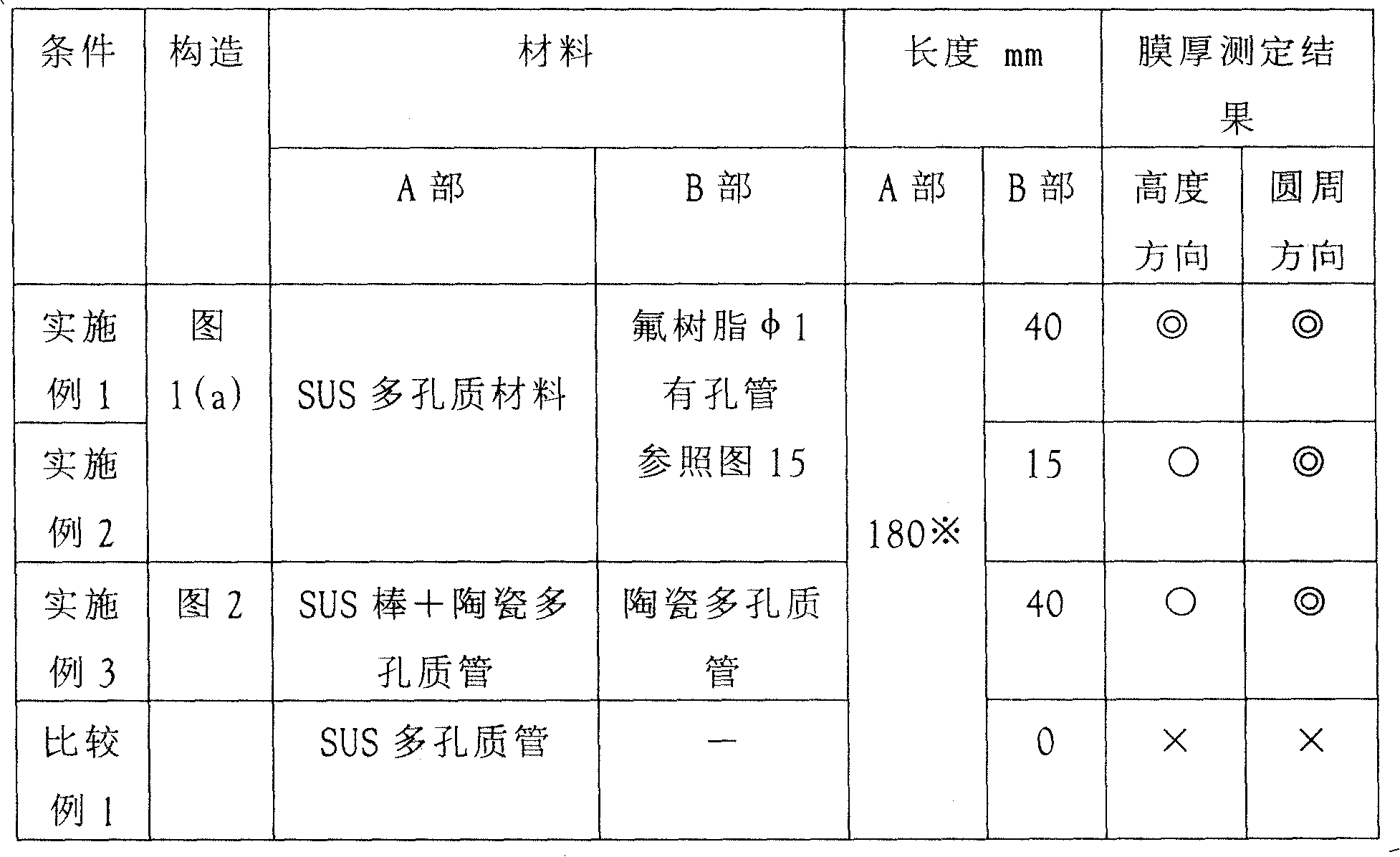
(A部:电场强度分布稳定化区域B部:前端气体诱导区域)(Part A: Electric field intensity distribution stabilization region B: Front end gas induction region)
(※:A部=180mm的情况下,到瓶子底部为止的距离=50mm)(※: In the case of part A = 180mm, the distance to the bottom of the bottle = 50mm)
结果-1result -1
根据表3和图15,在满足本发明的权利要求范围的实验条件(实施例1~3)中,通过使原料气体都能够到达瓶子的底部,瓶子底部形成比较厚的膜,同时在比较例1中看到的主体部40~100mm附近的厚度的膜厚得到改善,高度方向上的膜厚差(最大值-最小值)变小的情况得到确认。还有,通过设置前端气体诱导区域,在比较例1中看到的主体部的厚膜得到改善的理由被认为是因为,一定供应量的原料气体的一部分被引向底部,底部与主体部的流量平衡变好。According to Table 3 and Fig. 15, in satisfying the experimental condition (
结果-2result -2
根据表3和图16,在没有前端气体诱导区域的比较例1的条件下,长边部(0和180°方向)和短边部(90°和270°方向)的膜厚差大,而满足本发明的权利要求范围的实验条件(实施例1~3)中,该膜厚差得到改善的情况得到确认。According to Table 3 and Figure 16, under the conditions of Comparative Example 1 without the front end gas induction region, the film thickness difference between the long side (0 and 180° direction) and the short side (90° and 270° direction) is large, while It was confirmed that the difference in film thickness was improved in the experimental conditions (Examples 1 to 3) satisfying the scope of the claims of the present invention.
工业应用领域Industrial application
如上所述,本发明的微波等离子体处理装置及等离子体处理用气体供给构件,在将化学蒸镀膜形成于塑料容器上时,作为能够使等离子体稳定且高效率发生的等离子体处理用的装置以及气体供给管是有用的,特别适合使用于微波等离子体处理。As described above, the microwave plasma processing apparatus and the gas supply member for plasma processing of the present invention serve as an apparatus for plasma processing capable of stably and efficiently generating plasma when forming a chemical vapor deposition film on a plastic container. As well as gas supply tubes are useful, especially suitable for use in microwave plasma processing.
Claims (5)
Applications Claiming Priority (11)
| Application Number | Priority Date | Filing Date | Title |
|---|---|---|---|
| JP066911/2003 | 2003-03-12 | ||
| JP2003066911A JP4380185B2 (en) | 2003-03-12 | 2003-03-12 | Chemical plasma treatment method for inner surface of plastic bottle |
| JP2003101616A JP4232512B2 (en) | 2003-04-04 | 2003-04-04 | Microwave plasma processing apparatus and processing method |
| JP101616/2003 | 2003-04-04 | ||
| JP2003106517A JP4232519B2 (en) | 2003-04-10 | 2003-04-10 | Microwave plasma processing apparatus and processing method |
| JP106517/2003 | 2003-04-10 | ||
| JP2003130761A JP4305038B2 (en) | 2003-05-08 | 2003-05-08 | Microwave plasma processing apparatus and processing method |
| JP130761/2003 | 2003-05-08 | ||
| JP2003297272A JP4379042B2 (en) | 2003-08-21 | 2003-08-21 | Gas supply member for plasma processing used for formation of vapor deposition film by plasma CVD method, and method for forming vapor deposition film using the gas supply member |
| JP297272/2003 | 2003-08-21 | ||
| PCT/JP2004/003202 WO2004081254A1 (en) | 2003-03-12 | 2004-03-11 | Microwave plasma processing device and plasma processing gas supply member |
Related Child Applications (1)
| Application Number | Title | Priority Date | Filing Date |
|---|---|---|---|
| CN2008101859271A Division CN101435075B (en) | 2003-03-12 | 2004-03-11 | Plasma processing gas supply member |
Publications (2)
| Publication Number | Publication Date |
|---|---|
| CN1759204A CN1759204A (en) | 2006-04-12 |
| CN100453695C true CN100453695C (en) | 2009-01-21 |
Family
ID=32996468
Family Applications (2)
| Application Number | Title | Priority Date | Filing Date |
|---|---|---|---|
| CNB2004800066893A Expired - Fee Related CN100453695C (en) | 2003-03-12 | 2004-03-11 | Microwave plasma processing apparatus |
| CN2008101859271A Expired - Fee Related CN101435075B (en) | 2003-03-12 | 2004-03-11 | Plasma processing gas supply member |
Family Applications After (1)
| Application Number | Title | Priority Date | Filing Date |
|---|---|---|---|
| CN2008101859271A Expired - Fee Related CN101435075B (en) | 2003-03-12 | 2004-03-11 | Plasma processing gas supply member |
Country Status (5)
| Country | Link |
|---|---|
| US (2) | US7582845B2 (en) |
| EP (3) | EP2503023B1 (en) |
| KR (1) | KR101100963B1 (en) |
| CN (2) | CN100453695C (en) |
| WO (1) | WO2004081254A1 (en) |
Families Citing this family (17)
| Publication number | Priority date | Publication date | Assignee | Title |
|---|---|---|---|---|
| US7582845B2 (en) * | 2003-03-12 | 2009-09-01 | Toyo Seikan Kaisha Ltd. | Microwave plasma processing device and plasma processing gas supply member |
| US7892648B2 (en) * | 2005-01-21 | 2011-02-22 | International Business Machines Corporation | SiCOH dielectric material with improved toughness and improved Si-C bonding |
| JP5055834B2 (en) * | 2006-05-17 | 2012-10-24 | 東洋製罐株式会社 | Gas supply pipe for plasma processing |
| FR2903622B1 (en) * | 2006-07-17 | 2008-10-03 | Sidel Participations | DEVICE FOR DEPOSITING A COATING ON AN INTERNAL SIDE OF A CONTAINER |
| US8852685B2 (en) * | 2010-04-23 | 2014-10-07 | Lam Research Corporation | Coating method for gas delivery system |
| FI124414B (en) * | 2010-04-30 | 2014-08-29 | Beneq Oy | Outlets and apparatus for processing substrates |
| US20110272398A1 (en) * | 2010-05-07 | 2011-11-10 | Magnetic Force Corp. | Permanent Magnet Induction Heating and Levitation |
| US8597462B2 (en) * | 2010-05-21 | 2013-12-03 | Lam Research Corporation | Movable chamber liner plasma confinement screen combination for plasma processing apparatuses |
| US8278811B2 (en) * | 2010-12-30 | 2012-10-02 | General Electric Company | Device and method for circuit protection |
| CN102507003B (en) * | 2011-09-28 | 2015-02-04 | 上海华虹宏力半导体制造有限公司 | Method for detecting plasma ignition state |
| DE102012204689A1 (en) * | 2012-03-23 | 2013-09-26 | Krones Ag | Suction valve in plasma coating device |
| CA2895670A1 (en) * | 2012-09-19 | 2014-03-27 | Apjet, Inc. | Atmospheric-pressure plasma processing apparatus and method |
| CN103596351A (en) * | 2013-11-26 | 2014-02-19 | 苏州市奥普斯等离子体科技有限公司 | Plasma processing device for granular materials |
| US9812295B1 (en) * | 2016-11-15 | 2017-11-07 | Lyten, Inc. | Microwave chemical processing |
| JP2022508353A (en) | 2018-08-23 | 2022-01-19 | トランスフォーム マテリアルズ エルエルシー | Systems and methods for treating gases |
| US11633710B2 (en) | 2018-08-23 | 2023-04-25 | Transform Materials Llc | Systems and methods for processing gases |
| JP7097809B2 (en) * | 2018-12-28 | 2022-07-08 | 東京エレクトロン株式会社 | Gas introduction structure, treatment equipment and treatment method |
Citations (4)
| Publication number | Priority date | Publication date | Assignee | Title |
|---|---|---|---|---|
| JPH11172451A (en) * | 1997-12-12 | 1999-06-29 | Canon Inc | Apparatus and method for forming deposited film by plasma CVD |
| CN1280705A (en) * | 1997-09-30 | 2001-01-17 | 利乐拉瓦尔集团及财务有限公司 | Method and apparatus for treating the inside surface of plastic bottles in a plasma enhanced process |
| JP2001189308A (en) * | 1999-12-28 | 2001-07-10 | Toshiba Corp | Plasma processing apparatus and plasma processing method |
| JP2003054532A (en) * | 2000-12-25 | 2003-02-26 | Toyo Seikan Kaisha Ltd | Chemical plasma processing method for container inner surface |
Family Cites Families (9)
| Publication number | Priority date | Publication date | Assignee | Title |
|---|---|---|---|---|
| DE4318086A1 (en) * | 1993-06-01 | 1994-12-08 | Kautex Werke Gmbh | Process and device for producing a polymeric outer layer in plastic blow mouldings |
| AU2648297A (en) * | 1996-05-22 | 1997-12-09 | Tetra Laval Holdings & Finance Sa | Method and apparatus for treating inside surfaces of containers |
| AU9092298A (en) * | 1997-09-30 | 1999-04-23 | Tetra Laval Holdings & Finance Sa | Device and method for treating the inside surface of a plastic container with a narrow opening in a plasma enhanced process |
| JP4158265B2 (en) * | 1999-03-10 | 2008-10-01 | 凸版印刷株式会社 | Plastic container manufacturing method and container |
| DE10083551D2 (en) * | 1999-11-12 | 2002-12-19 | Knn Systemtechnik Gmbh | Method and device for treating and coating surfaces made of non-conductive, dielectric materials by means of microwave-excited plasmas |
| DE19963122A1 (en) * | 1999-12-24 | 2001-06-28 | Tetra Laval Holdings & Finance | Plasma chemical vapor deposition assembly has a cylindrical structure with a waveguide system to couple the microwave energy with a gas feed to coat the interior of plastics containers of all shapes and sizes without modification |
| FR2812568B1 (en) * | 2000-08-01 | 2003-08-08 | Sidel Sa | BARRIER COATING DEPOSITED BY PLASMA COMPRISING AN INTERFACE LAYER, METHOD FOR OBTAINING SUCH A COATING AND CONTAINER COATED WITH SUCH A COATING |
| JP3993971B2 (en) | 2000-08-09 | 2007-10-17 | 北海製罐株式会社 | Plastic container having gas barrier coating layer and method for producing the same |
| US7582845B2 (en) * | 2003-03-12 | 2009-09-01 | Toyo Seikan Kaisha Ltd. | Microwave plasma processing device and plasma processing gas supply member |
-
2004
- 2004-03-11 US US10/546,283 patent/US7582845B2/en not_active Expired - Fee Related
- 2004-03-11 WO PCT/JP2004/003202 patent/WO2004081254A1/en not_active Ceased
- 2004-03-11 EP EP12161825.0A patent/EP2503023B1/en not_active Expired - Lifetime
- 2004-03-11 CN CNB2004800066893A patent/CN100453695C/en not_active Expired - Fee Related
- 2004-03-11 EP EP12161819.3A patent/EP2495350B1/en not_active Expired - Lifetime
- 2004-03-11 CN CN2008101859271A patent/CN101435075B/en not_active Expired - Fee Related
- 2004-03-11 EP EP04719634.0A patent/EP1602748B1/en not_active Expired - Lifetime
- 2004-03-11 KR KR1020057016949A patent/KR101100963B1/en not_active Expired - Fee Related
-
2009
- 2009-06-12 US US12/457,497 patent/US8680424B2/en not_active Expired - Fee Related
Patent Citations (4)
| Publication number | Priority date | Publication date | Assignee | Title |
|---|---|---|---|---|
| CN1280705A (en) * | 1997-09-30 | 2001-01-17 | 利乐拉瓦尔集团及财务有限公司 | Method and apparatus for treating the inside surface of plastic bottles in a plasma enhanced process |
| JPH11172451A (en) * | 1997-12-12 | 1999-06-29 | Canon Inc | Apparatus and method for forming deposited film by plasma CVD |
| JP2001189308A (en) * | 1999-12-28 | 2001-07-10 | Toshiba Corp | Plasma processing apparatus and plasma processing method |
| JP2003054532A (en) * | 2000-12-25 | 2003-02-26 | Toyo Seikan Kaisha Ltd | Chemical plasma processing method for container inner surface |
Also Published As
| Publication number | Publication date |
|---|---|
| US8680424B2 (en) | 2014-03-25 |
| CN101435075B (en) | 2011-11-02 |
| WO2004081254A1 (en) | 2004-09-23 |
| EP1602748B1 (en) | 2014-07-09 |
| EP2503023A2 (en) | 2012-09-26 |
| US20090250444A1 (en) | 2009-10-08 |
| EP1602748A4 (en) | 2009-12-09 |
| EP2503023B1 (en) | 2016-02-24 |
| EP2495350A2 (en) | 2012-09-05 |
| US7582845B2 (en) | 2009-09-01 |
| CN1759204A (en) | 2006-04-12 |
| EP2495350B1 (en) | 2014-06-18 |
| KR20060019505A (en) | 2006-03-03 |
| EP2495350A3 (en) | 2013-01-09 |
| EP2503023A3 (en) | 2013-11-06 |
| KR101100963B1 (en) | 2011-12-29 |
| US20060289401A1 (en) | 2006-12-28 |
| CN101435075A (en) | 2009-05-20 |
| EP1602748A1 (en) | 2005-12-07 |
Similar Documents
| Publication | Publication Date | Title |
|---|---|---|
| CN100453695C (en) | Microwave plasma processing apparatus | |
| TWI262748B (en) | Method of treatment with a microwave plasma | |
| CN100447297C (en) | Microwave plasma treatment method | |
| JP4380185B2 (en) | Chemical plasma treatment method for inner surface of plastic bottle | |
| JP4379042B2 (en) | Gas supply member for plasma processing used for formation of vapor deposition film by plasma CVD method, and method for forming vapor deposition film using the gas supply member | |
| JP4254320B2 (en) | Microwave plasma processing apparatus and processing method | |
| JP4305038B2 (en) | Microwave plasma processing apparatus and processing method | |
| JP4232519B2 (en) | Microwave plasma processing apparatus and processing method | |
| JP4232512B2 (en) | Microwave plasma processing apparatus and processing method | |
| JP2006335379A (en) | Synthetic-resin-made container with coat, method and apparatus for forming coat on synthetic-resin-made container | |
| JP4873037B2 (en) | Non-pressure resistant plastic container |
Legal Events
| Date | Code | Title | Description |
|---|---|---|---|
| C06 | Publication | ||
| PB01 | Publication | ||
| C10 | Entry into substantive examination | ||
| SE01 | Entry into force of request for substantive examination | ||
| C14 | Grant of patent or utility model | ||
| GR01 | Patent grant | ||
| CF01 | Termination of patent right due to non-payment of annual fee | ||
| CF01 | Termination of patent right due to non-payment of annual fee |
Granted publication date: 20090121 Termination date: 20210311 |