CN100437434C - Cotrol starting circuit and method of multiple IDE device - Google Patents
Cotrol starting circuit and method of multiple IDE device Download PDFInfo
- Publication number
- CN100437434C CN100437434C CNB021345422A CN02134542A CN100437434C CN 100437434 C CN100437434 C CN 100437434C CN B021345422 A CNB021345422 A CN B021345422A CN 02134542 A CN02134542 A CN 02134542A CN 100437434 C CN100437434 C CN 100437434C
- Authority
- CN
- China
- Prior art keywords
- ide
- devices
- controller
- ide devices
- several
- Prior art date
- Legal status (The legal status is an assumption and is not a legal conclusion. Google has not performed a legal analysis and makes no representation as to the accuracy of the status listed.)
- Expired - Fee Related
Links
Images


Landscapes
- Power Sources (AREA)
Abstract
一种控制IDE装置的启动电路及方法,其中该电路包括主机,若干IDE装置,若干相应于IDE装置而设置的快速开关及若干可与主机进行信息交换并能控制IDE装置的控制器。所述主机的IDE接口设有用以指定ID数值的ID指示接脚及一ID设置接脚。通过控制ID设置接脚的电压,控制器将受主机控制而进入获取ID数值状态,再根据ID数值依次延时开启快速开关,以使电能依次传送至相应IDE装置,从而使IDE装置依次启动,避免同时启动时造成过大的功率消耗。
A starting circuit and method for controlling IDE devices, wherein the circuit includes a host, several IDE devices, several quick switches corresponding to the IDE devices, and several controllers capable of exchanging information with the host and controlling the IDE devices. The IDE interface of the host computer is provided with an ID indicating pin for specifying an ID value and an ID setting pin. By controlling the voltage of the ID setting pin, the controller will be controlled by the host to enter the state of obtaining the ID value, and then turn on the fast switch with a delay according to the ID value, so that the power can be transmitted to the corresponding IDE devices in sequence, so that the IDE devices are started in sequence. Avoid excessive power consumption when starting at the same time.
Description
【技术领域】【Technical field】
本发明关于一种控制多IDE装置的启动电路及方法,尤其关于一种控制多IDE装置在计算机启动时间内依次启动的电路及方法。The present invention relates to a start-up circuit and method for controlling multiple IDE devices, in particular to a circuit and method for controlling start-up of multiple IDE devices in sequence within the computer start-up time.
【背景技术】【Background technique】
随着计算机技术的发展,对内存容量的要求越来越高。为提升内存容量,计算机系统通常会被附加上具有高存取容量之永久性外部记忆装置。而IDE硬盘装置(HDD)则是目前应用最普遍的一种外部记忆装置。With the development of computer technology, the requirements for memory capacity are getting higher and higher. In order to increase the memory capacity, the computer system is usually equipped with a non-volatile external memory device with high access capacity. The IDE hard disk device (HDD) is currently the most widely used external memory device.
IDE硬盘装置通常包括存取介质、读/写磁头、用来旋转存取介质的马达、及电路板,其中电路板设有介面接口用以将IDE硬盘装置连接至计算机的硬盘控制板上,而IDE接口则是将连接电子装置至计算机上的一种常用标准接口,凡符合IDE标准的IDE硬盘装置即称为IDE硬盘装置(IDE HDD)。IDE标准允许两个IDE硬盘装置通过同一IDE接口连接至一硬盘控制板,其中之一IDE硬盘装置由计算机系统的控制信号指定为主IDE硬盘装置,另一则为从属IDE硬盘装置。The IDE hard disk device usually includes an access medium, a read/write head, a motor for rotating the access medium, and a circuit board, wherein the circuit board is provided with an interface interface for connecting the IDE hard disk device to the hard disk control board of the computer, and The IDE interface is a commonly used standard interface for connecting electronic devices to computers. All IDE hard disk devices that meet the IDE standard are called IDE hard disk devices (IDE HDD). The IDE standard allows two IDE hard disk devices to be connected to a hard disk control board through the same IDE interface. One of the IDE hard disk devices is designated as the master IDE hard disk device by the control signal of the computer system, and the other is the slave IDE hard disk device.
在仅连接两个IDE硬盘装置的情况下,当计算机系统启动过程中,电源接通的同时,IDE硬盘装置便在马达的驱动下立即开始运转。在初始的这段时间内,每一IDE硬盘装置的瞬时峰值电流可达2A。当马达旋转趋于稳定后,IDE硬盘装置所消耗的电流将降至为较低的平均值。计算机系统中使用较少的IDE硬盘装置,其启动时的功率消耗对电源供应器的影响尚不明显。When only two IDE hard disk devices are connected, when the computer system starts up, the IDE hard disk device starts to run immediately under the drive of the motor when the power is turned on. During the initial period, the instantaneous peak current of each IDE hard disk device can reach 2A. When the motor rotation becomes stable, the current consumed by the IDE hard disk device will drop to a lower average value. There are few IDE hard disk devices used in computer systems, and the influence of power consumption on the power supply during startup is not obvious.
然而,在要求较大存取容量的场合,如网络系统,需要附加较多的IDE硬盘装置。例如,若连接有八个IDE硬盘装置,同时启动运转时,则瞬时峰值电流将高达16A,普通电源供应器无法承受如此大功率消耗,极易被烧毁,而换用特殊电源供应器,则成本将会增加。However, in occasions requiring larger access capacity, such as network systems, more IDE hard disk devices need to be added. For example, if there are eight IDE hard disk devices connected, when they start running at the same time, the instantaneous peak current will be as high as 16A. Ordinary power supplies cannot withstand such a large power consumption and are easily burned. will increase.
所以,需要提供一种控制多IDE装置的启动电路及方法,以减小其在启动时的功率消耗,确保整个系统的正常工作。Therefore, it is necessary to provide a startup circuit and method for controlling multiple IDE devices, so as to reduce the power consumption during startup and ensure the normal operation of the entire system.
【发明内容】【Content of invention】
本发明之一目的在于提供一种控制多IDE装置的启动电路及方法,可降低多IDE装置启动时的功率消耗。One object of the present invention is to provide a startup circuit and method for controlling multiple IDE devices, which can reduce the power consumption when the multiple IDE devices start up.
本发明之另一目的在于提供一种控制多IDE装置的启动电路及方法,系统不需换用特殊电源供应器,以降低成本。Another object of the present invention is to provide a start-up circuit and method for controlling multiple IDE devices. The system does not need to replace a special power supply to reduce costs.
为实现上述目的,本发明提供一种控制IDE装置的启动电路及方法,其中该电路包括主机,若干IDE装置,若干相应于IDE装置而设置的快速开关及若干可与主机进行信息交换并能控制IDE装置的控制器。所述主机的IDE接口设有用以指定ID数值的ID指示接脚及一ID设置接脚。通过控制ID设置接脚的电压,控制器将受主机控制而进入获取ID数值状态,再根据ID数值依次延时开启快速开关,以使电能依次传送至相应IDE装置,从而使IDE装置依次启动。In order to achieve the above object, the present invention provides a startup circuit and method for controlling IDE devices, wherein the circuit includes a host, several IDE devices, some fast switches set corresponding to the IDE devices, and several capable of exchanging information with the host and controlling Controller for IDE devices. The IDE interface of the host is provided with an ID indicating pin for specifying an ID value and an ID setting pin. By controlling the voltage of the ID setting pin, the controller will be controlled by the host to enter the state of obtaining the ID value, and then turn on the fast switch with a delay according to the ID value, so that the power is sequentially transmitted to the corresponding IDE devices, so that the IDE devices are started in sequence.
与现有技术相比,本发明提供的控制多IDE装置的启动电路及方法,通过分配ID数值,系统自动延时,使得各对IDE硬盘装置依次启动,避免其同时启动时产生过大的瞬时峰值电流,烧毁电源供应器,从而也不需换用成本较高的特殊电源供应器。Compared with the prior art, the start-up circuit and method for controlling multiple IDE devices provided by the present invention can automatically delay the system by assigning ID values, so that each pair of IDE hard disk devices starts up sequentially, avoiding excessive instantaneous The peak current will burn the power supply, so there is no need to replace it with a high-cost special power supply.
【附图说明】【Description of drawings】
图1为本发明所提供的控制多IDE硬盘装置的启动电路示意图。FIG. 1 is a schematic diagram of a start-up circuit for controlling multiple IDE hard disk devices provided by the present invention.
图2为本发明所提供的控制一对IDE硬盘装置的启动电路示意图。FIG. 2 is a schematic diagram of a start-up circuit for controlling a pair of IDE hard disk devices provided by the present invention.
图3为本发明所提供的控制多IDE硬盘装置的流程图。FIG. 3 is a flow chart of controlling multiple IDE hard disk devices provided by the present invention.
图4为本发明另一实施例的启动电路示意图。FIG. 4 is a schematic diagram of a start-up circuit according to another embodiment of the present invention.
图5为本发明另一实施例的流程图。Fig. 5 is a flowchart of another embodiment of the present invention.
【具体实施方式】【Detailed ways】
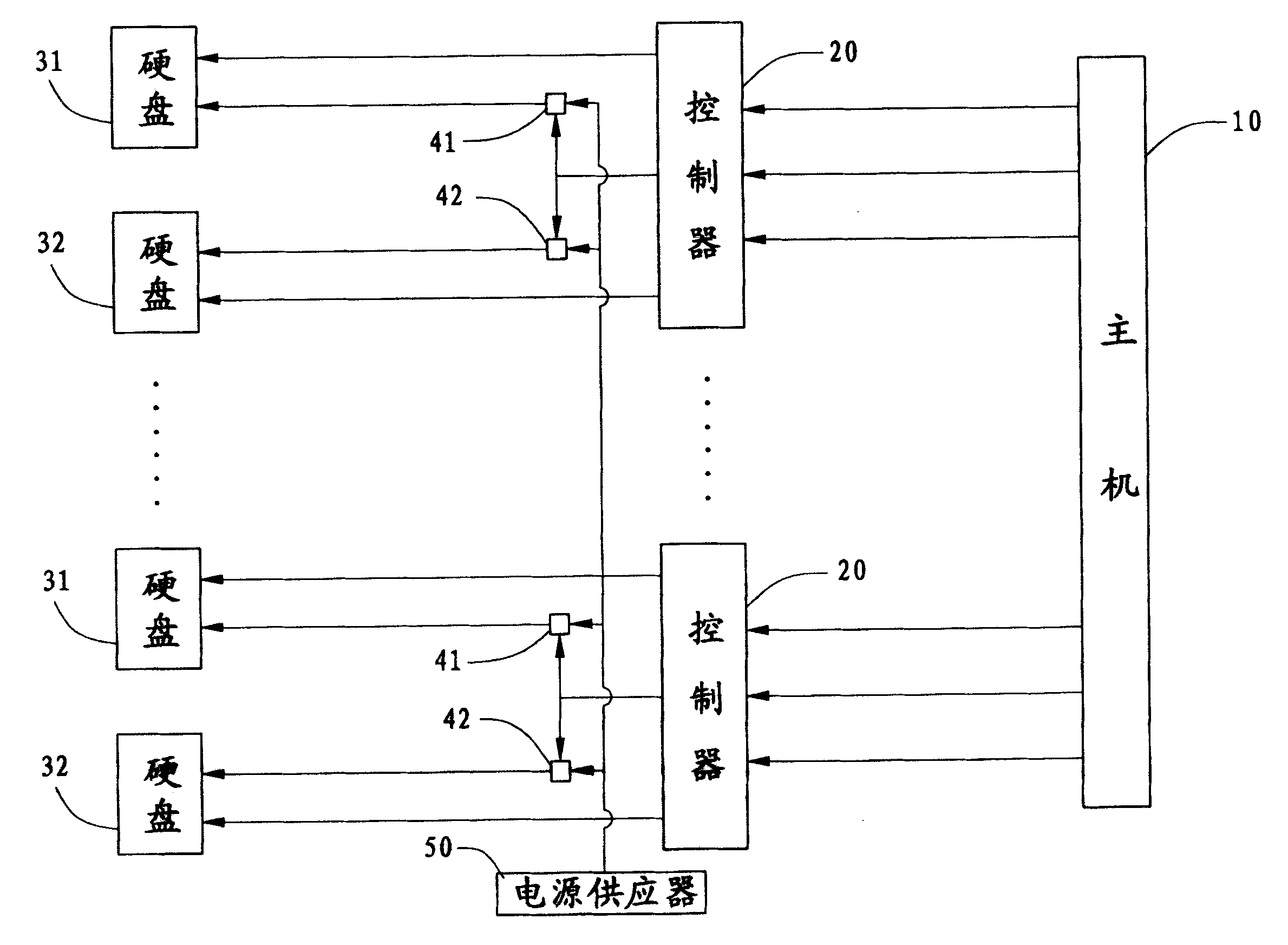
请参照图1所示,为本发明所提供的控制多IDE装置的启动电路示意图。本实施例所采用的IDE装置为IDE硬盘装置,电路包括主机10、四个控制器20、四对IDE硬盘装置31、32(每两个为一对)及与之相应设置的四对第一、第二快速开关41、42。其中每一控制器分别控制一对IDE硬盘装置31、32。另外,该电路还提供一电源供应器50,可为IDE硬盘装置31、32的启动提供电能。其中所述主机10设有IDE接口(未图示),用来连接IDE硬盘装置,因IDE装置与IDE接口的连接方式已为本领域普通技术人员熟知,且与本发明较不相关,所以此处省略对其的描述。Please refer to FIG. 1 , which is a schematic diagram of a start-up circuit for controlling multiple IDE devices provided by the present invention. The IDE device used in this embodiment is an IDE hard disk device, and the circuit includes a
为避免重复,以下仅选取控制其中两个IDE硬盘装置启动的电路作详细说明。In order to avoid repetition, only the circuits controlling the startup of the two IDE hard disk devices will be selected for detailed description below.
请参照图2所示,主机10上的IDE接口提供三个未使用的接脚作为ID指示接脚MON、SON及控制接脚DIDSET,其中ID指示接脚MON与SON用来指定控制器20所占用的IDE接口的ID数值。在控制器20上跳线(Jumper)或固件(Firmware)的控制下,通过主机IDE接口上的ID指示接脚MON与SON高、低电压的设置,可指定每一控制器20所占用的IDE接口的ID数值。本实施方式可设置四个IDE接口的ID数值,也可根据实际使用到的硬盘数量设置1-3个IDE接口的ID数值。DIDSET/的意义在于若其为低电压时,则表示主机10此时指令控制器20进入获取ID数值的状态。当然,也可设置DIDSET/为高电压时表示主机10此时指令控制器20进入获取ID数值的状态。Please refer to FIG. 2, the IDE interface on the
控制器20用以控制两IDE硬盘装置31、32,本实施例中IDE硬盘装置31被指定为主IDE硬盘装置,IDE硬盘装置32被指定为从属IDE硬盘装置。控制器20设有HD_RESET1/、HD_RESET2/接脚分别与主IDE硬盘装置31的HD_RESET/、从属IDE硬盘装置32的HD_RESET/相连,以控制该二IDE硬盘装置的重新启动。两个IDE硬盘装置31、32上还分别设有PWR1、PWR2接脚,接收电源供应器50传送的电能。The
本电路的第一、第二快速开关41、42受控制器20的QS接脚控制而开启或关闭,当其开启时,电源供应器50提供的电能便分别传送至IDE硬盘装置31、32的PWR1、PWR2接脚。The first and second
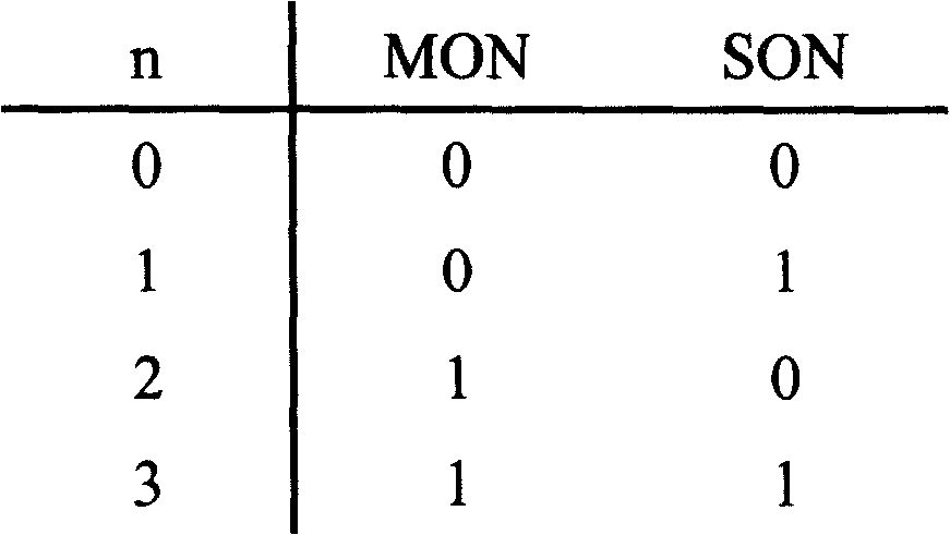
请参照图3所示,为上述电路的工作流程。步骤60为初始动作,系统侦测DIDSET/是否为低电压,若为低电压,则电路开始工作,将执行下一步骤61,从主机10获取ID数值,并记为n,n的取值参见下表(假设共有4个IDE接口,“0”、“1”分别代表MON、SON的高低电压)。Please refer to FIG. 3 , which is the workflow of the above circuit.
当获取一特定的ID数值n后,控制器20将执行步骤62,控制ID数值被分配为n的IDE硬盘装置延迟启动(m*n)秒。在连接有4个IDE接口,即4对IDE硬盘装置(1主IDE硬盘装置与1从属IDE硬盘装置为1对)的情况下,n取值从0到3,则每一IDE接口连接的一对IDE硬盘装置,启动时间依次间隔m秒。步骤63系由控制器20的QS控制,相应快速开关41、42同时开启,使得电源供应器50开始为IDE硬盘装置31、32供电,IDE硬盘装置31、32同时启动。按上述步骤,每对IDE硬盘装置31、32可分别完成启动。After obtaining a specific ID value n, the
图4为本发明另一实施例的电路示意图,其中控制器20设有QS1、QS2接脚,分别控制第一、第二快速开关41、42的开启及关闭。相应地,图5为图4所示电路的工作流程图。其中,在执行步骤61获取ID数值n后,进入步骤62’,系统延时(2m*n)秒,即每一对IDE硬盘装置的启动时间依次间隔2m秒。然后执行步骤63’,由控制器20的QS1、QS2分别控制,以任意先后顺序开启第一、第二快速开关41、42。当其中之一快速开关(例如41)先开启后,另一快速开关(例如42)将延迟m秒开启,电源供应器50将以先后间隔m秒分别为二IDE硬盘装置31、32供电,而该二IDE硬盘装置31、32则以先后间隔m秒分别启动。FIG. 4 is a schematic circuit diagram of another embodiment of the present invention, wherein the
Claims (10)
Priority Applications (1)
| Application Number | Priority Date | Filing Date | Title |
|---|---|---|---|
| CNB021345422A CN100437434C (en) | 2002-08-07 | 2002-08-07 | Cotrol starting circuit and method of multiple IDE device |
Applications Claiming Priority (1)
| Application Number | Priority Date | Filing Date | Title |
|---|---|---|---|
| CNB021345422A CN100437434C (en) | 2002-08-07 | 2002-08-07 | Cotrol starting circuit and method of multiple IDE device |
Publications (2)
| Publication Number | Publication Date |
|---|---|
| CN1474251A CN1474251A (en) | 2004-02-11 |
| CN100437434C true CN100437434C (en) | 2008-11-26 |
Family
ID=34145842
Family Applications (1)
| Application Number | Title | Priority Date | Filing Date |
|---|---|---|---|
| CNB021345422A Expired - Fee Related CN100437434C (en) | 2002-08-07 | 2002-08-07 | Cotrol starting circuit and method of multiple IDE device |
Country Status (1)
| Country | Link |
|---|---|
| CN (1) | CN100437434C (en) |
Families Citing this family (3)
| Publication number | Priority date | Publication date | Assignee | Title |
|---|---|---|---|---|
| CN102314380A (en) * | 2010-07-02 | 2012-01-11 | 鸿富锦精密工业(深圳)有限公司 | Multi-hardware start control system and method |
| CN103065690A (en) * | 2011-10-19 | 2013-04-24 | 鸿富锦精密工业(深圳)有限公司 | System and method for reducing starting current of storage system |
| CN106656519A (en) * | 2016-11-15 | 2017-05-10 | 迈普通信技术股份有限公司 | Starting method and device for communication device |
Citations (3)
| Publication number | Priority date | Publication date | Assignee | Title |
|---|---|---|---|---|
| CN2192911Y (en) * | 1994-03-11 | 1995-03-22 | 康克军 | Selector for computer supporting multi-set hardware (multiple operation system) |
| DE19841275A1 (en) * | 1998-09-09 | 2000-03-16 | Wolfgang Martin | Hardware-based boot manager for switching among bootable storage systems has switch for connecting selected storage unit |
| CA2285862A1 (en) * | 1999-10-12 | 2001-04-12 | Seung-Wook Park | Multiple boot drive selector |
-
2002
- 2002-08-07 CN CNB021345422A patent/CN100437434C/en not_active Expired - Fee Related
Patent Citations (3)
| Publication number | Priority date | Publication date | Assignee | Title |
|---|---|---|---|---|
| CN2192911Y (en) * | 1994-03-11 | 1995-03-22 | 康克军 | Selector for computer supporting multi-set hardware (multiple operation system) |
| DE19841275A1 (en) * | 1998-09-09 | 2000-03-16 | Wolfgang Martin | Hardware-based boot manager for switching among bootable storage systems has switch for connecting selected storage unit |
| CA2285862A1 (en) * | 1999-10-12 | 2001-04-12 | Seung-Wook Park | Multiple boot drive selector |
Also Published As
| Publication number | Publication date |
|---|---|
| CN1474251A (en) | 2004-02-11 |
Similar Documents
| Publication | Publication Date | Title |
|---|---|---|
| JP4164073B2 (en) | Computer with multi-function power button and related method | |
| CN103136012B (en) | Computer system and update method of basic input-output system thereof | |
| CN103870425A (en) | Bridge device, production system and method for automatic production of storage devices | |
| JP2009271637A (en) | Storage device and its drive startup method | |
| CN105867949A (en) | Online BIOS (basic input/output system) refreshing method for multi-node server | |
| CN101424971A (en) | Information processing apparatus and control method | |
| TWI220978B (en) | A controlling circuit and method for powering on a plurality of IDE devices | |
| KR20180085192A (en) | System including hot plug module and memory module | |
| TW200923784A (en) | Electronic device and method for resuming from suspend-to-ram state thereof | |
| TWI489296B (en) | Computer | |
| CN103593319A (en) | Serial port application method for supporting hot plugging and identifying external device automatically | |
| CN100437434C (en) | Cotrol starting circuit and method of multiple IDE device | |
| US20250077100A1 (en) | Control method, storage apparatus, and electronic device | |
| WO2025214078A1 (en) | Computing device and control method | |
| CN116643640B (en) | Step-by-step power-up method, device, equipment and storage medium of server system | |
| CN101582014B (en) | Control device and method of external storage device | |
| CN119396748A (en) | Device management method, system, computer program product, electronic device and medium | |
| CN114020219B (en) | Power backup device and power backup method and medium thereof | |
| CN201015041Y (en) | BIOS chip extended device | |
| JP2001337789A (en) | Disk subsystem | |
| CN117251103A (en) | Storage device and method for entering deep low-power state with low latency | |
| JP2001350548A (en) | Power control circuit of external storage device | |
| CN1220928C (en) | Circuit and method for ID of specific IDE device | |
| CN112783806B (en) | Control device and method under SSD data storage | |
| CN221551144U (en) | A computing device |
Legal Events
| Date | Code | Title | Description |
|---|---|---|---|
| C06 | Publication | ||
| PB01 | Publication | ||
| C10 | Entry into substantive examination | ||
| SE01 | Entry into force of request for substantive examination | ||
| C14 | Grant of patent or utility model | ||
| GR01 | Patent grant | ||
| CF01 | Termination of patent right due to non-payment of annual fee |
Granted publication date: 20081126 Termination date: 20140807 |
|
| EXPY | Termination of patent right or utility model |