CN100433691C - Routing method of virtual special network - Google Patents
Routing method of virtual special network Download PDFInfo
- Publication number
- CN100433691C CN100433691C CNB2005101174980A CN200510117498A CN100433691C CN 100433691 C CN100433691 C CN 100433691C CN B2005101174980 A CNB2005101174980 A CN B2005101174980A CN 200510117498 A CN200510117498 A CN 200510117498A CN 100433691 C CN100433691 C CN 100433691C
- Authority
- CN
- China
- Prior art keywords
- vpn
- destination
- routing information
- address
- ipv4
- Prior art date
- Legal status (The legal status is an assumption and is not a legal conclusion. Google has not performed a legal analysis and makes no representation as to the accuracy of the status listed.)
- Expired - Fee Related
Links
Images


Landscapes
- Data Exchanges In Wide-Area Networks (AREA)
Abstract
本发明公开了一种虚拟专用网络的路由方法,应用于基于IPv6骨干网络和IPv4用户网络的通信系统中,该方法包括:IPv4用户网络中目的VPN站点通过IPv6骨干网络将目的站点的路由信息发送给IPv4用户网络中的源VPN站点,并且在源VPN站点的出口提供商边缘设备PE和目的VPN站点的入口PE之间建立隧道;源VPN站点利用目的VPN站点的路由信息和隧道向目的VPN站点发送业务流。本发明可以有效的完成在向IPv6的过渡过程中基于IPv6骨干网络的SP向基于IPv4的用户提供VPN服务的问题。而且,本发明不需要升级硬件,仅需要对PE设备的软件进行改进,配置方式简单、易行,并且具有良好的可扩展性。
The invention discloses a routing method of a virtual private network, which is applied to a communication system based on an IPv6 backbone network and an IPv4 user network. The method includes: the destination VPN site in the IPv4 user network sends the routing information of the destination site through the IPv6 backbone network To the source VPN site in the IPv4 user network, and establish a tunnel between the egress provider edge device PE of the source VPN site and the ingress PE of the destination VPN site; the source VPN site uses the routing information of the destination VPN site and the tunnel to the destination VPN site Send traffic. The invention can effectively complete the problem that the SP based on the IPv6 backbone network provides VPN service to the users based on IPv4 in the transition process to IPv6. Moreover, the present invention does not need to upgrade the hardware, but only needs to improve the software of the PE equipment, the configuration mode is simple, easy to implement, and has good scalability.
Description
技术领域 technical field
本发明涉及虚拟专用网(VPN)技术领域,特别是指一种基于IPv6骨干网络和IPv4用户网络的VPN的路由方法。The invention relates to the technical field of a virtual private network (VPN), in particular to a VPN routing method based on an IPv6 backbone network and an IPv4 user network.
背景技术 Background technique
多协议标签交换(MPLS)是一种利用绑定在IP包中的标签通过网络进行数据转发的技术。通常将IP包封装为MPLS报文,MPLS报文首部携带根据等价转发类分配的标签,在MPLS路由器进行标签操作,并根据标签将报文从相应的接口转发出去,逐级转发至目的地。Multiprotocol Label Switching (MPLS) is a technology that utilizes labels bound in IP packets to forward data over a network. IP packets are usually encapsulated into MPLS packets, and the MPLS packet headers carry labels assigned according to the equivalent forwarding class. Label operations are performed on the MPLS router, and the packets are forwarded from the corresponding interface according to the labels, and forwarded to the destination step by step. .
BGP/MPLS VPN是指在PE路由器上为不同的VPN用户建立不同的虚拟路由转发表,形成MPLS转发表,利用BGP4+协议的多协议扩展的承载能力通告VPN路由,进而在VPN用户间实现路由隔离和通告,转发业务流,实现VPN服务。BGP/MPLS VPN refers to the establishment of different virtual routing forwarding tables for different VPN users on PE routers, forming MPLS forwarding tables, and using the multi-protocol extension of the BGP4+ protocol to advertise VPN routes, thereby realizing route isolation between VPN users and notifications, forwarding business flows, and implementing VPN services.
RFC2547bis提出了基于纯IPv4域的BGP/MPLS VPN解决方案,该方案目前已经相当成熟并被广泛应用于实际网络中。随着IPv6网络的出现,越来越多厂商提供对IPv6的支持,已经提出了基于纯IPv6域的BGP/MPLSVPN解决方案和基于IPv4骨干网、IPv6用户的BGP/MPLS VPN解决方案。但在IPv4向IPv6过渡过程的后期,会出现IPv6骨干网、IPv4用户网络,而目前无法实现IPv4用户网络、IPv6骨干网结构下的BGP/MPLS VPN业务。RFC2547bis proposes a BGP/MPLS VPN solution based on pure IPv4 domain, which is quite mature and widely used in actual networks. With the emergence of IPv6 networks, more and more manufacturers provide support for IPv6. BGP/MPLS VPN solutions based on pure IPv6 domains and BGP/MPLS VPN solutions based on IPv4 backbone networks and IPv6 users have been proposed. However, in the later stage of the transition from IPv4 to IPv6, IPv6 backbone networks and IPv4 user networks will appear, but BGP/MPLS VPN services under the structure of IPv4 user networks and IPv6 backbone networks cannot be realized at present.
下面参见图1具体说明基于IPv4骨干网、IPv6用户的BGP/MPLS VPN解决方案。Refer to Figure 1 below to illustrate the BGP/MPLS VPN solution based on IPv4 backbone network and IPv6 users.
如图1所示,站点1和站点3同属于VPN1,站点2和站点4同属于VPN2,用户站点都基于IPv6,MPLS骨干网络基于IPv4。下面以在VPN2中站点4的VPN路由通告到站点2,站点2向站点4发送VPN业务流为例,对每个VPN中两个VPN站点之间的通信方法进行说明。As shown in Figure 1, Site 1 and Site 3 belong to VPN1, Site 2 and Site 4 belong to VPN2, user sites are based on IPv6, and the MPLS backbone network is based on IPv4. The following describes the communication method between two VPN sites in each VPN by taking the VPN route of site 4 advertised to site 2 in VPN2 and site 2 sending VPN traffic to site 4 as an example.
需要说明的是,在VPN2中,如果要使VPN站点2和VPN站点4之间建立通信,必须首先要互相学习到能够到达对方站点的VPN路由。由于VPN站点2和VPN站点4属于IPv6站点,骨干网为基于IPv4的MPLS网络,所以必须在IPv4MPLS骨干网络中传递IPv6VPN路由信息。目前是利用BGP多协议可达属性在IPv4 MPLS骨干网络平台上发布IPv6 VPN路由信息。It should be noted that, in VPN2, if communication between VPN site 2 and VPN site 4 is to be established, they must learn each other's VPN route to reach the other site. Since VPN site 2 and VPN site 4 belong to IPv6 sites, and the backbone network is an IPv4-based MPLS network, IPv6 VPN routing information must be transmitted in the IPv4 MPLS backbone network. Currently, the BGP multi-protocol reachability attribute is used to publish IPv6 VPN routing information on the IPv4 MPLS backbone network platform.
参见图1所示,CE4,即VPN站点4为目的VPN站点、CE2,即VPN站点2为源VPN站点;PE2为出口PE,PE1为入口PE。路由信息的发布属于控制流信息,具体如下:Referring to Fig. 1, CE4, that is, VPN site 4 is the destination VPN site, CE2, that is, VPN site 2 is the source VPN site; PE2 is the egress PE, and PE1 is the ingress PE. The release of routing information belongs to control flow information, as follows:
(1)CE4向PE2发布站点4内部IPv6路由3ffe:3210::/32。具体方式可以采用静态路由、OSPF、RIP等路由协议。(1) CE4 advertises the internal IPv6 route 3ffe:3210::/32 of site 4 to PE2. The specific way can be static routing, OSPF, RIP and other routing protocols.
(2)PE2接收该路由后,将其添加到VPN2对应的IPv6虚拟路由转发表VRF中,并为该路由分配标签。(2) After receiving the route, PE2 adds it to the IPv6 virtual route forwarding table VRF corresponding to VPN2, and assigns a label to the route.
这里,该VRF记录了所有VPN2的VPN路由条目。VPN路由是指一个BGP的UPDATE数据包,内部包括路由标识RD和路由目标RT、VPN目的地址以及下一跳地址等,并为该路由分配标签。Here, the VRF records all VPN routing entries of VPN2. A VPN route refers to a BGP UPDATE packet, which includes a routing identifier RD, a routing target RT, a VPN destination address, and a next-hop address, etc., and assigns a label to the route.
(3)PE2通过IBGP将该IPv6标签路由通告给PE1,多协议可达属性中目的字段为3ffe:3210::/32对应的IPv6VPN地址,下个中继字段为PE1的IPv4地址映射的IPv6 VPN地址。(3) PE2 advertises the IPv6 label route to PE1 through IBGP, the destination field in the multi-protocol reachability attribute is the IPv6 VPN address corresponding to 3ffe:3210::/32, and the next relay field is the IPv6 VPN mapped to the IPv4 address of PE1 address.
(4)PE1接收该路由,将其添加到VPN2对应的IPv6虚拟路由转发表VRF中,下个中继为PE2,并通过静态路由、OSPF、RIP等方法向CE2发布该路由。(4) PE1 receives the route, adds it to the IPv6 virtual routing forwarding table VRF corresponding to VPN2, the next relay is PE2, and advertises the route to CE2 through static routing, OSPF, RIP and other methods.
二、站点2向站点4发送的VPN业务属于数据流信息,具体如下:2. The VPN service sent by site 2 to site 4 belongs to data flow information, as follows:
(1)站点2将IPv6数据包发送至PE1。(1) Site 2 sends the IPv6 data packet to PE1.
(2)PE1查询对应的MPLS转发表和VRF,为IPv6数据包压入二级标签,栈底标签是PE2为站点4中IPv6 VPN路由分配的标签,栈顶标签为PE1到PE2的LSP标签。(2) PE1 queries the corresponding MPLS forwarding table and VRF, and pushes the secondary label for the IPv6 data packet. The bottom label of the stack is the label allocated by PE2 for the IPv6 VPN route in site 4, and the top label is the LSP label from PE1 to PE2.
(3)经过PE1到PE2的LSP,该MPLS报文逐级转发至PE2。(3) Through the LSP from PE1 to PE2, the MPLS message is forwarded to PE2 level by level.
(4)PE2根据栈底标签将MPLS报文还原为IPv6数据包,并转发至站点4。(4) PE2 restores the MPLS message to an IPv6 data packet according to the bottom label of the stack, and forwards it to site 4.
现有技术中上述方案解决了骨干网为IPv4或IPv6单自治系统,VPN用户站点为IPv6网络下VPN站点间通信问题,当IPv6取代IPv4后,会出现IPv6骨干网、IPv4用户网络,目前无法实现IPv4用户网络、IPv6骨干网结构下的BGP/MPLS VPN业务。In the prior art, the above solution solves the problem of communication between VPN sites where the backbone network is an IPv4 or IPv6 single autonomous system, and the VPN user site is an IPv6 network. When IPv6 replaces IPv4, there will be an IPv6 backbone network and an IPv4 user network, which cannot be realized at present BGP/MPLS VPN service under IPv4 user network and IPv6 backbone network structure.
发明内容 Contents of the invention
有鉴于此,本发明的目的是提供一种基于IPv6骨干网络和IPv4用户网络的VPN的路由方法,使其能在IPv6骨干网和IPv4用户组成的网络结构中提供VPN服务。In view of this, the object of the present invention is to provide a VPN routing method based on IPv6 backbone network and IPv4 user network, so that it can provide VPN service in the network structure composed of IPv6 backbone network and IPv4 user network.
本发明提供的一种基于IPv6骨干网络和IPv4用户网络的VPN的路由方法是这样实现的:A kind of routing method based on the VPN of IPv6 backbone network and IPv4 user network provided by the present invention is realized like this:
一种虚拟专用网络中的路由方法,应用于基于IPv6骨干网络和IPv4用户网络的通信系统中,每个VPN对应一个兼容虚拟路由转发表VRF,兼容VRF支持IPv4兼容IPv6地址,每个兼容VRF对应一个路由目标属性,该方法包括以下步骤:A routing method in a virtual private network, applied in a communication system based on an IPv6 backbone network and an IPv4 user network, each VPN corresponds to a compatible virtual routing and forwarding table VRF, the compatible VRF supports IPv4 compatible IPv6 addresses, and each compatible VRF corresponds to A route target attribute, the method includes the following steps:
a.IPv4用户网络中目的VPN站点向出口提供商边缘设备PE发送目的VPN站点的、地址为IPv4地址格式的路由信息;出口PE根据目的VPN对应的兼容VRF,将该路由信息转换为地址为IPv4兼容IPv6地址格式的路由信息,并通过IPv6骨干网络发送至入口PE;入口PE根据目的VPN对应的兼容VRF,将接收到的地址为IPv4兼容IPv6地址格式的路由信息转换为地址为IPv4地址格式的路由信息后发送至IPv4用户网络中的源VPN站点;a. The destination VPN site in the IPv4 user network sends the routing information of the destination VPN site in the IPv4 address format to the edge device PE of the egress provider; the egress PE converts the routing information into an IPv4 address according to the compatible VRF corresponding to the destination VPN The routing information in compatible IPv6 address format is sent to the ingress PE through the IPv6 backbone network; the ingress PE converts the received routing information in the IPv4-compatible IPv6 address format into the address in the IPv4 address format according to the compatible VRF corresponding to the destination VPN. Send the routing information to the source VPN site in the IPv4 user network;
并且在源VPN站点的入口PE和目的VPN站点的出口PE之间建立隧道;And a tunnel is established between the ingress PE of the source VPN site and the egress PE of the destination VPN site;
b.源VPN站点利用目的VPN站点的路由信息和隧道向目的VPN站点发送业务流。b. The source VPN site uses the routing information and tunnel of the destination VPN site to send the service flow to the destination VPN site.
所述隧道为标签交换路径LSP。The tunnel is a label switching path LSP.
所述隧道是所述目的VPN站点通过IPv6骨干网络将目的站点的VPN路由信息发送给IPv4用户网络中的源站点之前或之后建立。The tunnel is established before or after the destination VPN site sends the VPN routing information of the destination site to the source site in the IPv4 user network through the IPv6 backbone network.
所述LSP利用LDP或RSVP建立。The LSP is established using LDP or RSVP.
步骤a中,出口PE将转换地址格式后的路由信息通过IPv6骨干网络发送至入口PE的步骤包括:In step a, the steps for the egress PE to send the route information after the converted address format to the ingress PE through the IPv6 backbone network include:
a11、出口PE将该VPN的兼容VRF中目的地址设置为该路由信息中的IPv4地址,下一跳地址设置为目的VPN站点,并且为该路由信息分配一个LSP,并利用该LSP修改自身保存的MPLS标签转发表;a11. The egress PE sets the destination address in the compatible VRF of the VPN as the IPv4 address in the routing information, sets the next-hop address as the destination VPN site, and allocates an LSP for the routing information, and uses the LSP to modify its own saved MPLS label forwarding table;
a12、出口PE将包括自身的输入接口的路由信息和目的VPN发送来的目的地址的VPN路由信息、出口PE分配的LSP标签以及设定的目标路由属性发送给入口PE;a12. The egress PE sends the routing information including its own input interface and the VPN routing information of the destination address sent by the destination VPN, the LSP label assigned by the egress PE, and the set target routing attribute to the ingress PE;
步骤a中,入口PE将IPv4地址格式的路由信息发送至IPv4用户网络中的源VPN站点的步骤包括:In step a, the steps for the ingress PE to send the routing information in IPv4 address format to the source VPN site in the IPv4 user network include:
a21、入口PE判断收到的目标路由属性值与自身对应的所有兼容VRF中目标路由属性值,如果从自身对应的所有兼容VRF中查到有与收到的目标路由属性值相同的值,则根据来自出口PE的VPN的路由信息更新路由目标属性值相同的兼容VRF中的路由信息;a21. The ingress PE judges that the received target route attribute value is the same as the target route attribute value in all compatible VRFs corresponding to itself. If it finds the same value as the received target route attribute value in all compatible VRFs corresponding to itself, then Update the routing information in the compatible VRF with the same routing target attribute value according to the routing information of the VPN from the egress PE;
当源VPN站点内的设备收到入口PE的VPN路由信息后,在自身路由表中安装相关路由条目;源VPN站点内的路由器学习该路由信息。After the device in the source VPN site receives the VPN routing information of the ingress PE, it installs relevant routing entries in its own routing table; the router in the source VPN site learns the routing information.
步骤a12中所述VPN路由信息中所述输入接口的路由信息为IPv6地址,或为利用输入接口的IPv4兼容IPv6地址;The routing information of the input interface in the VPN routing information described in step a12 is an IPv6 address, or an IPv4 compatible IPv6 address using the input interface;
当所述输入接口的路由信息为IPv6地址时,步骤a21中所述VPN的路由信息中目的地址是入口PE根据多协议可达属性中的目的前缀进行反映射得到;When the routing information of the input interface is an IPv6 address, the destination address in the routing information of the VPN described in step a21 is obtained by inverse mapping of the ingress PE according to the destination prefix in the multi-protocol reachability attribute;
当所述输入接口的路由信息为IPv4兼容IPv6地址时,步骤a21中所述VPN的路由信息中目的地址是直接根据多协议可达属性中的IPv4兼容IPv6地址进行反映射得到。When the routing information of the input interface is an IPv4-compatible IPv6 address, the destination address in the VPN routing information in step a21 is obtained by inverse mapping directly according to the IPv4-compatible IPv6 address in the multi-protocol reachability attribute.
所述目的VPN站点与出口PE之间通过运行内部网关协议、EBGP方式或静态配置的路由方式发送目的VPN站点的路由信息。The routing information of the destination VPN station is sent between the destination VPN station and the egress PE by running an interior gateway protocol, an EBGP method, or a statically configured routing method.
步骤b包括:Step b includes:
b0、源VPN站点内的设备将含有目的地址的数据包发送至对应的网关路由器中,该路由器收到该数据包后,判断自身保存该目的地址对应的路由信息,如果有,按照该路由信息将数据包转发到下一跳路由器,经过逐级转发最后到达源VPN站点内的出口设备;b0. The device in the source VPN site sends the data packet containing the destination address to the corresponding gateway router. After receiving the data packet, the router judges that it saves the routing information corresponding to the destination address. If there is, it will follow the routing information The data packet is forwarded to the next-hop router, and finally reaches the egress device in the source VPN site after forwarding step by step;
b1、源VPN站点内的出口设备根据数据包的目的地址查询自身保存的路由表获得入口PE地址,并将此数据包转发给该入口PE;b1. The egress device in the source VPN site queries the routing table saved by itself according to the destination address of the data packet to obtain the entry PE address, and forwards the data packet to the entry PE;
b2、入口PE收到该数据包后,直接到输入接口对应的兼容VRF中查找到该目的地址的路由,并采用两层标签机制进行MPLS数据报文封装,并根据查找到的路由将该数据包转发出去;b2. After the ingress PE receives the data packet, it directly finds the route of the destination address in the compatible VRF corresponding to the input interface, and uses the two-layer label mechanism to encapsulate the MPLS data packet, and sends the data according to the found route The packet is forwarded;
b3、在SP网络中,根据LSP进行标签交换,从相应接口转发给下游的路由器,并依次传递,直到出口PE的倒数第二跳,在出口PE的倒数第二跳弹出栈顶标签,并从相应接口转发给出口PE;b3. In the SP network, label switching is performed according to the LSP, forwarded from the corresponding interface to the downstream router, and passed on in sequence until the penultimate hop of the egress PE, where the label on the top of the stack is popped up at the penultimate hop of the egress PE, and from The corresponding interface is forwarded to the egress PE;
b4、出口PE弹出该数据包的底层标签,还原为目的地址为IPv4格式的IP包,按照自身的MPLS标签转发表直接将该IP包从输出接口转发给目的VPN站点;B4, the exit PE pops up the bottom layer label of the data packet, reverts to the IP packet whose destination address is the IPv4 format, and directly forwards the IP packet from the output interface to the destination VPN site according to its own MPLS label forwarding table;
b5、目的VPN站点内的设备收到该数据包后,根据该IP包的目的地址,在本地路由表中进行最长路径匹配查找,找到对应的路由,将数据包发往下一跳路由器,最终转发至目的设备。b5. After the device in the destination VPN site receives the data packet, it performs the longest path matching search in the local routing table according to the destination address of the IP packet, finds the corresponding route, and sends the data packet to the next-hop router. Finally forwarded to the destination device.
在本发明中,VPN-IPv4兼容IPv6地址形式上表示IPv6 VPN路由,事实上表示传递IPv4VPN路由,本发明利用IPv4兼容IPv6地址的特殊结构,即IPv6地址与IPv4地址的相互映射关系和其在IPv6骨干网中的可路由特性,从而解决了在IPv6骨干网中传递IPv4 VPN路由的合法性问题。In the present invention, the VPN-IPv4 compatible IPv6 address formally represents the IPv6 VPN route, and in fact represents the delivery of the IPv4 VPN route. The present invention utilizes the special structure of the IPv4 compatible IPv6 address, that is, the mutual mapping relationship between the IPv6 address and the IPv4 address and its The routable feature in the backbone network solves the legality of transmitting IPv4 VPN routes in the IPv6 backbone network.
本发明可以有效的完成在向IPv6的过渡过程中基于IPv6骨干网络的SP向基于IPv4的用户提供VPN服务的问题。而且,本发明不需要升级硬件,仅需要对PE设备的软件进行改进,配置方式简单、易行。并且本发明的方法符合目前流行的RFC 2547bis体系,具有良好的可扩展性。The invention can effectively complete the problem that the SP based on the IPv6 backbone network provides VPN service to the users based on IPv4 in the transition process to IPv6. Moreover, the present invention does not need to upgrade the hardware, but only needs to improve the software of the PE equipment, and the configuration method is simple and easy. And the method of the present invention complies with the current popular RFC 2547bis system and has good scalability.
附图说明 Description of drawings
图1为骨干网为IPv4单AS,用户为IPv6的VPN解决方案;Figure 1 is a VPN solution where the backbone network is an IPv4 single AS and the users are IPv6;
图2为骨干网为IPv6单AS,用户为IPv4的VPN解决方案;Figure 2 is a VPN solution in which the backbone network is an IPv6 single AS and the users are IPv4;
图3为以隧道为LSP为例的本发明方法的流程示意图。Fig. 3 is a schematic flowchart of the method of the present invention in which the tunnel is an LSP as an example.
具体实施方式 Detailed ways
本发明的核心思想是:IPv4用户网络中目的VPN站点通过IPv6骨干网络将目的站点的路由信息发送给IPv4用户网络中的源VPN站点,并且在源VPN站点的入口提供商边缘设备PE和目的VPN站点的出口PE之间建立隧道;源VPN站点利用目的VPN站点的路由信息和隧道向目的VPN站点发送业务流。在本发明中,隧道可以是标签交换路径LSP。并且,目的VPN站点可以在通过IPv6骨干网络将目的站点的VPN路由信息发送给IPv4用户网络中的源站点之前或之后建立隧道。The core idea of the present invention is: the destination VPN site in the IPv4 user network sends the routing information of the destination site to the source VPN site in the IPv4 user network through the IPv6 backbone network, and the ingress provider edge equipment PE of the source VPN site and the destination VPN Tunnels are established between the egress PEs of the sites; the source VPN site uses the routing information and tunnels of the destination VPN site to send service flows to the destination VPN site. In the present invention, the tunnel may be a label switching path LSP. In addition, the destination VPN site can establish a tunnel before or after sending the VPN routing information of the destination site to the source site in the IPv4 user network through the IPv6 backbone network.
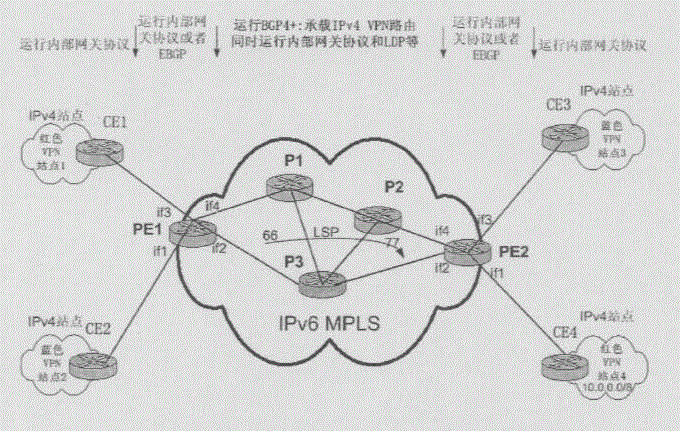
如图2所示,本发明应用的系统中,骨干网基于IPv6单AS,用户站点基于IPv4的BGP/MPLS VPN。站点1和站点4同属于VPN1,站点2和站点3同属于VPN2。同一VPN中的不同VPN站点之间可以通信,不同VPN中的站点不能互相访问。图2中各用户站点内运行内部网关协议如OSPF、IS-IS、RIP等,PE路由器均配置IPv4/v6双协议栈,IPv6MPLS骨干网中运行内部网关协议如OSPFv3、IS-ISv6、RIPng等和LDP协议。As shown in Figure 2, in the system applied by the present invention, the backbone network is based on IPv6 single AS, and the user sites are based on IPv4 BGP/MPLS VPN. Site 1 and Site 4 belong to VPN1, and Site 2 and Site 3 belong to VPN2. Different VPN sites in the same VPN can communicate with each other, but sites in different VPNs cannot communicate with each other. In Figure 2, interior gateway protocols such as OSPF, IS-IS, and RIP are running in each user site, PE routers are configured with IPv4/v6 dual protocol stacks, and interior gateway protocols such as OSPFv3, IS-ISv6, RIPng, etc. are running in the IPv6 MPLS backbone network. LDP protocol.
在本发明中,将BGP/MPLS VPN中的业务信息分为两大类:控制信息和数据信息。前者包括普通路由信息、VPN路由信息及建立LSP需要的LDP消息等,后者主要指用户的VPN业务流。普通路由信息如隧道标识、LSP等。In the present invention, the business information in the BGP/MPLS VPN is divided into two categories: control information and data information. The former includes general routing information, VPN routing information, and LDP messages needed to establish an LSP, etc., and the latter mainly refers to the user's VPN service flow. Common routing information such as tunnel ID, LSP, etc.
参见图3所示,以下以隧道为LSP为例,描述实现本发明的方法,具体如下:Referring to shown in Figure 3, the following takes the tunnel as an example of an LSP to describe the method for realizing the present invention, specifically as follows:
步骤301:目的VPN站点向出口PE发送目的VPN站点的地址为IPv4格式的VPN路由信息。Step 301: The destination VPN site sends VPN routing information whose address is in IPv4 format to the egress PE.
步骤302:出口PE收到该路由信息后,为该VPN路由分配一个LSP,利用该VPN路由信息、该LSP以及出口PE接收该路由信息的输入接口更新该VPN对应的兼容VRF以及MPLS标签转发表,并且设定路由目标属性。Step 302: After receiving the routing information, the egress PE allocates an LSP for the VPN route, and uses the VPN routing information, the LSP, and the input interface through which the egress PE receives the routing information to update the compatible VRF and MPLS label forwarding table corresponding to the VPN , and set the route target property.
需要说明的是,兼容VRF具有如下特点:支持IPv4地址与IPv4兼容IPv6地址输入输出自动转换功能;路由表项支持IPv4目的前缀和IPv6下一跳异类地址共存;具有普通VRF的全部功能。It should be noted that compatible VRF has the following features: it supports the automatic conversion function of input and output of IPv4 addresses and IPv4-compatible IPv6 addresses; routing table entries support the coexistence of IPv4 destination prefixes and IPv6 next-hop heterogeneous addresses; it has all the functions of ordinary VRFs.
VPN-IPv4兼容IPv6地址是本方案应用的一类特殊的地址。其中IPv4兼容IPv6地址,可以表示为0:0:0:0:0:0:w.x.y.z或::w.x.y.z(w.x.y.z是以点分十进制表示的IPv4地址),用于具有IPv4和IPv6两种协议的节点使用IPv6进行通信。而VPN-IPv4兼容IPv6地址采用RD(路由区分标识)和IPv4兼容IPv6地址的方式,在BGP中表示VPN路由的特殊性,从而巧妙的实现在骨干网中传递不同地址族的VPN路由。The VPN-IPv4 compatible IPv6 address is a special type of address used in this solution. Among them, the IPv4 compatible IPv6 address can be expressed as 0:0:0:0:0:0:w.x.y.z or ::w.x.y.z (w.x.y.z is an IPv4 address expressed in dotted decimal), which is used for nodes with both IPv4 and IPv6 protocols Use IPv6 for communication. The VPN-IPv4 compatible IPv6 address uses RD (Route Distinguishing Identity) and IPv4 compatible IPv6 address to represent the particularity of VPN routes in BGP, so as to cleverly realize the transmission of VPN routes of different address families in the backbone network.
兼容VRF包括输出路由目标属性、路由标识、目的地址、下一跳标识、输出接口等信息。MPLS标签转发表包括输入接口、入标签、处理模式、输出接口等参数。Compatible VRF includes output routing target attribute, routing ID, destination address, next hop ID, output interface and other information. The MPLS label forwarding table includes parameters such as input interface, input label, processing mode, and output interface.
所述更新该VPN对应的兼容VRF是指:将该VPN的路由标识所对应的目的地址设置为该路由信息中的IPv4地址,下一跳设置为源VPN站点的出口地址。The updating of the compatible VRF corresponding to the VPN refers to: setting the destination address corresponding to the routing identifier of the VPN as the IPv4 address in the routing information, and setting the next hop as the egress address of the source VPN site.
修改MPLS标签转发表是指:设置输入接口、入标签、处理模式以及输出接口的对应关系。这里,输入接口为出口PE接收数据流的接口。Modifying the MPLS label forwarding table refers to: setting the corresponding relationship between input interface, input label, processing mode and output interface. Here, the input interface is the interface through which the egress PE receives the data flow.
步骤303:出口PE根据包括自身路由信息和目的站点的路由信息的VPN路由以及自身为该VPN路由分配的LSP绑定封装到BGP的多协议可达属性中,并将为该VPN路由设定的路由目标属性(基于路由目标的扩展共同体属性)和上述封装到BGP的多协议可达属性中的VPN路由信息以及为该VPN路由分配的LSP通过UPDATE报文发送给入口PE。Step 303: The egress PE binds and encapsulates the VPN route including its own routing information and the routing information of the destination site into the multi-protocol reachable attribute of BGP according to the VPN route and the LSP allocated by itself for the VPN route, and sets the VPN route for the VPN route. The routing target attribute (based on the extended community attribute of the routing target), the VPN routing information encapsulated into the BGP multi-protocol reachable attribute, and the LSP allocated for the VPN route are sent to the ingress PE through an UPDATE message.
所述VPN路由信息中所述输入接口的路由信息为IPv6地址,或为利用输入接口的IPv4兼容IPv6地址。The routing information of the input interface in the VPN routing information is an IPv6 address, or an IPv4 compatible IPv6 address using the input interface.
步骤304:入口PE根据UPDATE报文中携带路由的输出目标属性值与PE中各兼容VRF的输入目标属性值进行对比,如果查到一个兼容VRF的输入目标中包含此路由的输出目标属性值,则将该VPN路由和LSP信息存入入口PE中该VPN对应的兼容VRF中,否则,将此路由丢弃。Step 304: The ingress PE compares the output destination attribute value of the route carried in the UPDATE message with the input destination attribute value of each compatible VRF in the PE. If an input destination compatible with VRF is found to contain the output destination attribute value of this route, Store the VPN route and LSP information in the compatible VRF corresponding to the VPN in the ingress PE; otherwise, discard the route.
当所述输入接口的路由信息为IPv6地址时,入口PE根据多协议可达属性中的目的前缀进行反映射得到目的地址;When the routing information of the input interface is an IPv6 address, the ingress PE performs inverse mapping according to the destination prefix in the multi-protocol reachability attribute to obtain the destination address;
当所述输入接口的路由信息为IPv4兼容IPv6地址时,直接根据多协议可达属性中的IPv4兼容IPv6地址进行反映射得到目的地址。When the routing information of the input interface is an IPv4-compatible IPv6 address, the destination address is obtained through inverse mapping directly according to the IPv4-compatible IPv6 address in the multi-protocol reachability attribute.
步骤305:当源VPN站点得到来自入口PE的VPN路由后,在自身的路由表中安装相关路由条目。源VPN站点内的其它路由器通过内部网关协议学习到这些路由,安装到自己的路由表中,且这些路由的下一跳都是到源CE的紧邻路由器地址。Step 305: After the source VPN site obtains the VPN route from the ingress PE, it installs relevant route entries in its own routing table. Other routers in the source VPN site learn these routes through the interior gateway protocol and install them in their own routing tables, and the next hops of these routes are the addresses of the routers next to the source CE.
步骤306:源VPN站点利用目的VPN站点的路由信息以及出口PE和入口PE之间的隧道向目的VPN站点发送业务流。Step 306: The source VPN site uses the routing information of the target VPN site and the tunnel between the egress PE and the ingress PE to send the service flow to the target VPN site.
下面以站点4的VPN路由通告到站点1,站点1向站点4发送VPN业务流为例,分别说明本发明中控制信息和数据信息的传递过程。Taking the VPN route notification of site 4 to site 1 and site 1 sending VPN service flow to site 4 as an example, the transfer process of control information and data information in the present invention will be described respectively.
参见图2所示,实施例一实现控制信息的处理过程如下:Referring to Fig. 2, the process of implementing the control information in Embodiment 1 is as follows:
(1)用户站点4内部的路由器运行统一的内部网关协议,经过协议扩散,用户站点设备CE4获得一条IPv4地址格式的内部路由10.0.0.0/8。(1) The routers inside the user site 4 run a unified interior gateway protocol. After protocol diffusion, the user site equipment CE4 obtains an internal route 10.0.0.0/8 in IPv4 address format.
(2)CE4向PE2发布站点4的路由信息,该路由信息为站点4的内部路由10.0.0.0/8。(2) CE4 advertises the routing information of site 4 to PE2, and the routing information is the internal route 10.0.0.0/8 of site 4.
具体发布方式可以不局限于某一种方式,如:CE4与PE2之间可以运行内部网关协议通知,也可以运行EBGP方式通知,也可以通过静态配置的路由方式通知。The specific publishing method is not limited to a certain method. For example, the interior gateway protocol notification can be run between CE4 and PE2, EBGP notification can also be run, and statically configured routing can also be used to notify.
(3)PE2收到来自CE4的路由10.0.0.0/8时,通过接收该路由信息的接口if1确定该路由标识,如:PE2的if1接口对应VPN1,if2对应VPN2,并且为CE4中VPN1对应的兼容VRF中的VPN站点路由分配一个LSP如100,该标签与PE2的接口if1对应,并且,PE2还为该路由分配一个输入接口如if2。PE2利用该LSP和输入接口if2、输出接口if1设置MPLS标签转发表。同时为该兼容VRF设定路由目标属性,即设置该VPN站点路由与设定好的输出路由目标属性的对应关系。(3) When PE2 receives the route 10.0.0.0/8 from CE4, it determines the route ID through the interface if1 that receives the routing information. For example, the if1 interface of PE2 corresponds to VPN1, and if2 corresponds to VPN2, and is the corresponding VPN1 in CE4 The VPN site route in the compatible VRF is assigned an LSP, such as 100, which corresponds to the interface if1 of PE2, and PE2 also assigns an input interface, such as if2, to the route. PE2 uses the LSP, input interface if2, and output interface if1 to set an MPLS label forwarding table. At the same time, the routing target attribute is set for the compatible VRF, that is, the corresponding relationship between the VPN site route and the set output routing target attribute is set.
见表1所示,PE2中的VPN1中对应的兼容VRF中,目的地址为10.0.0.0/8,下一跳地址为CE4,输出接口为if1,底部标签为100。As shown in Table 1, in the compatible VRF corresponding to VPN1 in PE2, the destination address is 10.0.0.0/8, the next-hop address is CE4, the output interface is if1, and the bottom label is 100.
目的地址 下一跳 路由标识 接口 底部标签 顶部标签Destination Address Next Hop Route ID Interface Bottom Label Top Label
10.0.0.0/8 CE4 RED if1 100 ------10.0.0.0/8 CE4 RED if1 100 ------
表1Table 1
参见表2所示,修改后的MPLS标签转发表中输入接口为if2,入标签设置为100,处理模式为“弹出标签”,输出接口为if1。As shown in Table 2, the input interface in the modified MPLS label forwarding table is if2, the incoming label is set to 100, the processing mode is "popup label", and the output interface is if1.
输入接口 入标签 处理 输出接口Input Interface Input Label Processing Output Interface
if2 100 弹出标签 if1if2 100 popup label if1
表2Table 2
(4)PE2将IPv6的VPN路由信息和PE2分配的标签LSP绑定封装在UPDATE报文中BGP的多协议可达属性中,发送给PE1。VPN路由信息包括路由标识RD和路由目标RT、VPN目的地址以及下一跳地址。(4) PE2 binds and encapsulates the IPv6 VPN routing information and the label LSP allocated by PE2 in the BGP multi-protocol reachability attribute in the UPDATE message, and sends it to PE1. VPN routing information includes routing identifier RD and routing target RT, VPN destination address and next hop address.
这里,由于PE2的输入接口直接面向IPv6骨干网,所以可以直接利用PE2输入接口的IPv6地址作为下一跳向PE1通告。表3示出了PE2对10.0.0.0/8这条路由的多协议可达属性的封装格式。Here, since the input interface of PE2 directly faces the IPv6 backbone network, the IPv6 address of the input interface of PE2 can be directly used as the next hop to notify PE1. Table 3 shows the encapsulation format of PE2's multi-protocol reachability attribute for the route 10.0.0.0/8.
表3table 3
并且,PE2将扩展共同体属性也被封装在UPDATE报文中发送出去。扩展共同体属性的封装如表4所示。In addition, PE2 also encapsulates the extended community attribute in the UPDATE message and sends it out. The encapsulation of extended community attributes is shown in Table 4.
表4Table 4
(5)PE1收到UPDATE报文后,根据基于路由目标的扩展共同体属性对来自PE2的IPv6VPN路由进行选择性地接收。(5) After receiving the UPDATE message, PE1 selectively receives the IPv6 VPN route from PE2 according to the extended community attribute based on the route target.
具体为:根据UPDATE报文中携带路由的输出目标属性值,与PE1中各兼容VRF的输入目标属性值进行比较,如果查到一个兼容VRF(也即VPN1对应的兼容VRF)的输入目标属性中包含该路由的输出目标属性值,则将路由::10.0.0.0/104存入该兼容VRF中;如果所有的兼容VRF的输入目标都不包含此值,则将此路由丢弃。Specifically: according to the output target attribute value of the route carried in the UPDATE message, compare it with the input target attribute value of each compatible VRF in PE1, if a compatible VRF (that is, the compatible VRF corresponding to VPN1) input target attribute value is found If the output destination attribute value of the route is included, the route::10.0.0.0/104 will be stored in the compatible VRF; if all the input destinations of the compatible VRF do not contain this value, the route will be discarded.
将路由::10.0.0.0/104存入该兼容VRF的过程是:The process of storing the route::10.0.0.0/104 into this compatible VRF is:
PE1从BGP多协议可达属性中取出目的前缀::10.0.0.0/104并反映射回10.0.0.0/8、取出下一跳PE2(3FFE:3210:FFFF::1)及标签100,并将该VPN路由存放到VRF RED中,如表5所示。PE1 extracts the destination prefix::10.0.0.0/104 from the BGP multi-protocol reachability attribute and maps back to 10.0.0.0/8, extracts the next hop PE2 (3FFE:3210:FFFF::1) and label 100, and The VPN route is stored in VRF RED, as shown in Table 5.
在PE1中保存的VPN1对应的兼容VRF中存入如下的路由信息:Store the following routing information in the compatible VRF corresponding to VPN1 saved in PE1:
表5table 5
这里由于10.0.0.0/8的下一跳PE2为非紧邻路由器,故而,想要到达PE2必须经过MPLS骨干网。通过查询目的为PE2的FEC,获得到达PE2的LSP入口标签66,并写入VRF表中。该LSP依据内部网关协议和LDP预先建立,与VPN路由无关。Here, because the next hop PE2 of 10.0.0.0/8 is a non-adjacent router, the MPLS backbone network must be used to reach PE2. By querying the FEC whose purpose is PE2, the
(6)当CE1通过内部网关协议或EBGP或者静态路由得到PE1的VPN路由10.0.0.0/8后,会在CE1的路由表中安装相关路由条目。(6) After CE1 obtains the VPN route 10.0.0.0/8 of PE1 through the interior gateway protocol or EBGP or static routing, it will install the relevant routing entries in the routing table of CE1.
这里,CE1与远端PE1之间可以运行内部网关协议,也可以运行EBGP甚至可以配置静态路由。除去一个站点即属于多个VPN的情况,一般都是一个接口对应一个VRF,这样当一条路由安装到PE1的某个兼容VRF中后,就可以直接决定向哪个接口对应的站点通告该路由。Here, the interior gateway protocol, EBGP, or even a static route can be configured between CE1 and the remote PE1. Except that one site belongs to multiple VPNs, generally one interface corresponds to one VRF. In this way, after a route is installed in a compatible VRF of PE1, it can directly decide which interface to advertise the route to.
(7)CE1站点将VPN路由10.0.0.0/8安装到自己的路由表后,站点内的其它路由器通过内部网关协议学习到这些路由,安装到自己的路由表中,且这些路由的下一跳都是到CE1的紧邻路由器地址。(7) After the CE1 site installs the VPN route 10.0.0.0/8 into its own routing table, other routers in the site learn these routes through the interior gateway protocol, install them in their own routing table, and the next hop of these routes Both are to the immediate router address of CE1.
(8)建立LSP。可以有多种不同的方法,如使用LDP或者RSVP。正如所期望的,LSP的建立可以与上层的IP-VPN路由相独立,也可以在通告VPN路由之后建立LSP。或者,在通告VPN路由之前预先建立LSP也可。(8) Establish LSPs. There are many different methods, such as using LDP or RSVP. As expected, the establishment of LSPs can be independent of the upper layer IP-VPN routes, or the LSPs can be established after the VPN routes are advertised. Alternatively, pre-establishing LSPs before advertising VPN routes is also acceptable.
业务数据信息的转发过程如下:The forwarding process of business data information is as follows:
(1)现在有一个目的地址为10.0.0.0/8的数据包从站点1某主机发出,首先发往作为其默认网关的路由器。如果在该路由器内已经有此路由,通过最长前缀匹配找到该路由,并转发到下一跳路由器;经过逐级转发最后到达CE1。(1) Now there is a data packet with the destination address 10.0.0.0/8 sent from a host at site 1, and it is first sent to the router as its default gateway. If there is already this route in the router, find the route through the longest prefix match, and forward it to the next-hop router; through level-by-level forwarding, it finally reaches CE1.
(2)在CE1的路由表中已经有的路由的数据包,下一跳为PE1,通过最长路径匹配,找到该路由,并将此数据包转发给PE1。(2) For the data packet of the existing route in the routing table of CE1, the next hop is PE1, the route is found through the longest path matching, and the data packet is forwarded to PE1.
(3)由于数据包是从PE1与CE1连接的接口if2收到的,因此PE1收到该包后就直接到输入接口if2对应的兼容VRF中查找该目的地址的路由。在RED VRF中找到对应的路由,采用两层标签机制进行MPLS数据报文封装,并根据出接口if2将该数据包转发出去。(3) Since the data packet is received from the interface if2 connecting PE1 and CE1, after receiving the packet, PE1 directly searches for the route of the destination address in the compatible VRF corresponding to the input interface if2. Find the corresponding route in RED VRF, use the two-layer label mechanism to encapsulate the MPLS data packet, and forward the data packet according to the outbound interface if2.
(4)在SP网络中,根据LSP进行标签交换,从相应接口转发给下面的P(P2、P3......)。依次传递,直到PE2的倒数第二跳Pn(这里n=2),因此在Pn弹出栈顶标签77,并从相应接口转发给PE2。(4) In the SP network, label switching is performed according to the LSP, and forwarded to the following P (P2, P3...) from the corresponding interface. It is transmitted in sequence until the penultimate hop Pn of PE2 (here n=2), so the top label 77 of the stack is popped at Pn and forwarded to PE2 from the corresponding interface.
(5)当数据包到达PE2后弹出底层标签,还原为IPv4数据包,因为在转发表中已经有标签对应的输出接口,因此无须查找VRF,直接将数据包从输出接口转发给CE4。(5) When the data packet arrives at PE2, the underlying label is popped up, and it is restored to an IPv4 data packet. Because there is already an output interface corresponding to the label in the forwarding table, there is no need to search for VRF, and the data packet is directly forwarded from the output interface to CE4.
(6)CE4收到数据包后,根据该IP包的目的地址,在本地路由表中进行最长路径匹配查找,找到对应的路由,将数据包发往下一跳路由器,最终转发至目的地。(6) After CE4 receives the data packet, according to the destination address of the IP packet, it performs the longest path matching search in the local routing table, finds the corresponding route, sends the data packet to the next-hop router, and finally forwards it to the destination .
下面举具体实施例二详细说明本发明的技术方案。The technical solution of the present invention will be described in detail below with specific example 2.
在本实施例中,PE路由器均配置双协议栈,各用户站点内运行内部网关协议如OSPF、IS-IS、RIP等,PE路由器均配置IPv4/v6双协议栈,IPv6MPLS骨干网中运行内部网关协议以及LDP协议,内部网关协议如OSPFv3、IS-ISv6、RIPng等。特别需要指出,PE面向IPv6骨干网的接口如PE2的if2、if4必须配置IPv4兼容IPv6地址。In this embodiment, the PE routers are all configured with dual protocol stacks, and internal gateway protocols such as OSPF, IS-IS, RIP, etc. are run in each user site, and the PE routers are all configured with IPv4/v6 dual protocol stacks, and the internal gateway protocols run in the IPv6MPLS backbone network protocol and LDP protocol, interior gateway protocols such as OSPFv3, IS-ISv6, RIPng, etc. In particular, it should be pointed out that the interfaces of PE facing the IPv6 backbone network, such as if2 and if4 of PE2, must be configured with IPv4-compatible IPv6 addresses.
实施例二控制信息的处理过程如下:Embodiment 2 The processing procedure of the control information is as follows:
(1)用户站点4内部的路由器运行统一的内部网关协议,经过协议扩散,用户站点设备CE4将获得了一条内部路由10.0.0.0/8。(1) The internal routers at user site 4 run a unified interior gateway protocol. After protocol diffusion, user site equipment CE4 will obtain an internal route 10.0.0.0/8.
(2)CE4与PE2之间可以运行内部网关协议,也可以运行EBGP甚至可以配置静态路由。CE4通过上述途径向PE2发布站点4内部IPv4路由10.0.0.0/8。(2) The interior gateway protocol, EBGP, or even static routing can be configured between CE4 and PE2. CE4 advertises the internal IPv4 route 10.0.0.0/8 of Site 4 to PE2 through the above methods.
(3)当PE2收到来自CE4的路由10.0.0.0/8时,将该路由存放到VPN1对应的兼容VRF中,下一跳设置为CE4的出口地址(IPv4地址),同时为该VPN路由信息设定路由目标属性。PE2为该兼容VRF中的VPN站点路由分配一个LSP,该LSP与PE2的输入接口对应,并修改MPLS标签转发表。(3) When PE2 receives the route 10.0.0.0/8 from CE4, it stores the route in the compatible VRF corresponding to VPN1, and sets the next hop as the egress address (IPv4 address) of CE4. Set route target properties. PE2 allocates an LSP for the VPN site route in the compatible VRF, the LSP corresponds to the input interface of PE2, and modifies the MPLS label forwarding table.
如表6所示,PE2保存的VPN1对应的兼容VRF中的内容为:As shown in Table 6, the content in the compatible VRF corresponding to VPN1 saved by PE2 is:
表6Table 6
参见表7所示,修改后的MPLS标签转发表如下:Referring to Table 7, the modified MPLS label forwarding table is as follows:
表7Table 7
(4)PE2将VPN路由信息和PE2分配的标签LSP绑定封装在UPDATE报文中BGP的多协议可达属性中,发送给PE1。VPN路由信息包括路由标识RD和路由目标RT、VPN目的地址以及下一跳地址。(4) PE2 binds and encapsulates the VPN routing information and the label LSP allocated by PE2 in the BGP multi-protocol reachability attribute in the UPDATE message, and sends it to PE1. VPN routing information includes routing identifier RD and routing target RT, VPN destination address and next hop address.
这里,由于PE2的输入接口if4直接面向IPv6骨干网,而且已经配置了IPv4兼容IPv6地址(::202.112.146.2),所以可以利用输入接口的IPv4兼容IPv6地址的反映射IPv4地址(202.112.146.2)作为下一跳向PE1通告。表8示出了PE2对10.0.0.0/8这条路由的多协议可达属性的封装格式。Here, since the input interface if4 of PE2 directly faces the IPv6 backbone network and has been configured with an IPv4-compatible IPv6 address (::202.112.146.2), the reverse mapping IPv4 address (202.112.146.2) of the IPv4-compatible IPv6 address of the input interface can be used Notify PE1 as the next hop. Table 8 shows the encapsulation format of PE2's multi-protocol reachability attribute for the route 10.0.0.0/8.
表8Table 8
(5)PE1可以根据基于路由目标的扩展共同体属性对来自PE2的IPv6VPN路由进行选择性地接收。根据UPDATE报文中携带路由的输出目标属性值,和PE中各兼容VRF的输入目标属性值进行对比,将查到一个兼容VRF的输入目标中包含此路由的输出目标属性值。后将10.0.0.0/8这路由存入这个兼容VRF中。若所有的兼容VRF的输入目标都不包含此值,则将此路由丢弃。在这里存入兼容VRF的过程也就是PE1从BGP多协议可达属性中取出目的前缀10.0.0.0、下一跳202.112.146.2及标签100,并将该VPN路由存放到兼容VRF中,如下所示。(5) PE1 can selectively receive the IPv6 VPN route from PE2 according to the extended community attribute based on the route target. According to the comparison between the output destination attribute value of the route carried in the UPDATE message and the input destination attribute values compatible with each VRF in the PE, it will be found that a VRF-compatible input destination contains the output destination attribute value of this route. Then store the route 10.0.0.0/8 into this compatible VRF. If all VRF-compatible input destinations do not contain this value, the route is discarded. The process of storing the compatible VRF here is that PE1 extracts the destination prefix 10.0.0.0, next hop 202.112.146.2, and label 100 from the BGP multi-protocol reachability attribute, and stores the VPN route in the compatible VRF, as shown below .
在PE1的RED VRF中存入如下的路由信息:Store the following routing information in the RED VRF of PE1:
表9Table 9
在这里下一跳的确定和顶部标签的加入值得注意。由于10.0.0.0/8的下一跳地址为IPv4地址,所以无法直接获得到达该IPv4地址的路由。兼容VRF通过将下一跳IPv4地址映射为IPv4兼容IPv6地址,而该兼容地址已经作为IGP路由在骨干网内扩散,故PE2被确定为下一跳路由器。而PE2为非紧邻路由器,想要到达PE2必须经过MPLS骨干网。通过查询目的为PE2的FEC,获得到达PE2的LSP入口标签66,并写入PE1中VPN1对应的兼容VRF中。The determination of the next hop and the addition of the top label are worth noting here. Since the next hop address of 10.0.0.0/8 is an IPv4 address, the route to this IPv4 address cannot be obtained directly. Compatible VRF maps the next-hop IPv4 address to an IPv4-compatible IPv6 address, and the compatible address has been diffused in the backbone network as an IGP route, so PE2 is determined as the next-hop router. However, PE2 is a non-adjacent router, and the MPLS backbone network must be used to reach PE2. By querying the FEC whose purpose is PE2, the
(6)当CE1通过内部网关协议或EBGP或者静态路由得到PE1的VPN路由10.0.0.0/8后,会在CE1的路由表中安装相关路由条目。(6) After CE1 obtains the VPN route 10.0.0.0/8 of PE1 through the interior gateway protocol or EBGP or static routing, it will install the relevant routing entries in the routing table of CE1.
CE1与远端PE1之间可以运行内部网关协议,也可以运行EBGP甚至可以配置静态路由。并且除一个站点属于多个VPN的情况外,一般都是一个接口对应一个兼容VRF,这样当一条路由安装到PE1的某个兼容VRF中后,就可以直接决定向哪个接口对应的站点通告该路由。The interior gateway protocol, EBGP, or even static routing can be configured between CE1 and remote PE1. And except for the case where a site belongs to multiple VPNs, generally one interface corresponds to one compatible VRF, so that when a route is installed in a compatible VRF of PE1, it can directly decide which interface to advertise the route to. .
(7)CE1站点内的其它路由器通过内部网关协议学习到这些路由,装到自己的路由表中,且这些路由的下一跳都是到CE1的紧邻路由器地址。(7) Other routers in the CE1 site learn these routes through the interior gateway protocol and install them in their own routing tables, and the next hops of these routes are all the addresses of the routers next to CE1.
(8)建立LSP。同实施例一中步骤(8)。(8) Establish LSPs. Same as step (8) in Example 1.
经过基于上述实施例二所示的转发控制信令后,之后进行的数据转发过程与实施例一业务数据信息的转发的步骤相同,这里不再赘述。After the forwarding control signaling based on the second embodiment above, the subsequent data forwarding process is the same as the forwarding steps of the service data information in the first embodiment, which will not be repeated here.
Claims (8)
Priority Applications (1)
| Application Number | Priority Date | Filing Date | Title |
|---|---|---|---|
| CNB2005101174980A CN100433691C (en) | 2005-11-02 | 2005-11-02 | Routing method of virtual special network |
Applications Claiming Priority (1)
| Application Number | Priority Date | Filing Date | Title |
|---|---|---|---|
| CNB2005101174980A CN100433691C (en) | 2005-11-02 | 2005-11-02 | Routing method of virtual special network |
Publications (2)
| Publication Number | Publication Date |
|---|---|
| CN1852214A CN1852214A (en) | 2006-10-25 |
| CN100433691C true CN100433691C (en) | 2008-11-12 |
Family
ID=37133684
Family Applications (1)
| Application Number | Title | Priority Date | Filing Date |
|---|---|---|---|
| CNB2005101174980A Expired - Fee Related CN100433691C (en) | 2005-11-02 | 2005-11-02 | Routing method of virtual special network |
Country Status (1)
| Country | Link |
|---|---|
| CN (1) | CN100433691C (en) |
Cited By (2)
| Publication number | Priority date | Publication date | Assignee | Title |
|---|---|---|---|---|
| CN101834794A (en) * | 2010-05-06 | 2010-09-15 | 杭州华三通信技术有限公司 | Method and device for forwarding message through backbone network |
| WO2014079369A1 (en) * | 2012-11-21 | 2014-05-30 | Hangzhou H3C Technologies Co., Ltd. | Forwarding a packet in a network |
Families Citing this family (13)
| Publication number | Priority date | Publication date | Assignee | Title |
|---|---|---|---|---|
| CN101237343B (en) * | 2007-02-02 | 2011-08-10 | 华为技术有限公司 | Method for quick failure switching and quick switching system |
| CN101296179B (en) * | 2007-10-29 | 2011-01-26 | 清华大学 | Method for IPv6 repeating vector IPv4/6 through inverse path |
| CN101262407B (en) * | 2008-04-14 | 2011-05-11 | 中兴通讯股份有限公司 | A method for virtual router to establish tunnel |
| WO2009150490A1 (en) * | 2008-06-09 | 2009-12-17 | Nokia Corporation | Method, apparatus, and computer program product for communication routing |
| WO2011051594A1 (en) * | 2009-10-30 | 2011-05-05 | France Telecom | METHODS AND DEVICES FOR ROUTING DATA PACKETS BETWEEN IPv4 AND IPv6 NETWORKS |
| CN102137173B (en) * | 2010-12-27 | 2014-09-03 | 华为技术有限公司 | Routing information distributing method, equipment, virtual special network system |
| CN102195871B (en) * | 2011-01-07 | 2014-02-19 | 北京华为数字技术有限公司 | Method for controlling service flow forwarding path in MPLS VPN network |
| CN102904814B (en) * | 2012-10-19 | 2015-09-16 | 福建星网锐捷网络有限公司 | Data transmission method, source PE, object PE and data transmission system |
| CN103986654B (en) * | 2014-05-05 | 2017-11-28 | 新华三技术有限公司 | A kind of LSP generation methods and equipment |
| CN107370675B (en) * | 2016-05-13 | 2021-02-23 | 华为技术有限公司 | Method and node for route dissemination |
| CN106878137B (en) * | 2016-12-29 | 2020-08-04 | 新华三技术有限公司 | Route learning method and device |
| CN108768861B (en) * | 2018-06-29 | 2021-01-08 | 新华三信息安全技术有限公司 | Method and device for sending service message |
| CN111147376B (en) * | 2019-12-30 | 2022-04-26 | 杭州迪普科技股份有限公司 | Route updating method, device, equipment and medium |
Citations (4)
| Publication number | Priority date | Publication date | Assignee | Title |
|---|---|---|---|---|
| CN1564542A (en) * | 2004-04-20 | 2005-01-12 | 清华大学 | Tunnel set-up method for carrying out internet of IPV4 network on IPV6 network |
| CN1571396A (en) * | 2003-07-18 | 2005-01-26 | 华为技术有限公司 | An implementing method for switching ZONET in IPv6 network |
| US20050025157A1 (en) * | 2003-05-26 | 2005-02-03 | Pennec Jean-Francois Le | System for converting data based upon IPv4 into data based upon IPv6 to be transmitted over an IP switched network |
| WO2005025141A1 (en) * | 2003-09-05 | 2005-03-17 | Ntt Docomo, Inc. | Communication between fixed terminals of an ipv4 private network and an ipv6 global network interconnected through the ipv4-internet |
-
2005
- 2005-11-02 CN CNB2005101174980A patent/CN100433691C/en not_active Expired - Fee Related
Patent Citations (4)
| Publication number | Priority date | Publication date | Assignee | Title |
|---|---|---|---|---|
| US20050025157A1 (en) * | 2003-05-26 | 2005-02-03 | Pennec Jean-Francois Le | System for converting data based upon IPv4 into data based upon IPv6 to be transmitted over an IP switched network |
| CN1571396A (en) * | 2003-07-18 | 2005-01-26 | 华为技术有限公司 | An implementing method for switching ZONET in IPv6 network |
| WO2005025141A1 (en) * | 2003-09-05 | 2005-03-17 | Ntt Docomo, Inc. | Communication between fixed terminals of an ipv4 private network and an ipv6 global network interconnected through the ipv4-internet |
| CN1564542A (en) * | 2004-04-20 | 2005-01-12 | 清华大学 | Tunnel set-up method for carrying out internet of IPV4 network on IPV6 network |
Cited By (3)
| Publication number | Priority date | Publication date | Assignee | Title |
|---|---|---|---|---|
| CN101834794A (en) * | 2010-05-06 | 2010-09-15 | 杭州华三通信技术有限公司 | Method and device for forwarding message through backbone network |
| WO2014079369A1 (en) * | 2012-11-21 | 2014-05-30 | Hangzhou H3C Technologies Co., Ltd. | Forwarding a packet in a network |
| US9479420B2 (en) | 2012-11-21 | 2016-10-25 | Hewlett Packard Enterprise Development Lp | Forwarding a packet in a network |
Also Published As
| Publication number | Publication date |
|---|---|
| CN1852214A (en) | 2006-10-25 |
Similar Documents
| Publication | Publication Date | Title |
|---|---|---|
| CN111865898B (en) | Communication method, device and system based on flow rule protocol | |
| US7688829B2 (en) | System and methods for network segmentation | |
| US8151000B1 (en) | Transparently providing layer two (L2) services across intermediate computer networks | |
| CN101340372B (en) | Number automatic routing method, updating method, revocation method, router and equipment | |
| US8117338B2 (en) | Border gateway protocol procedures for multi-protocol label switching and layer-2 virtual private networks using Ethernet-based tunnels | |
| US9055001B2 (en) | Border gateway protocol extended community attribute for layer-2 and layer-3 virtual private networks | |
| CN103685022B (en) | Message forwarding method and service provider network edge equipment | |
| US9860169B1 (en) | Neighbor resolution for remote EVPN hosts in IPV6 EVPN environment | |
| US8531941B2 (en) | Intra-domain and inter-domain bridging over MPLS using MAC distribution via border gateway protocol | |
| CN100372336C (en) | Multi-protocol label switching virtual private network and control and forwarding method thereof | |
| CN100505674C (en) | Message forwarding method, system and edge device in virtual private network | |
| EP3211839A1 (en) | Split-horizon packet forwarding in a multi-home pbb-evpn network | |
| EP1713197A1 (en) | A method for implementing the virtual leased line | |
| US20040177157A1 (en) | Logical grouping of VPN tunnels | |
| CN110912795A (en) | Transmission control method, node, network system and storage medium | |
| CN111385207A (en) | Service data forwarding method, network device and network system | |
| US9954694B2 (en) | Traffic black holing avoidance and fast convergence for active-active PBB-EVPN redundancy | |
| CN100433691C (en) | Routing method of virtual special network | |
| CN102739501B (en) | Message forwarding method and system in two three layer virtual private networks | |
| CN107026796A (en) | A VPN route notification method, data flow forwarding method, and related equipment | |
| CN106936714B (en) | A VPN processing method and PE device and system | |
| CN103326915A (en) | Method, device and system for achieving three-layer VPN | |
| CN101355487A (en) | Method and apparatus for distributing label | |
| CN102474451A (en) | Connecting inner and outer MPLS labels | |
| CN101136832A (en) | Multi-protocol label switching virtual private network and its control and forwarding method |
Legal Events
| Date | Code | Title | Description |
|---|---|---|---|
| C06 | Publication | ||
| PB01 | Publication | ||
| C10 | Entry into substantive examination | ||
| SE01 | Entry into force of request for substantive examination | ||
| C14 | Grant of patent or utility model | ||
| GR01 | Patent grant | ||
| TR01 | Transfer of patent right | ||
| TR01 | Transfer of patent right |
Effective date of registration: 20171212 Address after: Tiefu iron rich street Pizhou city 221331 Jiangsu city of Xuzhou province (Cultural Center) Patentee after: Pan Rongqiong Address before: 510640 Guangdong City, Tianhe District Province, No. five, road, public education building, unit 371-1, unit 2401 Patentee before: GUANGDONG GAOHANG INTELLECTUAL PROPERTY OPERATION Co.,Ltd. Effective date of registration: 20171212 Address after: 510640 Guangdong City, Tianhe District Province, No. five, road, public education building, unit 371-1, unit 2401 Patentee after: GUANGDONG GAOHANG INTELLECTUAL PROPERTY OPERATION Co.,Ltd. Address before: 518129 Bantian HUAWEI headquarters office building, Longgang District, Guangdong, Shenzhen Patentee before: HUAWEI TECHNOLOGIES Co.,Ltd. |
|
| CB03 | Change of inventor or designer information | ||
| CB03 | Change of inventor or designer information |
Inventor after: Shang Yutao Inventor before: Zhang Hongke Inventor before: Gao Shuai Inventor before: Li Defeng Inventor before: Gu Zhihui Inventor before: Huo Hongwei |
|
| TR01 | Transfer of patent right | ||
| TR01 | Transfer of patent right |
Effective date of registration: 20180129 Address after: 065000 Langfang City, Hebei province Anci district flourishing street 4 No. 3 Patentee after: Shang Yutao Address before: Tiefu iron rich street Pizhou city 221331 Jiangsu city of Xuzhou province (Cultural Center) Patentee before: Pan Rongqiong |
|
| TR01 | Transfer of patent right | ||
| TR01 | Transfer of patent right |
Effective date of registration: 20181105 Address after: 221300 Liu Gou Village, Zou Zhuang Town, Pizhou City, Xuzhou, Jiangsu Patentee after: Xuzhou Yong Wei Wood Industry Co.,Ltd. Address before: 065000 No. 4, Chang Ming Street, Anci District, Langfang, Hebei, 3 Patentee before: Shang Yutao |
|
| CF01 | Termination of patent right due to non-payment of annual fee | ||
| CF01 | Termination of patent right due to non-payment of annual fee |
Granted publication date: 20081112 Termination date: 20181102 |