CN100425900C - Self-balance type drawing prevention device for pipe joint - Google Patents
Self-balance type drawing prevention device for pipe joint Download PDFInfo
- Publication number
- CN100425900C CN100425900C CNB2006100640376A CN200610064037A CN100425900C CN 100425900 C CN100425900 C CN 100425900C CN B2006100640376 A CNB2006100640376 A CN B2006100640376A CN 200610064037 A CN200610064037 A CN 200610064037A CN 100425900 C CN100425900 C CN 100425900C
- Authority
- CN
- China
- Prior art keywords
- joint
- inner face
- rigid body
- body parts
- self
- Prior art date
- Legal status (The legal status is an assumption and is not a legal conclusion. Google has not performed a legal analysis and makes no representation as to the accuracy of the status listed.)
- Expired - Fee Related
Links
- 230000002265 prevention Effects 0.000 title claims abstract description 14
- 229910000831 Steel Inorganic materials 0.000 description 30
- 239000010959 steel Substances 0.000 description 30
- 238000000034 method Methods 0.000 description 10
- 230000000694 effects Effects 0.000 description 7
- 244000287680 Garcinia dulcis Species 0.000 description 3
- 229910000975 Carbon steel Inorganic materials 0.000 description 2
- 230000008485 antagonism Effects 0.000 description 2
- 239000010962 carbon steel Substances 0.000 description 2
- 238000006073 displacement reaction Methods 0.000 description 2
- 238000009434 installation Methods 0.000 description 2
- 230000003068 static effect Effects 0.000 description 2
- 229910001018 Cast iron Inorganic materials 0.000 description 1
- 229910001374 Invar Inorganic materials 0.000 description 1
- BZHJMEDXRYGGRV-UHFFFAOYSA-N Vinyl chloride Chemical compound ClC=C BZHJMEDXRYGGRV-UHFFFAOYSA-N 0.000 description 1
- 230000003321 amplification Effects 0.000 description 1
- 230000015572 biosynthetic process Effects 0.000 description 1
- 238000010276 construction Methods 0.000 description 1
- 230000002844 continuous effect Effects 0.000 description 1
- 230000006378 damage Effects 0.000 description 1
- 230000006866 deterioration Effects 0.000 description 1
- PCHJSUWPFVWCPO-UHFFFAOYSA-N gold Chemical compound [Au] PCHJSUWPFVWCPO-UHFFFAOYSA-N 0.000 description 1
- 239000010931 gold Substances 0.000 description 1
- 229910052737 gold Inorganic materials 0.000 description 1
- 238000007373 indentation Methods 0.000 description 1
- 230000007774 longterm Effects 0.000 description 1
- 238000003199 nucleic acid amplification method Methods 0.000 description 1
- 230000002093 peripheral effect Effects 0.000 description 1
- 230000010349 pulsation Effects 0.000 description 1
- 230000000630 rising effect Effects 0.000 description 1
- 238000005096 rolling process Methods 0.000 description 1
- 238000004381 surface treatment Methods 0.000 description 1
- 239000002699 waste material Substances 0.000 description 1
Images


Landscapes
- Joints Allowing Movement (AREA)
- Mutual Connection Of Rods And Tubes (AREA)
Abstract
The present invention provided a self-balance type drawing prevention device, wherein a plurality of rigid members capable of biting a pipe body outer face and a joint inner face are approximately evenly arranged in the circumferential direction in a space having a wedge-shaped cross-section and formed by the cylindrical pipe body outer face and the conical joint inner face, the rigid members are composed of rotators rotating around a shaft in the circumferential direction of the pipe body and movable in the drawing direction when the external force in the drawing direction acts on the pipe body and the joint. Conditions to rotate the rigid bodies by the external force in the drawing direction, are that an included angle 2[alpha] between the pipe body outer face and the joint inner face in the wedge-shaped space is 17 degrees +-7 degrees, and an outer diameter of the rigid member is two times or more of a minimum gap [Delta]g between the pipe body outer face and the joint inner face.
Description
Technical field
The present invention relates to a kind of self-balance type drawing prevention device of pipe joint, this pipe joint has following structure: along the circumferential direction approximately the configuration of proportional spacing ground is a plurality of in the space of the wedge-shaped cross section shape that is formed by columnar body outside and conical joint inner face snaps into outside the body and the rigid body parts of joint inner face.
Background technique
For example have following method, thus promptly by the rubber package with fastening forcefully first method that keeps on the pipe connector of building waste pipe that drainage system uses that is installed to of body; Thereby open the holding element shown in flat 7-19690 number and keep body to be connected to second method on the joint by Japan is real; Perhaps register shown in No. 3099370 as Japanese Utility Model, configuration rigid body ball on the flange of joint and the rubber package between the body when applying pulling capacity on body, thereby promotes third party's method that the performance of rigid body ball prevents withdrawal force on the body surface.These piecing devices apply certain confining force by rubber package or holding element, Metal Ball etc. on the body outside, via the create antagonism effect of pulling capacity of body of its maximum static friction force.
Specifically describe by Figure 13, Figure 14, first method is the rubber package of the fastening installation ring-type outside body by joint body and flange, and generation confining force R1, second method is further to increase for the confining force with first method, use holding element to carry out fastening installation around body, closely keep (confining force R2).Third party's method is, insert the rigid body ball between the rubber package and flange of first method in a plurality of places, and when body that passes through the fastening erection joint of bolt and nut and flange, the rigid body ball snaps into the body surface by the pressure of flange and rubber package, performance confining force R3.
If investigate the mechanics situation that the body of traditional piecing devices is extracted, produce frictional force f pro rata with the plus-pressure R of confining force R1-R3 that applies as vertical pressure in body outside and so on, its proportionality constant μ is defined as friction factor.Apply pulling capacity F on body, during f=μ R<F, body is towards extracting the only mobile Δ l of direction.Shown in Figure 15 by the body of 4 inches of external force F moment of torsion stretching calibers the time, body is from the measured value of the amount of the extracting Lmm of piecing devices.
1) as shown in figure 15, initial, even external force F increases, moving of the amount of extracting L also is small Δ l.When this expression μ is coefficient of maximum static friction.Be accompanied by the body setting in motion, μ becomes the coefficient of kinetic friction, and it is big that the increase of the amount of extracting becomes, and finally comes off.
2) because coefficientoffriction is different numerical value according to the surface state of body, rubber package, perhaps plus-pressure R also changes because of the bolt of joint body and flange, the inhomogeneous of fastening installing force of nut, thereby also earthquake of frictional force f=μ R, as shown in figure 15, anti-pulling capacity is different significantly because of goods.
3) in traditional piecing devices, because the mechanism of the anti-pulling capacity of performance depends on the confining force that is imposed on body by the rubber package, the deterioration of rubber and the rotten performance that directly influence piecing devices (manage do not come off, water-tight).Thereby after long-term, be difficult to keep reliability.
(patent documentation 1) Japan is real to open flat 7-19690 number
(patent documentation 2) Japanese Utility Model is registered No. 3099370
Summary of the invention
(problem to be addressed by invention)
The present invention be conceived to aforementioned some, its problem is to provide a kind of self-balance type drawing prevention device, wherein for pipe joint, the pulling capacity that affacts on the body is fed back into confining force.In addition, another problem of the present invention is to provide a kind of pipe joint self-balance type drawing prevention device that all keeps body till destroying.
(solving the means of problem)
In order to solve aforementioned problems, the present invention provides the means of following formation: in the space by columnar body outside and the formed wedge-shaped cross section shape of conical joint inner face, along the circumferential direction approximately the configuration of proportional spacing ground is a plurality of is created in outside the body and the rigid body parts of joint inner face interlock, external force in the direction of drawing body and joint is done the time spent, these rigid body parts are formed on the rotor that rotates on the axle circumference of body circumferencial direction and can move towards the drawing direction, the condition that the rigid body parts is rotated as external force by above-mentioned drawing direction, angle 2 α that form between the body outside in the space of wedge-shaped cross section shape and the joint inner face are 17 degree ± 7 degree, and the external diameter of rigid body parts is more than 2 times of minimum clearance Δ g between body outside and the joint inner face.
Principle of the present invention
Traditional pipe connector as shown in Figure 14, the plus-pressure R that acts on body of confining force R1-R3 and so on is certain, thereby it is also certain with the frictional force f of pulling capacity F antagonism, relative with it, the present invention is characterised in that, in case realize that by running principle pulling capacity F imposes on body and this power increases, then frictional force f and this F also self balancing confining force system of increase pro rata.
According to the present invention, the amount of extracting when body is upheld by external force is in a ratio of part to 1/10 with traditional pipe connector, can provide and not produce the epoch-making new piecing devices that body comes off till the limit of rupture of joint body.In addition, the pulling capacity of body also can be produced by the pulsation of hydraulic pressure in the pipe in the discharge pipe line system or hydraulic pressure not only from the body external action relatively.
In the present invention shown in Fig. 1 to Figure 12.Form wedge-shaped cross section ABC and constitute wedge shape space by the cylindrical shape of body outside and the taper shape of flange inner face, in this wedge shape space, being held outside body and between the flange inner face, approximately disposing a plurality of to the proportional spacing layout on the pipe periphery is the spherical rotor of radius r or the rigid body parts that cylindric rotor is made by unification.At this moment, section angle ∠ ABC=2 α, the gap between body and the flange keeps Δ g along body.
In Fig. 4, in case in Fig. 4, on the body length direction, apply pulling capacity Δ F, the rigid body parts that constitute by the rotor of clamping in body and the flange produce by with the coefficientoffriction 1 of each, the driving torque P of μ 2 decisions, and with pulling capacity Δ F equidirectional on only mobile Δ l (similar) with the principle of cylinder.Center O by the rigid body parts moves to O ', and Δ r=Δ l sin α partly snaps into columnar body outside and conical flange inner face in the radius of rigid body parts, and each face produces pressure Δ R relatively.This is when squeezing into wedge by power Δ K, with to set up Δ K=2 Δ R (sin α+μ cos α) between the plus-pressure Δ R the same in the ABC of the space of wedge-shaped cross section shape.Under the occasion of the present invention, though power Δ K does not directly impose on the rigid body parts, but because the driving torque by the rigid body parts that constitute by rotor that produce by the pulling capacity Δ F that imposes on body, make the rigid body parts that constitute by rotor move, so can see of equal valuely just as squeezing in the interior volume of wedge-shaped cross section shape.
That is, if a, b are constant, then
Δl=aΔF (1)
ΔR=bΔr=bΔlsinα (2)
Thereby, Δ R/ Δ F=ab sin α=definite value (3)
That is,, then produce plus-pressure R as confining force by this power in case produce pulling capacity F at body, with the increase part Δ F of pulling capacity pro rata (with Δ F balance) produce the increase part Δ R of confining force.The confining force R1 of the expectation that is applied by the rubber package is as the power that has been applied in.
(invention effect)
Device of the present invention, work by the mechanism that as above describes in detail, pulling capacity F is fed to the rigid body parts that are made of rotor and as confining force R through driving torque, for drawing needs bigger power F, owing to have so-called self-balance type (self balance type) mechanism, prevent the extracting of body, till destroying, all keep the continuous effect of body so have.
Description of drawings
Fig. 1 is the sectional arrangement drawing of integral body that the self-balance type drawing prevention device of pipe joint of the present invention is shown.
Fig. 2 is the perspective view of an example that is illustrated in the embodiment's 1 who uses in the device of Fig. 1 package.
Fig. 3 is master's amplification profile partly of the device of Fig. 1.
Fig. 4 is the explanatory drawing that is used to resolve the mechanical mechanism of device of the present invention.
Fig. 5 is the perspective view that following state is shown: the conical spatial configuration rigid body parts between body outside and joint inner face are spheroid.
Fig. 6 illustrates the steel ball number of the embodiment of the invention 1 and the chart of displacement.
Fig. 7 is the sectional arrangement drawing of major component that the device of embodiments of the invention 2 is shown.
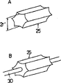
Fig. 8 illustrates an example of the embodiment's 2 that the device of Fig. 7 uses package, and Fig. 8 A is a perspective view, and Fig. 8 B is the front elevation of an example that the rigid body parts of package configuration are shown.
Fig. 9 illustrates the rigid body parts that the device of Fig. 7 uses, and Fig. 9 A is the perspective view of the type that do not supported by back shaft, and Fig. 9 B is the perspective view of the type that supported by back shaft.
Figure 10 is illustrated in the state of the rigid body parts that Fig. 9 B has been installed on the package, and Figure 10 A is the sectional drawing of frontal, and Figure 10 B is the sectional drawing of side surface direction.
Figure 11 is the perspective view that prevents to extract indentation that embodiment 2 device is shown.
Figure 12 is the chart that the effect of embodiments of the invention 2 is shown.
Figure 13 illustrates the front elevation that tradition is extracted the effect of anti-locking apparatus.
Figure 14 is the sectional arrangement drawing that illustrates with the effect of Figure 13 same apparatus.
Figure 15 is the chart of effect that the device of Figure 13, Figure 14 is shown.
Description of reference numerals
The flange 17 of the self-balance type drawing prevention device 11 of 10-pipe joint of the present invention, 24-body 12-body outside 13-joint 14-body 15-flange 16-body, the spheroid that 26-package 18-bolt 19-nut 20-wedge-like space 21-joint inner face 23-is the rigid body parts for example steel ball 25-are the gear shape cylinder part 27-recess 28-flange periphery 29-steel ball patchhole of rigid body parts
Embodiment
Illustrate in greater detail the present invention with reference to the following drawings.Fig. 1-6 illustrates an example of the self-balance type drawing prevention device 10 of pipe joint of the present invention, symbol 11 is a body, 12 is its outside, 13 is joint, and have body 14 and flange 15, the package 17 of the rubber system of inserting between flange 16 by can fasteningly forcefully being installed in body 14 in the fastening of the bolt of installing on two flanges 15,16 18, nut 19 and the flange 15.14a represents the inclination inner face of joint body side, 17a represent the rubber package in conjunction with terminal.
Constitute space 20 by the cylindrical shape of the outside 12 of body 11 with at the taper shape that the inner face 21 of the flange 15 of joint 13 forms with wedge-shaped cross section shape ABC.The package 17 of rubber system has the holding part 22 of the cone-shaped in the above-mentioned space 20 that enters between body outside 12 and joint inner face 21, a plurality of rigid body parts of being made by rotor 23 of roughly even in a circumferential direction compartment of terrain configuration on this holding part 22.In addition, holding part 22 has thinner wall section 22a, and it is provided with so that can freely move to a certain degree from the body portion of package 17.
In addition, in Fig. 3, Fig. 4, Fig. 5, some A is the point of joint inner face 21, and some B is the elongation line of joint inner face 21 and the intersection point of body outside 12, point C is the point of body outside 12, and whole some A, B, C is positioned on the same plane by body 11 radius centered directions.In addition, r represents the radius of the rigid body parts 23 made by rotor, and Δ g represents the minimum clearance between body outside 12 and the joint inner face 21.Relation between diagrammatically shown wedge-like space 20 that forms by body outside 12 and joint inner face 21 of Fig. 5 and the spherical rigid body parts 23 that in this wedge-like space 20, dispose.
Embodiment 1 (referring to figs. 1 through Fig. 6)
Present embodiment is suitable for the piping of 4 inches of nominals, and is the self-balance type drawing prevention device of pipe joint.The body 14 of joint 13 and flange 15 are made by cast iron, and employed body 11 is a piping with carbon steel steel pipe (SGP).Select the rigid body parts 23 made by rotor according to the form of employed body 11.Made by SGP under the occasion of body 11, its surface has antirust inferior lead-coat, because coefficient of rolling friction μ 2 is relatively large, therefore the rigid body parts of being made by rotor 23 are steel ball.
The angle of the wedge shape space 20 that body outside 12 and flange part inner face 21 constitute is 2 α=17 degree, the radius r=2.4mm of the rigid body parts of being made by steel ball 23.Fig. 6 is illustrated under the occasion that changes the steel ball number, and the body of body pulling capacity F (newton) is extracted the measured value of length (mm) relatively.Also write down tradition product measured value under the same conditions simultaneously in the lump.
The steel ball number is under 3,4 and 6 s' the occasion, shown in chart: though data stop near the about 15mm of the amount of extracting, thereby owing to rotate as the steel ball of rigid body parts 23 with the drawing interlock of body 11 and to move, come off from flange at last.In addition, under the occasion of 12 of embodiment's steel balls, illustrate as follows: though near the no show amount of the extracting 15mm, and stop at the 12.5mm place, the piecing devices body destroyed by 60000N.Content below this graph shows.
1) traditional relatively product, 12 steel balls of device equipment of the present invention, the body pulling capacity has the endurance more than 5 times relatively, is greatly improved.Be not to come off at 60000N place body, but the mo(u)lding of piecing devices self produces destruction, retaining mechanism of this expression joint is still in work.
2) the body amount of the extracting L that each measured load illustrates relative body pulling capacity F among the embodiment 1 is roughly straight line, i.e. Δ F/ Δ l=definite value, and (1) formula is set up.And Δ P is as the endurance F of the micro-displacement of relative 1 steel ball,
ΔP=ΔF/Δl·n (4)
Here n is the steel ball number
(table 1)
| Steel ball is counted N | 3 | 4 | 6 | 12 |
| ΔP N/mm | 220 | 250 | 220 | 220 |
This result illustrates as shown in table 1, and Δ P is the definite value of about 220 newton/mm, and (3) formula is set up, i.e. rotation by steel ball in the wedge shape space, and (P: the R ratio) self balancing ground increases corresponding to the drag of the increase of the body amount of extracting F.
3) though the increase of invar nodule number and drag increase, these steel balls are used for disperseing this load on body and flange.In the very few occasion of steel ball number, when steel ball rotated, R produced recess on body because of load, takes off pipe when finally destroying flange periphery.By increasing the steel ball number, load R disperses on body, so that also can tolerate the above load of the limit of rupture of joint mo(u)lding.These are understood easily by experience.
The body 24 of connecting object is under the occasion of hard vinyl chloride (VP), because the body surface is very level and smooth, and easy deformation, thereby the gear shape cylinder part is suitable for as rigid body parts (Fig. 9 A, B).Body 24 is of a size of under 4 inches the occasion identical with aforementioned each example, and shown in Fig. 8 A, B, the rigid body parts of being made by 12 cylinder parts 25 insert in the recess 27, are arranged on the flange side outer edge of rubber package 26 these recess 27 proportional spacings.The number of rigid body parts 25 with 4 inches pipes as representative, also appropriate for the body of other size.
The occasion of the rigid body parts made from steel ball on the principle 25 is identical, and by the drawing of VP tubulation body 24, the tooth of rigid body parts 25 VP tubulation body 24 surfaces of nipping are guaranteed driving torque, and moved through the inside of wedge shape space 20 towards flange periphery 28.Confining force increases like this.In addition, because the structure beyond the symbol that newly illustrates here is same with structure before this, be not described in detail thereby do not repeat to quote symbol.Figure 12 illustrates the measured value of the amount of extracting of VP tubulation body 24 of relative embodiment's 2 pulling capacity F.According to Figure 12, though understand in traditional joint there is not drag, it improves significantly.In addition, by on the surface of the VP tubulation body 24 after the experiment, the certain remaining trace of tooth pitch of the rigid body parts of being made by the gear shape cylinder part 25 understands as theory to rotate.
The present invention sets up each condition of requirement:
1) as the radius of gyration r and the angle α of the rigid body parts of rotor
In Fig. 4, the gap of uniform Δ g is set between body and flange.As an example, the boundary dimension φ p of 4 inches carbon steel steel pipes, flange internal diameter size φ f are respectively
φp=114.3±0.8mm
φf=117.4±0.5mm
Thereby, maximum Δ g=1/2 * { the minimum φ p}=1/2 * 4.4mm of maximum φ f-.
Incidentally, different when pulling capacity acts on the body, it waits the form that can swing for body up and down.Thereby should consider that maximal clearance one side is 0mm, opposite side is the occasion of Δ g * 2=4.4mm to the maximum.Even under this occasion, fall as rigid body parts 23, the 25 not pull-offs of rotor.Promptly need
2r>maximum Δ g * 2 (=4.4mm) (5)
The rigid body parts are 2r=4.8mm in the occasion of the steel ball of previous embodiment 1, and in the occasion of embodiment 2 gear cylinder parts, gear core diameter 2r ' is 4.5mm shown in Fig. 9 A, satisfy the condition of (5) formula simultaneously.
Fig. 4 illustrates wedge shape space ABC, and its inside comprises the rigid body parts 23,25 as the rotor that satisfies (5) formula, and the length A B ' of flange inner face is

That is,

Then AB ' is elongated to reduce angle α, maximizes because flange becomes, and lightweight, miniaturization for piecing devices need AB ' to fall into specified value.The mobile quantitative change that is then caused by rotation that diminishes of the radius of rigid body parts 23,25 is big, is easy to generate interlock.
The occasion of 4 inches pipes, standard Δ g=(117.4-114.3)/2=3.1mm, AB ' are 15 and the occasion of 20mm, obtain (6) formula and angle 2 α respectively for embodiment 1,2, then draw following table.Use the external radius of a circle of gear (being 5.5mm under this occasion) in the radius r that rotor is made the occasion of rigid body parts by the gear shape cylinder part with reference to Fig. 9 A.
(table 2)

The minimum value of angle 2 α is provided by (6) formula.On the other hand, shorten further then at AB ' that angle opens, under the occasion of 2 α 〉=28 degree, rotor idle running and do not produce Δ R.
In fact the result wishes by experiment
2 α=17 degree ± 7 degree (7)
Though these are the occasion of 4 inches pipes,, also guarantee the not bigger variation of value of (7) formula even caliber varies in size.
2) as the retaining mechanism of the rigid body parts of rotor
Rigid body parts as rotor, at first investigate the retaining mechanism of steel ball occasion according to Fig. 3, form 12 steel ball patchholes 29 littler on Zhou Fangxiang proportional spacing ground, rubber package 17 upper edge by being shaped simultaneously in advance, keep steel ball self by rubber elasticity when inserting steel ball than steel ball size 2r.The thickness of the rubber package of this part is compared with the diameter of the rigid body parts of being made by steel ball 23 and is made thinlyyer, steel ball really and body 11 and flange 15 rotate contiguously.
Equally, when the retaining mechanism of the occasion of investigating the gear shape cylinder part according to Fig. 7, rigid body parts as rotor are provided with center hole 25a on the gear shape cylinder part, and supporting ground by back shaft 30 rotates, shown in Fig. 8 B, the rigid body parts of being made by 12 gear shape cylinder parts 25 are connected by 1 circular support axle 30.Then, shown in Figure 10 B, 12 recesses 27 are set on outer marginal circumference proportional spacing, the rigid body parts 25 that this recess 27 is used for being made by the gear shape cylinder part insert in the peripheral edge portion of the wedge shape space 20 that enters body 24 and rubber package 26, in fact, rotate owing to be accompanied by the rigid body parts of being made by the gear shape cylinder part 25, shorten at mutual interval, thereby shown in Fig. 8 B, the occasion that ring connects is opened the part of back shaft 30.
3) as the shape of the rigid body parts 23,25 of rotor
A, rotate towards the drawing direction of body 11,
B, have and make structure and the surface treatment that increases simultaneously as the rigid body parts 23,25 of rotor and the coefficientoffriction 1 between the body 11 and the coefficientoffriction 2 between the flange.
Spherical occasion, the surface of rigid body parts is that the trickle concavo-convex surface (so-called shaggy surface) that has micron grade is also effective.And that a plurality of projections (taper shape) (still expecting that rising height is in below 1/4 of sphere diameter) are set is also effective on the surface equably at steel ball surface as the flat sugar of gold.In columnar occasion, the surface of rigid body parts is that rough surface, serrated teeth wheel construction are also effective.
By above explanation, important document as self-balance type drawing prevention device necessity of pipe joint of the present invention, the rigid body parts that dispose in the space of the wedge shape end surface shape that is made of columnar body outside and conical joint inner face rotate by the pulling capacity that acts on body, angle 2 α that form between body outside and the joint inner face are 17 degree ± 7 degree, then, the external diameter of rigid body parts is more than or equal to 2 times of minimum clearance Δ g between body outside and the joint inner face.Be achieved following purpose, effect by the present invention who satisfies these important documents: the rigid body parts produce via pulling capacity and slide, thereby come off from the conventional apparatus of coefficient of kinetic friction domination, and device of the present invention does not take off pipe till destroying.
In explanation of the present invention, though body is of a size of 4 inches pipes, 4 inches pipes are as the representative of this body.Prior art personnel can recognize, 4 inches pipes hinder as having represented not handle from the pipe of 1 inch half pipe to 10 inch pipe.Thereby, can understand that device of the present invention is applicable to pipe to the 10 inch pipe from 1 inch half at least.
Claims (3)
1, a kind of self-balance type drawing prevention device of pipe joint, wherein, in the space of the wedge-shaped cross section shape that forms by columnar body outside and conical joint inner face, along the circumferential direction approximately the configuration of proportional spacing ground is a plurality of produces the rigid body parts of interlock in body outside and joint inner face, external force in the direction of drawing body and joint is done the time spent, these rigid body parts are formed on the rotor that rotates on the axle circumference of body circumferencial direction and can move towards the drawing direction, it is characterized in that
The condition that the rigid body parts is rotated as external force by above-mentioned drawing direction, angle 2 α that form between the body outside in the space of wedge-shaped cross section shape and the joint inner face are 17 degree ± 7 degree, and the external diameter of rigid body parts is more than 2 times of minimum clearance Δ g between body outside and the joint inner face.
2, the self-balance type drawing prevention device of pipe joint as claimed in claim 1 is characterized in that, towards 12 rigid body parts of the circumferencial direction proportional spacing ground of body configuration.
3, the self-balance type drawing prevention device of pipe joint as claimed in claim 1 or 2 is characterized in that, the rigid body parts are one of in spheroid, cylindrical body or the gear shape cylinder part.
Applications Claiming Priority (3)
| Application Number | Priority Date | Filing Date | Title |
|---|---|---|---|
| JP2005302002A JP4358812B2 (en) | 2005-10-17 | 2005-10-17 | Self-balancing type pull-out prevention device for pipe joints. |
| JP2005-302002 | 2005-10-17 | ||
| JP2005302002 | 2005-10-17 |
Publications (2)
| Publication Number | Publication Date |
|---|---|
| CN1991228A CN1991228A (en) | 2007-07-04 |
| CN100425900C true CN100425900C (en) | 2008-10-15 |
Family
ID=38033714
Family Applications (1)
| Application Number | Title | Priority Date | Filing Date |
|---|---|---|---|
| CNB2006100640376A Expired - Fee Related CN100425900C (en) | 2005-10-17 | 2006-10-17 | Self-balance type drawing prevention device for pipe joint |
Country Status (2)
| Country | Link |
|---|---|
| JP (1) | JP4358812B2 (en) |
| CN (1) | CN100425900C (en) |
Cited By (1)
| Publication number | Priority date | Publication date | Assignee | Title |
|---|---|---|---|---|
| CN102200210A (en) * | 2011-06-03 | 2011-09-28 | 葛文宇 | Steel ball tapered locking ring |
Families Citing this family (3)
| Publication number | Priority date | Publication date | Assignee | Title |
|---|---|---|---|---|
| WO2012162897A1 (en) * | 2011-06-03 | 2012-12-06 | Ge Wenyu | Taper locking ring with steel balls |
| CN102563276A (en) * | 2012-01-10 | 2012-07-11 | 葛文宇 | Biconical ring for articulated pipe fitting |
| US11512801B2 (en) | 2017-10-25 | 2022-11-29 | Waterworks Technology Development Organization Co., Ltd. | Pipe joint and method of assembling pipe joint |
Citations (7)
| Publication number | Priority date | Publication date | Assignee | Title |
|---|---|---|---|---|
| GB1219043A (en) * | 1969-10-07 | 1971-01-13 | Maschinefabriek V H Rogier Ner | Gas-tight pipe coupling |
| GB2155577A (en) * | 1984-03-13 | 1985-09-25 | Owen Walmsley | Pipe clamps/connectors |
| JPH0719690U (en) * | 1993-09-09 | 1995-04-07 | 株式会社長谷川鋳工所 | Pipe fitting device |
| DE4339361A1 (en) * | 1993-10-06 | 1995-06-22 | Manibs Spezialarmaturen | Fluid tight connection for pipe |
| CN2498436Y (en) * | 2000-05-16 | 2002-07-03 | 孟忠敏 | Pressure-insistant sealed pipe connecting structure |
| JP2003014183A (en) * | 2001-06-29 | 2003-01-15 | Masabumi Minami | Pipe coupling |
| JP3099370U (en) * | 2003-07-22 | 2004-04-02 | 伊藤鉄工株式会社 | Packing for flexible fittings |
-
2005
- 2005-10-17 JP JP2005302002A patent/JP4358812B2/en active Active
-
2006
- 2006-10-17 CN CNB2006100640376A patent/CN100425900C/en not_active Expired - Fee Related
Patent Citations (7)
| Publication number | Priority date | Publication date | Assignee | Title |
|---|---|---|---|---|
| GB1219043A (en) * | 1969-10-07 | 1971-01-13 | Maschinefabriek V H Rogier Ner | Gas-tight pipe coupling |
| GB2155577A (en) * | 1984-03-13 | 1985-09-25 | Owen Walmsley | Pipe clamps/connectors |
| JPH0719690U (en) * | 1993-09-09 | 1995-04-07 | 株式会社長谷川鋳工所 | Pipe fitting device |
| DE4339361A1 (en) * | 1993-10-06 | 1995-06-22 | Manibs Spezialarmaturen | Fluid tight connection for pipe |
| CN2498436Y (en) * | 2000-05-16 | 2002-07-03 | 孟忠敏 | Pressure-insistant sealed pipe connecting structure |
| JP2003014183A (en) * | 2001-06-29 | 2003-01-15 | Masabumi Minami | Pipe coupling |
| JP3099370U (en) * | 2003-07-22 | 2004-04-02 | 伊藤鉄工株式会社 | Packing for flexible fittings |
Cited By (1)
| Publication number | Priority date | Publication date | Assignee | Title |
|---|---|---|---|---|
| CN102200210A (en) * | 2011-06-03 | 2011-09-28 | 葛文宇 | Steel ball tapered locking ring |
Also Published As
| Publication number | Publication date |
|---|---|
| JP4358812B2 (en) | 2009-11-04 |
| CN1991228A (en) | 2007-07-04 |
| JP2007107702A (en) | 2007-04-26 |
Similar Documents
| Publication | Publication Date | Title |
|---|---|---|
| CN100425900C (en) | Self-balance type drawing prevention device for pipe joint | |
| Tóth et al. | Severe plastic deformation of metals by high-pressure tube twisting | |
| Liu et al. | An investigation for the friction torque of a needle roller bearing with the roundness error | |
| CN207773889U (en) | Tower anti-deformation tool | |
| CN105550403A (en) | A tool for checking the strength of fan purchased parts | |
| JP5796061B2 (en) | Hydrodynamic bearing for supporting a cylinder driven by a rotational movement about its own axis | |
| CN110059349B (en) | Method for determining rated static load of roller needle bearing installed on cantilever of bolt shaft | |
| WO2020063467A1 (en) | Load holder for keeping high load parallelism and bearing | |
| CN218894879U (en) | Cylindrical roller bearing for rolling mill | |
| CN216407503U (en) | Reinforced needle roller retainer | |
| CN208163530U (en) | A kind of bearing disassembling device | |
| CN104455003A (en) | Weight-reduction pin type roller bearing retainer | |
| US20070217723A1 (en) | Lubricating layer-equipped bearing and method for providing a lubricating layer to a bearing | |
| CN210358535U (en) | Half steel roll with good shockproof effect | |
| CN203730552U (en) | Radial large-size axial bearing rotary supporting plate | |
| CN109520840B (en) | A calculation method for on-line detection of yield strength of pipes | |
| CN207701599U (en) | A kind of intersection taper roll bearing | |
| CN205559586U (en) | Double column angular contact ball bearing and mounting structure thereof | |
| CN109060505B (en) | Soil container for soil and structure contact surface test | |
| JP4949888B2 (en) | Friction differential planetary power transmission device | |
| DE102014203632A1 (en) | Measuring device for a bottom bracket assembly of a bicycle and method for operating such a measuring device | |
| CN203356204U (en) | Roller four-row cylindrical roller bearing with taper-hole-structured inner rings | |
| CN212479938U (en) | Quincunx coupling | |
| JP6658180B2 (en) | Hub Unit Volume Index Value Prediction Method | |
| JP2007270970A (en) | Tapered roller bearing |
Legal Events
| Date | Code | Title | Description |
|---|---|---|---|
| C06 | Publication | ||
| PB01 | Publication | ||
| C10 | Entry into substantive examination | ||
| SE01 | Entry into force of request for substantive examination | ||
| C14 | Grant of patent or utility model | ||
| GR01 | Patent grant | ||
| CF01 | Termination of patent right due to non-payment of annual fee | ||
| CF01 | Termination of patent right due to non-payment of annual fee |
Granted publication date: 20081015 Termination date: 20211017 |