CN100402833C - Fuel system shut-off valve - Google Patents
Fuel system shut-off valve Download PDFInfo
- Publication number
- CN100402833C CN100402833C CNB02123163XA CN02123163A CN100402833C CN 100402833 C CN100402833 C CN 100402833C CN B02123163X A CNB02123163X A CN B02123163XA CN 02123163 A CN02123163 A CN 02123163A CN 100402833 C CN100402833 C CN 100402833C
- Authority
- CN
- China
- Prior art keywords
- actuator
- fuel
- valve
- shut
- auxiliary
- Prior art date
- Legal status (The legal status is an assumption and is not a legal conclusion. Google has not performed a legal analysis and makes no representation as to the accuracy of the status listed.)
- Expired - Lifetime
Links
- 239000000446 fuel Substances 0.000 title claims abstract description 70
- 238000007789 sealing Methods 0.000 claims description 10
- 238000004891 communication Methods 0.000 claims description 3
- 230000000694 effects Effects 0.000 claims description 3
- 238000002347 injection Methods 0.000 description 26
- 239000007924 injection Substances 0.000 description 26
- 239000000243 solution Substances 0.000 description 4
- 238000002485 combustion reaction Methods 0.000 description 3
- 238000000034 method Methods 0.000 description 2
- 230000000903 blocking effect Effects 0.000 description 1
- 230000002950 deficient Effects 0.000 description 1
- 239000010763 heavy fuel oil Substances 0.000 description 1
- 238000012986 modification Methods 0.000 description 1
- 230000004048 modification Effects 0.000 description 1
- 239000002245 particle Substances 0.000 description 1
Images


Classifications
-
- F—MECHANICAL ENGINEERING; LIGHTING; HEATING; WEAPONS; BLASTING
- F02—COMBUSTION ENGINES; HOT-GAS OR COMBUSTION-PRODUCT ENGINE PLANTS
- F02M—SUPPLYING COMBUSTION ENGINES IN GENERAL WITH COMBUSTIBLE MIXTURES OR CONSTITUENTS THEREOF
- F02M59/00—Pumps specially adapted for fuel-injection and not provided for in groups F02M39/00 -F02M57/00, e.g. rotary cylinder-block type of pumps
- F02M59/44—Details, components parts, or accessories not provided for in, or of interest apart from, the apparatus of groups F02M59/02 - F02M59/42; Pumps having transducers, e.g. to measure displacement of pump rack or piston
- F02M59/46—Valves
-
- F—MECHANICAL ENGINEERING; LIGHTING; HEATING; WEAPONS; BLASTING
- F02—COMBUSTION ENGINES; HOT-GAS OR COMBUSTION-PRODUCT ENGINE PLANTS
- F02M—SUPPLYING COMBUSTION ENGINES IN GENERAL WITH COMBUSTIBLE MIXTURES OR CONSTITUENTS THEREOF
- F02M63/00—Other fuel-injection apparatus having pertinent characteristics not provided for in groups F02M39/00 - F02M57/00 or F02M67/00; Details, component parts, or accessories of fuel-injection apparatus, not provided for in, or of interest apart from, the apparatus of groups F02M39/00 - F02M61/00 or F02M67/00; Combination of fuel pump with other devices, e.g. lubricating oil pump
- F02M63/02—Fuel-injection apparatus having several injectors fed by a common pumping element, or having several pumping elements feeding a common injector; Fuel-injection apparatus having provisions for cutting-out pumps, pumping elements, or injectors; Fuel-injection apparatus having provisions for variably interconnecting pumping elements and injectors alternatively
- F02M63/0205—Fuel-injection apparatus having several injectors fed by a common pumping element, or having several pumping elements feeding a common injector; Fuel-injection apparatus having provisions for cutting-out pumps, pumping elements, or injectors; Fuel-injection apparatus having provisions for variably interconnecting pumping elements and injectors alternatively for cutting-out pumps or injectors in case of abnormal operation of the engine or the injection apparatus, e.g. over-speed, break-down of fuel pumps or injectors ; for cutting-out pumps for stopping the engine
- F02M63/0215—Fuel-injection apparatus having several injectors fed by a common pumping element, or having several pumping elements feeding a common injector; Fuel-injection apparatus having provisions for cutting-out pumps, pumping elements, or injectors; Fuel-injection apparatus having provisions for variably interconnecting pumping elements and injectors alternatively for cutting-out pumps or injectors in case of abnormal operation of the engine or the injection apparatus, e.g. over-speed, break-down of fuel pumps or injectors ; for cutting-out pumps for stopping the engine by draining or closing fuel conduits
-
- F—MECHANICAL ENGINEERING; LIGHTING; HEATING; WEAPONS; BLASTING
- F02—COMBUSTION ENGINES; HOT-GAS OR COMBUSTION-PRODUCT ENGINE PLANTS
- F02M—SUPPLYING COMBUSTION ENGINES IN GENERAL WITH COMBUSTIBLE MIXTURES OR CONSTITUENTS THEREOF
- F02M55/00—Fuel-injection apparatus characterised by their fuel conduits or their venting means; Arrangements of conduits between fuel tank and pump F02M37/00
- F02M55/02—Conduits between injection pumps and injectors, e.g. conduits between pump and common-rail or conduits between common-rail and injectors
- F02M55/025—Common rails
-
- F—MECHANICAL ENGINEERING; LIGHTING; HEATING; WEAPONS; BLASTING
- F02—COMBUSTION ENGINES; HOT-GAS OR COMBUSTION-PRODUCT ENGINE PLANTS
- F02M—SUPPLYING COMBUSTION ENGINES IN GENERAL WITH COMBUSTIBLE MIXTURES OR CONSTITUENTS THEREOF
- F02M63/00—Other fuel-injection apparatus having pertinent characteristics not provided for in groups F02M39/00 - F02M57/00 or F02M67/00; Details, component parts, or accessories of fuel-injection apparatus, not provided for in, or of interest apart from, the apparatus of groups F02M39/00 - F02M61/00 or F02M67/00; Combination of fuel pump with other devices, e.g. lubricating oil pump
- F02M63/0012—Valves
- F02M63/0014—Valves characterised by the valve actuating means
- F02M63/0028—Valves characterised by the valve actuating means hydraulic
-
- Y—GENERAL TAGGING OF NEW TECHNOLOGICAL DEVELOPMENTS; GENERAL TAGGING OF CROSS-SECTIONAL TECHNOLOGIES SPANNING OVER SEVERAL SECTIONS OF THE IPC; TECHNICAL SUBJECTS COVERED BY FORMER USPC CROSS-REFERENCE ART COLLECTIONS [XRACs] AND DIGESTS
- Y10—TECHNICAL SUBJECTS COVERED BY FORMER USPC
- Y10T—TECHNICAL SUBJECTS COVERED BY FORMER US CLASSIFICATION
- Y10T137/00—Fluid handling
- Y10T137/7722—Line condition change responsive valves
- Y10T137/7781—With separate connected fluid reactor surface
- Y10T137/7784—Responsive to change in rate of fluid flow
- Y10T137/7785—Valve closes in response to excessive flow
-
- Y—GENERAL TAGGING OF NEW TECHNOLOGICAL DEVELOPMENTS; GENERAL TAGGING OF CROSS-SECTIONAL TECHNOLOGIES SPANNING OVER SEVERAL SECTIONS OF THE IPC; TECHNICAL SUBJECTS COVERED BY FORMER USPC CROSS-REFERENCE ART COLLECTIONS [XRACs] AND DIGESTS
- Y10—TECHNICAL SUBJECTS COVERED BY FORMER USPC
- Y10T—TECHNICAL SUBJECTS COVERED BY FORMER US CLASSIFICATION
- Y10T137/00—Fluid handling
- Y10T137/7722—Line condition change responsive valves
- Y10T137/7781—With separate connected fluid reactor surface
- Y10T137/7835—Valve seating in direction of flow
-
- Y—GENERAL TAGGING OF NEW TECHNOLOGICAL DEVELOPMENTS; GENERAL TAGGING OF CROSS-SECTIONAL TECHNOLOGIES SPANNING OVER SEVERAL SECTIONS OF THE IPC; TECHNICAL SUBJECTS COVERED BY FORMER USPC CROSS-REFERENCE ART COLLECTIONS [XRACs] AND DIGESTS
- Y10—TECHNICAL SUBJECTS COVERED BY FORMER USPC
- Y10T—TECHNICAL SUBJECTS COVERED BY FORMER US CLASSIFICATION
- Y10T137/00—Fluid handling
- Y10T137/7722—Line condition change responsive valves
- Y10T137/7837—Direct response valves [i.e., check valve type]
- Y10T137/7869—Biased open
-
- Y—GENERAL TAGGING OF NEW TECHNOLOGICAL DEVELOPMENTS; GENERAL TAGGING OF CROSS-SECTIONAL TECHNOLOGIES SPANNING OVER SEVERAL SECTIONS OF THE IPC; TECHNICAL SUBJECTS COVERED BY FORMER USPC CROSS-REFERENCE ART COLLECTIONS [XRACs] AND DIGESTS
- Y10—TECHNICAL SUBJECTS COVERED BY FORMER USPC
- Y10T—TECHNICAL SUBJECTS COVERED BY FORMER US CLASSIFICATION
- Y10T137/00—Fluid handling
- Y10T137/7722—Line condition change responsive valves
- Y10T137/7837—Direct response valves [i.e., check valve type]
- Y10T137/7904—Reciprocating valves
- Y10T137/7922—Spring biased
- Y10T137/7929—Spring coaxial with valve
Landscapes
- Engineering & Computer Science (AREA)
- Chemical & Material Sciences (AREA)
- Combustion & Propulsion (AREA)
- Mechanical Engineering (AREA)
- General Engineering & Computer Science (AREA)
- Fuel-Injection Apparatus (AREA)
- Feeding And Controlling Fuel (AREA)
- Multiple-Way Valves (AREA)
- Output Control And Ontrol Of Special Type Engine (AREA)
- Valve Device For Special Equipments (AREA)
- Magnetically Actuated Valves (AREA)
Abstract
一种燃料系统的关闭阀(4)包括一本体部件(5),其中设有一具有入口连接件(7)和出口连接件(8)的燃料空间(6),一致动件(9)可移动地布置于该燃料空间中,根据其位置燃料可以流过关闭阀(4)或阻断燃料的流动,并且一力结构在致动件(9)上产生与燃料的主流动方向相反的力。致动件(9)还包括一可移动地布置到其中的辅助致动件(12)。
A shut-off valve (4) for a fuel system comprises a body part (5) in which is provided a fuel space (6) with an inlet connection (7) and an outlet connection (8), an actuating member (9) movable Arranged in this fuel space, fuel can flow through the shut-off valve (4) or block the flow of fuel according to its position, and a force structure generates a force on the actuator (9) opposite to the main flow direction of fuel. The actuator (9) also includes an auxiliary actuator (12) movably arranged therein.
Description
技术领域 technical field
本发明涉及燃料系统的关闭阀。The present invention relates to shut-off valves for fuel systems.
背景技术 Background technique
目前,一种所谓共轨储存喷射系统一般与内燃机结合使用。在这样的系统中,燃料由控制喷射阀在喷射压力下被喷射入发动机的燃烧室。如果喷射阀是不合格的,则可能发生这种情况,即燃料会不受控制地泄入气缸的燃烧室。为了防止这种情况,公开文本US 3780716和WO 95/17594建议一种关闭阀用以限制燃料流量。在关闭阀中有一圆柱空间,其又包含一活塞装置,该活塞装置设有在喷射状态时反作用于燃料流动方向的弹簧载荷。在正常操作时每次喷射所需要的燃料量相当于由活塞移动移过的容积。如果因为某种原因关闭阀不断泄漏,则活塞移到其另一极限位置而切断流动。At present, a so-called common rail storage injection system is generally used in conjunction with internal combustion engines. In such a system, fuel is injected under injection pressure into the combustion chamber of the engine by a control injection valve. If the injection valve is defective, it can happen that fuel leaks uncontrollably into the combustion chamber of the cylinder. To prevent this, publications US 3780716 and WO 95/17594 propose a shut-off valve to restrict the fuel flow. In the shut-off valve there is a cylindrical space which in turn contains a piston arrangement which is provided with a spring load counteracting the direction of fuel flow in the injection state. The amount of fuel required for each injection in normal operation corresponds to the volume displaced by the piston movement. If for some reason the shutoff valve keeps leaking, the piston moves to its other extreme position cutting off the flow.
在公开文本GB 2317922中还描述另一种限制流量的关闭阀。在初始状态时,压力作用于在燃料进入侧上的较小表面区域上,在这种情况下对于一特定的压力,力当然是较小的,与作用的表面区域成比例,然而,这种解决方法的问题是绝对紧密性的要求并因而对燃料质量是很敏感的。如果该较小的表面区域的密封表面泄漏,则该解决方法并不奏效并且压力被施加于整体表面区域上和活塞会移到其第二极限位置而封闭流动。特别在大功率设备和船舶发动机中燃料可能是这样的,使得所提供的解决方法并不能充分可靠地操作。Another flow-limiting shut-off valve is described in publication GB 2317922. In the initial state, the pressure acts on a smaller surface area on the fuel inlet side, in which case the force is of course smaller for a given pressure, proportional to the acting surface area, however, this The problem with the solution is that the requirement of absolute tightness is therefore very sensitive to the fuel quality. If the sealing surface of this small surface area leaks, this solution will not work and pressure is applied on the whole surface area and the piston will move to its second extreme position closing off the flow. Especially in high power plants and marine engines the fuel may be such that the proposed solution does not operate sufficiently reliably.
同样,现有技术的流动关闭阀一般也具有与高粘度燃料情况有关的问题,例如当采用重燃油和/或在开动前的燃料温度低于正常操作温度时。因此,并不能充分迅速地使在活塞装置上的燃料压力平衡并且活塞可能移到其另一极限位置而封闭喷射连接件。Likewise, prior art flow shutoff valves generally have problems with high viscosity fuel conditions, such as when heavy fuel oil is used and/or the fuel temperature prior to cranking is lower than normal operating temperatures. As a result, the fuel pressure at the piston arrangement cannot be equalized quickly enough and the piston can move to its other extreme position, closing the injection connection.
发明内容 Contents of the invention
因此本发明的一个目的是提供一种燃料系统的关闭阀,借以避免现有技术中的缺点。本发明的一个目的特别是提供一种关闭阀,通过该关闭阀可以避免在启动阶段的非有意的关闭。It is therefore an object of the present invention to provide a shut-off valve for a fuel system whereby the disadvantages of the prior art are avoided. It is an object of the invention in particular to provide a shut-off valve by means of which unintentional closing during the start-up phase can be avoided.
根据本发明,提供了一种燃料系统的关闭阀,其包括一本体部件,在该本体部件中布置有一具有入口连接件和出口连接件的燃料空间,一致动件布置于该燃料空间中以便在一第一极限位置和一第二极限位置之间运动,该致动件包括一辅助致动件,该辅助致动件可相对于该致动件移动,并且根据其位置,燃料或者可以流过关闭阀或者被阻断流动,以及一力结构,其在致动件上引起与燃料的主流动方向相反的力并将致动件压向第一极限位置,其特征在于,所述辅助致动件可相对于所述致动件移动以防止当致动件处于第二极限位置时燃料从入口连接件流到出口连接件。According to the invention, a shut-off valve for a fuel system is provided, comprising a body part in which a fuel space with an inlet connection and an outlet connection is arranged, an actuating member is arranged in the fuel space for movement between a first extreme position and a second extreme position, the actuator includes an auxiliary actuator which is movable relative to the actuator and, depending on its position, fuel can either flow through closing the valve or blocking the flow, and a force structure, which induces a force on the actuator member opposite to the main flow direction of the fuel and presses the actuator member towards the first extreme position, characterized in that the auxiliary actuator The member is movable relative to the actuator to prevent fuel from flowing from the inlet connection to the outlet connection when the actuator is in the second extreme position.
根据本发明的燃料系统的关闭阀包括一本体部件,其中设有一具有入口和出口连接件的燃料空间,一致动件可移动地布置于该燃料空间中,根据其位置燃料可能流过该关闭阀或阻断燃料的流动,并且力结构产生作用于该致动件的与燃料的主流动方向相反的力。该致动件包括一可移动地布置到其中的辅助致动件。The shut-off valve for a fuel system according to the invention comprises a body part in which a fuel space with inlet and outlet connections is provided, in which an actuator is movably arranged, depending on its position fuel may flow through the shut-off valve Or block the flow of fuel, and the force structure produces a force against the main flow direction of the fuel acting on the actuator. The actuator includes an auxiliary actuator movably disposed therein.
致动件和辅助致动件在燃料空间入口连接件一侧分别包括一第一表面区域和一第二表面区域,这些区域邻接所述的空间并且由辅助致动件形成的第二表面区域小于由致动件形成的第一表面区域。辅助致动件设置成可移动的用以在入口与出口连接件之间提供流动连通的关闭和开通。为此目的,该辅助致动件设有一密封表面。The actuating element and the auxiliary actuating element respectively comprise a first surface area and a second surface area on the fuel space inlet connection side, these areas adjoin said space and the second surface area formed by the auxiliary actuating element is smaller than A first surface area formed by the actuator. An auxiliary actuator is provided movable to provide closing and opening of flow communication between the inlet and outlet connections. For this purpose, the auxiliary actuator is provided with a sealing surface.
在致动件中设置的用来产生与燃料主流动方向相反的力的力结构也对辅助致动件产生力,并且这对确定致动件和辅助致动件的相互位置具有作用,换言之,它们有利地共用一个共同的力结构。The force structure provided in the actuator to generate a force against the main flow direction of the fuel also generates a force on the auxiliary actuator and this has an effect on determining the mutual position of the actuator and the auxiliary actuator, in other words, They advantageously share a common force structure.
关闭阀的燃料空间优选为圆柱形的并且致动件包括一活塞装置,其直径基本上符合于燃料空间的直径,其中配装有沿其纵向轴线方向的孔,并将辅助致动件可移动地布置在该活塞装置的孔中。The fuel space of the closing valve is preferably cylindrical and the actuating member comprises a piston device, the diameter of which corresponds substantially to the diameter of the fuel space, in which is fitted a hole along its longitudinal axis and which moves the auxiliary actuating member arranged in the bore of the piston device.
辅助致动件密封表面的相反表面可以与出口连接件相连或与致动件相连地布置,这同样取决于提供关闭阀的方式。The opposite surface of the auxiliary actuator sealing surface may be arranged in connection with the outlet connection or in connection with the actuator, again depending on the manner in which the shut-off valve is provided.
利用本发明得到若干优点。首先,解决方法的操作在发动机的启动方面是可靠的。关闭阀的辅助致动件的操作压力大小可易于按要求的来确定,并且主要地,关闭阀的操作只取决于该压力。再者,燃料质量对操作只有很小的影响并且燃料中可能的污物粒子量并不影响启动操作。Several advantages are obtained with the present invention. Firstly, the operation of the solution is reliable in terms of starting of the engine. The operating pressure of the auxiliary actuator of the closing valve can easily be determined as required, and mainly the operation of the closing valve depends only on this pressure. Again, fuel quality has only a small effect on operation and the possible amount of dirt particles in the fuel does not affect start-up operation.
附图说明 Description of drawings
以下只借助于实例并参照示意的附图说明本发明,其中:The invention is illustrated below by way of example only and with reference to the schematic drawings, in which:
图1表示本发明的关闭阀是如何用于燃料喷射系统中的;Fig. 1 shows how the shut-off valve of the present invention is used in a fuel injection system;
图2表示本发明的关闭阀的一个实施方案处于其基本位置的情况;Fig. 2 represents the situation that an embodiment of shut-off valve of the present invention is in its basic position;
图3表示根据图2的关闭阀处在喷射的过程中的情况;Figure 3 represents the situation in which the shut-off valve according to Figure 2 is in the process of injection;
图4表示根据图2的关闭阀处于其第二极限位置;Figure 4 shows the shut-off valve according to Figure 2 in its second extreme position;
图5表示闭合的根据图2的关闭阀;以及Figure 5 shows the shut-off valve according to Figure 2 closed; and
图6表示本发明的另一关闭阀。Figure 6 shows another shut-off valve of the present invention.
具体实施方式 Detailed ways
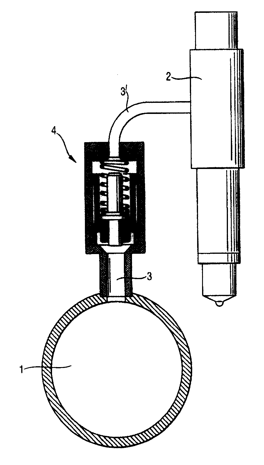
如图1中完全示意地示出的,本发明的关闭阀4可以适合于共轨燃料储存喷射系统。象这样的共轨储存喷射系统是已知的并不在本文更详细地说明。共轨储存喷射系统包括一作为其基本部件的共轨储存器1,其中燃料处于高压作用下以便喷射入发动机,并且该共轨储存器与喷射阀2流动连通。对于配送燃料给每一气缸(未示出)的喷射阀2,从共轨储存器1中配置一燃料通道管3、3’。在操作过程中在该共轨储存器内保持一个压力借以为喷射阀2提供足够的喷射压力。每一喷射阀2包括控制装置(未示出)用以单独控制喷射。在燃料通道管3、3’中设有一关闭阀4,其操作参照图2-5说明如下。As shown fully schematically in Figure 1, the shut-off valve 4 of the present invention may be adapted for a common rail fuel storage injection system. Common rail storage injection systems like this are known and will not be described in more detail here. The common rail accumulator injection system includes as its basic components a common rail accumulator 1 in which fuel is under high pressure for injection into the engine and which is in flow communication with an
图2中示出关闭阀处于其初始状态的情况。关闭阀包括一本体部件5,其中设有圆柱形燃料空间6。燃料所用的一入口连接件7和一出口连接件8适于与燃料空间相连。在本体部件5的燃料空间6中配装有一优选包括一活塞或类似物的致动件9。根据活塞的不同位置,燃料或可以流过关闭阀或可以阻断燃料的流动。关闭阀4还包括还包括一弹簧10,在其作用下活塞结构9处于图1中所示贴着本体部件5的肩部5’的状态。在正常运行的状态下,在各次喷射之间关闭阀4处于图2的位置。Figure 2 shows the shut-off valve in its initial state. The shut-off valve comprises a
当在正常操作过程中喷射阀2开始喷射时,越过关闭阀4,换言之在入口连接件7与出口连接件8之间形成一压差,在这种情况下活塞结构9启动并移动到喷射停止和压差平衡为止。这种情况表示于图3中。在这种情况下被喷射的燃料量等于由活塞结构9在燃料空间6内运动所移动的容积。When the
一辅助致动件即辅助活塞12与活塞结构9相连可移动地布置。活塞结构9包括在燃料空间6的入口连接件7一侧的部段中的区域9’,其限制所述空间6,因此燃料空间的压力作用在所述区域9’上,并且在正常操作时,辅助活塞12随活塞结构9一起移动而这两者之间没有相互移动。An auxiliary actuator, the
在关闭阀4泄漏或其由于某种原因在喷射以后并不闭合的情况下,共用的轨道储存器1的压力将活塞结构9与辅助活塞12一起推到其另一极限位置,如图4中所示。在活塞结构9的这个位置大大限制了进入喷射阀2的流量,因为整个的流量流经一节流孔11。该节流孔将在燃料空间6的活塞结构的不同侧面的部段相互连通。活塞结构9上的压差增大了并在其达到一特定的极限时辅助活塞12相对于活塞结构9移动,并且密封表面13、13’闭合而切断流动,这种情况示于图5中。其中辅助活塞12的密封表面13的相反表面13’与出口连接件8相连地布置。产生这样的操作,使得辅助活塞12包括邻接在燃料室6的入口连接件7一侧的部段中的空间的区域12’,并且该区域小于活塞结构9的相应区域9’,在这种情况下最初活塞结构9和辅助活塞12发生共同的移动并且仅仅在压差超过一定的极限时辅助活塞12才在活塞结构中移动。因此,移动辅助活塞12的压力仅被引导在由其直径决定的所述区域上并且其移动需要比能够使整个活塞结构9移动的压力更大的压力。In the event that the shut-off valve 4 leaks or it does not close after injection for some reason, the pressure of the common rail reservoir 1 pushes the
本发明的关闭阀4在发动机的启动中例如在重燃料应用中操作如下。在启动发动机以前开始燃料循环时,燃料系统的低压侧的压力作用到入口连接件7。在该初始状态时出口连接件8一侧可以是几乎没有压力或甚至充满空气。在下一阶段关闭阀4的活塞结构9移到图4中所示的位置,换言之移到其第二极限位置。可以认为,例如在燃料系统的低压侧的压强约为7巴。关闭阀4的尺寸例如可以确定成使将辅助活塞12移动到图5中的位置所需要的压差为25巴。这意味着,实际上关闭阀4保持开通并且能够充满在出口连接件8一侧的部段和在其后面来自喷射系统的部段,以及平衡入口连接件7与出口连接件8之间的压力。当入口连接件与出口连接件之间的压力已充分平衡时,关闭阀的活塞结构9移到图2中所示的位置并且可以无问题地启动发动机。这样,节流孔11的尺寸可以只根据要求的活塞结构9的返回速度(在发动运行时的正常状态下)来确定。如果在发动机运行时在关闭阀的出口连接件8一侧中有例如管道泄漏,则关闭阀立即闭合。The shut-off valve 4 of the present invention operates in the start-up of the engine, for example in heavy fuel applications, as follows. When starting the fuel cycle before starting the engine, the pressure on the low-pressure side of the fuel system acts on the inlet connection 7 . In this initial state the side of the outlet connection 8 can be almost depressurized or even filled with air. In the next stage the
图6中示出另一关闭阀的实施方案。该实施方案在其他方面相当于图2-5中所示的一个,但将辅助活塞12不同地配置以与活塞结构9本身一起用作为流动关闭装置。在该实施方案中在活塞结构的孔中匹配一螺栓12等,使穿过其中的通道11从其相对于燃料空间6的活塞结构的另一端通向在出口连接件8一侧的部段,并从其相对于燃料空间6的活塞结构的该另一端通向在入口连接件7一侧的部段。现在,如果越过活塞结构9的压差超过一特定的极限,螺栓12移向出口连接件,在这种情况下密封表面13、13’最后彼此贴靠。其中正要发生所述移动。在根据图6的实施方案中辅助活塞的密封表面13的相反表面13’与活塞结构9相连地布置。Another shut-off valve embodiment is shown in FIG. 6 . This embodiment is otherwise equivalent to the one shown in Figures 2-5, but with the
本发明不限于所示的各实施方案,但本发明若干修改在所附权利要求书的范围内是合理的。The invention is not limited to the embodiments shown, but several modifications of the invention are logical within the scope of the appended claims.
Claims (7)
Applications Claiming Priority (2)
| Application Number | Priority Date | Filing Date | Title |
|---|---|---|---|
| FI20011379 | 2001-06-27 | ||
| FI20011379A FI114501B (en) | 2001-06-27 | 2001-06-27 | Power limit valve for fuel system |
Publications (2)
| Publication Number | Publication Date |
|---|---|
| CN1395035A CN1395035A (en) | 2003-02-05 |
| CN100402833C true CN100402833C (en) | 2008-07-16 |
Family
ID=8561514
Family Applications (1)
| Application Number | Title | Priority Date | Filing Date |
|---|---|---|---|
| CNB02123163XA Expired - Lifetime CN100402833C (en) | 2001-06-27 | 2002-06-27 | Fuel system shut-off valve |
Country Status (9)
| Country | Link |
|---|---|
| US (1) | US6953052B2 (en) |
| EP (1) | EP1270931B1 (en) |
| JP (1) | JP4139630B2 (en) |
| KR (1) | KR100815374B1 (en) |
| CN (1) | CN100402833C (en) |
| AT (1) | ATE315723T1 (en) |
| DE (1) | DE60208632T2 (en) |
| FI (1) | FI114501B (en) |
| PL (1) | PL201492B1 (en) |
Families Citing this family (21)
| Publication number | Priority date | Publication date | Assignee | Title |
|---|---|---|---|---|
| FI117643B (en) * | 2003-01-15 | 2006-12-29 | Waertsilae Finland Oy | Arrangements at fuel injection plant |
| DE10344593B4 (en) * | 2003-09-25 | 2015-10-08 | Robert Bosch Gmbh | Backflow throttle valve |
| US7758585B2 (en) | 2005-03-16 | 2010-07-20 | Alcon, Inc. | Pumping chamber for a liquefaction handpiece |
| DE102005023323A1 (en) * | 2005-05-20 | 2006-11-23 | Siemens Ag | Non-return valve for fitting into machine housings has casing, in which valve stem and plate are mounted which are biased towards open position by spring above them |
| KR101100518B1 (en) | 2006-11-06 | 2011-12-29 | 현대중공업 주식회사 | Start prevention device |
| US7849875B2 (en) * | 2007-07-31 | 2010-12-14 | Alcon, Inc. | Check valve |
| US7658179B2 (en) * | 2008-05-28 | 2010-02-09 | Caterpillar Inc. | Fluid leak limiter |
| US7661410B1 (en) * | 2008-08-18 | 2010-02-16 | Caterpillar Inc. | Fluid leak limiter |
| US8291933B2 (en) * | 2008-09-25 | 2012-10-23 | Novartis Ag | Spring-less check valve for a handpiece |
| FI122557B (en) | 2009-04-02 | 2012-03-30 | Waertsilae Finland Oy | Fuel injection arrangement for a piston engine |
| DE102010005101B4 (en) * | 2010-01-20 | 2011-09-01 | Poppe & Potthoff Gmbh | Pressure limiting valve, in particular for limiting the fluid pressure in a manifold of a common rail injection system |
| CA2838001C (en) * | 2010-06-03 | 2018-04-24 | David Mcintosh | Driven guide systems for lifts |
| DK2423498T3 (en) * | 2010-08-26 | 2013-12-09 | Waertsilae Nsd Schweiz Ag | Passive flow control valve |
| DE102011102170B4 (en) | 2011-05-20 | 2024-06-06 | Vitesco Technologies GmbH | Injection device for injecting a fluid |
| AT513158B1 (en) * | 2012-04-10 | 2014-03-15 | Bosch Gmbh Robert | Flow restrictor with ball and throttle |
| KR102215184B1 (en) * | 2014-05-05 | 2021-02-15 | 아스바드 아이엔티, 에스.엘. | Passive depressurisation system for pressurised receptacles in nuclear reactors |
| US20160097362A1 (en) * | 2014-10-06 | 2016-04-07 | Hamilton Sundstrand Corporation | Variable area orifice for an engine |
| KR101800936B1 (en) * | 2014-11-21 | 2017-11-23 | 오엠티 오피신 메카니체 토리노 에스.피.에이. | A fuel flow limiting valve for large internal combustion engines |
| JP6714649B2 (en) * | 2018-07-17 | 2020-06-24 | 住友理工株式会社 | connector |
| CN111448388B (en) * | 2018-07-23 | 2022-04-05 | 住友理工株式会社 | Connector |
| US11346313B2 (en) * | 2020-09-03 | 2022-05-31 | Caterpillar Inc. | Fuel flow limiter assembly having integral fuel filter and fuel system using same |
Citations (6)
| Publication number | Priority date | Publication date | Assignee | Title |
|---|---|---|---|---|
| GB515231A (en) * | 1936-12-12 | 1939-11-29 | Rudolf L Orange | Improvements in or relating to pressure control systems for fuel injection pumps |
| US3780716A (en) * | 1971-02-19 | 1973-12-25 | Cav Ltd | Fuel injection systems |
| GB2126664A (en) * | 1982-09-08 | 1984-03-28 | Lucas Ind Plc | Delivery valve |
| WO1995017594A1 (en) * | 1993-12-23 | 1995-06-29 | L'orange Gmbh | Fuel injection device with high-pressure fuel store |
| US5511528A (en) * | 1991-01-14 | 1996-04-30 | Nippondenso Co., Ltd. | Accumulator type of fuel injection device |
| CN1179197A (en) * | 1996-01-27 | 1998-04-15 | 罗伯特·博施有限公司 | Pressure valve |
Family Cites Families (12)
| Publication number | Priority date | Publication date | Assignee | Title |
|---|---|---|---|---|
| US922578A (en) * | 1909-02-04 | 1909-05-25 | Albert Theadore Gries | Automatic shut-off valve. |
| US2247421A (en) * | 1938-06-18 | 1941-07-01 | Eisemann Magneto Corp | Pressure regulator for fuel injection systems for internal combustion engines |
| DE2103948A1 (en) * | 1971-01-28 | 1972-09-14 | Kupex Ag | Automatic valve |
| JPS5958279A (en) * | 1982-09-08 | 1984-04-03 | ル−カス・インダストリ−ズ・パブリツク・リミテツド・カンパニ− | Delivery valve for fuel injection pump |
| FR2558533B1 (en) * | 1984-01-23 | 1986-06-13 | Renault | SAFETY DEVICE FOR AN INJECTION VALVE OF AN INTERNAL COMBUSTION ENGINE |
| CH684708A5 (en) * | 1991-05-28 | 1994-11-30 | Dusko Maravic | Flow control valve. |
| DE4414242A1 (en) * | 1994-04-23 | 1995-10-26 | Bosch Gmbh Robert | Fuel injection device for internal combustion engines |
| DE19747092B4 (en) | 1997-10-24 | 2005-01-13 | Siemens Ag | Flow limiting device for internal combustion engines |
| DE19860476A1 (en) * | 1998-12-28 | 2000-07-06 | Bosch Gmbh Robert | Fuel injection system |
| JP3521811B2 (en) * | 1999-08-05 | 2004-04-26 | 株式会社デンソー | Safety devices for internal combustion engines |
| DE10015576B4 (en) * | 2000-03-29 | 2014-07-10 | Eurocopter Deutschland Gmbh | Arrangement of a valve in one of a tank vessel to an above the tank vessel arranged internal combustion engine leading fuel delivery line |
| US6374852B1 (en) * | 2000-08-09 | 2002-04-23 | Brightvalve, Llc | Leak arresting valve |
-
2001
- 2001-06-27 FI FI20011379A patent/FI114501B/en not_active IP Right Cessation
-
2002
- 2002-05-28 PL PL354189A patent/PL201492B1/en unknown
- 2002-06-24 US US10/179,759 patent/US6953052B2/en not_active Expired - Lifetime
- 2002-06-25 JP JP2002184779A patent/JP4139630B2/en not_active Expired - Lifetime
- 2002-06-25 EP EP02254416A patent/EP1270931B1/en not_active Expired - Lifetime
- 2002-06-25 AT AT02254416T patent/ATE315723T1/en active
- 2002-06-25 DE DE60208632T patent/DE60208632T2/en not_active Expired - Lifetime
- 2002-06-26 KR KR1020020035871A patent/KR100815374B1/en not_active Expired - Lifetime
- 2002-06-27 CN CNB02123163XA patent/CN100402833C/en not_active Expired - Lifetime
Patent Citations (6)
| Publication number | Priority date | Publication date | Assignee | Title |
|---|---|---|---|---|
| GB515231A (en) * | 1936-12-12 | 1939-11-29 | Rudolf L Orange | Improvements in or relating to pressure control systems for fuel injection pumps |
| US3780716A (en) * | 1971-02-19 | 1973-12-25 | Cav Ltd | Fuel injection systems |
| GB2126664A (en) * | 1982-09-08 | 1984-03-28 | Lucas Ind Plc | Delivery valve |
| US5511528A (en) * | 1991-01-14 | 1996-04-30 | Nippondenso Co., Ltd. | Accumulator type of fuel injection device |
| WO1995017594A1 (en) * | 1993-12-23 | 1995-06-29 | L'orange Gmbh | Fuel injection device with high-pressure fuel store |
| CN1179197A (en) * | 1996-01-27 | 1998-04-15 | 罗伯特·博施有限公司 | Pressure valve |
Also Published As
| Publication number | Publication date |
|---|---|
| EP1270931A3 (en) | 2004-02-11 |
| JP4139630B2 (en) | 2008-08-27 |
| CN1395035A (en) | 2003-02-05 |
| KR100815374B1 (en) | 2008-03-19 |
| FI20011379L (en) | 2002-12-28 |
| JP2003035238A (en) | 2003-02-07 |
| ATE315723T1 (en) | 2006-02-15 |
| DE60208632D1 (en) | 2006-04-06 |
| US6953052B2 (en) | 2005-10-11 |
| FI114501B (en) | 2004-10-29 |
| FI20011379A0 (en) | 2001-06-27 |
| US20030000581A1 (en) | 2003-01-02 |
| PL354189A1 (en) | 2002-12-30 |
| KR20030004056A (en) | 2003-01-14 |
| PL201492B1 (en) | 2009-04-30 |
| EP1270931A2 (en) | 2003-01-02 |
| EP1270931B1 (en) | 2006-01-11 |
| DE60208632T2 (en) | 2006-08-24 |
Similar Documents
| Publication | Publication Date | Title |
|---|---|---|
| CN100402833C (en) | Fuel system shut-off valve | |
| US9506382B2 (en) | Variable valve actuator | |
| US20100116910A1 (en) | Ball valve with reduced erosion behavior | |
| US7690588B2 (en) | Fuel injector nozzle with flow restricting device | |
| US6843464B2 (en) | Valve for controlling liquids | |
| CN1462337A (en) | Fuel injection valve for internal-combustion engine | |
| JPH07189850A (en) | Fuel injection device for internal combustion engine | |
| CN103180601B (en) | Pressure regulator valve | |
| JP2003512565A (en) | High pressure fuel injector with hydraulically controlled control spool | |
| CN205477982U (en) | Air intake system and internal -combustion engine | |
| JP2002533614A (en) | Fuel injection device | |
| CN110469430A (en) | Valve assembly for regulating gas pressure and fuel system with valve assembly | |
| JP2004517254A (en) | Injection valve | |
| JP2003513196A (en) | Injector with hydraulically preloaded pressure transducer for fuel injection systems of internal combustion engines | |
| EP1388666B1 (en) | Fuel injection device | |
| JP2004521262A (en) | Fuel injector with injection path shaping by switchable throttle element | |
| JP2003511623A (en) | Injector for a fuel injection system used in an internal combustion engine having a nozzle needle protruding into a valve control chamber | |
| JP4253659B2 (en) | Valve for controlling connections provided in a high-pressure liquid system, in particular a high-pressure liquid system of a fuel injection device for an internal combustion engine | |
| JP4714268B2 (en) | Fuel injection device for direct fuel injection internal combustion engine | |
| JP2004517263A (en) | Injection valve | |
| JP2004532955A (en) | Fuel injector with variable control room pressure load | |
| JP2004527685A (en) | Fuel injector booster | |
| CN104454277A (en) | Valve assembly for fuel supply system and the fuel supply system | |
| JP2004521263A (en) | Fuel injector with two-way valve control | |
| JP4447595B2 (en) | Fuel injection device for internal combustion engine |
Legal Events
| Date | Code | Title | Description |
|---|---|---|---|
| C06 | Publication | ||
| PB01 | Publication | ||
| C10 | Entry into substantive examination | ||
| SE01 | Entry into force of request for substantive examination | ||
| C14 | Grant of patent or utility model | ||
| GR01 | Patent grant | ||
| CX01 | Expiry of patent term |
Granted publication date: 20080716 |
|
| CX01 | Expiry of patent term |