CN100398304C - Seamless body and manufacturing method thereof - Google Patents
Seamless body and manufacturing method thereof Download PDFInfo
- Publication number
- CN100398304C CN100398304C CNB018185401A CN01818540A CN100398304C CN 100398304 C CN100398304 C CN 100398304C CN B018185401 A CNB018185401 A CN B018185401A CN 01818540 A CN01818540 A CN 01818540A CN 100398304 C CN100398304 C CN 100398304C
- Authority
- CN
- China
- Prior art keywords
- light
- outer cylinder
- metal level
- sensitive medium
- inner periphery
- Prior art date
- Legal status (The legal status is an assumption and is not a legal conclusion. Google has not performed a legal analysis and makes no representation as to the accuracy of the status listed.)
- Expired - Lifetime
Links
Images


Classifications
-
- B—PERFORMING OPERATIONS; TRANSPORTING
- B29—WORKING OF PLASTICS; WORKING OF SUBSTANCES IN A PLASTIC STATE IN GENERAL
- B29D—PRODUCING PARTICULAR ARTICLES FROM PLASTICS OR FROM SUBSTANCES IN A PLASTIC STATE
- B29D11/00—Producing optical elements, e.g. lenses or prisms
-
- B—PERFORMING OPERATIONS; TRANSPORTING
- B29—WORKING OF PLASTICS; WORKING OF SUBSTANCES IN A PLASTIC STATE IN GENERAL
- B29D—PRODUCING PARTICULAR ARTICLES FROM PLASTICS OR FROM SUBSTANCES IN A PLASTIC STATE
- B29D17/00—Producing carriers of records containing fine grooves or impressions, e.g. disc records for needle playback, cylinder records; Producing record discs from master stencils
-
- B—PERFORMING OPERATIONS; TRANSPORTING
- B29—WORKING OF PLASTICS; WORKING OF SUBSTANCES IN A PLASTIC STATE IN GENERAL
- B29C—SHAPING OR JOINING OF PLASTICS; SHAPING OF MATERIAL IN A PLASTIC STATE, NOT OTHERWISE PROVIDED FOR; AFTER-TREATMENT OF THE SHAPED PRODUCTS, e.g. REPAIRING
- B29C33/00—Moulds or cores; Details thereof or accessories therefor
- B29C33/38—Moulds or cores; Details thereof or accessories therefor characterised by the material or the manufacturing process
- B29C33/3842—Manufacturing moulds, e.g. shaping the mould surface by machining
- B29C33/3857—Manufacturing moulds, e.g. shaping the mould surface by machining by making impressions of one or more parts of models, e.g. shaped articles and including possible subsequent assembly of the parts
- B29C33/3892—Preparation of the model, e.g. by assembling parts
-
- B—PERFORMING OPERATIONS; TRANSPORTING
- B29—WORKING OF PLASTICS; WORKING OF SUBSTANCES IN A PLASTIC STATE IN GENERAL
- B29C—SHAPING OR JOINING OF PLASTICS; SHAPING OF MATERIAL IN A PLASTIC STATE, NOT OTHERWISE PROVIDED FOR; AFTER-TREATMENT OF THE SHAPED PRODUCTS, e.g. REPAIRING
- B29C39/00—Shaping by casting, i.e. introducing the moulding material into a mould or between confining surfaces without significant moulding pressure; Apparatus therefor
- B29C39/02—Shaping by casting, i.e. introducing the moulding material into a mould or between confining surfaces without significant moulding pressure; Apparatus therefor for making articles of definite length, i.e. discrete articles
- B29C39/028—Shaping by casting, i.e. introducing the moulding material into a mould or between confining surfaces without significant moulding pressure; Apparatus therefor for making articles of definite length, i.e. discrete articles having an axis of symmetry
-
- B—PERFORMING OPERATIONS; TRANSPORTING
- B29—WORKING OF PLASTICS; WORKING OF SUBSTANCES IN A PLASTIC STATE IN GENERAL
- B29C—SHAPING OR JOINING OF PLASTICS; SHAPING OF MATERIAL IN A PLASTIC STATE, NOT OTHERWISE PROVIDED FOR; AFTER-TREATMENT OF THE SHAPED PRODUCTS, e.g. REPAIRING
- B29C41/00—Shaping by coating a mould, core or other substrate, i.e. by depositing material and stripping-off the shaped article; Apparatus therefor
- B29C41/02—Shaping by coating a mould, core or other substrate, i.e. by depositing material and stripping-off the shaped article; Apparatus therefor for making articles of definite length, i.e. discrete articles
- B29C41/08—Coating a former, core or other substrate by spraying or fluidisation, e.g. spraying powder
- B29C41/085—Coating a former, core or other substrate by spraying or fluidisation, e.g. spraying powder by rotating the former around its axis of symmetry
-
- B—PERFORMING OPERATIONS; TRANSPORTING
- B29—WORKING OF PLASTICS; WORKING OF SUBSTANCES IN A PLASTIC STATE IN GENERAL
- B29C—SHAPING OR JOINING OF PLASTICS; SHAPING OF MATERIAL IN A PLASTIC STATE, NOT OTHERWISE PROVIDED FOR; AFTER-TREATMENT OF THE SHAPED PRODUCTS, e.g. REPAIRING
- B29C41/00—Shaping by coating a mould, core or other substrate, i.e. by depositing material and stripping-off the shaped article; Apparatus therefor
- B29C41/02—Shaping by coating a mould, core or other substrate, i.e. by depositing material and stripping-off the shaped article; Apparatus therefor for making articles of definite length, i.e. discrete articles
- B29C41/12—Spreading-out the material on a substrate, e.g. on the surface of a liquid
-
- G—PHYSICS
- G02—OPTICS
- G02B—OPTICAL ELEMENTS, SYSTEMS OR APPARATUS
- G02B5/00—Optical elements other than lenses
- G02B5/02—Diffusing elements; Afocal elements
- G02B5/0205—Diffusing elements; Afocal elements characterised by the diffusing properties
- G02B5/0252—Diffusing elements; Afocal elements characterised by the diffusing properties using holographic or diffractive means
-
- B—PERFORMING OPERATIONS; TRANSPORTING
- B29—WORKING OF PLASTICS; WORKING OF SUBSTANCES IN A PLASTIC STATE IN GENERAL
- B29C—SHAPING OR JOINING OF PLASTICS; SHAPING OF MATERIAL IN A PLASTIC STATE, NOT OTHERWISE PROVIDED FOR; AFTER-TREATMENT OF THE SHAPED PRODUCTS, e.g. REPAIRING
- B29C35/00—Heating, cooling or curing, e.g. crosslinking or vulcanising; Apparatus therefor
- B29C35/02—Heating or curing, e.g. crosslinking or vulcanizing during moulding, e.g. in a mould
- B29C35/08—Heating or curing, e.g. crosslinking or vulcanizing during moulding, e.g. in a mould by wave energy or particle radiation
- B29C35/0805—Heating or curing, e.g. crosslinking or vulcanizing during moulding, e.g. in a mould by wave energy or particle radiation using electromagnetic radiation
- B29C2035/0838—Heating or curing, e.g. crosslinking or vulcanizing during moulding, e.g. in a mould by wave energy or particle radiation using electromagnetic radiation using laser
-
- B—PERFORMING OPERATIONS; TRANSPORTING
- B29—WORKING OF PLASTICS; WORKING OF SUBSTANCES IN A PLASTIC STATE IN GENERAL
- B29K—INDEXING SCHEME ASSOCIATED WITH SUBCLASSES B29B, B29C OR B29D, RELATING TO MOULDING MATERIALS OR TO MATERIALS FOR MOULDS, REINFORCEMENTS, FILLERS OR PREFORMED PARTS, e.g. INSERTS
- B29K2021/00—Use of unspecified rubbers as moulding material
-
- B—PERFORMING OPERATIONS; TRANSPORTING
- B29—WORKING OF PLASTICS; WORKING OF SUBSTANCES IN A PLASTIC STATE IN GENERAL
- B29L—INDEXING SCHEME ASSOCIATED WITH SUBCLASS B29C, RELATING TO PARTICULAR ARTICLES
- B29L2023/00—Tubular articles
-
- B—PERFORMING OPERATIONS; TRANSPORTING
- B29—WORKING OF PLASTICS; WORKING OF SUBSTANCES IN A PLASTIC STATE IN GENERAL
- B29L—INDEXING SCHEME ASSOCIATED WITH SUBCLASS B29C, RELATING TO PARTICULAR ARTICLES
- B29L2031/00—Other particular articles
- B29L2031/757—Moulds, cores, dies
-
- G—PHYSICS
- G02—OPTICS
- G02B—OPTICAL ELEMENTS, SYSTEMS OR APPARATUS
- G02B6/00—Light guides; Structural details of arrangements comprising light guides and other optical elements, e.g. couplings
- G02B6/0001—Light guides; Structural details of arrangements comprising light guides and other optical elements, e.g. couplings specially adapted for lighting devices or systems
- G02B6/0011—Light guides; Structural details of arrangements comprising light guides and other optical elements, e.g. couplings specially adapted for lighting devices or systems the light guides being planar or of plate-like form
- G02B6/0033—Means for improving the coupling-out of light from the light guide
- G02B6/005—Means for improving the coupling-out of light from the light guide provided by one optical element, or plurality thereof, placed on the light output side of the light guide
- G02B6/0051—Diffusing sheet or layer
-
- G—PHYSICS
- G02—OPTICS
- G02B—OPTICAL ELEMENTS, SYSTEMS OR APPARATUS
- G02B6/00—Light guides; Structural details of arrangements comprising light guides and other optical elements, e.g. couplings
- G02B6/0001—Light guides; Structural details of arrangements comprising light guides and other optical elements, e.g. couplings specially adapted for lighting devices or systems
- G02B6/0011—Light guides; Structural details of arrangements comprising light guides and other optical elements, e.g. couplings specially adapted for lighting devices or systems the light guides being planar or of plate-like form
- G02B6/0065—Manufacturing aspects; Material aspects
-
- G—PHYSICS
- G02—OPTICS
- G02F—OPTICAL DEVICES OR ARRANGEMENTS FOR THE CONTROL OF LIGHT BY MODIFICATION OF THE OPTICAL PROPERTIES OF THE MEDIA OF THE ELEMENTS INVOLVED THEREIN; NON-LINEAR OPTICS; FREQUENCY-CHANGING OF LIGHT; OPTICAL LOGIC ELEMENTS; OPTICAL ANALOGUE/DIGITAL CONVERTERS
- G02F1/00—Devices or arrangements for the control of the intensity, colour, phase, polarisation or direction of light arriving from an independent light source, e.g. switching, gating or modulating; Non-linear optics
- G02F1/01—Devices or arrangements for the control of the intensity, colour, phase, polarisation or direction of light arriving from an independent light source, e.g. switching, gating or modulating; Non-linear optics for the control of the intensity, phase, polarisation or colour
- G02F1/13—Devices or arrangements for the control of the intensity, colour, phase, polarisation or direction of light arriving from an independent light source, e.g. switching, gating or modulating; Non-linear optics for the control of the intensity, phase, polarisation or colour based on liquid crystals, e.g. single liquid crystal display cells
- G02F1/133—Constructional arrangements; Operation of liquid crystal cells; Circuit arrangements
- G02F1/1333—Constructional arrangements; Manufacturing methods
- G02F1/1335—Structural association of cells with optical devices, e.g. polarisers or reflectors
- G02F1/1336—Illuminating devices
- G02F1/133615—Edge-illuminating devices, i.e. illuminating from the side
-
- Y—GENERAL TAGGING OF NEW TECHNOLOGICAL DEVELOPMENTS; GENERAL TAGGING OF CROSS-SECTIONAL TECHNOLOGIES SPANNING OVER SEVERAL SECTIONS OF THE IPC; TECHNICAL SUBJECTS COVERED BY FORMER USPC CROSS-REFERENCE ART COLLECTIONS [XRACs] AND DIGESTS
- Y10—TECHNICAL SUBJECTS COVERED BY FORMER USPC
- Y10T—TECHNICAL SUBJECTS COVERED BY FORMER US CLASSIFICATION
- Y10T428/00—Stock material or miscellaneous articles
- Y10T428/12—All metal or with adjacent metals
- Y10T428/12493—Composite; i.e., plural, adjacent, spatially distinct metal components [e.g., layers, joint, etc.]
- Y10T428/12771—Transition metal-base component
- Y10T428/12861—Group VIII or IB metal-base component
- Y10T428/12944—Ni-base component
-
- Y—GENERAL TAGGING OF NEW TECHNOLOGICAL DEVELOPMENTS; GENERAL TAGGING OF CROSS-SECTIONAL TECHNOLOGIES SPANNING OVER SEVERAL SECTIONS OF THE IPC; TECHNICAL SUBJECTS COVERED BY FORMER USPC CROSS-REFERENCE ART COLLECTIONS [XRACs] AND DIGESTS
- Y10—TECHNICAL SUBJECTS COVERED BY FORMER USPC
- Y10T—TECHNICAL SUBJECTS COVERED BY FORMER US CLASSIFICATION
- Y10T428/00—Stock material or miscellaneous articles
- Y10T428/12—All metal or with adjacent metals
- Y10T428/12993—Surface feature [e.g., rough, mirror]
-
- Y—GENERAL TAGGING OF NEW TECHNOLOGICAL DEVELOPMENTS; GENERAL TAGGING OF CROSS-SECTIONAL TECHNOLOGIES SPANNING OVER SEVERAL SECTIONS OF THE IPC; TECHNICAL SUBJECTS COVERED BY FORMER USPC CROSS-REFERENCE ART COLLECTIONS [XRACs] AND DIGESTS
- Y10—TECHNICAL SUBJECTS COVERED BY FORMER USPC
- Y10T—TECHNICAL SUBJECTS COVERED BY FORMER US CLASSIFICATION
- Y10T428/00—Stock material or miscellaneous articles
- Y10T428/13—Hollow or container type article [e.g., tube, vase, etc.]
- Y10T428/1352—Polymer or resin containing [i.e., natural or synthetic]
- Y10T428/139—Open-ended, self-supporting conduit, cylinder, or tube-type article
- Y10T428/1393—Multilayer [continuous layer]
-
- Y—GENERAL TAGGING OF NEW TECHNOLOGICAL DEVELOPMENTS; GENERAL TAGGING OF CROSS-SECTIONAL TECHNOLOGIES SPANNING OVER SEVERAL SECTIONS OF THE IPC; TECHNICAL SUBJECTS COVERED BY FORMER USPC CROSS-REFERENCE ART COLLECTIONS [XRACs] AND DIGESTS
- Y10—TECHNICAL SUBJECTS COVERED BY FORMER USPC
- Y10T—TECHNICAL SUBJECTS COVERED BY FORMER US CLASSIFICATION
- Y10T428/00—Stock material or miscellaneous articles
- Y10T428/24—Structurally defined web or sheet [e.g., overall dimension, etc.]
- Y10T428/24942—Structurally defined web or sheet [e.g., overall dimension, etc.] including components having same physical characteristic in differing degree
- Y10T428/2495—Thickness [relative or absolute]
- Y10T428/24967—Absolute thicknesses specified
-
- Y—GENERAL TAGGING OF NEW TECHNOLOGICAL DEVELOPMENTS; GENERAL TAGGING OF CROSS-SECTIONAL TECHNOLOGIES SPANNING OVER SEVERAL SECTIONS OF THE IPC; TECHNICAL SUBJECTS COVERED BY FORMER USPC CROSS-REFERENCE ART COLLECTIONS [XRACs] AND DIGESTS
- Y10—TECHNICAL SUBJECTS COVERED BY FORMER USPC
- Y10T—TECHNICAL SUBJECTS COVERED BY FORMER US CLASSIFICATION
- Y10T428/00—Stock material or miscellaneous articles
- Y10T428/26—Web or sheet containing structurally defined element or component, the element or component having a specified physical dimension
Landscapes
- Engineering & Computer Science (AREA)
- Mechanical Engineering (AREA)
- Physics & Mathematics (AREA)
- Manufacturing & Machinery (AREA)
- General Physics & Mathematics (AREA)
- Ophthalmology & Optometry (AREA)
- Health & Medical Sciences (AREA)
- Optics & Photonics (AREA)
- Optical Elements Other Than Lenses (AREA)
- Diffracting Gratings Or Hologram Optical Elements (AREA)
- Moulds For Moulding Plastics Or The Like (AREA)
- Shaping Of Tube Ends By Bending Or Straightening (AREA)
- Moulding By Coating Moulds (AREA)
- Light Guides In General And Applications Therefor (AREA)
- Exposure And Positioning Against Photoresist Photosensitive Materials (AREA)
Abstract
中空的、圆柱状无缝金属主体(604),用来按预先选定的长度和宽带来制造无缝漫射片。本发明的另一方面包含一个中空圆柱无缝的可翻面弹性主体(402)及其制造方法,以及在感光介质上实现可变散射片记录的装置和方法。
A hollow, cylindrical, seamless metal body (604) is used to manufacture a seamless diffuser sheet according to a predetermined length and width. Another aspect of the invention includes a hollow, cylindrical, seamless, flip-up elastic body (402) and a method for manufacturing the same, as well as an apparatus and method for realizing variable diffuser sheet recording on a photosensitive medium.
Description
发明背景Background of the invention
1、发明领域1. Field of invention
本发明包括多个方面,涉及光线成形漫射片领域,并涉及无缝主体及其制造方法,以及漫射片膜的缝隙复制,即,形成无断点或断痕的连续光线成形涂层。The invention includes various aspects and relates to the field of light-shaping diffusers, and to seamless bodies and methods of manufacture thereof, as well as slot replication of diffuser films, ie to form a continuous light-shaping coating without discontinuities or breaks.
特别是,本发明的第一方面涉及一种中空的、圆柱状、无缝的、可翻面的、带有一体化微表面结构的弹性主体,并包括这种主体的制造方法。本发明的第二方面涉及一种与本发明第一方面相关的可变漫射片记录装置及其制造方法。本发明的第三方面涉及一种无缝的、上面制有一体化的微表面结构的圆柱状金属主体及其制造方法,它与本发明的其它两个方面有关。本发明的第四方面涉及根据上述三方面的无缝(连续膜)生产。In particular, the first aspect of the present invention relates to a hollow, cylindrical, seamless, reversible elastic body with an integrated microsurface structure, and includes a method of manufacturing such a body. The second aspect of the present invention relates to a variable diffusion sheet recording device related to the first aspect of the present invention and its manufacturing method. A third aspect of the present invention relates to a seamless cylindrical metal body provided with an integrated microsurface structure and a method of making the same, which is related to the other two aspects of the present invention. A fourth aspect of the present invention relates to seamless (continuous film) production according to the above three aspects.
2、相关技术说明2. Related technical description
漫射片主体被用来生产大量的光线成形漫射片,这些漫射片可以对从中传输的光线产生预期的光学影响。Diffuser masters are used to produce a large number of light shaping diffusers that create the desired optical impact on the light transmitted through them.
例如,全息光线成形漫射片,是包括“全息记录的”随机化的表面结构漫射片,这种表面结构上的漫射片具有高传输效率、高光线成形质量、和使光线均匀化的能力;这种全息光成形漫射片可以从美国加利福尼亚的托兰斯物理光学公司(“POC”)买到,其商标为LSD![]()
![]()
另外关于这方面,授予Jannson等人(被转让给了POC)的美国专利No.5,365,354在此并入作为参考,其披露了一种具有一体制成的光线成形漫射片微结构的漫射片,其中的漫射片是由可以买到的感光介质(例如商业光致抗蚀剂)加工而成,其中感光介质中记录有预先选定的斑纹图案。Also in this regard, U.S. Patent No. 5,365,354 to Jannson et al. (assigned to POC), which is hereby incorporated by reference, discloses a diffuser having integrally formed light-shaping diffuser microstructures , where the diffuser is fabricated from a commercially available photosensitive medium (such as a commercial photoresist) in which a preselected speckle pattern is recorded.
在美国专利No.5,534,386和No.5,609,939(两者都被授予Petersen等人,并被转让给了POC)中披露了其它的光线成形漫射片,在此也并入作为参考。可以利用Petersen的两种专利所传授的方法,在感光介质上加工并复制出内部和/或表面微结构,感光介质包括例如传统的光致抗蚀剂。微结构可以以高效、均匀和可控制的方式对光进行散射,而采用先前的方法就不能做到这一点。Other light shaping diffusers are disclosed in US Patent Nos. 5,534,386 and 5,609,939 (both issued to Petersen et al. and assigned to POC), also incorporated herein by reference. The methods taught by the two Petersen patents can be used to fabricate and reproduce internal and/or surface microstructures on photosensitive media, such as conventional photoresists. The microstructures can scatter light in an efficient, uniform and controllable manner that has not been possible with previous methods.
在授予Perilloux等人的美国专利No.5,151,917中披露了一种方法,根据这种现有方法,微结构被说明为形成一层具有亚结构的层压片。在应用中,我们发现这种层压结构会带来一些问题。例如,某些与层压结构有关的问题包括:层之间分离;层间界面表面上的传输损失(由于反射和/或折射);或由粘结的光学层与用来粘结光学层的光学级环氧树脂胶之间的折射率值的差异或者环氧树脂胶中的小气泡所产生的问题。According to a prior art method disclosed in US Patent No. 5,151,917 to Perilloux et al., microstructures are described to form a laminate with substructures. In application, we found that this laminated structure would cause some problems. For example, some of the problems associated with laminated structures include: separation between layers; transmission loss (due to reflection and/or refraction) at interface surfaces between layers; Problems caused by differences in refractive index values between optical grade epoxies or small air bubbles in the epoxies.
优选地,通过采用相干光在传统的感光材料中一体地形成微结构,从而制造光线成形漫射片。另外关于这方面,根据分配角的不同,这种光线成形漫射片可以达到85%至92%的传输率,波长在365纳米(“nm”)到1600nm之间。光线成形漫射片结构的低反向散射在本质上具有抗反射特性,可以利用原本会因菲涅耳衰减而损失的光线。Preferably, the light-shaping diffuser is fabricated by integrally forming microstructures in a conventional photosensitive material using coherent light. Also in this regard, the light-shaping diffuser can achieve a transmission of 85% to 92%, depending on the distribution angle, at wavelengths between 365 nanometers ("nm") and 1600 nm. The low backscatter of the light-shaping diffuser structure is inherently anti-reflective, allowing light that would otherwise be lost to Fresnel attenuation to be utilized.
以下将简要介绍LSD![]()
![]()
![]()
![]()
![]()
![]()
光线成形性质使得LSD![]()
![]()
![]()
![]()
使光线均匀化的能力很重要,这是因为许多光源都会产生“热点”和光线分配形式不均匀的问题,这些光源包括发光二极管(“LED”)光源、灯丝基光源、电弧基光源以及光纤和激光光源。LSD![]()
![]()
然而,用于制造光线成形漫射片的传统主体通常是平面的并且尺寸有限。目前生产用在荧光屏的光线成形漫射片的制造过程会造成这些主体的边缘重叠、毗连、或彼此相邻,进而在漫射片上产生称为“缝”的相应边缘图案;这是人们所不希望的,因为它会产生“干扰”区域,对通过漫射片上“缝”部分的光线传播能力产生不利的影响。还有,当在长的连续塑料片上制成大量的光线成形漫射片,并卷起以备存储时,接缝就压在卷绕着的其它漫射片上,因而会损坏那些漫射片。另外,在许多大型高清晰度显示器的应用中是无法容忍接缝的,这些应用包括军事训练、空战模拟器、FFA实时交通控制显示器和商业显示器。However, conventional bodies used to make light-shaping diffusers are generally planar and limited in size. The current manufacturing process for producing light-shaping diffusers used in phosphor screens causes the edges of these bodies to overlap, adjoin, or adjoin each other, creating corresponding edge patterns on the diffuser called "slits"; Desirable because it creates "noise" areas that adversely affect the ability to transmit light through the "slit" portions of the diffuser. Also, when a large number of light shaping diffusers are made on a long continuous sheet of plastic and rolled for storage, the seam presses against the other diffusers that are rolled, thereby damaging those diffusers. Additionally, seams cannot be tolerated in many large high-definition display applications, including military training, air combat simulators, FFA real-time traffic control displays, and commercial displays.
通过最近的改进,这种漫射片上的边缘“接缝”已经被减小成一根很细的线。然而,在漫射片中,即使是一根非常细的线,也会对目前应用的宽屏幕漫射片的性能产生不利的影响;这些宽屏幕的宽度可达30或40英尺宽,甚至达到100英尺或更宽,就像现在全世界著名的娱乐领域所期待的那样。With recent improvements, the edge "seam" on this diffuser has been reduced to a very thin line. However, even a very thin line in a diffuser can adversely affect the performance of the wide screen diffusers currently in use; these wide screens can be as wide as 30 or 40 feet wide, or even as wide as 100 feet or wider, as is now expected in world-renowned entertainment arenas.
因此,就有必要制造出一种无缝主体,以便用来生产无缝的LSD![]()
![]()
发明概述Summary of the invention
本发明解决了与漫射片有关的一系列问题,及与之相关的漫射片主体边缘“干扰”图案问题;简而言之,本发明是关于一种无缝主体及其制造方法。The present invention solves a number of problems associated with diffusers, and the associated "interfering" pattern at the edge of the diffuser body; in short, the invention is about a seamless body and method of making it.
根据本发明第一方面,一种制造单件圆柱无缝金属主体的方法,包含以下步骤:According to a first aspect of the present invention, a method of manufacturing a single-piece cylindrical seamless metal body comprising the steps of:
(1)在圆柱元件上沿径向安装整体的弹性材料中空圆柱层,所述中空圆柱层的外圆柱表面上具有一体化的光线成形漫射片表面,其中所述光线成形漫射片表面限定有预先选定的横向和纵向排列的几何形状,这些几何形状具有预先选定的径向尺寸;(1) An integral hollow cylindrical layer of elastic material is installed radially on the cylindrical element, and the outer cylindrical surface of the hollow cylindrical layer has an integrated light-shaping diffuser surface, wherein the light-shaped diffuser surface defines There are pre-selected transverse and longitudinal arrangements of geometric shapes with pre-selected radial dimensions;
(2)使所述整体的弹性材料层的外圆柱表面与第一金属涂层紧密接触,其中的第一金属涂层限定有外圆柱表面和内圆柱表面,所述内圆柱表面与整体的弹性材料层的外圆柱表面紧密接触,其中第一金属涂层的数量和径向尺寸与整体弹性材料层的外圆柱表面相关,结果使得光线成形漫射片表面得到充分的复制,复制是从整体的弹性材料层的外圆柱表面到第一金属涂层的外圆柱表面;(2) bringing the outer cylindrical surface of the integral layer of elastic material into close contact with a first metal coating, wherein the first metal coating defines an outer cylindrical surface and an inner cylindrical surface, the inner cylindrical surface is in contact with the integral elastic The outer cylindrical surface of the material layer is in close contact, wherein the number and radial dimensions of the first metal coating are related to the outer cylindrical surface of the integral elastic material layer, resulting in an adequate replication of the surface of the light-shaping diffuser from the overall the outer cylindrical surface of the layer of elastomeric material to the outer cylindrical surface of the first metal coating;
(3)使第一金属涂层的外圆柱表面与第二金属层紧密接触,其中的第二金属层是可以钝化的,其中第二金属层限定有外圆柱表面和内圆柱表面,所述内圆柱表面与第一金属涂层的外圆柱表面紧密接触,结果使得光线成形漫射片表面沿径向得到充分的复制,复制是从第一金属涂层的外圆柱表面到可钝化的第二金属层的内圆柱表面;(3) making the outer cylindrical surface of the first metal coating closely contact with the second metal layer, wherein the second metal layer can be passivated, wherein the second metal layer defines an outer cylindrical surface and an inner cylindrical surface, said The inner cylindrical surface is in intimate contact with the outer cylindrical surface of the first metallic coating such that the surface of the light shaping diffuser is substantially replicated radially from the outer cylindrical surface of the first metallic coating to the passivable second cylindrical surface. the inner cylindrical surface of the second metal layer;
(4)将圆柱元件和整体弹性材料层从第二金属层上分离,因此光线成形漫射片表面沿径向得到了充分的复制,复制是从第一金属涂层的外圆柱表面到可钝化的第二金属层的内圆柱表面;(4) Separating the cylindrical element and the integral layer of elastic material from the second metal layer, so that the surface of the light-shaping diffuser is fully replicated in the radial direction, from the outer cylindrical surface of the first metal coating to the bluntable the inner cylindrical surface of the second metallic layer;
(5)对第二金属层的内圆柱表面的光线成形漫射片表面进行钝化;(5) passivating the surface of the light-shaping diffuser on the inner cylindrical surface of the second metal layer;
(6)使第二金属层的内圆周的光线成形漫射片表面与第三金属层紧密接触,其中所述第三金属层呈圆柱状,并限定有内圆柱表面和外圆柱表面,所述外圆柱表面与第二金属层的内圆周的光线成形漫射片表面紧密接触,结果使得第二金属层内圆周的光线成形漫射片表面沿径向充分地复制到圆柱状第三金属层的外圆柱表面上;(6) The surface of the light-shaping diffuser on the inner circumference of the second metal layer is in close contact with the third metal layer, wherein the third metal layer is cylindrical and defines an inner cylindrical surface and an outer cylindrical surface, the The outer cylindrical surface is in intimate contact with the light-shaping diffuser surface of the inner circumference of the second metal layer such that the surface of the light-shaping diffuser at the inner circumference of the second metal layer is substantially replicated radially to the surface of the cylindrical third metal layer. on the outer cylindrical surface;
(7)把钝化的第二金属层从圆柱状的第三金属层上分离,因此光线成形漫射片表面沿径向得到了充分的复制,复制是从第二金属层的内圆柱表面到圆柱状的第三金属层的外圆柱表面。(7) Separate the passivated second metal layer from the cylindrical third metal layer, so that the surface of the light-shaping diffuser is fully replicated in the radial direction, from the inner cylindrical surface of the second metal layer to the The outer cylindrical surface of the cylindrical third metal layer.
根据本发明第二方面,在第一方面中,整体的中空圆柱弹性材料层的径向厚度大约为1/16英寸到1/8英寸。According to a second aspect of the invention, in the first aspect, the integral hollow cylindrical layer of elastic material has a radial thickness of about 1/16 inch to 1/8 inch.
根据本发明第三方面,在第二方面中,第一金属涂层是银。According to a third aspect of the invention, in the second aspect, the first metallic coating is silver.
根据本发明第四方面,在第一方面中,第二金属层是镀镍层。According to a fourth aspect of the present invention, in the first aspect, the second metal layer is a nickel plating layer.
根据本发明第五方面,在第四方面中,镀镍层纵向伸展的、整体的、中空的和圆柱状的,其径向厚度大约为5/1000英寸至10/1000英寸。According to a fifth aspect of the present invention, in the fourth aspect, the nickel plating layer is longitudinally extending, integral, hollow and cylindrical, and has a radial thickness of about 5/1000 to 10/1000 of an inch.
根据本发明第六方面,在第一方面中,第三金属层是镀镍层。According to a sixth aspect of the present invention, in the first aspect, the third metal layer is a nickel plating layer.
根据本发明第七方面,在第六方面中,镀镍层纵向伸展的、整体的,其径向厚度大约为0.020英寸。According to a seventh aspect of the present invention, in the sixth aspect, the nickel plating layer is longitudinally elongated and integral having a radial thickness of about 0.020 inches.
根据本发明第八方面,一种制造单件体圆柱无缝主体的方法,这种方法包含以下步骤:According to an eighth aspect of the present invention, a method of manufacturing a one-piece cylindrical seamless body, the method comprising the steps of:
(1)在圆柱元件的外周表面部分上沿径向安装整体的弹性材料中空圆柱层,所述中空圆柱层限定了外圆柱表面并在外圆柱表面上具有一体化的光线成形漫射片表面,其中所述光线成形漫射片表面限定有预先选定的斑纹图案和结果的横向和纵向排列的几何形状,这些几何形状具有预先选定的径向尺寸;(1) radially mounting an integral hollow cylindrical layer of elastic material on a portion of the outer peripheral surface of the cylindrical member, said hollow cylindrical layer defining an outer cylindrical surface and having an integrated light-shaping diffuser surface on the outer cylindrical surface, wherein said light-shaping diffuser surface defines a preselected speckle pattern and resulting laterally and longitudinally aligned geometries having preselected radial dimensions;
(2)使所述整体的弹性材料层的外圆柱表面与第一金属有效数量的涂层紧密接触,其中的第一金属涂层限定有外圆柱表面和内圆柱表面,所述内圆柱表面与中空圆柱弹性材料层的外圆柱表面紧密接触,其中第一金属涂层的数量和径向尺寸与中空圆柱弹性材料层的外圆柱表面相关,结果使得光线成形漫射片表面得到充分的复制,复制是从中空圆柱弹性材料层的外圆柱表面到第一金属涂层的外圆柱表面;(2) bringing the outer cylindrical surface of the unitary layer of elastomeric material into intimate contact with an effective amount of a coating of a first metal, wherein the first metal coating defines an outer cylindrical surface and an inner cylindrical surface, the inner cylindrical surface being in contact with The outer cylindrical surface of the hollow cylindrical elastic material layer is in close contact, wherein the number and radial size of the first metal coating are related to the outer cylindrical surface of the hollow cylindrical elastic material layer, so that the surface of the light shaping diffuser is fully replicated, replicated is from the outer cylindrical surface of the hollow cylindrical elastic material layer to the outer cylindrical surface of the first metal coating;
(3)使第一金属涂层的外圆柱表面与第二金属层紧密接触,其中的第二金属层是可以钝化的,其中第二金属层限定有外圆柱表面和内圆柱表面,所述内圆柱表面与第一金属涂层的外圆柱表面紧密接触,结果使得光线成形漫射片表面沿径向得到充分的复制,复制是从第一金属涂层的外圆柱表面到可钝化的第二金属层的内圆柱表面;(3) making the outer cylindrical surface of the first metal coating closely contact with the second metal layer, wherein the second metal layer can be passivated, wherein the second metal layer defines an outer cylindrical surface and an inner cylindrical surface, said The inner cylindrical surface is in intimate contact with the outer cylindrical surface of the first metallic coating such that the surface of the light shaping diffuser is substantially replicated radially from the outer cylindrical surface of the first metallic coating to the passivable second cylindrical surface. the inner cylindrical surface of the second metal layer;
(4)将圆柱元件和中空圆柱弹性材料层从第二金属层上分离,因此光线成形漫射片表面沿径向得到了充分的复制,复制是从第一金属涂层的外圆柱表面到可钝化的第二金属层的内圆柱表面;(4) The cylindrical element and the hollow cylindrical layer of elastic material are separated from the second metal layer, so that the surface of the light-shaping diffuser is fully replicated in the radial direction, from the outer cylindrical surface of the first metal coating to the available the inner cylindrical surface of the passivated second metal layer;
(5)对第二金属层的内圆柱表面的光线成形漫射片表面进行钝化;(5) passivating the surface of the light-shaping diffuser on the inner cylindrical surface of the second metal layer;
(6)使第二金属层的内圆周的光线成形漫射片表面与第三金属层紧密接触,其中所述第三金属层呈圆柱状,并限定有有内圆柱表面和外圆柱表面,所述外圆柱表面与第二金属层的内圆周的光线成形漫射片表面紧密接触,结果使得第二金属层内圆周的光线成形漫射片表面沿径向充分地复制到圆柱状第三金属层的外圆柱表面上;(6) Make the surface of the light-shaping diffuser on the inner circumference of the second metal layer be in close contact with the third metal layer, wherein the third metal layer is cylindrical and defines an inner cylindrical surface and an outer cylindrical surface, so The outer cylindrical surface is in intimate contact with the light-shaping diffuser surface of the inner circumference of the second metal layer, so that the surface of the light-shaping diffuser at the inner circumference of the second metal layer is substantially replicated radially to the cylindrical third metal layer on the outer cylindrical surface of
(7)把钝化的第二金属层从圆柱状的第三金属层上分离,因此光线成形漫射片表面沿径向得到了充分的复制,复制是从第二金属层的内圆柱表面到圆柱状的第三金属层的外圆柱表面。(7) Separate the passivated second metal layer from the cylindrical third metal layer, so that the surface of the light-shaping diffuser is fully replicated in the radial direction, from the inner cylindrical surface of the second metal layer to the The outer cylindrical surface of the cylindrical third metal layer.
根据本发明第九方面,在第八方面中,整体的中空圆柱弹性材料层的径向厚度大约为1/16英寸至1/8英寸。According to a ninth aspect of the invention, in the eighth aspect, the integral hollow cylindrical layer of elastic material has a radial thickness of about 1/16 inch to 1/8 inch.
根据本发明第十方面,在第九方面中,第一金属涂层是银。According to a tenth aspect of the present invention, in the ninth aspect, the first metal coating is silver.
根据本发明第十一方面,在第八方面中,第二金属层是镀镍层。According to the eleventh aspect of the present invention, in the eighth aspect, the second metal layer is a nickel plating layer.
根据本发明第十二方面,在第十一方面中,镀镍层是整体的、纵向伸展的、中空的和圆柱状的,其中镀镍层径向厚度大约为5/1000英寸至10/1000英寸。According to a twelfth aspect of the present invention, in the eleventh aspect, the nickel plating layer is integral, longitudinally extending, hollow and cylindrical, wherein the nickel plating layer has a radial thickness of about 5/1000 to 10/1000 of an inch inch.
根据本发明第十三方面,在第八方面中,第三金属层是镀镍层。According to a thirteenth aspect of the present invention, in the eighth aspect, the third metal layer is a nickel plating layer.
根据本发明第十四方面,在第十三方面中,镀镍层是整体的、纵向伸展的,沿半径方向的厚度大约为0.020英寸。According to a fourteenth aspect of the present invention, in the thirteenth aspect, the nickel plating layer is unitary, longitudinally extending, and has a radial thickness of about 0.020 inches.
根据本发明第十五方面,一种制造单件体的中空圆柱可翻面弹性主体的方法,包括以下步骤:According to the fifteenth aspect of the present invention, a method for manufacturing a single-piece hollow cylindrical elastic body that can be turned over includes the following steps:
(1)把有效量的液态可固化感光介质涂覆到长圆柱元件的外圆柱表面上,所述长圆柱元件限定有纵向轴线并可以绕此轴线转动,使圆柱体元件绕其纵向轴线转动,以便大体沿长度和外圆柱表面形成径向尺寸大体均匀的无缝可固化的感光介质层;(1) applying an effective amount of liquid curable photosensitive medium to an outer cylindrical surface of an elongated cylindrical member, said elongated cylindrical member defining a longitudinal axis and rotatable about this axis, causing the cylindrical member to rotate about its longitudinal axis, to form a seamless curable photosensitive medium layer of substantially uniform radial dimension along its length and outer cylindrical surface;
(2)使长圆柱元件上的感光介质层固化;(2) curing the photosensitive medium layer on the long cylindrical element;
(3)使大体沿长度和外圆柱表面的固化的感光介质层对具有预先选定的斑纹图案的相干光源进行曝光,并使圆柱体元件绕其轴线转动,以便使感光介质曝光,并大体沿着圆柱元件上感光介质的长度和外圆柱表面,以不规则的方式在曝光后的感光介质上产生相应的预定斑纹图案,因此上面曝光后的感光介质能够在随后进行显影;(3) exposing the cured photosensitive medium layer substantially along the length and outer cylindrical surface to a coherent light source having a preselected speckle pattern, and rotating the cylindrical member about its axis to expose the photosensitive medium and generally along the Depending on the length of the photosensitive medium on the cylindrical element and the outer cylindrical surface, a corresponding predetermined speckle pattern is produced on the exposed photosensitive medium in an irregular manner, so that the above exposed photosensitive medium can be subsequently developed;
(4)对曝光过的感光介质进行显影,以便把感光介质上不规则的曝光区域定形为介质中的物理微结构;(4) developing the exposed photosensitive medium, so that the irregular exposure area on the photosensitive medium is shaped into a physical microstructure in the medium;
(5)沿着显影后的感光材料的长度和外圆柱表面涂覆一种有效量的可固化弹性液体并固化这种弹性液体,以便产生具有预定径向尺寸的长的中空圆柱弹性元件,它与感光材料中记录的斑纹图案紧密接触,从而在弹性元件中产生无缝的光线成形漫射片表面,此处弹性元件与斑纹图案紧密接触,其中的中空圆柱元件是可翻面的;(5) coating an effective amount of a curable elastic liquid along the length of the developed photosensitive material and the outer cylindrical surface and curing the elastic liquid to produce a long hollow cylindrical elastic member having a predetermined radial dimension, which In close contact with the speckle pattern recorded in the photosensitive material, thereby producing a seamless light-shaping diffuser surface in the elastic element, where the elastic element is in intimate contact with the speckle pattern, wherein the hollow cylindrical element is reversible;
(6)把可翻转的中空圆柱弹性元件从记录有斑纹图案的显影后的感光材料上分开,因此可翻面的中空圆柱弹性元件大体沿着其长度和内圆柱表面上具有无缝光线成形漫射片表面;(6) Separate the reversible hollow cylindrical elastic member from the developed photosensitive material on which the speckle pattern is recorded, so that the reversible hollow cylindrical elastic member generally has a seamless light-shaping diffuse along its length and on the inner cylindrical surface. film surface;
(7)翻转中空圆柱弹性元件,以便大体沿长度和外圆柱表面呈现出无缝光线成形漫射片表面,这样就生产出了中空圆柱弹性主体。(7) Inverting the hollow cylindrical elastic member so as to present a seamless light-shaping diffuser surface generally along the length and outer cylindrical surface, thus producing the hollow cylindrical elastic body.
根据本发明第十六方面,在第十五方面中,感光介质的径向厚度大约为1微米至100微米。According to the sixteenth aspect of the present invention, in the fifteenth aspect, the radial thickness of the photosensitive medium is about 1 μm to 100 μm.
根据本发明第十七方面,在第十五方面中,感光介质的径向厚度大约为35微米。According to a seventeenth aspect of the present invention, in the fifteenth aspect, the photosensitive medium has a radial thickness of about 35 micrometers.
根据本发明第十八方面,在第十五方面中,感光介质的固化是通过在提高的温度下烘烤上述介质而实现的,烘烤时间大约为四十分钟到两个小时。According to the eighteenth aspect of the present invention, in the fifteenth aspect, the photosensitive medium is cured by baking the above-mentioned medium at an elevated temperature, and the baking time is about forty minutes to two hours.
根据本发明第十九方面,在第十五方面中,感光介质的固化是通过在大约90℃下烘烤上述介质而实现的,烘烤时间大约为一个小时到两个小时。According to the nineteenth aspect of the present invention, in the fifteenth aspect, the photosensitive medium is cured by baking the above-mentioned medium at about 90° C., and the baking time is about one hour to two hours.
根据本发明第二十方面,在第十五方面中,感光介质的固化是通过在大约65℃下烘烤上述介质而实现的,烘烤时间大约为一个小时。According to the twentieth aspect of the present invention, in the fifteenth aspect, the photosensitive medium is cured by baking the above-mentioned medium at about 65° C., and the baking time is about one hour.
根据本发明第二十一方面,在第十五方面中,曝光后的感光介质的显影,是通过使上述介质与有效量的10%重量比例的显影剂水溶液相接触来实现的,接触时间范围从大约30秒到大约1分钟。According to the twenty-first aspect of the present invention, in the fifteenth aspect, the development of the exposed photosensitive medium is realized by contacting the above-mentioned medium with an effective amount of a 10% by weight aqueous developer solution, and the contact time ranges from From about 30 seconds to about 1 minute.
根据本发明第二十二方面,在第十五方面中,弹性液体的固化是通过使上述弹性液体在室温下经过大约二十四小时而实现的。According to the twenty-second aspect of the present invention, in the fifteenth aspect, the elastic liquid is cured by allowing the above-mentioned elastic liquid to pass for about twenty-four hours at room temperature.
根据本发明第二十三方面,在第十五方面中,感光介质的中空圆柱弹性元件的径向厚度大约为1/16英寸到1/8英寸。According to a twenty-third aspect of the present invention, in the fifteenth aspect, the hollow cylindrical elastic member of the photosensitive medium has a radial thickness of about 1/16 inch to 1/8 inch.
根据本发明第二十四方面,一种制造单件体的中空圆柱可翻面弹性主体的方法,包括以下步骤:According to the twenty-fourth aspect of the present invention, a method for manufacturing a single-piece hollow cylindrical reversible elastic body includes the following steps:
(1)把有效量的液态可固化感光介质涂覆到长圆柱元件的外圆柱表面上,所述长圆柱元件限定有纵向轴线并可以绕此轴线转动,使圆柱体元件绕其纵向轴线转动,以便大体沿长度和外圆柱表面形成径向尺寸大体均匀的无缝可固化的感光介质层;(1) applying an effective amount of liquid curable photosensitive medium to an outer cylindrical surface of an elongated cylindrical member, said elongated cylindrical member defining a longitudinal axis and rotatable about this axis, causing the cylindrical member to rotate about its longitudinal axis, to form a seamless curable photosensitive medium layer of substantially uniform radial dimension along its length and outer cylindrical surface;
(2)使长圆柱元件上的感光介质层固化;(2) curing the photosensitive medium layer on the long cylindrical element;
(3)使大体沿长度和外圆柱表面的固化的感光介质层对具有预先选定的斑纹图案的相干光源进行曝光,并使圆柱体元件绕其轴线转动,以便使感光介质曝光,并大体沿着圆柱元件上感光介质的长度和外圆柱表面,以不规则的方式在曝光后的感光介质上产生相应的预定斑纹图案,因此上面曝光后的感光介质能够在随后进行显影;(3) exposing the cured photosensitive medium layer substantially along the length and outer cylindrical surface to a coherent light source having a preselected speckle pattern, and rotating the cylindrical member about its axis to expose the photosensitive medium and generally along the Depending on the length of the photosensitive medium on the cylindrical element and the outer cylindrical surface, a corresponding predetermined speckle pattern is produced on the exposed photosensitive medium in an irregular manner, so that the above exposed photosensitive medium can be subsequently developed;
(4)对曝光过的感光介质进行显影,以便把感光介质上不规则的曝光区域定形为介质中的物理微结构;(4) developing the exposed photosensitive medium, so that the irregular exposure area on the photosensitive medium is shaped into a physical microstructure in the medium;
(5)沿着显影后的感光材料的长度和外圆柱表面涂覆一种有效量的可固化弹性液体并固化这种弹性液体,以便产生具有预定径向尺寸的长的中空圆柱弹性元件,它与感光材料中记录的斑纹图案紧密接触,从而在弹性元件中产生无缝的光线成形漫射片表面,此处弹性元件与斑纹图案紧密接触,其中的中空圆柱元件是可翻面的;(5) coating an effective amount of a curable elastic liquid along the length of the developed photosensitive material and the outer cylindrical surface and curing the elastic liquid to produce a long hollow cylindrical elastic member having a predetermined radial dimension, which In close contact with the speckle pattern recorded in the photosensitive material, thereby producing a seamless light-shaping diffuser surface in the elastic element, where the elastic element is in intimate contact with the speckle pattern, wherein the hollow cylindrical element is reversible;
(6)把可翻转的中空圆柱弹性元件从记录有斑纹图案的显影后的感光材料上分开,因此可翻面的中空圆柱弹性元件大体沿着其长度和内圆柱表面上具有无缝光线成形漫射片表面;(6) Separate the reversible hollow cylindrical elastic member from the developed photosensitive material on which the speckle pattern is recorded, so that the reversible hollow cylindrical elastic member generally has a seamless light-shaping diffuse along its length and on the inner cylindrical surface. film surface;
(7)翻转中空圆柱弹性元件,以便大体沿长度和外圆柱表面呈现出无缝光线成形漫射片表面,这样就生产出了中空圆柱弹性主体。(7) Inverting the hollow cylindrical elastic member so as to present a seamless light-shaping diffuser surface generally along the length and outer cylindrical surface, thus producing the hollow cylindrical elastic body.
根据本发明第二十五方面,在第二十四方面中,感光介质径向厚度大约为1微米到大约100微米。According to a twenty-fifth aspect of the present invention, in the twenty-fourth aspect, the photosensitive medium has a radial thickness of about 1 micrometer to about 100 micrometers.
根据本发明第二十六方面,在第二十四方面中,感光介质径向大约为35微米。According to a twenty-sixth aspect of the present invention, in the twenty-fourth aspect, the photosensitive medium has a diameter of about 35 microns in a radial direction.
根据本发明第二十七方面,在第二十四方面中,感光介质的固化,是通过在提高的温度下对上述介质进行烘烤来实现的,烘烤时间大约从四十分钟到大约两个小时。According to the twenty-seventh aspect of the present invention, in the twenty-fourth aspect, the curing of the photosensitive medium is achieved by baking the above-mentioned medium at an elevated temperature, and the baking time is from about forty minutes to about two Hours.
根据本发明第二十八方面,在第二十四方面中,感光介质的固化,是通过在大约90℃下对上述介质进行烘烤来实现的,烘烤时间大约从一小时到大约两个小时。According to the twenty-eighth aspect of the present invention, in the twenty-fourth aspect, the curing of the photosensitive medium is realized by baking the above-mentioned medium at about 90° C., and the baking time is from about one hour to about two hours. Hour.
根据本发明第二十九方面,在第二十四方面中,感光介质的固化,是通过在大约65℃下对上述介质进行烘烤来实现的,烘烤时间大约为一小时。According to the twenty-ninth aspect of the present invention, in the twenty-fourth aspect, the photosensitive medium is cured by baking the above-mentioned medium at about 65° C., and the baking time is about one hour.
根据本发明第三十方面,在第二十四方面中,曝光后的感光介质的显影,是通过使上述介质与一种适量的10%重量比例的显影剂水溶液相接触来实现的,接触时间范围从大约30秒到大约1分钟。According to the thirtieth aspect of the present invention, in the twenty-fourth aspect, the development of the exposed photosensitive medium is realized by making the above-mentioned medium contact with an appropriate amount of 10% by weight of an aqueous developer solution, and the contact time is Ranges from about 30 seconds to about 1 minute.
根据本发明第三十一方面,在第二十四方面中,弹性液体的固化,是通过使上述弹性液体在室温下经过大约二十四小时而实现的。According to the thirty-first aspect of the present invention, in the twenty-fourth aspect, the elastic liquid is cured by allowing the above elastic liquid to stand at room temperature for about twenty-four hours.
根据本发明第三十二方面,在第二十四方面中,中空圆柱体元件径向厚度为大约1/16到大约1/8英寸。According to a thirty-second aspect of the invention, in the twenty-fourth aspect, the hollow cylindrical member has a radial thickness of about 1/16 to about 1/8 inch.
附图说明 Description of drawings
参照以下说明的典型而非限定性的具体实施例,并结合附图,本领域普通技术人员可以更清楚地了解构成本发明的优点和特征,其中包括以上概述的本发明的各方面细节,以及本发明提出的典型机构的构造和工作原理;这些具体实施例和附图构成了本专利说明书的一部分,在这些视图中,同样的附图标记对应相同的元件,其中:With reference to the typical non-limiting specific embodiments described below, in conjunction with the accompanying drawings, those skilled in the art can more clearly understand the advantages and features that constitute the present invention, including the details of the various aspects of the present invention outlined above, and The structure and working principle of the typical mechanism proposed by the present invention; these specific embodiments and accompanying drawings constitute a part of this patent specification, and in these views, the same reference numerals correspond to the same elements, wherein:
图1是一种带有长圆柱状可旋转元件的机构的侧视图,这种机构用来生产本发明的弹性主体;Figure 1 is a side view of a mechanism with an elongated cylindrical rotatable element for producing the elastic body of the present invention;
图2是相对于图1后续的、时序相关的侧视图,其说明了把适量的可买到的可固化的液态感光介质(例如普通的光致抗蚀剂)涂覆在图1中所示的可转动元件的圆周外表面上的优选方法;FIG. 2 is a subsequent, time-sequential side view relative to FIG. 1 illustrating the application of an appropriate amount of a commercially available curable liquid photosensitive medium (such as a conventional photoresist) to the surface shown in FIG. 1. preferred method on the peripheral outer surface of the rotatable element;
图3也是一个带有局部剖面的侧视图,它说明了在完成图2中的涂覆步骤之后,使感光材料变成可转动元件的圆周外表面上的基本无缝而均匀的涂层的优选方法;Figure 3 is also a side view with a partial section illustrating the preferred method for rendering the photosensitive material into a substantially seamless and uniform coating on the peripheral outer surface of the rotatable member after the coating step in Figure 2 is completed method;
图4是一个侧视正视图,部分为剖视图,部分为示意图,它说明了另一种可以在外圆周外表面上均匀地涂覆一层无缝的可固化的液态感光介质的优选方法;这个外圆周外表面位于图1-3中的另一个实施例的长圆柱体元件上;Figure 4 is a side elevational view, partly in section and partly schematic, illustrating another preferred method for uniformly coating a seamless curable liquid photosensitive medium on the outer surface of the outer circumference; The peripheral outer surface is on the elongated cylindrical element of another embodiment in Figs. 1-3;
图5是一个用来固化感光介质的装置的透视图;Figure 5 is a perspective view of an apparatus for curing a photosensitive medium;
图6是一个侧面正视图,它说明了一种在固化过的感光介质上进行可变散射片记录的优选装置和方法;Figure 6 is a side elevational view illustrating a preferred apparatus and method for variable-scattering sheet recording on cured photosensitive media;
图7是另一个示意图,其与图6相比放大了比例,说明了本发明的某些原理;Figure 7 is another schematic diagram, on an enlarged scale compared to Figure 6, illustrating some principles of the present invention;
图8是一个详细视图,其相对于图7做了进一步放大,用来说明优选物镜装置上的优选元件,所述装置与本发明的上述几个方面之一相关;Figure 8 is a detailed view, further enlarged relative to Figure 7, illustrating preferred elements of a preferred objective lens arrangement associated with one of the above-mentioned aspects of the invention;
图9是一个透视图,其相对于图7略有放大,说明了图6和图7中边沿上的一个元件的优选孔径的几何尺寸,这个元件也是本发明上述方面的另一个元件;Figure 9 is a perspective view, slightly enlarged with respect to Figure 7, illustrating the preferred aperture geometry of an element on the edge of Figures 6 and 7, which element is also another element of the above aspect of the invention;
图10是侧面正视示意图6的俯视平面视图;Fig. 10 is a top plan view of schematic side view 6;
图11是侧面正视示意图6的俯视平面视图的另一个具体实施例,用来说明上述在感光介质中记录可变散射片的装置和方法的特征,它是通过选择性地改变图7至图9中所示的元件之间的间隔关系来实现的(从而使用上面说明的相关原理),它提供了与固化过的感光介质的曝光相关的细节,如图6、图10和图11中所说明的那样;Figure 11 is another specific embodiment of the top plan view of the side elevation schematic diagram 6, which is used to illustrate the features of the above-mentioned device and method for recording variable scattering sheets in a photosensitive medium, by selectively changing Figures 7 to 9 achieved by the spacing relationship between the elements shown in (thus using the relevant principles explained above), which provides details related to the exposure of the cured photosensitive medium, as illustrated in Figures 6, 10 and 11 like
图12是一个带有局部剖视的侧面正视图,它说明了一个大小可以容纳圆柱体元件的中空容器,所述圆柱体元件的外圆柱表面上带有固化过的曝光过的感光介质,图中还说明了圆柱体元件正在被插入到中空容器之中;Figure 12 is a side elevational view, partially in section, illustrating a hollow container sized to accommodate a cylindrical member with cured, exposed photosensitive medium on its outer cylindrical surface, FIG. also shows that the cylindrical element is being inserted into the hollow container;
图13也是一个带有局部剖视的侧面正视图,它说明了一种用来对曝光过的感光介质进行显影的优选方法,在这种方法中,图中所说明的圆柱体元件(如图1-3中所示)的外圆柱面上带有曝光过的感光介质(如图6、图10和图11所示),它是图12中“插入”步骤的后续步骤;Figure 13 is also a side elevational view, partially in section, illustrating a preferred method for developing an exposed photosensitive medium in which the illustrated cylindrical member (Fig. 1-3) has an exposed photosensitive medium (as shown in Figure 6, Figure 10 and Figure 11) on the outer cylindrical surface, which is a subsequent step of the "insert" step in Figure 12;
图14是一个带有局部剖视的侧面正视图,它说明了一种把可固化的弹性液体均匀地涂覆在曝光过的感光介质的外圆柱表面上的优选方法,它是在图12和13中说明的感光介质的显影方法完成之后进行的;Figure 14 is a side elevational view, partially in section, illustrating a preferred method of uniformly coating the outer cylindrical surface of an exposed photosensitive medium with a curable elastomeric liquid, as shown in Figures 12 and After the development method of the photosensitive medium described in 13 is completed;
图15是一个带有局部剖视的侧面正视图,它说明了图14所示的把可固化的弹性液体均匀地涂覆在曝光并显影后的弹性介质上的方法的随后步骤;Figure 15 is a side elevational view, partially in section, illustrating the subsequent steps of the method of uniformly coating the exposed and developed elastomeric medium with the curable elastomeric liquid shown in Figure 14;
图16是一个侧面正视图,它说明了把可固化的弹性液体均匀地涂覆在显影后的感光介质的外圆柱表面上的优选方法的完成情况,通过这种方法,可以制造出由可固化弹性材料制成的长的中空圆柱体(具有大体均匀的壁厚);Figure 16 is a side elevational view illustrating the implementation of the preferred method of uniformly coating the outer cylindrical surface of the developed photosensitive medium with a curable elastomeric liquid by which a curable elastomeric liquid Elongated hollow cylinders (with generally uniform wall thickness) of elastic material;
图17是一个带有局部剖视的侧面正视图,用来说明在完成了所述弹性材料的固化之后,把刚固化的弹性元件(其外观呈套筒状)从制成的感光介质上剥离下来的优选方法,它是通过把固化后的中空圆柱体弹性材料进行反转而实现的;Figure 17 is a side elevational view with a partial cutaway, used to illustrate that after the curing of the elastic material is completed, the freshly cured elastic member (which has a sleeve-like appearance) is peeled off from the produced photosensitive medium The optimal method down, it is to realize by reversing the hollow cylinder elastic material after solidification;
图18是一个底部元件的透视图,它是另一种具体实施例或替代装置上的一个元件,这种替代装置被用于另一种具体实施例或替代方法以便制造出弹性元件(如图14-17所示);Fig. 18 is a perspective view of a base member, which is a member on another embodiment or alternative device, which is used in another embodiment or alternative method to make the elastic member (as shown in FIG. 14-17);
图19是一个盘状元件的透视图,这个盘状元件可以安装在图18所示的底座上;Figure 19 is a perspective view of a disc-shaped element which can be mounted on the base shown in Figure 18;
图20是一个装配后的透视图,其比例相对于图18和19略有缩小,它说明了一个安装在盘状元件上的实心圆柱体元件,其又安装在底座(图18和19)上;其中所示的实心圆柱体元件是带有与外圆柱表面形成一体的无缝光线成形漫射片表面图案的主体;它是图6、10和11中所述的中空圆柱体元件的另一种具体实施例;Figure 20 is an assembled perspective view, on a slightly reduced scale relative to Figures 18 and 19, which illustrates a solid cylindrical element mounted on a disc-shaped element, which in turn is mounted on a base (Figures 18 and 19) ; the solid cylindrical element shown therein is a body with a seamless light-shaping diffuser surface pattern integral with the outer cylindrical surface; it is an alternative to the hollow cylindrical element described in Figures 6, 10 and 11 A specific embodiment;
图21是另一个装配后的透视图,它带有局部剖面,它说明了中空圆柱体的塑模部分,塑模部分连接成环状环绕在图20所示的实心圆柱体元件;Figure 21 is another assembled perspective view, with partial section, illustrating the molded portion of the hollow cylinder connected in a ring around the solid cylindrical element shown in Figure 20;
图22是图21中所示组件的局部平面视图,它说明了图21中所示的连接在一起的圆柱体塑模部分与其所围绕的图20中所示的实心圆柱体元件之间的间隙(或环状间隔);Figure 22 is a fragmentary plan view of the assembly shown in Figure 21 illustrating the gap between the connected cylindrical molded sections shown in Figure 21 and the solid cylindrical elements shown in Figure 20 that they surround (or ring interval);
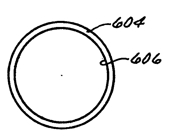
图23是一个侧面正视剖面图,它说明了一个中空圆柱体元件和弹性主体(通过图14-17中所示的方法制成),在固化和翻转之后,在所述的弹性体元件/中空圆柱体元件的外圆柱表面上形成无缝光线成形漫射片图案;Figure 23 is a side elevational cross-sectional view illustrating a hollow cylindrical element and elastomeric body (made by the method shown in Figures 14-17), after curing and inversion, within the elastomeric element/hollow a seamless light-shaping diffuser pattern formed on the outer cylindrical surface of the cylindrical element;
图23A是经过大比例放大的示意图,说明了在光线下显现的斑纹,所述光线用于在弹性体套筒上记录光线成形漫射片的图案,它与固化的弹性主体(通过图14-17中的方法制造)的外圆柱表面制成一体,其中的斑纹是使用圆柱透镜产生的,根据了图7-9中所述的可变散射片记录装置和制造方法(包括原理);Figure 23A is a schematic, greatly enlarged scale illustration of the mottling that appears under light used to record a pattern of light-shaping diffuser on an elastomeric sleeve, which is combined with a cured elastomeric body (via Figure 14- 17), the outer cylindrical surface of which is made into one body, the speckles therein are produced using a cylindrical lens, according to the variable scattering sheet recording device and manufacturing method (including principles) described in FIGS. 7-9;
图23B是经过大比例放大的示意图,说明了在光线下显现的斑纹,所述光线用于在弹性体套筒上记录光线成形漫射片的图案,它与固化的弹性主体(通过图14-17中的方法制造)的外圆柱表面做成一体,其中的斑纹是利用椭圆透镜产生的,根据了图7-9中所述的可变散射片记录装置和制造过程(包括原理);Figure 23B is a schematic, greatly enlarged scale illustrating the speckle that appears under light used to record the pattern of a light-shaping diffuser on an elastomeric sleeve in contact with a cured elastomeric body (via Figure 14- 17), the outer cylindrical surface is made into one, and the speckle therein is produced by using an elliptical lens, according to the variable scattering sheet recording device and the manufacturing process (including the principle) described in Fig. 7-9;
图23-2是图23中所述的侧面正视图的另一个具体实施例。FIG. 23-2 is another embodiment of the side elevational view depicted in FIG. 23 .
图24是弹性体元件/中空圆柱体元件组件(如图23所示)的端视图,其中的中空圆柱体具有一定的长度尺寸(图23)和外径(图24)尺寸,使得弹性体套筒的相应长度和内径足以为光线成形漫射片表面图案提供支撑结构;Figure 24 is an end view of the elastomeric element/hollow cylindrical element assembly (as shown in Figure 23), wherein the hollow cylinder has length dimensions (Figure 23) and outer diameter (Figure 24) dimensions such that the elastomeric sleeve The corresponding length and inner diameter of the barrel is sufficient to provide a support structure for the light-shaping diffuser surface pattern;
图24-2是图24中所述端视图的另一个具体实施例。FIG. 24-2 is another specific embodiment of the end view shown in FIG. 24 .
图25是一个侧面正视剖面图,它说明了弹性元件的外圆柱表面上的由优选材料制成的其它层,结果使整个组件形成一个多层管状复合体,其中的光线成形漫射片表面被夹在所述的复合体层之间;Figure 25 is a side elevational cross-sectional view illustrating additional layers of preferred materials on the outer cylindrical surface of the resilient member, resulting in the overall assembly forming a multilayer tubular composite in which the light-shaping diffuser surface is covered by sandwiched between said composite layers;
图26是图25中所示的多层复合体的端视图;Figure 26 is an end view of the multilayer composite shown in Figure 25;
图27是一个侧面正视剖面图,它说明了在把其它层去掉后图25和26中复合体的最外层,其中在剩下的管状层的内圆柱表面上就形成了无缝的一体化的光线成形漫射片表面;Figure 27 is a side elevation sectional view illustrating the outermost layer of the composite of Figures 25 and 26 after the other layers have been removed, wherein a seamless integration is formed on the inner cylindrical surface of the remaining tubular layer The surface of the light-shaping diffuser;
图28是图27所示剩下的管状层的端视图;Figure 28 is an end view of the remaining tubular layer shown in Figure 27;
图29是一个侧面正视剖面图,它说明了图27和28中所示的剩下的管状层(即中空圆柱体),其中包括附加的圆柱层,如图所示这个附加层形成在所剩下管状层的内圆柱表面上;Figure 29 is a side elevational cross-sectional view illustrating the remaining tubular layer (i.e., hollow cylinder) shown in Figures 27 and 28, including an additional cylindrical layer formed over the remaining layer as shown. on the inner cylindrical surface of the lower tubular layer;
图29-2是图29中所述的侧面正视图的另一个具体实施例。FIG. 29-2 is another embodiment of the side elevational view depicted in FIG. 29. FIG.
图30是图29中所示的多层管状复合体的一个端视图;Figure 30 is an end view of the multilayer tubular composite shown in Figure 29;
图30-2是图30所述的端视图的另一个具体实施例。FIG. 30-2 is another specific embodiment of the end view described in FIG. 30 .
图31是一个侧面正视剖面图,它说明了在剥离了外圆周层后图29和30中所述的内圆周层,其中在所述这样的中空圆柱体外表面上就形成了无缝而一体化的光线成形漫射片表面;Figure 31 is a side elevational sectional view illustrating the inner peripheral layer of Figures 29 and 30 after the outer peripheral layer has been peeled away, wherein a seamless and integral surface is formed on the outer surface of such a hollow cylinder. The surface of the light-shaping diffuser;
图32是图31中的中空圆柱体元件的端视图;和Figure 32 is an end view of the hollow cylindrical element in Figure 31; and
图33是一个透视图,它说明了一个长的图31和32中所述中空圆柱体元件的另一个具体实施例,中空圆柱体元件安装在传统的可转动元件上,与本发明的一种优选工业应用相关。Fig. 33 is a perspective view illustrating another specific embodiment of a long hollow cylindrical member described in Figs. Preferably relevant for industrial applications.
优选实施例说明Description of preferred embodiments
请参看图1-3,图中说明了一种方法和装置,用来把适当的可固化的液态感光材料(例如可以买到的光致抗蚀剂)均匀地涂覆到长的可旋转的圆柱体元件上。图中说明了与这个装置相关的底座100,它上面安装着相对的支架102、104。这个装置还包括一个安装在支架102、104之间的长的中空管106(或管状件),它通过一个曲柄108可以绕着轴A-A转动,如图1中所示。Referring to Figures 1-3, a method and apparatus are illustrated for uniformly coating a suitable curable liquid photosensitive material (such as a commercially available photoresist) onto a long rotatable on the cylindrical element. Illustrated in connection with this device is a base 100 on which opposing
一种优选的中空管106是由可以买到的光滑玻璃(例如一般的窗玻璃)制成。中空管106的另一种具体实施例,可以通过足够光滑的民用塑料制成,例如三聚氰胺、聚碳酸酯、聚苯乙烯、聚氯乙烯,或合适的商用丙烯酸的塑料,例如有机玻璃。A preferred
一种把可固化的液态感光介质110(例如光致抗蚀剂)涂覆在中空管106(优选是玻璃)上的优选方法是,用手把感光介质110沿着中空玻璃管106的整个长度倾注,如图2所示;然后转动曲柄108,直至中空管106的整个外圆柱表面都被涂上一层均匀的光致抗蚀剂。这种“涂覆”操作优选要进行三次,在相邻两次涂覆之间保留大约四十分钟的空气干燥时间(在室温下),最终使得三个分离的感光材料涂覆层变成一个可固化的液态感光介质110的均匀涂覆层。A preferred method of coating curable liquid photosensitive medium 110 (such as photoresist) on hollow tube 106 (preferably glass) is to hand-pass
在完成了“三次涂覆”步骤之后,感光介质110在沿半径方向上的厚度范围大约在1微米到100微米之间。感光介质110在沿半径方向上的优选厚度大约为35微米。After the "three-time coating" step is completed, the thickness of the
图4所示的是另一种装置和方法,用来把可固化的液态感光介质110涂覆在另一个长圆柱元件106A的外圆柱表面上,从而形成一个均匀涂覆的圆周层;长圆柱元件106A是一个实心圆柱体。What Fig. 4 shows is another kind of device and method, is used for curable liquid
如图4所示,平台114、泵116和驱动机构118安装在底板112上。图中所示的圆柱体106A安装在一个转盘120上,120可以绕着轴B-B转动。As shown in FIG. 4 ,
在驱动机构118与转盘120之间连接了一种常规的动力传动机构122,以便驱动120绕着轴B-B转动。传动机构122被用来从驱动机构118到转盘120之间传递动力,以驱动圆柱体元件106A绕着轴线B-B转动,如图4所示。A conventional power transmission mechanism 122 is connected between the
仍参照图4,图中说明了一个通过导管126与泵116相连接的喷嘴124。喷嘴124本身及其安装位置的配置优选能够沿圆柱体元件106A表面的整个长度提供传统流体(例如可固化的液态感光介质110)。为此,装在槽128中的可固化的液态感光介质110通过导管130输送到泵116中。Still referring to FIG. 4 , there is illustrated a nozzle 124 connected to the
可以通过烘烤来实现液态感光介质110的固化。例如,图5中说明了一种常见的烤炉132,可以将上面带有一个均匀的感光材料层110的实心圆柱体106A(未示出)或长的中空管106(见图1-3)插入其中,以便对上述介质110进行所需要的固化。为实现预期的固化,可以在提高的温度(例如100℃)下对感光介质110进行烘烤,烘烤时间为40分钟至2小时。更优选地,在90℃下对感光介质110进行1小时至2.5小时的烘烤,来固化感光介质110。更优选地,在60℃下对感光介质110进行1至3小时的烘烤,来固化感光介质110。The curing of the liquid
可变漫射片有一些传统的用途,例如,用在光导管中或液晶显示器中。例如,象用于便携式电脑上液晶显示器(“LCD”)这样的平板显示器通常带有背光系统,以便照亮液晶平板显示器。传统背光系统的重要要求是,在显示板的整个表面上提供足够均匀且足够强度的光线分布,显示板通常为平板。为达到这两个要求,目前的背光系统中通常带有一个或多个光导管,以便把光能从光源引到LCD板上。对于普通的散射背光系统,有必要在系统中引入一个或多个可变漫射片元件,可变化的漫射片元件可以沿着一个或多个普通光导管的一个表面安装,以便把入射到它上面的光线散射到一个输出平面上,以便达到预期的标准。输出平面可以用一种常规的方式耦合至目前的LCD板,以便把光线耦合到LCD板上并通过LCD板。通过引入可变漫射片,所述可变漫射片可以沿着使用者的方向引导LCD板边缘的光均匀地穿过屏幕,这种散射背光系统不仅可以通过控制散射面上散射介质的分布来控制光线的分布,而且还提供了控制光线的分配角的能力,这两者都是需要的。Variable diffusers have some traditional uses, for example, in light pipes or in liquid crystal displays. For example, flat panel displays, such as liquid crystal displays ("LCDs") used in laptop computers, often have a backlight system to illuminate the LCD flat panel display. An important requirement of conventional backlighting systems is to provide a sufficiently uniform and intense light distribution over the entire surface of a display panel, which is usually a flat panel. In order to meet these two requirements, the current backlight system usually has one or more light pipes to guide the light energy from the light source to the LCD panel. For common diffuse backlight systems, it is necessary to introduce one or more variable diffuser elements into the system. The variable diffuser elements can be installed along one surface of one or more common light pipes to divert incident light into Light rays on it are scattered onto an output plane in order to achieve the desired standard. The output plane can be coupled to an existing LCD panel in a conventional manner to couple light into and through the LCD panel. By introducing a variable diffusion sheet, which can guide the light at the edge of the LCD panel along the direction of the user to pass through the screen evenly, this diffuse backlight system can not only control the distribution of the scattering medium on the scattering surface To control the distribution of light, but also provides the ability to control the distribution angle of light, both of which are needed.
因此,下面请参照图6-11,其说明了把可变化的漫射片记录在感光介质上的优选方法和装置的基本原理和优选元件,本发明中的一个方面已经在上面做了简要介绍。Therefore, please refer to Figures 6-11 below, which illustrate the basic principles and preferred elements of a preferred method and apparatus for recording a variable diffuser on a photosensitive medium, an aspect of which has been briefly described above. .
特别是在此方面,图6-11说明了一种优选方法、装置及其构成,它可以在绕纵向轴线转动圆柱体元件的同时,使感光介质固化层经过相干光源的处理,以便使沿着整个长度和外圆柱表面上的固化感光介质得到曝光,从而使得在充分地沿着长度和外圆柱表面的曝光过的感光介质上产生预期不同的光线成形和漫射微结构,其中的曝光过的感光介质可以显影用来记录斑纹图案。In this regard in particular, FIGS. 6-11 illustrate a preferred method, apparatus and configuration for subjecting a cured layer of photosensitive media to a coherent light source while rotating a cylindrical member about its longitudinal axis, so as to render the The cured photosensitive medium over the entire length and outer cylindrical surface is exposed such that the desired different light shaping and diffusing microstructures are produced on the exposed photosensitive medium substantially along the length and outer cylindrical surface, wherein the exposed Photosensitive media can be developed to record speckle patterns.
一种优选的相干光源(或辐射源)就是普通的激光。在此方面,可以选择可买到的紫外受激准分子激光器或氪激光器。A preferred source of coherent light (or radiation) is conventional laser light. In this regard, commercially available ultraviolet excimer lasers or krypton lasers can be chosen.
首先参照图6,可以看到图中所述的装置包括底座200和远离底座的相干光源202。一种优选的相干光源为激光。图中所说明的装置包括长的机构204,204的特征是其上带有相互间隔的支架206(其中之一显示在图6中的最前面),206固定在底座200上,支架206(两个支架在图10中都可以看到)上架着一个可以转动的曲柄208,其中曲柄208可以绕着轴C-C转动,曲柄208位于底座200的上方并与底座平行,其中支架206上安装着可以转动的管状件106,106横对着相干光源202。Referring first to FIG. 6 , it can be seen that the device shown in the figure comprises a base 200 and a coherent
还是参照上述把可变散射片记录在感光介质上的装置,可转动地安装在机构204(图6,10和11)上的中空圆柱体元件106(见图1-3)的外圆柱表面上带有固化过的均匀的感光材料层110A。Still referring to the above-described apparatus for recording variable scattering sheets on photosensitive media, the outer cylindrical surface of hollow cylindrical member 106 (see FIGS. 1-3 ) is rotatably mounted on mechanism 204 ( FIGS. 6 , 10 and 11 ). With a cured uniform
上述装置还带有一个位于底座200上方的光学物镜装置214。物镜装置214位于相干光源202和中空圆柱体元件106之间,以便实现图6、7、10和11中的物理关系,以下将对这种关系进行详细说明。The above device also has an optical
请简要参照图8,图中说明了一个优选的光学物镜装置214,其特征是包括通常为20倍至60倍放大率的放大透镜216、球面透镜218,圆柱透镜220和椭圆透镜222,以及这些透镜的组合,从而为相干光的横截面区域提供放大镜元件、长的圆柱体元件、长的椭圆柱体元件以及这些元件的组合。Please briefly refer to Fig. 8, illustrated a preferred optical
回到图6、10和11,图中说明的装置还包括漫射片罩224,漫射片罩224安装在底座200上并位于物镜装置214和圆柱体元件106之间,以便对来自光源220的相干光进行散射并为相干光提供一个不规则的斑纹图案,随后这个图案在圆柱体元件106的外圆柱表面上对固化的感光层110A进行曝光。Returning to Figures 6, 10 and 11, the device illustrated in the figures also includes a
象本领域技术人员所能理解的那样,通过光学物镜装置214的相干光,可以根据需要具有放大的、缩小的、和/或圆柱状的、和/或椭圆柱状的横截面区域,这是通过精确地组合光学物镜装置214中选择的元件来实现的。As can be understood by those skilled in the art, the coherent light passing through the optical
然而,多数本领域技术人员并不知道,可以设计一种特殊的漫射片来实现这一目的。例如,要通过特殊的漫射片来实现这样一种结果,光学透光罩224优选采用一种全息漫射片,这种全息漫射片可以对通过其中的光线提供一种所需的预先选择的斑纹图案,而这种光线被用来实现在感光介质上的记录,就像在美国专利5,365,354(授予Jannson等人)和美国专利5,534,386和5,609,939(两个都授予Petersen等人)中所说明的那样,所有这些专利都被转让给了美国加利福尼亚的托伦斯(Torrance)物理光学公司,在此并入作为参考。通过简要的概括这些发明,我们的同事发现,预先选定的用于记录漫射片的不规则斑纹图案,通过重放,赋予了漫射片修改通过其中的输出光形状的能力。也可以采用磨砂玻璃或其它适当的透光罩224。However, unknown to most persons skilled in the art, a special diffuser can be designed to achieve this purpose. For example, to achieve such a result with a special diffuser, the
参照图6,图中说明的装置还包括一块挡板226,挡板上带有一个具有预先选定尺寸的开口228(图9),挡板226安装在底座200上并处于漫射片罩224和圆柱体元件106之间,其位置和方向要保证在感光介质110B的固化层预先选定部位(如图10所示的带状圆柱区230)上实现预期的和选定的曝光,固化后的感光介质层110B位于中空圆柱体元件106的外圆柱表面上;固化后的感光介质层110B现在经过了曝光,但未经显影。Referring to FIG. 6 , the illustrated device also includes a
参照图9,优选的挡板226通常具有平面的外形和结构,其方向通常垂直于相干光的光路,如图6、7、10和11所示。Referring to FIG. 9 , the
还是参照图9,所述的开口228的形状大体上呈矩形,且具有相对尖锐的边沿,其宽度(“W”)的范围大致从3英寸到10英寸,高度(“H”)大致从3英寸到5英寸,优选为4英寸,但这取决于圆柱体元件106的尺寸。Still referring to FIG. 9, the
还是参照图中所示的用来在感光材料上实现可变散射片记录的装置,如图6、7、10和11所示,第一长度(“L1”)的尺寸被定义为相干光在光学物镜装置214和漫射片罩224之间的传播距离。Still referring to the apparatus shown in the figures for realizing variable scattering sheet recording on a photosensitive material, as shown in FIGS. 6, 7, 10 and 11, the dimension of the first length ("L1") is defined as the The propagation distance between the optical
第二长度(“L2”)的尺寸被定义为相干光在漫射片罩224和正在曝光的(图7)感光材料层110B之间的传播距离,感光材料层110B位于圆柱体元件106的外圆柱表面上。The dimension of the second length ("L2") is defined as the distance that coherent light travels between the
第三长度(“L3”)的尺寸被定义为相干光在感光介质110B的曝光层(图7)和带有开口(图9)的挡板226之间的传播距离,感光材料层110B位于圆柱体元件106的外圆柱表面上。The dimension of the third length ("L3") is defined as the propagation distance of coherent light between the exposure layer (FIG. 7) of the
在所述的装置的正常工作过程中,可以预期,第一、第二和第三长度(“L1”-“L3”)尺寸中的任何一个都可以相对于上述长度(“L1‘-”L3“)中的任何另一个尺寸而改变,且根据所选择的标准来控制改变,从而实现可变散射片在感光介质110A上的记录。During normal operation of the device described, it is contemplated that any of the first, second, and third length ("L1"-"L3") dimensions may be relative to the aforementioned length ("L1'-"L3 Any other size in ") is changed, and the change is controlled according to the selected standard, so as to realize the recording of the variable scattering sheet on the
在操作中,中空圆柱体元件106绕着机构204上转动轴C-C的转动,是为了使感光介质110A上的未曝光层接受相干光(来自光源202)的曝光,其中感光介质110A位于圆柱体元件106的外圆柱表面上,而相干光首先通过光学物镜214,然后通过漫射片罩224,最后通过挡板226上的开口228,从而实现在管状件106上感光介质110B的一部分上的曝光。In operation, the rotation of the hollow
根据以上说明,一种在感光介质上实现可变散射片记录的的方法,可以概述如下。According to the above description, a method for realizing variable scattering sheet recording on a photosensitive medium can be summarized as follows.
这种方法的特征总结为包括以下步骤,为长圆柱元件106提供固化的尚未曝光过的感光介质110A,106可转动的安装在支架206上并沿着纵向轴C-C安装,110A位于圆柱体元件106的外圆柱表面上。The features of this method are summarized as comprising the steps of providing cured, unexposed photosensitive medium 110A to an elongated
这种方法还应包括以下步骤,把相干光源202产生的相干光线射到固化的未经曝光的感光介质110A上,把光学物镜214部件安装在相干光源和未经曝光的感光介质110A之间的相干光束中。This method should also include the following steps, the coherent light produced by the coherent
这种方法还包括以下步骤,把光学透光漫射片罩224安装在光学物镜装置214和未经曝光的感光介质110A之间的相干光束中;然后把限定预先选定尺寸开口228的挡板226安装在光学透光漫射片罩224和未经曝光的感光介质110A之间的相干光束中。The method also includes the steps of installing an optically
这种方法还包括下一个步骤,即,改变漫射片罩224与光学物镜装置214之间、或漫射片罩224与未经曝光的感光介质层110A之间、和/或挡板226与未经曝光的感光介质层110A之间的距离(“L1”和/或“L2”和/或“K3”)尺寸,以便在固化的未经曝光的感光介质110A上实现可变的曝光。This method also includes the next step, that is, changing between the
这种方法还包括以下步骤,通过手柄208或马达(没有画出)使得圆柱体元件106绕其长轴C-C转动,并通过一个预先选定的角度α(如图6中所示),通过这种方法,把未经曝光的感光介质层110A上需要曝光的弓形部位,在窄带230(图10)或宽带230A(图11)内,对相干光曝光,曝光进行预先选定的时间段,以实现曝光于宽带230或窄带230A的目的,对于正被曝光的感光介质110B而言,两种带宽都是合适的。This method also includes the step of rotating the
这种方法还包括以下步骤,即,在存在相干光的情况下继续转动圆柱体元件106通过预先选定角度,就可以对未经曝光的感光介质110A上的窄带230(图10)上的整个圆柱体范围、或宽带230A(图11)上的整个圆柱体范围进行曝光,而110A位于上述圆柱体元件106上。This method also includes the step of continuing to rotate the
参照图10,圆周面环带230被定义为,感光介质110B上的纵向圆周外表面在圆柱体元件106上转动360°曝光后的形成的一段纵向部分。图11中说明了一种类似的曝光后的感光介质的纵向圆周外表面110B,它作为相对宽些的圆周面环带230A。因此,这种方法包括,使圆柱元件106相对光源沿纵向或横向运动一段预先选定的距离(如图10和11所示),重复上述步骤,直至感光介质110A上未曝光层的整个圆周外表面被曝光。Referring to FIG. 10 , the
综上所述,可变漫射片可以这样制成,(1)使管状件106部分地绕轴线C-C转动(图10和11),以在管状件106上展现未经曝光的感光介质110A上所需曝光的部分;(2)为物镜装置214选择适当的透镜216、218、220和/或222;(3)选择提供恰当的“W”和“H”尺寸的孔径228(图9);(4)选择适当的相对距离L1、L2和L3和罩224(图7);(5)打开相干光源202,结果在需要曝光的感光介质110B上获得一个所期待的斑纹图案。此后,带有尚未曝光的感光介质110A的管状件106,根据需要相对于射来的光线向侧面运动(图10和图11),重复步骤(2)至(5),以便在管状件106上的曝光后的感光介质110B中沿纵向实现可变漫射片的特性。根据本发明的原理,一个可变散射片可以根据需要由窄圆周面环带230(图10)、或宽圆周面环带230A、或窄与宽圆周面环带230与230A的组合来构成,且每个环带上已经被记录有各种光线成形和漫射微结构,通过重放,这种微结构可以产生不同的光线输出特性,这样就可以在一个单个的管状件(例如管状件106)上制成可变散射片。可以通过以下表格中的数据以及随后我们对这些数据的讨论,来认识以上说明及说明的装置和方法的基本原理,这种装置和方法可以实现在感光介质上记录可变散射片。In summary, the variable diffuser can be made by (1) rotating the
表surface
这个表格的最后一栏列出了最终主体的输出角,即,最终主体输出的成形光的锥角。在前两条中,列出了一个对应于圆形输出光的角度,而具有两个角度的表格条目则对应于一个椭圆形输出的大角度和小角度。在列出两个角度的地方,第一个角度在曝光期间是沿着管状件106的长度方向设置的,而第二个角度是精确地沿着未经曝光的感光介质的圆柱表面(110A)圆周方向设置的。这种椭圆输出,是从表格第一栏所说明物镜所具有的椭圆特性,和/或表格中说明的Mid-Master的椭圆特性而获得的。具有椭圆输出的Mid-Master本身优选预先被记录为椭圆LSD
还要注意,在一般情况下,L2对于小的角度而言较大,而对于大角度而言则显得较小。表格中的各种参数这样变化,以便在受到曝光的感光介质110B(例如图6-11)的一个或多个部分上产生光线成形漫射片图案,根据需要,图案沿管状件106的外圆柱表面既可以沿弧形方向也可以沿纵向设置。最后,我们发现一种优点,如这里所说明的感光材料的曝光所产生的曝光效果在边缘区域呈毛刺状连结,以至于形成了真正的无缝漫射片主体,即使在通过不同的记录步骤记录的主体的相邻部分上也是如此。Also note that in general L2 is larger for small angles and appears smaller for large angles. The various parameters in the table are varied so as to produce a light-shaping diffuser pattern on one or more portions of the exposed
根据本发明的这一方面,管状件106上的曝光后的感光介质110B经过显影之后(例如图23和13),成为了真正的无缝漫射片主体,而曝光后且随后经过显影的感光材料110C用于制造另外的无缝主体,就如以下所详细说明的那样。According to this aspect of the invention, the exposed photosensitive medium 110B on the
以下实例提出并说明了精选的流程和设备,据此可以生产出表中所说明的数据。The following examples present and illustrate selected processes and equipment from which the data illustrated in the table can be produced.
实例:配置光线和安装Example: Configuring Lighting and Mounting
设置合适的物镜(通常20X至60X);需要时可以放置一个针孔滤光器。在一个适当的桌子上定位安装中间主体(Mid-master)漫射片;固定地卡紧这个中间主体漫射片。根据所需要的角度,把一个适当的中间主体放在支架上。把一个最终主体和相应的支架放置到位;把支架卡紧并扎牢(例如,通过胶粘)。当安装大比例椭圆漫射片主体时,如表中所示,按照物镜调整圆柱透镜,使得形成一个3至9英寸宽的“软”边缘焦点。把狭缝射出的光线指向中间主体的中心。放置所有的挡板,以防止任何散射光射到最终主体上。最后,调整到达最终主体的相干光,读数约为30μm瓦特。Set up a suitable objective (typically 20X to 60X); place a pinhole filter if needed. Position the mid-master diffuser on a suitable table; snap the mid-master diffuser securely. Depending on the desired angle, place an appropriate intermediate body on the stand. Putting a final body and corresponding brackets in place; snapping and fastening the brackets (eg, by gluing). When mounting a large-scale elliptical diffuser body, align the cylindrical lens with the objective as shown in the table so that a "soft" peripheral focus is formed that is 3 to 9 inches wide. Point the light from the slit towards the center of the middle body. Place all baffles to prevent any stray light from hitting the final body. Finally, adjust the coherent light reaching the final subject to read about 30 µm watts.
这样就结束了与实例相关的说明。因此,参照图12和13,以下的说明是关于曝光过而未经显影的感光介质110B是如何转变为显影过的感光介质110C的。This concludes the description related to the example. Therefore, with reference to FIGS. 12 and 13, the following description is about how the exposed but undeveloped
刚曝光过的感光材料110B的显影是这样开始的,即,选择一个适合的中空圆柱体容器300(图12),其长度和内径要足以容纳和保留圆柱体元件106,而106的外圆柱表面上带有曝光后的感光介质层110B。Development of the freshly exposed
然后,106被放入到容器300中。此后,把一种可以买到的显影剂溶液注入到容器300中,优选是注入到容器300和圆柱体元件106之间,如图13所示。Then, 106 is placed into
这样,如图13所述,曝光后的感光材料110B的显影优选是这样开始,使曝光后的感光材料110B与有效量的优选是10%的一种显影剂溶液312相接触,接触时间范围从大约30秒到大约1分钟,显影剂溶液312是可以买到的。Thus, as shown in FIG. 13, development of the exposed
另外,一种与图4中所示类似的结构可以用来对曝光后的感光介质进行显影。例如,可以把显影剂溶液喷射到曝光后的感光介质上,根据需要,喷射后流走的显影剂可以汇集到某个结构(未示出)之中,这个结构是用来收集(或许重新利用)显影剂的。Alternatively, a structure similar to that shown in FIG. 4 can be used to develop the exposed photosensitive medium. For example, a developer solution can be sprayed onto the exposed photosensitive medium, and if desired, the developer run off after the spray can be collected in a structure (not shown) that is used to collect (and perhaps reuse). ) of the developer.
无论如何,一旦着显影步骤的结束,具有预先选定的不规则微结构的一个光线成形漫射片表面就沿着圆柱体元件106的整个长度和外圆柱表面,定型在显影后的感光介质中了。光线成形漫射片表面在显微镜的尺寸级上是上述图6-11中所示的漫射片记录装置上的一个长的、选择性变化的元件和/或元素。另外,阅读了此说明之后,本领域普通技术人员能够理解,用一种功能相同的机构来替代所示元件中的一个或多个,将会产生光线成形漫射片表面微结构的所需方向:即,根据需要,既可以垂直于,也可以平行于圆柱体元件106的纵向轴。In any event, once the development step is complete, a light-shaping diffuser surface having a preselected irregular microstructure is set in the developed photosensitive medium along the entire length and outer cylindrical surface of the
我们还发现,边缘上的重叠效果,就如所期待的那样,是由于一个具体实施例(图10)中曝光后的窄圆环带的重叠,或另一个具体实施例(图11)中曝光后的宽圆环带的重叠所产生的;这种边缘上重叠区域的影响,并没有造成沿着重叠区域存在的缝隙,相反却产生了连续的真正无缝的、沿着圆柱体元件106的整个长度和外圆柱表面的光线成形漫射片表面。We also found that the overlap effect on the edges, as expected, was due to the overlap of narrow circular bands after exposure in one embodiment (Fig. 10), or the exposure resulting from the overlapping of the wide annular bands at the end; the effect of the overlapping area on this edge does not cause the gap that exists along the overlapping area, but instead produces a continuous true seamless, along the
现在参照图14-17,来说明一种把可固化的弹性液体400涂覆到圆柱元件106上的优选方法,其中的圆柱元件106现在带有了一层光线成形漫射片表面,这层固定在圆柱元件106的整个长度和外圆柱表面上,其中的光线成形漫射片表面是由圆柱元件106上的显影后的感光介质110C提供的。Referring now to Figures 14-17, a preferred method of applying a curable elastic liquid 400 to a
可固化的弹性材料400被沿着圆柱元件106上的显影后的感光材料110C的长度和外圆柱表面涂覆,例如通过把一种适合的可买到的可固化液态弹性材料倾注到一个垂直放置的可买到的圆柱件106上,如图14和15所示。Curable
通过把有效量的可固化弹性液体400倾注到管状件106(图15)上,来覆盖管状件106的整个长度和外圆柱表面,可以产生一个中空圆柱弹性体元件或套筒402,如图16所示。然后,覆盖着管状件106的未经固化的弹性元件或套筒402固化,从而产生一个固化的中空圆柱弹性元件或套筒402A(图17),402A可以被翻转,通过翻转,402A从圆柱元件(或管子)106上脱离开来。By pouring an effective amount of curable elastomeric liquid 400 onto tubular member 106 (FIG. 15) to cover the entire length and outer cylindrical surface of
优选地,可翻转的中空圆柱弹性元件402A的径向厚度从大约1/16英寸到大约1/8英寸。由于固化的弹性元件402A在固化之前已经与记录在圆柱元件106上的感光介质中的光线成形漫射片表面的微结构紧密接触,结果在产生的固化弹性元件402A上一体地形成了无缝的光线成形漫射片表面;这个无缝的光线成形漫射片表面,就是沿着未经固化的弹性元件402(图16)与圆柱元件106的表面微结构曾经紧密接触的整个圆柱表面。开始时,微结构处于未经固化的弹性元件402的内圆柱表面上。固化后,经过翻面(例如见图17),微结构和光线成形漫射片表面呈现在固化弹性元件402A的外圆柱表面上。Preferably, the invertible hollow cylindrical
还是参照图17,注意,在这一点上,固化的弹性元件402A本身可以用来制造无缝漫射片,本领域普通技术人员在阅读了本发明之后就会理解所采用制造的方法。然而,我们宁愿用弹性元件402A来制造耐用得多的无缝主体,就如以下所详细说明的那样。Still referring to FIG. 17, note in this regard that the cured
为了使所述的未经固化的弹性元件402(图16)固化,优选使这样浇注而成的弹性元件经受24小时的室温时间。如这里所定义的,术语“室温”应理解为77°F(25℃)。In order to cure the uncured elastic member 402 (FIG. 16), it is preferred to subject the thus cast elastic member to a room temperature period of 24 hours. As defined herein, the term "room temperature" is understood to mean 77°F (25°C).
以下参照图18至22,以便说明制造上述的固化中空圆柱弹性元件的另一种方法。18 to 22 in order to illustrate another method of manufacturing the above-mentioned cured hollow cylindrical elastic member.
采用图18至22中元件和元件的另一种方法可以说明如下。Another way of using the elements and components of Figures 18 to 22 can be explained as follows.
根据本发明原理制成的实心的圆柱体元件106B优选是玻璃的,在它的整个长度和外圆柱表面上带有一个无缝的光线成形漫射片表面;106B放在盘状元件500上,而500放在底座502的顶部(图18-20)。所述的底座502和盘状元件500的形状通常都呈圆形或碟形;当与圆柱体元件106B组装起来时,它们的尺寸和结构要保证对中(图22),如图20所示。Solid
圆周的塑模部分504、506,其尺寸要足以环绕实心圆柱体元件106B,被安装在盘状元件500上并连结在一起,如图21所示。当连接在一起时,塑模部分504和506的长度及内径尺寸,相对于实心圆柱体元件106B,要在连接起来的塑模504、506和圆柱体元件106B之间保持一个间隙508,如图22所示。Circumferential molded
然后,上述的可固化弹性液体400(图14和15)被注入到间隙508中并固化,如上所述,在间隙508中产生一个上述的中空圆周弹性元件的替代的具体元件。优选地,这个中空圆柱弹性元件(以上所述)的替代具体元件(没有画出)也可以类似地翻转,并且其径向厚度也为大约1/16英寸到大约1/8英寸。上述制造单件中空圆柱可翻转弹性主体的方法,将在以下进行概述。The above-described curable elastic liquid 400 (FIGS. 14 and 15) is then injected into the
这种方法包括一系列步骤。第一步要把适量的可固化液态感光介质涂覆到圆柱体元件的外圆柱表面上。圆柱体元件优选是长的、带有纵向轴线的元件。还有,圆柱体元件可以绕其纵向轴线转动。This method consists of a series of steps. The first step is to apply an appropriate amount of curable liquid photosensitive medium to the outer cylindrical surface of the cylindrical member. The cylindrical element is preferably an elongated element with a longitudinal axis. Also, the cylindrical element is rotatable about its longitudinal axis.
另一个步骤是使带有可固化液态感光介质的圆柱体元件绕其纵向轴线转动,从而沿着圆柱体元件的整个长度和外圆柱表面上,形成一层完全无缝而径向尺寸均匀的可固化感光介质层。Another step is to rotate the cylindrical member with the curable liquid photosensitive medium about its longitudinal axis so as to form a layer of completely seamless and uniform radial dimension along the entire length of the cylindrical member and on the outer cylindrical surface. Curing the photosensitive medium layer.
然后,感光介质层在长圆柱元件上固化。Then, the photosensitive medium layer is cured on the long cylindrical element.
这种方法的后面步骤包括,使感光介质的固化层(已经涂覆在圆柱体元件上)大体沿长度和外圆柱表面对相干光源曝光,而此相干光此前已经通过了一个中间主体漫射片,因而被赋予了斑纹的形状;然后使圆柱体元件绕其纵向轴线转动,从而使得感光介质在整个长度和外圆柱表面上,以一种与相干光斑纹相一致的不规则图案进行曝光,其中曝光后的感光介质可以被用来显影。Subsequent steps in this method include exposing the cured layer of photosensitive medium (which has been coated on the cylindrical member) generally along its length and outer cylindrical surface to a coherent light source which has previously passed through an intermediate bulk diffuser , thus being given the shape of a speckle; the cylindrical element is then rotated about its longitudinal axis, thereby exposing the photosensitive medium in an irregular pattern consistent with the speckle of coherent light over its entire length and outer cylindrical surface, where The exposed photosensitive medium can be used for development.
然后,曝光后的感光介质在圆柱体元件上的感光介质大体沿长度和外圆柱表面上进行显影,以便把感光介质的不规则曝光区域固定为介质中的物理微结构。The exposed photosensitive media is then developed on the cylindrical member substantially along the length and outer cylindrical surface of the photosensitive media to fix the irregularly exposed areas of the photosensitive media as physical microstructures in the media.
这种方法还包括以下步骤,大体沿显影后的感光材料的长度和外圆柱表面上涂覆适量的可固化弹性液体,然后使这种液体固化,以产生一个具有预先选定径向尺寸的长的中空圆柱弹性体元件,该元件与刚显影过的感光介质微结构紧密接触,从而在弹性元件中产生一个无缝的光线成形漫射片表面,其中弹性元件通过这个表面与微结构紧密接触,中空圆柱弹性元件是可翻面的。The method also includes the steps of applying a suitable amount of a curable elastomeric liquid substantially along the length and outer cylindrical surface of the developed photosensitive material and then curing the liquid to produce a long, pre-selected radial dimension. A hollow cylindrical elastomeric element that is in intimate contact with the microstructure of the freshly developed photosensitive medium, thereby creating a seamless light-shaping diffuser surface in the elastic element, wherein the elastic element is in intimate contact with the microstructure through this surface, The hollow cylindrical elastic element is reversible.
然后将这个可翻面的中空圆柱弹性元件从记录有斑纹图案的显影后的感光材料上分离下来。这个可翻面的中空圆柱弹性元件大体沿其长度和内圆柱表面带有与之构成一体的无缝光线成形漫射片表面。The reversible hollow cylindrical elastic member is then separated from the developed photosensitive material on which the speckle pattern is recorded. The reversible hollow cylindrical elastic member generally has a seamless light-shaping diffuser surface integral therewith along its length and inner cylindrical surface.
这种方法的下一个步骤包括,把中空圆柱弹性元件翻面,从而大体沿中空弹性圆柱体的长度和外圆柱表面上形成一个无缝的光线成形漫射片表面,从而产生一个中空圆柱弹性主体;根据需要,这个中空圆柱弹性主体本身就可以用来制造无缝漫射片,或更耐用的无缝主体。The next step in the method involves inverting the hollow cylindrical elastic member to form a seamless light-shaping diffuser surface substantially along the length of the hollow elastic cylinder and on the outer cylindrical surface, thereby producing a hollow cylindrical elastic body ; this hollow cylindrical elastic body can itself be used to make a seamless diffuser, or a more durable seamless body, as desired.
上述的中空圆柱弹性体元件(或套筒)在其圆柱表面上一体地带有光线成形和光线漫射片表面,其优选由可以买到的硅橡胶制成。The above-mentioned hollow cylindrical elastomeric element (or sleeve) has integrally on its cylindrical surface a light-shaping and light-diffusing surface, preferably made of commercially available silicone rubber.
如上所述,硅橡皮套402A优选具有整体的光线成形和光线漫射片表面,这些光线成形和光线漫射片表面的外形为许多拉长了的整体微结构404A(图23A)或404B(图23B);这些整体微结构404A或404B优选采用特别选定的光学物镜装置214(图7和8)来形成,使得物镜装置214中要么包括圆柱透镜状元件(图23A),要么包括椭圆透镜状元件(图23B),如以上所述,这与本发明的可变散射片装置和方法的方面有关。As noted above, the
下面参照图23-32,来说明制造一个单件中空圆柱无缝金属主体的一种优选方法,这是本发明多方面中的另一方面。以下的方法要参照所述原理进行说明。简言之,单件中空圆柱无缝金属主体在其外圆柱表面部分具有一体化的光线成形和光线漫射表面。A preferred method of making a one-piece hollow cylindrical seamless metal body, which is another aspect of the present invention, will now be described with reference to Figures 23-32. The following method will be described with reference to the principle. Briefly, a one-piece hollow cylindrical seamless metal body has integrated light shaping and light diffusing surfaces on its outer cylindrical surface portion.
中空管件600优选由可以买到的丙烯酸材料制成,其外圆周直径约为6英寸;这个中空管件600的外圆柱表面(图23和24)上设有翻着面的硅橡皮套402A,其优选的径向厚度为1/8英寸。这种硅橡皮套402A在其整个长度和外圆柱表面上带有无缝的光线成形漫射片表面。
管件600和橡皮套402A的尺寸相互具有大体上相同的长度。另外,套筒402A的内径尺寸是相对于管件600的外径而定的,这使得弹性套筒402A的内径只受到其外圆柱表面的轻微压力;结果是,由于套筒402A的外圆柱表面成形之后经过了翻面,其在大体沿管件600的整个外圆柱表面都受到了稍大一些的张力;所以,当管件600可转动地承载着套筒402A时,套筒402A不会沿纵向方向相对于管件600而运动。The dimensions of the
生产上述的单件体中空圆柱无缝金属主体的方法包括以下步骤,使弹性材料的外圆柱表面与适当大小的第一金属的涂层602紧密接触。涂层602大体沿着套筒402A的整个长度和外圆柱表面涂覆在套筒402A的光线成形漫射片表面上,以“改造”弹性套筒402A,而弹性套筒402A就是为了接受一种适当的硬金属的涂覆。一种优选的“改造”涂层是银。除了如这里说明的采用银涂层之外,其它适当的金属“改造”涂层,正如本领域普通技术人员所熟知的,也可以通过其它适当的方法来涂覆;而那些方法也为本领域普通技术人员所熟知,例如,汽相淀积法。The method of producing the above-described one-piece hollow cylindrical seamless metal body includes the steps of bringing the outer cylindrical surface of elastomeric material into intimate contact with a suitably
这种“改造”涂层的目的,是为了使一种适当的硬金属被随后涂覆在硅橡皮套402A的光线成形漫射片表面部分上。其它适当的“改造”金属也可以这样涂覆在硅橡皮套402A的光线成形漫射片上,例如,通过汽相淀积法或电镀的方法涂覆在上面提到的“改造”涂层上。The purpose of this "retrofit" coating is to allow a suitable hard metal to be subsequently applied over the light-shaping diffuser surface portion of the
“改造”涂层602(如图25中所述)优选是银涂层,其半径方向上的尺寸为显微镜级的,其径向厚度大约为1至40而优选的径向厚度为1至9
这样,第一金属涂层602具有外圆柱表面和内圆柱表面,内圆柱表面与光线成形漫射片表面紧密接触,而光线成形漫射片表面处于中空圆柱弹性金属层402A的外圆柱表面上。另外,第一金属涂层的大小以及径向尺寸与中空圆柱弹性材料层402A的外圆柱表面相关,结果使得光线成形漫射片表面可以从套筒402A的外圆柱表面上复制到“改造”(第一金属)涂层602上。Thus, the
以上说明了制造上述单件体中空圆柱无缝金属主体的方法,其中的无缝金属主体被用来制造各种用途(特别是大屏幕)的无缝漫射片;这种方法还包括以下步骤,使“改造”(即第一金属)涂层的外圆柱表面与优选为可钝化的第二金属层604紧密接触。第二金属层604具有外圆柱表面和内圆柱表面,内圆柱表面与第一金属涂层602的外圆柱表面紧密接触,使得当圆柱元件600和中空圆柱弹性材料层402A从第二金属层604上分离之后,光线成形漫射片表面可以从第一金属涂层(即改造涂层)的外圆柱表面到可钝化的第二中间层604的内圆柱表面沿半径方向充分地复制,如图27和28所示。The above has explained the method of manufacturing the above-mentioned one-piece hollow cylindrical seamless metal body, wherein the seamless metal body is used to manufacture seamless diffusers for various purposes (especially large screens); this method also includes the following steps , bringing the outer cylindrical surface of the "reformed" (ie first metal) coating into intimate contact with the preferably passivatable
为说明的目的,光线成形漫射片606被显示为沿着金属层604的整个长度(图27)和内圆柱表面(图28)。光线成形漫射片表面606(如图27和28所示)与示例性的钝化金属层604的内圆柱表面是一个整体。For purposes of illustration,
把适当的硬金属涂覆在“改造”涂层602上的优选方法是电镀上一层适当硬度的可钝化金属。如上所述,本领域普通技术人员可以选择采用其它适当的技术,例如汽相淀积法,把适当硬度的金属涂层涂覆在适当的“改造”涂层上。A preferred method of applying a suitable hard metal to the "retrofit"
制造上述的单件体中空圆柱无缝金属主体的方法包括下面的步骤,对第二金属层的内圆柱表面上的光线成形漫射片部分进行钝化,然后把刚钝化过的第二金属层604内圆柱表面上的光线成形漫射片部分与一个第三金属层608紧密接触,如图29和30所示。The method of making the above-described one-piece hollow cylindrical seamless metal body comprises the steps of passivating the portion of the light-shaping diffuser on the inner cylindrical surface of the second metal layer and then applying the freshly passivated second metal layer The portion of the light shaping diffuser on the inner cylindrical surface of
第三金属层608呈圆柱状,并形成了一个内圆柱表面,且带有一个光线成形漫射片接触外圆柱表面,这个外圆柱表面与第二金属层604的内圆柱表面紧密接触;通过这个接触面,光线成形漫射片表面从第二金属层604的内圆柱表面到第三金属层608的圆周的外圆柱表面沿径向充分地复制,如图31和32所示;从而沿整个长度(图31)和外圆柱表而(图32),整体而无缝地形成了一个带有光线成形漫射片表面606的中空圆柱金属层608。The
另外,就如本领域普通技术人员可以理解的那样,可以重复上述方法来制造金属垫片608A的另一种具体实施例,608A具有一定的长度和内径,可转动的安装在可以买到的设备610上,以便生产所需宽度和长度的无缝漫射片,如图33所示。In addition, as can be understood by those of ordinary skill in the art, the above method can be repeated to manufacture another specific embodiment of the
为了阐明本发明的这个特殊的方面,现在将概述上述制造单件体圆柱无缝金属主体的方法。In order to illustrate this particular aspect of the invention, the above-described method of making a one-piece cylindrical seamless metal body will now be outlined.
这种方法包括以下步骤,沿径向把整体的弹性材料中空圆柱层402A安装在圆柱元件600的外圆柱表面部分上,402A确定了外圆柱表面并在其外圆柱表面上具有一体化的光线成形漫射片表面606(图23和24)。光线成形漫射片表面限定了许多预先选定的斑纹图案404A(图23A)或404B(图23B),以及它们的合成的、相关的几何形状(例如,图23A和23B),这些形状具有预先选定的横向或纵向放置方向和尺寸以及预先选定的径向尺寸。The method comprises the steps of radially mounting an integral hollow cylindrical layer of
本方法还包括以下步骤,使整体的弹性材料层402A的外圆柱表面与第一金属(图25和26)的一个适当量的改造涂层602紧密接触,其中的第一金属(即“改造”)涂层602限定了外圆柱表面和内圆柱表面,而内圆柱表面与中空圆周弹性材料层402A的外圆柱表面紧密接触,并且其中第一金属涂层602的大小和径向尺寸与中空圆柱弹性材料层402A的外圆柱表面有关,其结果使得光线成形漫射片表面被充分地复制,复制是从中空圆柱弹性材料层402A的外圆柱表面沿径向通过第一金属涂层602到第一金属涂层602的外圆柱表面。The method also includes the step of bringing the outer cylindrical surface of the monolithic
这种方法还包括以下步骤,使第一金属涂层602的外圆柱表面与第二金属层604紧密接触,其中的第二金属优选是可钝化的,其中第二金属层604限定了外圆柱表面和内圆柱表面,内圆柱表面与第一金属涂层的外圆柱表面紧密接触;结果使得当圆柱元件600和中空圆柱体弹性材料层402A(例如图25和26)从第二金属层604(例如图27和28)上分离之后,光线成形漫射片表面被沿径向充分地复制,复制是从第一金属涂层602的外圆柱表面到可钝化的第二金属层604的内圆柱表面。The method also includes the step of bringing the outer cylindrical surface of the
这种方法还包括以下步骤,在对第二金属层604进行钝化之前,要把圆柱元件600和中空圆柱体弹性材料层402A从第二金属层604(例如图25和26)上分离,光线成形漫射片表面606就被沿径向充分地复制604上,复制是从第一金属涂层602的外圆柱表面到钝化的第二金属层604的内圆柱表面。The method also includes the step of separating the
这种方法还包括以下步骤,对第二金属层604的内圆柱表面上光线成形漫射片表面部分606进行钝化,然后把第二金属层604的内圆柱表面上光线成形漫射片表面部分606与第三金属层608紧密地接触,其中第三金属层608呈圆柱形且限定了内圆柱表面和外圆柱表面,而外圆柱表面与第二金属层604的内圆柱表面紧密接触;结果使得当第二金属层被分离后,光线成形漫射片表面606(例如图29和30)可以沿径向被充分地复制,复制是从第二金属层604(例如图31和32)的内圆柱表面到钝化的第三金属层608的外圆柱表面。The method also includes the steps of passivating the light-shaping
这种方法还包括以下步骤,把钝化的第二金属层604从圆柱状的第三金属层608上分离下来,光线成形漫射片表面606就被沿径向充分地复制到上面,复制是从第二金属层604的内圆柱表面到圆柱状的第三金属层的外圆柱表面。在上述方法中,第一金属涂层602优选采用银,而第二金属层604优选为镀镍层。另外,所示的镀镍层604优选是沿纵向伸展的、整体的、中空的,呈圆柱状,其径向厚度大约为.005英寸到.0010英寸。在以上概述中,第三金属层608优选也是镀镍层,外形为沿纵向伸展的、整体的、中空的,呈圆柱状,其径向厚度大约为.0020英寸。The method also includes the step of separating the passivated
在图23-2、24-2、29-2和30-2中说明了一种替代方法,现在对这种方法进行介绍。这种方法涉及制造一种金属(优选是镍)圆柱套筒的步骤。An alternative method is illustrated in Figures 23-2, 24-2, 29-2 and 30-2 and will now be described. This method involves the steps of making a metal (preferably nickel) cylindrical sleeve.
如图23-2和23-2所示,内部圆周上带有一体化的光线成形漫射片表面606的硅橡皮套402A沿纵向安装在中空管件600中。管件600的内径与套筒402A的外径大体相同,结果橡皮套402A非常吻合地装在管件600中。套筒402A的径向厚度优选是1/10英寸。As shown in Figures 23-2 and 23-2, a
然后,银的“改造”涂层被涂覆在套筒402A的内圆柱表面上,且优选完全覆盖一体化的光线成形漫射片表面606。A "retrofit" coating of silver is then applied to the inner cylindrical surface of the
随后,一种硬金属,优选是镍,被电镀到“改造”涂层上。银的“改造”涂层的径向厚度如以上所述。这种镀镍层的径向厚度也如上所述,优选为大约为5/1000英寸至7/1000英寸。Subsequently, a hard metal, preferably nickel, is electroplated onto the "retrofit" coating. The radial thickness of the "modified" coating of silver was as described above. The radial thickness of this nickel coating is also as described above, preferably about 5/1000 to 7/1000 of an inch.
最后,如图29-2和30-2所示,一种第三金属层608被镀到(上述的)镍层上。第三金属层608的径向厚度如上所述。制造镍套筒的随后步骤也如上所述。Finally, as shown in Figures 29-2 and 30-2, a
此前说明和说明的,是一种用来制造所需长度和宽度的无缝光线成形漫射片的圆柱状无缝金属主体;这种无缝光线成形漫射片在沿其长和宽方向上具有均匀或可变化的漫射特性。此前还说明和说明了无缝金属漫射片的几个方面,包括一种制造一个单件中空可翻面橡胶主体的方法,以及一种实现可变散射片在感光介质(例如普通的光致抗蚀剂)上记录的装置和方法。虽然在以上文本和附图中对本发明进行了说明,但并不意味着发明者要把本发明局限于这里包括的优选实施例。确实,在参照了本专利说明书之后,本领域技术人员将会构思出本发明的其它具体实施例。基于这些原因,当前的发明者希望他们所提出的发明受到的保护,要包括如所附权利要求中广泛阐述的所有的替代实施例和等价实施例。Heretofore illustrated and illustrated is a cylindrical seamless metal body for making a seamless light-shaping diffuser of desired length and width; such a seamless light-shaping diffuser is With uniform or variable diffuse properties. Several aspects of a seamless metallic diffuser have also previously been described and illustrated, including a method of making a single-piece hollow reversible rubber body, and a method for achieving variable diffuser on photosensitive media such as common photosensitive Devices and methods for recording on resist). While the invention has been described in the above text and drawings, it is not intended that the inventors limit the invention to the preferred embodiments included therein. Indeed, after reference to this patent specification, other specific embodiments of the invention will be conceived to those skilled in the art. For these reasons, the present inventors desire protection for their proposed inventions to include all alternatives and equivalents as broadly set forth in the appended claims.
Claims (32)
Applications Claiming Priority (2)
| Application Number | Priority Date | Filing Date | Title |
|---|---|---|---|
| US09/656,681 US6675863B1 (en) | 2000-09-07 | 2000-09-07 | Seamless master and method of making same |
| US09/656,681 | 2000-09-07 |
Publications (2)
| Publication Number | Publication Date |
|---|---|
| CN1473104A CN1473104A (en) | 2004-02-04 |
| CN100398304C true CN100398304C (en) | 2008-07-02 |
Family
ID=24634107
Family Applications (1)
| Application Number | Title | Priority Date | Filing Date |
|---|---|---|---|
| CNB018185401A Expired - Lifetime CN100398304C (en) | 2000-09-07 | 2001-08-29 | Seamless body and manufacturing method thereof |
Country Status (9)
| Country | Link |
|---|---|
| US (3) | US6675863B1 (en) |
| EP (1) | EP1324875A4 (en) |
| JP (4) | JP4206443B2 (en) |
| KR (1) | KR100818377B1 (en) |
| CN (1) | CN100398304C (en) |
| AU (1) | AU2001296861A1 (en) |
| CA (4) | CA2678458C (en) |
| TW (1) | TW503166B (en) |
| WO (1) | WO2002020255A1 (en) |
Cited By (4)
| Publication number | Priority date | Publication date | Assignee | Title |
|---|---|---|---|---|
| CN104412165A (en) * | 2012-05-02 | 2015-03-11 | 罗利诗公司 | Cylindrical polymer mask and method of fabrication |
| US9481112B2 (en) | 2013-01-31 | 2016-11-01 | Metamaterial Technologies Usa, Inc. | Cylindrical master mold assembly for casting cylindrical masks |
| US9782917B2 (en) | 2013-01-31 | 2017-10-10 | Metamaterial Technologies Usa, Inc. | Cylindrical master mold and method of fabrication |
| US9981410B2 (en) | 2012-05-02 | 2018-05-29 | Metamaterial Technologies Usa, Inc. | Method of fabricating cylindrical polymer mask |
Families Citing this family (24)
| Publication number | Priority date | Publication date | Assignee | Title |
|---|---|---|---|---|
| US6675863B1 (en) * | 2000-09-07 | 2004-01-13 | Physical Optics Corporation | Seamless master and method of making same |
| US7762977B2 (en) | 2003-10-08 | 2010-07-27 | Hemosphere, Inc. | Device and method for vascular access |
| US20050137614A1 (en) * | 2003-10-08 | 2005-06-23 | Porter Christopher H. | System and method for connecting implanted conduits |
| US20060262243A1 (en) * | 2005-05-19 | 2006-11-23 | Lester Steven D | Display system and method using a solid state laser |
| JP4747703B2 (en) * | 2005-07-20 | 2011-08-17 | ソニー株式会社 | Holographic stereogram creation apparatus and method |
| US8163002B2 (en) * | 2005-11-14 | 2012-04-24 | Vascular Devices Llc | Self-sealing vascular graft |
| US20070167901A1 (en) * | 2005-11-17 | 2007-07-19 | Herrig Judson A | Self-sealing residual compressive stress graft for dialysis |
| JP2009157074A (en) * | 2007-12-26 | 2009-07-16 | Asahi Kasei Corp | Light control unit |
| US8079973B2 (en) | 2008-03-05 | 2011-12-20 | Hemosphere Inc. | Vascular access system |
| US20110295181A1 (en) | 2008-03-05 | 2011-12-01 | Hemosphere, Inc. | Implantable and removable customizable body conduit |
| WO2013036643A2 (en) | 2011-09-06 | 2013-03-14 | Hemosphere, Inc. | Vascular access system with connector |
| RU2014112552A (en) * | 2011-09-14 | 2015-10-20 | Маховиа Текнолоджи Инновейшенз Уг | METHOD AND DEVICE FOR PRODUCING SEAMLESS, ENCLOSED BY THE CIRCLE, FLEXIBLE TAPE FOR STAMPING AND TAPE FOR STAMPING |
| JP2013201746A (en) | 2012-02-24 | 2013-10-03 | Ricoh Co Ltd | Light irradiation optical system, image reading device, and image forming apparatus |
| US10682453B2 (en) | 2013-12-20 | 2020-06-16 | Merit Medical Systems, Inc. | Vascular access system with reinforcement member |
| JP2017510474A (en) * | 2013-12-31 | 2017-04-13 | ジョンソン・アンド・ジョンソン・コンシューマー・インコーポレイテッド | Method for forming an integral film product |
| WO2016105246A1 (en) * | 2014-12-26 | 2016-06-30 | Общество С Ограниченной Ответственностью "Биостэн" (Ооо "Биостэн" | Apparatus for manufacturing thin-walled bodies of revolution |
| KR20160098793A (en) | 2015-02-11 | 2016-08-19 | 삼성전자주식회사 | Manufacturing method for linear-grid of substrate, and mold and display apparatus manufactured by the method |
| JP7298809B2 (en) * | 2016-07-15 | 2023-06-27 | ライト フィールド ラボ、インコーポレイテッド | Energy propagation and lateral Anderson localization by two-dimensional, light-field and holographic relays |
| WO2018132573A1 (en) | 2017-01-12 | 2018-07-19 | Merit Medical Systems, Inc. | Methods and systems for selection and use of connectors between conduits |
| US11590010B2 (en) | 2017-01-25 | 2023-02-28 | Merit Medical Systems, Inc. | Methods and systems for facilitating laminar flow between conduits |
| EP3600150B1 (en) | 2017-03-24 | 2023-05-17 | Merit Medical Systems, Inc. | Subcutaneous vascular assemblies for improving blood flow |
| WO2019014444A2 (en) | 2017-07-14 | 2019-01-17 | Merit Medical Systems, Inc. | Releasable conduit connectors |
| EP3655086A4 (en) | 2017-07-20 | 2021-04-07 | Merit Medical Systems, Inc. | METHODS AND SYSTEMS FOR COUPLING PIPES |
| US12140864B2 (en) * | 2019-02-11 | 2024-11-12 | Applied Materials, Inc. | Large area seamless master and imprint stamp manufacturing method |
Citations (1)
| Publication number | Priority date | Publication date | Assignee | Title |
|---|---|---|---|---|
| CN1045519A (en) * | 1990-03-17 | 1990-09-26 | 北京海淀龙兴医疗设备科技开发公司 | Detection imaging method of soft tissue and device thereof |
Family Cites Families (34)
| Publication number | Priority date | Publication date | Assignee | Title |
|---|---|---|---|---|
| US3619446A (en) * | 1968-02-02 | 1971-11-09 | Rowland Products Inc | Method for making resiliently faced rolls |
| JPS4840472B1 (en) * | 1969-06-14 | 1973-11-30 | ||
| CA947694A (en) | 1970-11-13 | 1974-05-21 | Xerox Corporation | Male electroforming mandrel |
| US3763030A (en) | 1971-08-02 | 1973-10-02 | P Zimmer | Apparatus for the production of seamless hollow cylinders |
| FR2310586A1 (en) * | 1975-05-07 | 1976-12-03 | Thomson Brandt | PROCESS FOR MANUFACTURING OPTICALLY READABLE INFORMATION MEDIA BY VARIATION OF ABSORPTION AND SUPPORT THUS OBTAINED |
| JPS5831735A (en) * | 1981-08-19 | 1983-02-24 | Sumitomo Rubber Ind Ltd | Manufacture of roll-like rubber molded item |
| US4758296A (en) * | 1983-06-20 | 1988-07-19 | Mcgrew Stephen P | Method of fabricating surface relief holograms |
| US4906315A (en) | 1983-06-20 | 1990-03-06 | Mcgrew Stephen P | Surface relief holograms and holographic hot-stamping foils, and method of fabricating same |
| US4836874A (en) * | 1987-01-30 | 1989-06-06 | Foster Michael S | Method of mass producing damage-resistant compact discs |
| US5575961A (en) * | 1987-04-30 | 1996-11-19 | Canon Kabushiki Kaisha | Roll-shaped mold for information recording medium |
| US4923572A (en) * | 1988-09-29 | 1990-05-08 | Hallmark Cards, Incorporated | Image transfer tool |
| EP0408283B1 (en) * | 1989-07-12 | 1995-09-27 | Canon Kabushiki Kaisha | Apparatus for producing substrate sheet for optical recording mediums and process for producing substrate sheet for optical recording mediums making use of it, apparatus for producing optical recording medium and process for producing optical recording medium making use of it. |
| GB8916493D0 (en) * | 1989-07-19 | 1989-09-06 | Ridout Graham T | Embossing machine roller |
| EP0479490A3 (en) | 1990-10-02 | 1992-08-12 | Physical Optics Corporation | Volume holographic diffuser |
| EP0481753B1 (en) * | 1990-10-19 | 1996-07-10 | Canon Kabushiki Kaisha | Molding roll, method for manufacturing it, and apparatus for forming substrate sheet for optical recording medium |
| JPH0516230A (en) * | 1990-10-19 | 1993-01-26 | Canon Inc | Molding roll, manufacturing method thereof, and apparatus for manufacturing substrate sheet for optical recording medium |
| US5151917A (en) | 1991-04-18 | 1992-09-29 | Coherent, Inc. | Laser resonators employing diffractive optical elements |
| US5266257A (en) * | 1992-05-29 | 1993-11-30 | Gencorp Inc. | Method of making embossing rolls having indicia |
| AU6524694A (en) | 1993-03-29 | 1994-10-24 | Precision Lamp, Inc. | Flat thin uniform thickness large area light source |
| US5327825A (en) * | 1993-05-12 | 1994-07-12 | Transfer Print Foils, Inc. | Seamless holographic transfer |
| AU6245994A (en) | 1993-07-27 | 1995-02-28 | Physical Optics Corporation | High-brightness directional viewing screen |
| JPH08512003A (en) | 1993-07-27 | 1996-12-17 | フィジィカル オプティクス コーポレーション | Light source disassembly molding device |
| KR100230245B1 (en) | 1995-01-24 | 1999-11-15 | 윤종용 | Method for manufacturing multilayer optical recording medium and apparatus therefor |
| DE19627638A1 (en) * | 1996-07-09 | 1998-01-15 | Giesecke & Devrient Gmbh | Stamping cylinder for the production of stamping foils |
| US6078426A (en) * | 1996-10-07 | 2000-06-20 | Altenburger Electronics Gmbh | Light diffuser with macroscopic chaotically and quasichaotically formed light reflecting and light refracting planes |
| JP3710901B2 (en) * | 1996-11-22 | 2005-10-26 | 大日本印刷株式会社 | Plate for manufacturing light control film and method for manufacturing light control film |
| US6017657A (en) | 1997-11-26 | 2000-01-25 | Bridgestone Graphic Technologies, Inc. | Method for embossing holograms into aluminum and other hard substrates |
| JPH11245295A (en) | 1998-03-04 | 1999-09-14 | Mitsubishi Chemical Corp | Polyester resin sheet and method for producing the same |
| US6159398A (en) * | 1998-03-31 | 2000-12-12 | Physical Optics Corporation | Method of making replicas while preserving master |
| JP4458394B2 (en) | 1998-05-08 | 2010-04-28 | 旭化成株式会社 | Creation method to create an optical master using non-interfering light |
| US6352759B2 (en) * | 1998-08-20 | 2002-03-05 | Physical Optics Corporation | Non-lambertian glass diffuser and method of making |
| JP3438771B2 (en) | 1999-03-17 | 2003-08-18 | 日立化成工業株式会社 | Light diffusion member, method of manufacturing light diffusion member, and transfer film |
| JP2000210618A (en) | 2000-01-01 | 2000-08-02 | Dainippon Printing Co Ltd | Manufacturing method of light diffusion sheet |
| US6675863B1 (en) * | 2000-09-07 | 2004-01-13 | Physical Optics Corporation | Seamless master and method of making same |
-
2000
- 2000-09-07 US US09/656,681 patent/US6675863B1/en not_active Expired - Lifetime
-
2001
- 2001-08-29 CA CA2678458A patent/CA2678458C/en not_active Expired - Lifetime
- 2001-08-29 KR KR1020037003364A patent/KR100818377B1/en not_active Expired - Lifetime
- 2001-08-29 CA CA2678282A patent/CA2678282C/en not_active Expired - Lifetime
- 2001-08-29 CA CA2678281A patent/CA2678281C/en not_active Expired - Lifetime
- 2001-08-29 CN CNB018185401A patent/CN100398304C/en not_active Expired - Lifetime
- 2001-08-29 CA CA002421527A patent/CA2421527C/en not_active Expired - Lifetime
- 2001-08-29 AU AU2001296861A patent/AU2001296861A1/en not_active Abandoned
- 2001-08-29 JP JP2002524906A patent/JP4206443B2/en not_active Expired - Lifetime
- 2001-08-29 WO PCT/US2001/041939 patent/WO2002020255A1/en not_active Ceased
- 2001-08-29 EP EP01977770A patent/EP1324875A4/en not_active Withdrawn
- 2001-08-31 TW TW090121675A patent/TW503166B/en not_active IP Right Cessation
-
2003
- 2003-10-06 US US10/681,467 patent/US8097311B2/en not_active Expired - Fee Related
-
2007
- 2007-07-16 US US11/879,327 patent/US7700199B2/en not_active Expired - Fee Related
-
2008
- 2008-05-21 JP JP2008133182A patent/JP4993618B2/en not_active Expired - Lifetime
- 2008-05-21 JP JP2008133181A patent/JP5032397B2/en not_active Expired - Lifetime
-
2011
- 2011-06-06 JP JP2011126260A patent/JP5270720B2/en not_active Expired - Lifetime
Patent Citations (1)
| Publication number | Priority date | Publication date | Assignee | Title |
|---|---|---|---|---|
| CN1045519A (en) * | 1990-03-17 | 1990-09-26 | 北京海淀龙兴医疗设备科技开发公司 | Detection imaging method of soft tissue and device thereof |
Cited By (4)
| Publication number | Priority date | Publication date | Assignee | Title |
|---|---|---|---|---|
| CN104412165A (en) * | 2012-05-02 | 2015-03-11 | 罗利诗公司 | Cylindrical polymer mask and method of fabrication |
| US9981410B2 (en) | 2012-05-02 | 2018-05-29 | Metamaterial Technologies Usa, Inc. | Method of fabricating cylindrical polymer mask |
| US9481112B2 (en) | 2013-01-31 | 2016-11-01 | Metamaterial Technologies Usa, Inc. | Cylindrical master mold assembly for casting cylindrical masks |
| US9782917B2 (en) | 2013-01-31 | 2017-10-10 | Metamaterial Technologies Usa, Inc. | Cylindrical master mold and method of fabrication |
Also Published As
| Publication number | Publication date |
|---|---|
| WO2002020255A1 (en) | 2002-03-14 |
| EP1324875A1 (en) | 2003-07-09 |
| US7700199B2 (en) | 2010-04-20 |
| US8097311B2 (en) | 2012-01-17 |
| KR100818377B1 (en) | 2008-04-01 |
| KR20030029939A (en) | 2003-04-16 |
| CA2678282C (en) | 2012-02-14 |
| CA2421527C (en) | 2009-11-24 |
| CA2678282A1 (en) | 2002-03-14 |
| CA2678281A1 (en) | 2002-03-14 |
| EP1324875A4 (en) | 2004-12-01 |
| JP5032397B2 (en) | 2012-09-26 |
| US6675863B1 (en) | 2004-01-13 |
| CA2678281C (en) | 2012-02-14 |
| CN1473104A (en) | 2004-02-04 |
| US20070261810A1 (en) | 2007-11-15 |
| CA2678458C (en) | 2012-02-14 |
| JP4206443B2 (en) | 2009-01-14 |
| JP5270720B2 (en) | 2013-08-21 |
| AU2001296861A1 (en) | 2002-03-22 |
| TW503166B (en) | 2002-09-21 |
| JP2008290456A (en) | 2008-12-04 |
| JP4993618B2 (en) | 2012-08-08 |
| US20040099395A1 (en) | 2004-05-27 |
| JP2011168065A (en) | 2011-09-01 |
| JP2004508585A (en) | 2004-03-18 |
| JP2009001010A (en) | 2009-01-08 |
| CA2678458A1 (en) | 2002-03-14 |
| CA2421527A1 (en) | 2002-03-14 |
Similar Documents
| Publication | Publication Date | Title |
|---|---|---|
| CN100398304C (en) | Seamless body and manufacturing method thereof | |
| EP2145130B1 (en) | Light control device exhibiting batwing luminous intensity distributions in upper and lower hemispheres | |
| US6480307B1 (en) | Plane light source unit and method for manufacturing holographic light-guide used for the same | |
| US6261664B1 (en) | Optical structures for diffusing light | |
| CN101416116B (en) | How to make surface bumps | |
| US20030210466A1 (en) | Micro lens systems and articles thereof | |
| JP2005234538A (en) | Optical film for display | |
| TW200848799A (en) | Method for manufacturing surface unevenness | |
| CN1302324C (en) | Light source modulation device of function curve type lens grating | |
| WO2023042798A1 (en) | Diffuser plate, display device, projection device, and illumination device | |
| JP2005099816A (en) | Optical control diffuser by holography | |
| JP2025159641A (en) | Diffuser | |
| JP2002131553A (en) | Light guide reflector | |
| AU2003207812B2 (en) | Projection screen apparatus |
Legal Events
| Date | Code | Title | Description |
|---|---|---|---|
| C06 | Publication | ||
| PB01 | Publication | ||
| C10 | Entry into substantive examination | ||
| SE01 | Entry into force of request for substantive examination | ||
| C14 | Grant of patent or utility model | ||
| GR01 | Patent grant | ||
| ASS | Succession or assignment of patent right |
Owner name: ASAHI KASEI CORPORATION Free format text: FORMER OWNER: PHYSICAL OPTICAL CO., LTD. Effective date: 20091211 |
|
| C41 | Transfer of patent application or patent right or utility model | ||
| TR01 | Transfer of patent right |
Effective date of registration: 20091211 Address after: Osaka Japan Patentee after: Asahi Kasei Kogyo K. K. Address before: American California Patentee before: Physical Optics Corp. |
|
| CX01 | Expiry of patent term |
Granted publication date: 20080702 |
|
| CX01 | Expiry of patent term |