CN100392473C - A kind of manufacturing method of lens and manufactured lens - Google Patents
A kind of manufacturing method of lens and manufactured lens Download PDFInfo
- Publication number
- CN100392473C CN100392473C CNB2003801045796A CN200380104579A CN100392473C CN 100392473 C CN100392473 C CN 100392473C CN B2003801045796 A CNB2003801045796 A CN B2003801045796A CN 200380104579 A CN200380104579 A CN 200380104579A CN 100392473 C CN100392473 C CN 100392473C
- Authority
- CN
- China
- Prior art keywords
- lens
- aberrations
- corrected
- visual acuity
- spherical
- Prior art date
- Legal status (The legal status is an assumption and is not a legal conclusion. Google has not performed a legal analysis and makes no representation as to the accuracy of the status listed.)
- Expired - Lifetime
Links
Images


Classifications
-
- G—PHYSICS
- G02—OPTICS
- G02C—SPECTACLES; SUNGLASSES OR GOGGLES INSOFAR AS THEY HAVE THE SAME FEATURES AS SPECTACLES; CONTACT LENSES
- G02C7/00—Optical parts
- G02C7/02—Lenses; Lens systems ; Methods of designing lenses
-
- G—PHYSICS
- G02—OPTICS
- G02C—SPECTACLES; SUNGLASSES OR GOGGLES INSOFAR AS THEY HAVE THE SAME FEATURES AS SPECTACLES; CONTACT LENSES
- G02C7/00—Optical parts
- G02C7/02—Lenses; Lens systems ; Methods of designing lenses
- G02C7/04—Contact lenses for the eyes
-
- G—PHYSICS
- G02—OPTICS
- G02C—SPECTACLES; SUNGLASSES OR GOGGLES INSOFAR AS THEY HAVE THE SAME FEATURES AS SPECTACLES; CONTACT LENSES
- G02C2202/00—Generic optical aspects applicable to one or more of the subgroups of G02C7/00
- G02C2202/22—Correction of higher order and chromatic aberrations, wave front measurement and calculation
Landscapes
- Health & Medical Sciences (AREA)
- Ophthalmology & Optometry (AREA)
- Physics & Mathematics (AREA)
- General Health & Medical Sciences (AREA)
- General Physics & Mathematics (AREA)
- Optics & Photonics (AREA)
- Eyeglasses (AREA)
- Testing Of Optical Devices Or Fibers (AREA)
- Diffracting Gratings Or Hologram Optical Elements (AREA)
- Eye Examination Apparatus (AREA)
Abstract
本发明涉及一种透镜(2),特别是镜片的制造方法。视力缺陷患者,其被矫正眼球(1)的诸如球面、圆柱面和轴线等中心像差可以用这种透镜补偿。该透镜(2)的至少一个折射面(9、10)被加工成:至少在一个观察方向上屈光不正得到校正且一些高级像差也被校正。视觉敏锐度和/或对比视觉的效果取决于矫正眼球(1)的瞳孔口(5)的大小,并由透镜(2)进行校正。
This invention relates to a lens (2), and more particularly to a method of manufacturing the lens. This lens can be used to compensate for central aberrations such as spherical, cylindrical, and axial aberrations in the corrected eyeball (1) of a visually impaired patient. At least one refractive surface (9, 10) of the lens (2) is processed such that refractive errors are corrected in at least one viewing direction, and some higher-order aberrations are also corrected. The effect on visual acuity and/or contrast vision depends on the size of the pupillary opening (5) of the corrected eyeball (1) and is corrected by the lens (2).
Description
本发明涉及一种透镜、特别是镜片的制造方法。屈光不正患者,其被矫正眼球的诸如球面、圆柱面和轴线之类中心像差可以用这种镜片补偿。本发明还涉及采用这种方法制造的镜片。The invention relates to a lens, especially a method for manufacturing a lens. For patients with refractive errors, the central aberrations of the corrected eye such as spherical, cylindrical and axial can be compensated by this lens. The invention also relates to lenses produced by this method.
眼球屈光不正,通常通过镜片或隐形镜片加以矫正,以增加视敏度。为此,采用一种主观测量方法或客观测量方法,测定能最好地提高视敏度的镜片或隐形镜片的诸如球面、圆柱面和轴线等的折射值(refracting values)。然后用一种已知方法,将这些数据引入到有两个折射镜面的镜片中。在该情况中,避开眼球的那一面一般是一个存在着散光的球面,而朝着眼球的那一面是一个在眼球前根据轴向位置而转动的复曲面。A refractive error of the eye, usually corrected with lenses or contact lenses to increase visual acuity. For this purpose, the refracting values, such as spherical, cylindrical and axial, of the lens or contact lens that best enhance visual acuity are determined using a subjective or objective measurement method. These data are then introduced into a lens having two refractive mirrors by a known method. In this case, the side facing away from the eyeball is generally a spherical surface with astigmatism present, and the side facing the eyeball is a toric surface that rotates in front of the eyeball according to the axial position.
采用非球面和非复曲面可以减少在透过镜片水平观察的情况下出现的像差。非球面和非复曲面所包括的表面分别偏离球面或复曲面。采用这类表面减少像差的做法已有很长时间了。同样,现已知各种非规则形状的曲面,即所谓的自由形曲面(freeformsurface),特别是在渐进镜片(progressive lenses)中,这些曲面已被用来提高近区屈光度,以支持调节机能。通过计算机数值控制的研磨机、磨床和抛光机制造这类曲面,也同样是已知的现有技术。The use of aspheric and aspheric surfaces reduces aberrations that occur when viewing horizontally through the lens. Aspheric and non-toric surfaces include surfaces that deviate from spherical or toric surfaces, respectively. The use of such surfaces to reduce aberrations has been practiced for a long time. Likewise, various irregularly shaped surfaces, so-called freeform surfaces, are known, especially in progressive lenses, which have been used to increase the near-zone power to support the accommodation function. The manufacture of such curved surfaces by means of computer numerically controlled lapping, grinding and polishing machines is likewise known prior art.
此外,已知的折射测量方法(例如波前检测)不仅允许测定以上已提及的诸如关于球面、圆柱面和轴线的值,而且还允许检测高级像差。这些像差是眼球瞳孔开度的函数。Furthermore, known refractometry methods (eg wavefront detection) not only allow the determination of the values already mentioned above, such as with respect to spheres, cylinders and axes, but also the detection of higher order aberrations. These aberrations are a function of the eye pupil opening.
瞳孔开度大小尤其受到周围环境的亮度、药物和被检查人员的年龄和健康程度的影响。在健康的成人中,瞳孔开度大小在2.0mm和7.0mm之间变动。白天的瞳孔开度比黄昏或晚上要小。Pupil opening size is especially affected by the brightness of the surrounding environment, medications, and the age and health of the person being examined. In healthy adults, the pupil opening size varies between 2.0mm and 7.0mm. Pupil openings are smaller during the day than at dusk or night.
从专利(专利申请序号:663179A1)可知一种折射测量方法。该文献描述了一种可在配有隐形镜片的眼球上进行折射测量的方法。在隐形镜片/眼球系统的不同点进行了测量。在第一步骤中,产生光束,其光源从多个点光源和狭缝光源构成的一组光源中选定。此后,该光束直接进入眼球到达视网膜,光束从那里开始反射。因而,被反射的光束射到一个扫描孔。穿过扫描孔的光被一个照相机接收。该照相机产生一个图像信号。该信号显示在一个监视器上。该方法和装置对测量眼球的光学缺陷、畸变或像差是相当有用的。A refraction measurement method is known from the patent (patent application serial number: 663179A1). This document describes a method for performing refraction measurements on an eye fitted with a contact lens. Measurements were taken at various points in the contact lens/ocular system. In a first step, a light beam is generated, the light source of which is selected from the group consisting of a plurality of point light sources and slit light sources. Thereafter, the beam travels directly into the eyeball to the retina, from where the beam begins to reflect. Thus, the reflected beam hits a scanning aperture. Light passing through the scanning aperture is received by a camera. The camera generates an image signal. The signal is displayed on a monitor. The method and device are quite useful for measuring optical defects, distortions or aberrations of the eyeball.
此外,专利(专利申请序号:DE 19954523)公开了隐形镜片的一种制造方法,其第一步骤是采用所谓的波前检测方法测定一个眼球的屈光不正,并将一片柔软的隐形镜片装在角膜上。在隐形镜片就位后,进行折射测量。此后,将利用激光辐射的材料去除方法应用到与眼球分开的隐形镜片上。由于用激光进行材料的去除,隐形镜片呈现某种曲面形状,而通过这种曲面形状,在隐形镜片中取得由光学矫正数据所确定的镜面屈光度。另外,可以获得与镜面布局(surface topology)有关的数据,这些数据也同样被用于矫正。In addition, the patent (patent application serial number: DE 19954523) discloses a method of manufacturing contact lenses, the first step of which is to use the so-called wavefront detection method to measure the refractive error of an eyeball, and to install a soft contact lens in the on the cornea. After the contact lens is in place, refraction measurements are taken. Afterwards, a material removal method using laser radiation is applied to the contact lens separated from the eyeball. Due to the removal of material by the laser, the contact lens assumes a certain curvature, and by means of this curvature the specular power determined by the optical correction data is achieved in the contact lens. In addition, data related to the surface topology can be obtained, which is also used for correction.
从美国专利(专利申请号:6,224,211)中收集到的一种方法,除了矫正普通的屈光不正之外,还允许矫正眼球的球面像差。在每一情况,在眼球上安装了为无球面作用和散光作用而设计的各种非球面隐形镜片。这些镜片被用来确定怎样能尽可能好地矫正眼球的球面像差。这种数据被用来确定一种非球面镜片。该镜片允许最佳地矫正视敏度,并适应于患者。A method gleaned from United States patent (patent application number: 6,224,211), which allows correction of spherical aberration of the eyeball in addition to the correction of ordinary refractive errors. In each case, various aspheric contact lenses designed for aspherical and astigmatic effects were mounted on the eyeball. These lenses are used to determine how best to correct the eye's spherical aberration. This data is used to define an aspheric lens. The lenses allow optimal correction of visual acuity and are adapted to the patient.
最后,专利(专利申请序号:DE 10024080A1)公开了一种可能完全矫正人眼屈光不正的方法,以及为此目的而使用的波前分析装置。这里,目的实质上是对眼球本身进行外科手术矫正。而没有考虑瞳孔开度与高级像差之间的依赖关系。Finally, the patent (patent application serial number: DE 10024080A1) discloses a possible complete correction of the refractive error of the human eye, and a wavefront analysis device used for this purpose. Here, the aim is essentially to perform a surgical correction of the eyeball itself. The dependence between pupil opening and higher order aberrations is not considered.
健康的中年成人在白天的瞳孔开度为3.0mm到3.5mm。随着年龄的增加,瞳孔开度减少到约为2.0mm到2.5mm。既然,在夜幕降临时瞳孔开度的尺寸能增大到7.0mm,结果,较高级误差的影响改变了。A healthy middle-aged adult has a diurnal pupil opening of 3.0 mm to 3.5 mm. With increasing age, pupil opening decreases to approximately 2.0 mm to 2.5 mm. Now that the size of the pupil opening can be increased to 7.0 mm at nightfall, as a result, the influence of higher order errors changes.
因此,本发明的一个目的是设立一个可供选择的方法,该方法允许制造的镜片的光学表面以能显著减少高级像差的方式成型,因而,所制造的镜片允许最高的视敏度。It is therefore an object of the present invention to create an alternative method that allows the optical surfaces of the manufactured lenses to be shaped in such a way that the higher order aberrations are significantly reduced, thus allowing the highest visual acuity.
本发明的这个目的,通过至少一个镜片折射镜面的成形而取得。这样,至少在一个观察方向上,这样,镜片不但对屈光不正进行屈光矫正,而且也对高级像差进行矫正,该高级像差对视敏度和/或对比视觉(contrast viewing)的影响是被矫正眼球瞳孔开度大小的函数。This object of the invention is achieved by the shaping of at least one refractive mirror surface of the optic. Thus, at least in one direction of viewing, the lens not only corrects the refractive error but also corrects for higher order aberrations which affect visual acuity and/or contrast viewing is a function of the pupil opening size of the corrected eyeball.
高级像差是瞳孔开度的函数,主要的像差有球面像差、较高级的散光、彗差和三叶型(三叶草)像差。这些像差都偏离理想的傍轴像。关于球面像差应认识到,入射的傍轴光束在不同的入射高度射到镜片上,这样,傍轴光束在焦点F’与光轴相交,而在有限高度入射的光束具有其它的截距。Higher order aberrations are a function of pupil opening, the main aberrations are spherical aberration, higher order astigmatism, coma and trefoil (clover) aberration. These aberrations deviate from the ideal paraxial image. With respect to spherical aberration it should be recognized that incident paraxial beams strike the lens at different heights of incidence such that paraxial beams intersect the optical axis at the focal point F', whereas beams incident at finite heights have other intercepts.
彗差通常应被理解为,在离轴物点通过大孔径角光束成像时发生的像差。在该像差中,球面像差和散光叠加,该像差与物成比例,与瞳孔高度的平方在三级近似程度上(to a third orderapproximation)成比例。这种情况的结果是:一个不对称非球面彗型散射图形(其尾部在外彗差或内彗差时分别指向或背离光轴),以及一个具有仅部分地形成衍射环的相应的点像扩散函数。三叶像差被理解为一种高级像差,它通过波像差产生具有定义亮度(definition brightness)的三向点像扩展函数(a three-way pointimage spread function)。如果只矫正子午光线成像和弧矢光线成像,则三叶像差叠加在第三级彗差上,作为剩余像差留下。这样就产生了三向星(three-way stars),成为像点。Coma should generally be understood as the aberration that occurs when an off-axis object point is imaged by a beam of large aperture angle. In this aberration, spherical aberration and astigmatism superimpose, the aberration is proportional to the object, to a third order approximation, to the square of the pupil height. The result of this case is: an asymmetric aspheric coma scattering pattern with tails pointing towards or away from the optical axis during external or internal coma, respectively, and a corresponding point image spread with only partially formed diffraction rings function. Trefoil aberration is understood as an advanced aberration that produces a three-way pointimage spread function with definition brightness by wavelet aberration. If only meridional and sagittal ray imaging is corrected, trefoil aberration is superimposed on third order coma, remaining as a residual aberration. This produces three-way stars, which become image points.
各种折射测量法(例如波前检测法)被用来测定屈光不正眼球的折射值,这就是说,诸如球面、圆柱面和轴线被确定。而且这种方法能被用来通过角膜、眼球晶状体和玻璃状液体进行透光测量。因而作为瞳孔开度函数的高级像差被测定。结果包括了由角膜、眼球晶状体、玻璃状液体和瞳孔开度共同作用所引起的像差。Various refractometry methods (for example wavefront detection) are used to determine the refractive values of the ametropic eye, that is to say, parameters such as sphere, cylinder and axis are determined. And the method can be used to measure light transmission through the cornea, eye lens and vitreous fluid. High order aberrations are thus determined as a function of pupil opening. The results include aberrations caused by the combined effects of the cornea, eye lens, vitreous fluid, and pupil opening.
因此,通过采用对应于现有技术的各种计算方法和制造方法,就能将所取得的数据加到至少一个镜片的折射镜面(主要是后镜面)。Thus, by employing various calculation methods and manufacturing methods corresponding to the prior art, it is possible to add the acquired data to the refractive mirror surface (mainly the rear mirror surface) of at least one optic.
这样,镜片被设计成:除了用球面、圆柱面和轴线等傍轴值描述的以上的可矫正误差之外,该镜片还可以补偿作为瞳孔开度函数的那些(测量)数值。结果,为屈光不正和折光正常(视力正常)的人实现了为戴眼镜人提供的至少在一个观察方向上视敏度明显高的镜片。不仅通过校正傍轴值而且通过校正高级像差,形成尽可能好的视敏度Thus, the lens is designed to compensate for those (measured) values that are a function of pupil opening, in addition to the above correctable errors described in terms of spherical, cylindrical and axial paraxial values. As a result, for both ametropic and emetropic (normal vision) persons a lens with significantly higher visual acuity in at least one direction of viewing for spectacle wearers is realized. Best possible visual acuity by correcting not only paraxial values but also higher order aberrations
通过引入一个非球面来形成视敏度最高的区域是一种有利的方法。It is an advantageous method to form the area of highest visual acuity by introducing an aspheric surface.
利用该折射面偏离球面这一事实,将视觉最敏锐的区域设计成非球面是非常具有优势的。由于该面偏离球面,因而镜片的曲率与球面的曲率不同,轴向远距光束(axial remote beam)所受的折射比使用球面时更弱或更强,因而光束可能交汇在焦点F’上。Taking advantage of the fact that the refractive surface deviates from a spherical surface, it is very advantageous to design the most visually acute area as an aspheric surface. Since the surface deviates from the spherical surface, the curvature of the lens is different from that of the spherical surface, and the axial remote beam (axial remote beam) is refracted weaker or stronger than when using the spherical surface, so the beams may meet at the focal point F'.
本发明的示范性实施例通过以下各图作详细解释:Exemplary embodiments of the present invention are explained in detail by the following figures:
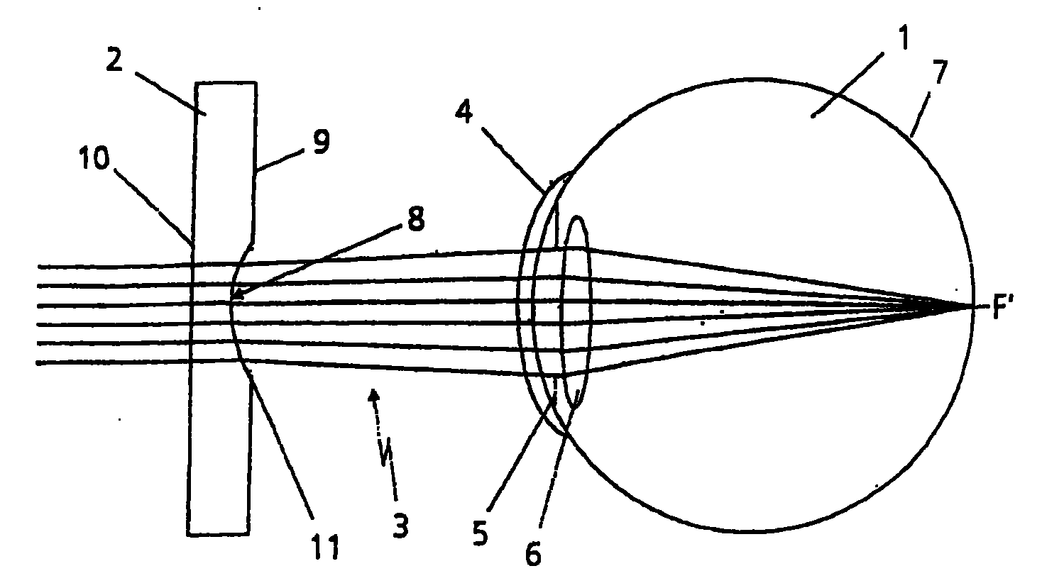
图1是表示在未校正球面像差时一束光线的原理示意图。FIG. 1 is a schematic diagram showing the principle of a beam of light when spherical aberration is not corrected.
图2是表示被投影的原图形的原理示意图。Fig. 2 is a schematic diagram showing the principle of the projected original graphics.
图3a和图3b是表示具有畸变的反射分布的原理示意图。Fig. 3a and Fig. 3b are schematic diagrams showing the principle of reflection distribution with distortion.
图4是表示球面像差被校正时一束光线的原理示意图。FIG. 4 is a schematic diagram showing the principle of a beam of light when the spherical aberration is corrected.
图5描述眼球的未校正球面像差。Figure 5 depicts the uncorrected spherical aberration of the eye.
图6示范性描述球面像差校正。FIG. 6 exemplarily depicts spherical aberration correction.
图7表示弧矢h,弧矢h的定义是镜片的镜顶S与光轴上天底L之间的距离。Figure 7 shows the sagittal h, which is defined as the distance between the mirror top S of the lens and the nadir L on the optical axis.
图1所示的是一个眼球1与透镜2构成的系统。该透镜2最好是一个镜片。当然,该透镜还可以是隐形镜片或眼内镜片(intraocular lens)。该透镜2可用玻璃和/或塑料加工形成。为了校正屈光不正,还可提供诸如隐形镜片和镜片之类相互组合的各不相同的透镜2。光束3从某个物体(未作图示)发出,透过透镜2的光学系统,再通过角膜4、瞳孔5和眼球晶状体6射到眼球1的视网膜7上。在该视网膜7上有眼球1的一个中心凹,通常在该中心凹上受光体的密度为最大。在理想状态,所有光学信息应射到中心凹里。这意味着视网膜7上的中心凹构成一个焦点F’,光束3应相交在该点上。但是,只有在小瞳孔开度时才能出现这种情况。因为对于每只眼球1均会发生球面像差,透过晶状体6的光束3不都在焦点F’即视网膜7的中心凹里汇合。通常入射光束3靠瞳孔5边缘越近,光束与视网膜的交点离理想的交点F’越远。Shown in FIG. 1 is a system composed of an eyeball 1 and a
因为在原理方面本专利涉及任何眼球的校正,也就是说,本专利同样涉及正常视力(折光正常)的眼球,图1描述的透镜2只是作为原理图。Because this patent relates to the correction of any eyeball in terms of principle, that is to say, this patent also relates to eyeballs with normal vision (normal refraction), and the
为了除去球面像差,首先须取得屈光不正眼球1的具体数据。为此目的,采用波前检测方法。该方法采用波前像差仪(aberrometer)例如哈特曼-肖克传感器。In order to remove the spherical aberration, it is first necessary to obtain the specific data of the ametropic eyeball 1 . For this purpose, a wavefront detection method is employed. The method employs a wavefront aberrometer such as a Hartmann-Schoke sensor.
图2所示的是在视网膜7上成像的各光束的图形。在该视网膜7上产生了由眼球1的像差所造成的入射光束3的畸变图像。与该入射光束3同轴安装的一架集成的CCD(电荷耦合器件)照相机,在图像被确定为无像差的一个非常小的立体角下,摄下该畸变图形。一种脱机程序通过理论上/实际上比较入射分光束(incident partialbeam)3相对位置与视网膜7上所产生的各点相对位置计算像差。因此,在数学上,像差用zernike多项式系数描述并作为一种高度分布图来表示。图3a和图3b中所反映的分布图具有原图形的两个不同的畸变。相对于图3b,图3a所示的是畸变较小的分布图。FIG. 2 shows the patterns of the respective light beams imaged on the
图4所示的是一个眼球连同球面像差被校正透镜2的系统。FIG. 4 shows a system of eyeballs together with spherical aberration-corrected
用波前检测方法检测眼球1,将产生有关眼球1的成像性质(特别是有关作为瞳孔开度5函数的像差)的精确结论。为了测定眼球1的成像性质或眼球1的球面、圆柱面和轴线的傍轴值(paraxialvalues),可使用任何能够提供本专利所需波前的设计成的装置。Detection of the eyeball 1 by means of wavefront detection will lead to precise conclusions about the imaging properties of the eyeball 1, in particular about the aberrations as a function of the
当然,傍轴值还能通过折射测量或者借助于测眼膜术进行测定。举例来说,这些值可以由眼镜商或眼科医生测定。测眼膜术被认为是一种客观地测定眼球折射的人工方法。在这样的情况中,在被测对象的眼球视网膜上观察到发光(light phenomena)(二次光源)的移动方向。由此得到有关屈光不正的结论。Of course, the paraxial value can also be determined by refractometry or by means of oculometry. These values can be determined by an optician or an ophthalmologist, for example. Ophthalmology is considered to be an artificial method for objectively measuring the refraction of the eyeball. In such a case, a moving direction of a light phenomenon (secondary light source) is observed on the eye retina of the subject. From this, conclusions about refractive errors are drawn.
同样,为了校正高级像差,用波前检测方法测定瞳孔开度5的大小。因为在日光和微光时瞳孔开度5不同,因而一个人的视敏度也能改变。所以,先在日光中再在微光中使透镜2适合于校正这个人的屈光不正是方便的。如果合适,如有需要也可例如在微光中观看来进一步调整透镜2,作为这种情况下确定的瞳孔开度5和视敏度的函数。Also, in order to correct high-order aberrations, the size of the
本示范性实施例涉及在视点8周围的后表面(即该透镜2的眼球一侧表面9),利用通过为修正透镜2的至少一个表面而作的适当的光学计算所取得的数据,使得在视网膜7的中心凹里实现以上已描述的光束3的理想汇合。在没有透镜2时检测眼球1,产生畸变波前。为了除去球面像差,必须产生一个与已存在的波前相反的波前。将相反波前的数据引入到透镜2视点8的周围的后表面9上,以产生至少一个非球面。The present exemplary embodiment relates to the rear surface around the viewpoint 8 (i.e., the eyeball-side surface 9 of the lens 2), using data obtained by performing appropriate optical calculations for correcting at least one surface of the
这里,非球面被理解为与球面形状不同的旋转对称曲面的一部分。因此,由于非球面的结构,光束3在视网膜7上的中心凹的焦点F’相交。因而,球面像差被消除。同样,曲面能够是复曲面或自由形状曲面,具体取决于视敏度的改进目标。Here, an aspheric surface is understood to be a part of a rotationally symmetrical curved surface that is different in shape from a spherical surface. Thus, due to the structure of the aspheric surface, the focal point F' of the fovea of the light beams 3 on the
一个复曲面表示一个具有二个相互垂直的不同曲率的主截面的曲面的一部分。在该复曲面的情况下,穿过这两个主截面中的至少一个的截面不是圆形。A toric surface represents a portion of a surface having two mutually perpendicular principal sections of different curvature. In the case of this toric surface, the section through at least one of the two main sections is not circular.
自由形状曲面被认为是一个既不旋转对称也不轴向对称的非球面。A freeform surface is considered to be an asphere that is neither rotationally nor axially symmetric.
眼球1的球面像差还可称为孔径像差(aperture aberration),因相同的作用,其校正同样可在透镜2避开眼球1的面10上作出。该校正也可同时在透镜2的二个面9和10上作出。The spherical aberration of the eyeball 1 can also be called aperture aberration (aperture aberration), and its correction can also be made on the
球面像差的校正对于各种形状的透镜,特别是对于各种形状的镜片,基本上是可能的。在单光透镜(single-vision lenses)情况下,还有在具有棱镜作用(prismatic action)的单光透镜情况下,通过插入一个非球面在视点8周围改进透镜2。Correction of spherical aberration is basically possible for lenses of various shapes, especially for lenses of various shapes. In the case of single-vision lenses, but also in the case of single-vision lenses with prismatic action, the
特别是在镜片的情况下,使用屈光作用数(the number ofdioptric actions)来区别双光透镜(双焦透镜)和三光透镜(三焦透镜)。双光透镜的二个部分(即远视区和阅读区)具有不同的折射率,而特别供远视者使用。该远视者需要一个远距离镜片和一个近距离镜片。如果阅读区还进一步分成阅读距离(reading distance)部分和中距离部分,并且例如该中距离部分只有整个阅读区一半的作用,那么就成为三光透镜,即具有三种作用的镜片。Especially in the case of lenses, the number of dioptric actions is used to distinguish bifocal lenses (bifocal lenses) from trifocal lenses (trifocal lenses). The two parts of the bifocal lens (ie the distance vision area and the reading area) have different refractive indices and are especially used by hyperopic people. The farsighted person needs a distance lens and a near distance lens. If the reading area is further divided into a reading distance (reading distance) part and a middle distance part, and for example, the middle distance part only has half the effect of the entire reading area, then it becomes a three-light lens, that is, a lens with three functions.
在双焦透镜的情况下,主镜片与阅读区的材料之间的分隔面可以合适地成形。在这种情况下,非球面被插入远视区一次,再被插入阅读区一次。对于视敏度略微减少的透镜2,可以在边缘急剧地,或在其它地方通过柔软或平滑的过渡,完成最大视敏度区8到正常区的过渡。渐进镜片(progressive lenses)可以用于这样的平滑过渡。In the case of bifocal lenses, the separation plane between the main optic and the material of the reading zone can be suitably shaped. In this case, the aspheric surface is inserted once in the distance vision zone and once in the reading zone. For
渐进镜片被认为是具有一个非旋转对称面的透镜2,而在该透镜2的整个曲面的一部分范围内,聚焦作用是连续变化的。为了在渐进镜片的情况下校正球面像差,远距和近距这二个视点的周围分别作了修正。如果需要的话,可引入渐进区(progression zone)。A progressive lens is considered to be a
图5表明正常观看的眼球(正常眼)1的球面像差是瞳孔直径p的函数。可以看到,球面像差与瞳孔直径p的大小相关。这就是说,球面像差还随着瞳孔5的增大而增大。在本示范性实施例中,瞳孔直径p的大小为6mm。在光束3靠近瞳孔边缘时,眼球1是近视,其屈光度为-0.5焦度。而在瞳孔直径p的大小为2mm时,球面像差约为-0.075焦度。在本示范性实施例中,高级像差或球面像差在瞳孔5的范围内被认为是旋转对称的,因而可以用其横截面(cross section)表示。Fig. 5 shows the spherical aberration of a normally seeing eyeball (normal eye) 1 as a function of the pupil diameter p. It can be seen that the spherical aberration is related to the size of the pupil diameter p. That is to say, the spherical aberration also increases as the
图6表示透镜2(其配屈调整为0焦度而折射率等于1.6)的球面像差的校正弧矢h为瞳孔直径p的函数。弧矢h表示折射镜面的曲面镜顶S和光轴垂线的天底点(nadir point)L之间的距离,用光束在高度H的入射点A表示(见图7)。此示范性实施例图示说明,为了校正图5所述球面像差,须在图4所示的透镜2的眼球一侧的镜面9上采用哪一种校正。容易地看到,这种情况涉及的是一个偏离球面形状的曲面,即一个非球面。FIG. 6 shows the correction sagittal h of the spherical aberration of the lens 2 (whose refraction is adjusted to 0 power and the refractive index is equal to 1.6) as a function of the pupil diameter p. The sagittal h represents the distance between the curved mirror top S of the refracting mirror and the nadir point (nadir point) L of the vertical line of the optical axis, expressed by the incident point A of the beam at height H (see Figure 7). This exemplary embodiment illustrates which correction has to be applied on the eyeball-side mirror surface 9 of the
透镜2在至少一个折射镜面里有折射和/或衍射结构,这种结构起到屈光不正的屈光校正作用并在至少一个观察方向上校正至少一个高级像差。最好只在透镜2(特别是镜片)的一个面9或10配有这样的结构。该面9或10最好只有折射结构。衍射结构可以用于例如隐形镜片和镜片。因此,在隐形镜片的后部可配有显微镜细调步骤中那样的很多同心布置的圆环。这些“凹槽“能用肉眼看到或感觉到,但被泪液充满着。这二种结构一起,除了光折射之外,还能产生光分离(division of light)。因此,所产生的透镜2因焦点深度的变换而具有多视觉作用(multiple-vision action)。从近到远的视觉印象可以具有不同的清晰度同时在视网膜7上成像。The
因此,(不仅)球面像差,而且其它高级像差,能够通过采用非球面而基本上减少或消除。至少50%(最好75%)高级像差能够仅通过校正诸如球面、圆柱面和轴线之类的中心像差而得到补偿。可以想象,高级像差可以通过校正措施,例如:将适当计算的校正曲面(非球面、复曲面或自由形状面)加到透镜2(最好是镜片)的至少一个折射面9和/或10上,就能得到补偿。但是,也可以证实:例如球面等效值(sph+zy1/2)的校正通常对于还要补偿至少50%的球面像差是足够的。Thus, (not only) spherical aberration, but also other higher order aberrations can be substantially reduced or eliminated by employing aspheric surfaces. At least 50% (preferably 75%) of higher order aberrations can be compensated by correcting only central aberrations such as spherical, cylindrical and axial. It is conceivable that advanced aberrations can be corrected by means of, for example, the addition of appropriately calculated corrective surfaces (aspheric, toric or freeform) to at least one of the refractive surfaces 9 and/or 10 of the lens 2 (preferably an optic). above, you will be compensated. However, it has also been found that a correction such as the spherical equivalent (sph+zy1/2) is generally sufficient to also compensate for spherical aberrations of at least 50%.
仅通过校正中心像差就能补偿至少50%(最好85%)的球面像差。因而,制造透镜(特别是镜片)时需要考虑的参数量可减少到中心像差。因此,用结构简单的曲面(如旋转对称的非球面)代替相对复杂的曲面(如自由形状曲面)是可能的,从而简化了制造工艺。At least 50% (preferably 85%) of spherical aberration can be compensated by correcting only central aberration. Thus, the number of parameters that need to be considered in the manufacture of lenses, especially optics, can be reduced to central aberrations. Therefore, it is possible to replace a relatively complex curved surface (such as a free-form curved surface) with a structurally simple curved surface (such as a rotationally symmetrical aspheric surface), thereby simplifying the manufacturing process.
Claims (27)
Applications Claiming Priority (2)
| Application Number | Priority Date | Filing Date | Title |
|---|---|---|---|
| DE10246324.7 | 2002-10-04 | ||
| DE10246324 | 2002-10-04 |
Publications (2)
| Publication Number | Publication Date |
|---|---|
| CN1729419A CN1729419A (en) | 2006-02-01 |
| CN100392473C true CN100392473C (en) | 2008-06-04 |
Family
ID=32086843
Family Applications (1)
| Application Number | Title | Priority Date | Filing Date |
|---|---|---|---|
| CNB2003801045796A Expired - Lifetime CN100392473C (en) | 2002-10-04 | 2003-10-02 | A kind of manufacturing method of lens and manufactured lens |
Country Status (8)
| Country | Link |
|---|---|
| US (1) | US7556381B2 (en) |
| EP (1) | EP1546791A1 (en) |
| JP (2) | JP5096662B2 (en) |
| CN (1) | CN100392473C (en) |
| AU (1) | AU2003276034A1 (en) |
| CA (1) | CA2501217C (en) |
| DE (1) | DE10393231D2 (en) |
| WO (1) | WO2004034129A1 (en) |
Families Citing this family (61)
| Publication number | Priority date | Publication date | Assignee | Title |
|---|---|---|---|---|
| US7434936B2 (en) * | 2002-12-06 | 2008-10-14 | Amo Manufacturing Usa, Llc | Residual accommodation threshold for correction of presbyopia and other presbyopia correction using patient data |
| DE102004003688A1 (en) * | 2004-01-24 | 2005-08-18 | Carl Zeiss | Procedure and eye test device to determine the need for a visual aid in the dark and / or twilight and a set of visual aids |
| DE102004029475A1 (en) * | 2004-06-18 | 2006-01-26 | Henkel Kgaa | New enzymatic bleaching system |
| US20060116763A1 (en) * | 2004-12-01 | 2006-06-01 | Simpson Michael J | Contrast-enhancing aspheric intraocular lens |
| DK1753373T3 (en) | 2005-04-05 | 2008-08-18 | Alcon Inc | Intraocular lens |
| AR062067A1 (en) * | 2006-07-17 | 2008-10-15 | Novartis Ag | TORICAS CONTACT LENSES WITH CONTROLLED OPTICAL POWER PROFILE |
| EP2008575A1 (en) * | 2007-06-27 | 2008-12-31 | Essilor International | Systems and methods for improving the receptiveness of a person to a training session for improving visual perception |
| US8747466B2 (en) | 2007-08-27 | 2014-06-10 | Amo Groningen, B.V. | Intraocular lens having extended depth of focus |
| US8740978B2 (en) | 2007-08-27 | 2014-06-03 | Amo Regional Holdings | Intraocular lens having extended depth of focus |
| US20090062911A1 (en) * | 2007-08-27 | 2009-03-05 | Amo Groningen Bv | Multizonal lens with extended depth of focus |
| US8974526B2 (en) | 2007-08-27 | 2015-03-10 | Amo Groningen B.V. | Multizonal lens with extended depth of focus |
| US9216080B2 (en) | 2007-08-27 | 2015-12-22 | Amo Groningen B.V. | Toric lens with decreased sensitivity to cylinder power and rotation and method of using the same |
| WO2009076500A1 (en) * | 2007-12-11 | 2009-06-18 | Bausch & Lomb Incorporated | Method and apparatus for providing eye optical systems with extended depths of field |
| AU2009214036B2 (en) | 2008-02-15 | 2014-04-17 | Amo Regional Holdings | System, ophthalmic lens, and method for extending depth of focus |
| US8439498B2 (en) | 2008-02-21 | 2013-05-14 | Abbott Medical Optics Inc. | Toric intraocular lens with modified power characteristics |
| US8231219B2 (en) | 2008-04-24 | 2012-07-31 | Amo Groningen B.V. | Diffractive lens exhibiting enhanced optical performance |
| US7871162B2 (en) | 2008-04-24 | 2011-01-18 | Amo Groningen B.V. | Diffractive multifocal lens having radially varying light distribution |
| US8862447B2 (en) | 2010-04-30 | 2014-10-14 | Amo Groningen B.V. | Apparatus, system and method for predictive modeling to design, evaluate and optimize ophthalmic lenses |
| US20100079723A1 (en) * | 2008-10-01 | 2010-04-01 | Kingston Amanda C | Toric Ophthalimc Lenses Having Selected Spherical Aberration Characteristics |
| CA2784794C (en) | 2009-12-18 | 2018-02-20 | Hendrik A. Weeber | Ophthalmic lens, systems and methods with angular varying phase delay |
| US8331048B1 (en) | 2009-12-18 | 2012-12-11 | Bausch & Lomb Incorporated | Methods of designing lenses having selected depths of field |
| US8430511B2 (en) * | 2010-10-07 | 2013-04-30 | Vicoh, Llc | Kit of higher order aberration contact lenses and methods of use |
| US8894208B2 (en) * | 2010-10-07 | 2014-11-25 | Vicoh, Llc | Kit of higher order aberration contact lenses and methods of use |
| US9817246B2 (en) | 2010-12-01 | 2017-11-14 | Amo Groningen B.V. | Multifocal lens having an optical add power progression, and a system and method of providing same |
| US9931200B2 (en) | 2010-12-17 | 2018-04-03 | Amo Groningen B.V. | Ophthalmic devices, systems, and methods for optimizing peripheral vision |
| US8894204B2 (en) | 2010-12-17 | 2014-11-25 | Abbott Medical Optics Inc. | Ophthalmic lens, systems and methods having at least one rotationally asymmetric diffractive structure |
| TWI588560B (en) | 2012-04-05 | 2017-06-21 | 布萊恩荷登視覺協會 | Lens, device, method and system for refractive error |
| AU2013308109B2 (en) | 2012-08-31 | 2018-04-19 | Amo Groningen B.V. | Multi-ring lens, systems and methods for extended depth of focus |
| US9201250B2 (en) | 2012-10-17 | 2015-12-01 | Brien Holden Vision Institute | Lenses, devices, methods and systems for refractive error |
| TWI600418B (en) | 2012-10-17 | 2017-10-01 | 布萊恩荷登視覺協會 | Lens, device, method and system for refractive error |
| CA2877203A1 (en) | 2012-12-04 | 2014-06-12 | Amo Groningen B.V. | Lenses, systems and methods for providing binocular customized treatments to correct presbyopia |
| AU2014228357B2 (en) | 2013-03-11 | 2018-08-23 | Johnson & Johnson Surgical Vision, Inc. | Intraocular lens that matches an image surface to a retinal shape, and method of designing same |
| CA2942198C (en) | 2014-03-10 | 2023-08-01 | Amo Groningen B.V. | Enhanced toric lens that improves overall vision where there is a local loss of retinal function |
| CN106714731B (en) | 2014-04-21 | 2019-09-27 | 阿莫格罗宁根私营有限公司 | Ophthalmic devices, systems and methods for improving peripheral vision |
| BR112017004765B1 (en) | 2014-09-09 | 2022-08-23 | Staar Surgical Company | LENS CONFIGURED FOR IMPLANTATION IN A HUMAN EYE |
| US12127934B2 (en) | 2014-09-09 | 2024-10-29 | Staar Surgical Company | Method of Providing Modified Monovision to a Subject with a First Lens and a Second Lens |
| US10624735B2 (en) | 2016-02-09 | 2020-04-21 | Amo Groningen B.V. | Progressive power intraocular lens, and methods of use and manufacture |
| AU2017229594B2 (en) | 2016-03-09 | 2022-06-16 | Staar Surgical Company | Ophthalmic implants with extended depth of field and enhanced distance visual acuity |
| EP4470500A3 (en) | 2016-03-11 | 2025-02-26 | Amo Groningen B.V. | Intraocular lenses that improve peripheral vision |
| EP3432768B1 (en) | 2016-03-23 | 2020-04-29 | Johnson & Johnson Surgical Vision, Inc. | Power calculator for an ophthalmic apparatus with corrective meridians having extended tolerance or operation band |
| EP3433667B1 (en) | 2016-03-23 | 2022-09-28 | Johnson & Johnson Surgical Vision, Inc. | Ophthalmic apparatus with corrective meridians having extended tolerance band with freeform refractive surfaces |
| WO2017182878A1 (en) | 2016-04-19 | 2017-10-26 | Amo Groningen B.V. | Ophthalmic devices, system and methods that improve peripheral vision |
| WO2018022042A1 (en) * | 2016-07-27 | 2018-02-01 | Carl Zeiss Vision International Gmbh | Method for determining an improved design for a progressive lens taking into account higher order aberrations of the eye |
| WO2018078439A2 (en) | 2016-10-25 | 2018-05-03 | Amo Groningen B.V. | Realistic eye models to design and evaluate intraocular lenses for a large field of view |
| EP3595584A1 (en) | 2017-03-17 | 2020-01-22 | AMO Groningen B.V. | Diffractive intraocular lenses for extended range of vision |
| US10739227B2 (en) | 2017-03-23 | 2020-08-11 | Johnson & Johnson Surgical Vision, Inc. | Methods and systems for measuring image quality |
| US11523897B2 (en) | 2017-06-23 | 2022-12-13 | Amo Groningen B.V. | Intraocular lenses for presbyopia treatment |
| EP3639084B1 (en) | 2017-06-28 | 2025-01-01 | Amo Groningen B.V. | Extended range and related intraocular lenses for presbyopia treatment |
| CA3067116A1 (en) | 2017-06-28 | 2019-01-03 | Amo Groningen B.V. | Diffractive lenses and related intraocular lenses for presbyopia treatment |
| US11327210B2 (en) | 2017-06-30 | 2022-05-10 | Amo Groningen B.V. | Non-repeating echelettes and related intraocular lenses for presbyopia treatment |
| EP3687447A1 (en) | 2017-11-30 | 2020-08-05 | AMO Groningen B.V. | Intraocular lenses that improve post-surgical spectacle independent and methods of manufacturing thereof |
| EP3837571B1 (en) | 2018-08-17 | 2023-08-02 | Staar Surgical Company | Polymeric composition exhibiting nanogradient of refractive index |
| AU2019394013B2 (en) | 2018-12-06 | 2025-08-14 | Amo Groningen B.V. | Diffractive lenses for presbyopia treatment |
| CN110711050B (en) * | 2019-10-24 | 2024-08-23 | 西安眼得乐医疗科技有限公司 | Intraocular lens |
| US11886046B2 (en) | 2019-12-30 | 2024-01-30 | Amo Groningen B.V. | Multi-region refractive lenses for vision treatment |
| CN115380239A (en) | 2019-12-30 | 2022-11-22 | 阿莫格罗宁根私营有限公司 | Lens with irregular width diffraction profile for vision treatment |
| CN115697249A (en) | 2020-06-01 | 2023-02-03 | 应用奈米医材科技股份有限公司 | Bifacial aspheric diffractive multifocal lenses and their manufacture and use |
| JP7505995B2 (en) | 2021-01-27 | 2024-06-25 | ホヤ レンズ タイランド リミテッド | Eyeglass lens design method, manufacturing method, and design system |
| JP7505996B2 (en) | 2021-01-27 | 2024-06-25 | ホヤ レンズ タイランド リミテッド | Eyeglass lens design method, manufacturing method, and design system |
| WO2022233683A1 (en) | 2021-05-05 | 2022-11-10 | Amo Groningen B.V. | Ring halometer system and method for quantifying dysphotopsias |
| CA3234381A1 (en) | 2021-10-04 | 2023-04-13 | Staar Surgical Company | Ophthalmic implants for correcting vision with a tunable optic, and methods of manufacture and use |
Citations (4)
| Publication number | Priority date | Publication date | Assignee | Title |
|---|---|---|---|---|
| US4957506A (en) * | 1988-09-06 | 1990-09-18 | Essilor International Cie Generale D'optique | Optical system using an ophthalmic lens and an intra-ocular lens to improve the sight of a person suffering from macular degeneration |
| EP0472291A1 (en) * | 1990-07-24 | 1992-02-26 | JOHNSON & JOHNSON VISION PRODUCTS, INC. | Method of producing lenses |
| US5777719A (en) * | 1996-12-23 | 1998-07-07 | University Of Rochester | Method and apparatus for improving vision and the resolution of retinal images |
| US6224211B1 (en) * | 1999-06-08 | 2001-05-01 | Medjet, Inc. | Super vision |
Family Cites Families (22)
| Publication number | Priority date | Publication date | Assignee | Title |
|---|---|---|---|---|
| US1356670A (en) | 1919-06-24 | 1920-10-26 | American Optical Corp | Lens |
| DE1805561C3 (en) * | 1967-10-30 | 1980-10-23 | Societe Des Lunetiers, Paris | Ophthalmic lens with strong refractive power and predetermined astigmatism |
| US4925518A (en) | 1988-07-29 | 1990-05-15 | Wasserman Nelson M | Compliant lens blocks and method of using them |
| US5380387A (en) | 1992-10-13 | 1995-01-10 | Loctite Corporation | Lens blocking/deblocking method |
| EP0663179A1 (en) | 1994-01-12 | 1995-07-19 | Ciba-Geigy Ag | Spatial refractometer |
| EP0900403B1 (en) * | 1996-03-21 | 2003-05-28 | Sola International Holdings, Ltd. | Improved single vision lenses |
| CN1196994A (en) | 1997-04-18 | 1998-10-28 | 王延年 | Method and appts. for plane super-precision grinding and polishing optical glass |
| FR2772489B1 (en) * | 1997-12-16 | 2000-03-10 | Essilor Int | MULTIFOCAL OPHTHALMIC LENSES WITH VARIABLE SPHERICAL ABERRATION FOLLOWING ADDITION AND AMETROPIA |
| JP2002511158A (en) * | 1998-06-04 | 2002-04-09 | ソーラ・インターナショナル・ホールディングス・リミテッド | Molded ophthalmic lens |
| US6183084B1 (en) * | 1998-07-30 | 2001-02-06 | Johnson & Johnson Vision Care, Inc. | Progressive addition lenses |
| US6149271A (en) * | 1998-10-23 | 2000-11-21 | Innotech, Inc. | Progressive addition lenses |
| US6305802B1 (en) * | 1999-08-11 | 2001-10-23 | Johnson & Johnson Vision Products, Inc. | System and method of integrating corneal topographic data and ocular wavefront data with primary ametropia measurements to create a soft contact lens design |
| DE10024080A1 (en) | 2000-05-17 | 2001-11-22 | Asclepion Meditec Ag | Method and device for complete correction of sight defects in human eye uses rays from wave front and topography analyzers to scan eye and send signals to controller for processing into ideal optical system for that eye |
| CN100473371C (en) | 1999-08-11 | 2009-04-01 | 阿斯科莱平医疗技术股份公司 | Method and device for completely correcting visual defects of the human eye |
| DE19954523C2 (en) | 1999-11-12 | 2002-01-31 | Johannes Junger | Process for surface treatment of a contact lens for individual adaptation to the eye system |
| US6695449B2 (en) * | 2000-08-17 | 2004-02-24 | Novartis Ag | Lens design to enhance vision quality |
| AU2001296567B2 (en) * | 2000-10-10 | 2006-07-06 | University Of Rochester | Determination of ocular refraction from wavefront aberration data |
| US6554425B1 (en) * | 2000-10-17 | 2003-04-29 | Johnson & Johnson Vision Care, Inc. | Ophthalmic lenses for high order aberration correction and processes for production of the lenses |
| US6547391B2 (en) * | 2000-12-08 | 2003-04-15 | Johnson & Johnson Vision Care, Inc. | Ocular aberration correction taking into account fluctuations due to biophysical rhythms |
| US20020071095A1 (en) * | 2000-12-08 | 2002-06-13 | Roffman Jefrey H. | Composite surface contact lenses |
| IL143503A0 (en) | 2001-05-31 | 2002-04-21 | Visionix Ltd | Aberration correction spectacle lens |
| US6836371B2 (en) * | 2002-07-11 | 2004-12-28 | Ophthonix, Inc. | Optical elements and methods for making thereof |
-
2003
- 2003-10-02 AU AU2003276034A patent/AU2003276034A1/en not_active Abandoned
- 2003-10-02 WO PCT/EP2003/010955 patent/WO2004034129A1/en not_active Ceased
- 2003-10-02 DE DE10393231T patent/DE10393231D2/en not_active Ceased
- 2003-10-02 EP EP03807835A patent/EP1546791A1/en not_active Withdrawn
- 2003-10-02 CA CA2501217A patent/CA2501217C/en not_active Expired - Fee Related
- 2003-10-02 JP JP2004542413A patent/JP5096662B2/en not_active Expired - Lifetime
- 2003-10-02 CN CNB2003801045796A patent/CN100392473C/en not_active Expired - Lifetime
- 2003-10-02 US US10/529,246 patent/US7556381B2/en not_active Expired - Lifetime
-
2010
- 2010-08-27 JP JP2010191538A patent/JP2011008287A/en active Pending
Patent Citations (4)
| Publication number | Priority date | Publication date | Assignee | Title |
|---|---|---|---|---|
| US4957506A (en) * | 1988-09-06 | 1990-09-18 | Essilor International Cie Generale D'optique | Optical system using an ophthalmic lens and an intra-ocular lens to improve the sight of a person suffering from macular degeneration |
| EP0472291A1 (en) * | 1990-07-24 | 1992-02-26 | JOHNSON & JOHNSON VISION PRODUCTS, INC. | Method of producing lenses |
| US5777719A (en) * | 1996-12-23 | 1998-07-07 | University Of Rochester | Method and apparatus for improving vision and the resolution of retinal images |
| US6224211B1 (en) * | 1999-06-08 | 2001-05-01 | Medjet, Inc. | Super vision |
Also Published As
| Publication number | Publication date |
|---|---|
| US20050259222A1 (en) | 2005-11-24 |
| JP2006502428A (en) | 2006-01-19 |
| US7556381B2 (en) | 2009-07-07 |
| CA2501217A1 (en) | 2004-04-22 |
| JP5096662B2 (en) | 2012-12-12 |
| AU2003276034A1 (en) | 2004-05-04 |
| WO2004034129A1 (en) | 2004-04-22 |
| JP2011008287A (en) | 2011-01-13 |
| CN1729419A (en) | 2006-02-01 |
| CA2501217C (en) | 2013-01-08 |
| DE10393231D2 (en) | 2005-09-01 |
| EP1546791A1 (en) | 2005-06-29 |
Similar Documents
| Publication | Publication Date | Title |
|---|---|---|
| CN100392473C (en) | A kind of manufacturing method of lens and manufactured lens | |
| US8967798B2 (en) | Method for evaluating eyeglass lens, method for designing eyeglass lens, and method for manufacturing eyeglass lens | |
| Lombardo et al. | Wave aberration of human eyes and new descriptors of image optical quality and visual performance | |
| EP0472291B1 (en) | Method of producing lenses | |
| US5220359A (en) | Lens design method and resulting aspheric lens | |
| US6786602B2 (en) | Aberration correction spectacle lens | |
| JP5534817B2 (en) | Premium optic ophthalmic lens | |
| JP5997351B2 (en) | Manufacturing method of spectacle lens | |
| US20180221140A1 (en) | Intraocular lens that improves overall vision where there is a local loss of retinal function | |
| JP6845804B2 (en) | How to determine spectacle lenses with unwanted astigmatism | |
| TWI890807B (en) | Optical lens and associated molding elements | |
| JP4902895B2 (en) | System for enlarging retinal images | |
| KR20110132381A (en) | Ophthalmic lens with optical sector | |
| KR100790417B1 (en) | Performance Evaluation Method and Design Method of Optical System | |
| KR20060021331A (en) | Contact lens with molded outer periphery | |
| TWI889842B (en) | Optical lens for vision correction and corresponding molding element | |
| CN106444073B (en) | Ophthalmic lens customized for wearer and preparation method thereof | |
| JP2023552732A (en) | Eyeglass lens design, eyeglass lens kit and method for manufacturing eyeglass lenses | |
| KR20250121313A (en) | Prism microlenses on PAL for correction contribution | |
| Atchison | Spectacle lens design–development and present state | |
| JP2023156300A (en) | Eyeglass lens design, eyeglass lens kit and method for manufacturing eyeglass lenses | |
| Atchison | A Review of Spectacle Lens Design |
Legal Events
| Date | Code | Title | Description |
|---|---|---|---|
| C06 | Publication | ||
| PB01 | Publication | ||
| C10 | Entry into substantive examination | ||
| SE01 | Entry into force of request for substantive examination | ||
| ASS | Succession or assignment of patent right |
Owner name: CARL ZEISS VISUAL CO., LTD. Free format text: FORMER OWNER: ZEISS CARL Effective date: 20070914 |
|
| C41 | Transfer of patent application or patent right or utility model | ||
| TA01 | Transfer of patent application right |
Effective date of registration: 20070914 Address after: German Allen Applicant after: CARL ZEISS VISION, Inc. Address before: Germany Cohen Applicant before: CARL ZEISS AG |
|
| C14 | Grant of patent or utility model | ||
| GR01 | Patent grant | ||
| CP01 | Change in the name or title of a patent holder | ||
| CP01 | Change in the name or title of a patent holder |
Address after: German Allen Patentee after: Carle Zeiss optics Co.,Ltd. Address before: German Allen Patentee before: Carl Zeiss Vision GmbH |
|
| CX01 | Expiry of patent term | ||
| CX01 | Expiry of patent term |
Granted publication date: 20080604 |