CN100377879C - Inkjet Fault Tolerance Method - Google Patents
Inkjet Fault Tolerance Method Download PDFInfo
- Publication number
- CN100377879C CN100377879C CNB2004101036187A CN200410103618A CN100377879C CN 100377879 C CN100377879 C CN 100377879C CN B2004101036187 A CNB2004101036187 A CN B2004101036187A CN 200410103618 A CN200410103618 A CN 200410103618A CN 100377879 C CN100377879 C CN 100377879C
- Authority
- CN
- China
- Prior art keywords
- ink
- printed
- line
- column
- Prior art date
- Legal status (The legal status is an assumption and is not a legal conclusion. Google has not performed a legal analysis and makes no representation as to the accuracy of the status listed.)
- Expired - Fee Related
Links
- 238000000034 method Methods 0.000 title claims abstract description 21
- 238000007639 printing Methods 0.000 claims abstract description 34
- 239000011159 matrix material Substances 0.000 claims description 4
- 230000000007 visual effect Effects 0.000 abstract description 3
- 230000000694 effects Effects 0.000 abstract description 2
- 239000000976 ink Substances 0.000 description 35
- 239000000758 substrate Substances 0.000 description 7
- 238000010586 diagram Methods 0.000 description 5
- 230000002950 deficient Effects 0.000 description 3
- 230000003213 activating effect Effects 0.000 description 2
- 238000003384 imaging method Methods 0.000 description 2
- 238000007641 inkjet printing Methods 0.000 description 2
- 230000007257 malfunction Effects 0.000 description 1
- 230000007246 mechanism Effects 0.000 description 1
- 230000003252 repetitive effect Effects 0.000 description 1
Images


Landscapes
- Ink Jet (AREA)
- Particle Formation And Scattering Control In Inkjet Printers (AREA)
Abstract
一种打印方法,其识别由于设备故障将不能打印图象的一部分的情况,并且,如果可能,将墨点横向或纵向移动到相邻的行或列,以便减轻未能在原始位置打印的视觉效果。
A method of printing that recognizes that a portion of an image will not print due to equipment failure and, if possible, moves ink dots laterally or vertically to an adjacent row or column in order to alleviate the visual failure to print in the original position Effect.
Description
本申请是申请日为2000年6月30日,申请号为00819709.1(PCT/AU00/00752),发明名称为“喷墨容错的装置和方法”的申请的分案申请。This application is a divisional application of the application dated June 30, 2000, the application number is 00819709.1 (PCT/AU00/00752), and the title of the invention is "Inkjet fault-tolerant device and method".
技术领域 technical field
本发明涉及数字打印,尤其涉及使用将墨喷射到打印基体上的设备的打印。但是本发明的使用又不局限于喷墨打印设备,它也可以应用于激光打印机、发光二极管打印机以及数字影印机。This invention relates to digital printing, and more particularly to printing using devices that eject ink onto a printing substrate. But the use of the present invention is not limited to inkjet printing equipment, it can also be applied to laser printers, LED printers and digital photocopiers.
背景技术 Background technique
在喷墨打印设备中,打印头有一排喷嘴,当打印基体相对于打印头运动时,墨被通过喷嘴选择性地喷射到基体上。打印头可以通过横跨基体扫描打印水平带,或者,如果是全页宽打印头可以沿着页长方向纵向打印。如果有一个喷嘴堵塞,则在扫描型打印头的情况下,就会造成多条水平空白线,而页宽打印头就会出现一条空白垂直线。这种空白线是不期望出现的,因为它们降低了打印的效果。In an inkjet printing device, the printhead has an array of nozzles through which ink is selectively ejected onto the substrate as the substrate is moved relative to the printhead. The printhead can print horizontal bands by scanning across the substrate, or, in the case of a full page width, the printhead can print longitudinally along the length of the page. If one nozzle becomes clogged, this results in multiple horizontal blank lines in the case of scanning printheads and a single blank vertical line in the case of pagewide printheads. Such blank lines are undesirable because they reduce the quality of the print.
发明内容 Contents of the invention
本发明提供一种修正图像打印的方法,使用该方法,能够减少或有效消除一个或多个堵塞的喷嘴产生的在正常使用中对观察者的眼睛而言明显的视觉效果。当然,本发明还可应用于其它形式的打印,这里,无论是被动还是主动,重复地使用一设备在一基体上产生墨点等。本发明还可应用于激光打印机、发光二极管打印机以及影印机,其中,成像鼓或光源的故障可能在产生的图像中造成重复性的错误。本文提到的图像一词是广义的,泛指任何打印内容,如:文本和线条画。The present invention provides a method of correcting image printing by which the visual effects of one or more clogged nozzles that are noticeable to a viewer's eye in normal use can be reduced or effectively eliminated. Of course, the invention is also applicable to other forms of printing where, whether passive or active, a device is repeatedly used to produce dots of ink on a substrate, etc. The invention is also applicable to laser printers, LED printers, and photocopiers, where failure of the imaging drum or light source may cause repetitive errors in the images produced. The term image is used in this article in a broad sense to refer to any printed content such as text and line drawings.
根据本发明的一个方面,提供一种修改待被一数字打印装置打印的图像的方法,所述装置使用多个可启动的部件将所述图像打印到一表面上,以便补偿所述可启动部件中的至少一个故障部件的故障,以正确地在一个或多个特定的位置打印墨,所述方法包括以下步骤:According to one aspect of the present invention there is provided a method of modifying an image to be printed by a digital printing device which prints the image onto a surface using a plurality of actuatable components to compensate for the actuatable components A failure of at least one of the malfunctioning components to correctly print ink at one or more specific locations, the method comprising the steps of:
a)识别所述故障部件中的至少一个故障部件,以确定所述一个或多个特定位置;a) identifying at least one of said faulty components to determine said one or more specific locations;
b)将计划打印位置从所述特定位置中的至少一个特定位置移动到移位的打印位置,其排列成行,但不是原始图像的打印点矩阵的一部分;b) moving the planned printing position from at least one of said specific positions to a shifted printing position which is arranged in a row but which is not part of the printed dot matrix of the original image;
其中所述特定位置指的是所述故障部件中的至少一个故障部件的计划打印位置。Wherein the specific location refers to a planned printing location of at least one of the faulty components.
从另一个广义方面来讲,本发明提供一种修正待由数字打印设备打印图像的方法,所述设备使用多个类似部件打印图像,以补偿设备的故障,以在一个或多个特定位置正确打印墨,该方法包括如下步骤:识别所述一个或多个特定位置,且对于计划要由所述多个部件的一第一个打印的至少一个特定位置,将计划用于图像中该特定位置的点的打印位置移动到还没有被图像中的其他点使用的移位位置,由此,所述多个部件的一第二个打印计划用于该移位位置的至少部分墨。In another broad aspect, the present invention provides a method of correcting an image to be printed by a digital printing device that prints an image using a plurality of similar components to compensate for a failure of the device to correctly printing ink, the method comprising the steps of: identifying said one or more specific locations, and for at least one specific location planned to be printed by a first of said plurality of parts, applying the plan to the specific location in the image The printing position of the dot is moved to a shifted position not already used by other dots in the image, whereby a second printing of the plurality of components is scheduled for at least some of the inks at the shifted position.
从其他广义的方面来讲,本发明提供了一种打印机,该打印机有一排能够将点行喷射到基体上的设备,和使所述基体相对于这排设备沿基本垂直于所述点行的方向移动的装置,该打印机包括:In other broad aspects, the present invention provides a printer having an array of devices capable of ejecting rows of dots onto a substrate, and with respect to the row of devices, said substrate is positioned in a direction substantially perpendicular to said rows of dots. direction mobile device, the printer includes:
a)确定上述设备中的一个或多个是否不能正常工作的装置;a) means for determining whether one or more of the above-mentioned devices are not functioning properly;
b)控制装置,其分析待打印的图像,确定该通过激活故障设备打印墨滴的时间,并移动打印图像中该点的位置,使该点能够通过激活故障设备任一侧的一个打印设备打印出来。b) control means which analyzes the image to be printed, determines when the ink drop should be printed by activating the failed device, and moves the position of the dot in the printed image so that the dot can be printed by activating one of the printing devices on either side of the failed device come out.
原计划由故障打印设备打印的墨点可以横向、纵向或既横向又纵向地移动。优选能够将墨移动到距离原始位置最近的位置。Ink dots intended to be printed by a malfunctioning printing device may move laterally, vertically, or both. It is preferable to be able to move the ink to a position closest to the original position.
故障打印设备会在打印图像中产生一条或多条有缺陷的线条,所以优选将墨点交替地移动到缺陷线条的两侧。优选只相对于该线横向地移动墨,但是如果同一行里没有可用的打印位置,也可以沿着线条既纵向又横向和纵向地移动墨。墨可以移动到原行位置的上行或下行。A malfunctioning printing device may produce one or more defective lines in the printed image, so it is preferable to alternately move the ink dots to both sides of the defective line. Ink is preferably only moved laterally relative to the line, but ink may also be moved both longitudinally and transversely and longitudinally along the line if no printing position is available in the same line. Ink can be moved up or down from the original row position.
附图说明 Description of drawings
为了更好地了解本发明,请参阅附图以及对优选实施例的叙述,其中,For a better understanding of the present invention, please refer to the accompanying drawings and the description of the preferred embodiments, wherein,
图1是喷墨打印头的一组喷嘴的示意图。Figure 1 is a schematic diagram of a set of nozzles of an inkjet printhead.
图2是图1打印头形成的不具纠错操作的墨点阵列示意图。FIG. 2 is a schematic diagram of an array of ink dots formed by the print head in FIG. 1 without error correction operations.
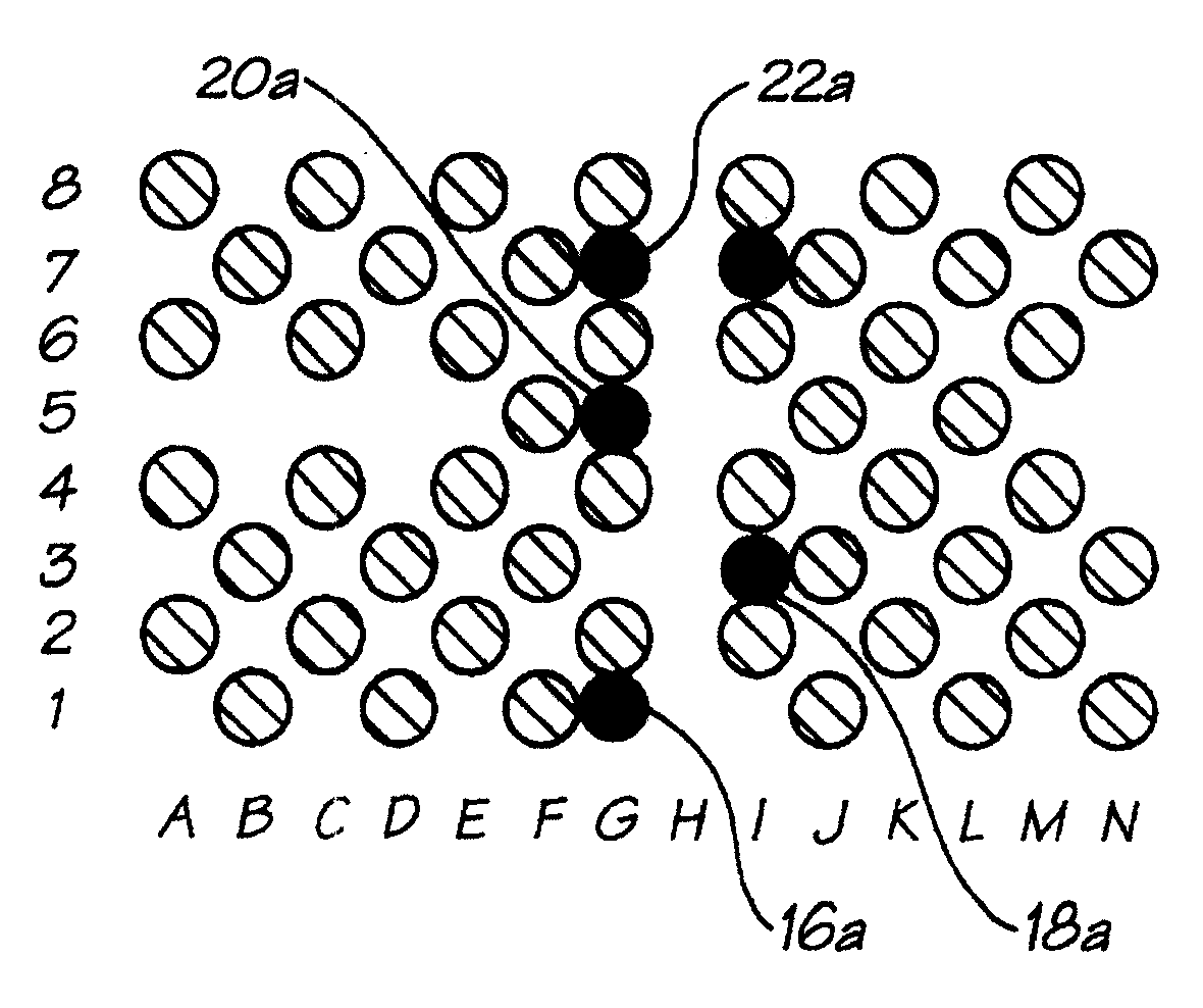
图3是由图1打印头形成的与图2所示相同的墨点阵列示意图,但具有纠错操作。Figure 3 is a schematic diagram of the same ink dot array as that shown in Figure 2 formed by the printhead of Figure 1, but with error correction operations.
图4是另一个由图1打印头形成的不具纠错操作的点阵示意图。FIG. 4 is a schematic diagram of another dot matrix formed by the printhead of FIG. 1 without error correction.
图5是由图1打印头形成的如图4所示相同的点阵示意图,但具有纠错操作。Figure 5 is a schematic diagram of the same dot matrix as shown in Figure 4 formed by the printhead of Figure 1, but with error correction operations.
具体实施方式 Detailed ways
如图1所示,打印头10具有排成一行的一组喷嘴12阵列。为了便于说明,图中仅显示14个喷嘴,事实上一行喷嘴可以包括数十个、数千个喷嘴。纸张沿着基本垂直于喷嘴线的方向从打印头的下面通过,如箭头14所示。打印头可以是固定的,也可以是可移动的。当纸张从打印头下面经过时,喷嘴A至N按照需要选择性地将一个墨水点阵打印到纸张上。该阵列是由一系列的行和列组成,它们之间的距离分别由喷嘴之间的距离和最小进纸步长决定。虽然优选这些点的水平和垂直间隔相等,但是由于控制距离的机制不同,所以这一点不一定能够实现。打印头可以使用页宽打印头或较小打印头,其沿纸张扫描以打下一系列横向打印带。As shown in FIG. 1, a
为了便于说明,假设喷嘴a-g和i-n能够正常工作,而喷嘴h由于某种原因不能正常工作或完全不工作。同时,假设打印机的诊断系统(本领域的技术人员应该知道)已经探测到喷嘴h不能正常工作。通常,喷嘴不工作主要是因为喷嘴被部分或全部堵塞,从而导致打印点墨量不足甚至无墨。For the sake of illustration, assume that nozzles a-g and i-n are functioning properly, while nozzle h is not functioning properly or not at all for some reason. Meanwhile, it is assumed that the diagnostic system of the printer (should be known to those skilled in the art) has detected that the nozzle h is not working properly. Usually, the nozzle does not work mainly because the nozzle is partially or completely blocked, resulting in insufficient ink or even no ink in the printed dot.
图2是由打印头10打印的不带纠错的一部分打印作业的示意图,其中有一个空白列,用“h”标记,对应喷嘴h,而列a-g和i-n已被正确地选择进行打印。根据打印头10是页宽打印头或扫描式打印头,这将导致在打印作业中出现一条或多条空白线。标号为16、18、20和22的未涂阴影的圆代表本应该打印到列h,而没有打印上的墨滴。图3是由打印头10打印的同一图像,但是它经过本发明一实施例的纠错处理。Figure 2 is a schematic illustration of a portion of a print job printed by
如上所述,纸张沿着箭头14的方向经过打印头,以便行1被首先打印。行1中,列h处应该打印点16。由于喷嘴h不能正常工作,所以控制系统判断相邻的喷嘴g和i是否需要打印墨点。因为这两个喷嘴都不需要打印墨点,所以控制系统从列g和列i中选择一个以将一点置于该相应列而不是列h。As mentioned above, the paper passes the print head in the direction of
控制系统通常在缺陷喷嘴的两侧交替打印额外的墨滴,所以优选的打印位置应该是上次打印的墨点的相对侧。当然也存在没有之前数据的情况,例如:就在探测到该喷嘴出现故障之后,或打印机被重新启动时。在这种情况下,控制系统将选择在左列或右列打印。The control system usually prints additional ink drops alternately on both sides of the defective nozzle, so the preferred printing position should be the opposite side of the last printed ink dot. Of course there are situations where there is no previous data, for example just after a malfunction of the nozzle was detected, or when the printer was restarted. In this case, the control system will choose to print in the left or right column.
因为列g和列i都是“空余的”,所以控制系统根据上述原则,选择在位置g打印单个墨点。Because column g and column i are both "empty", the control system chooses to print a single ink dot at position g according to the above principles.
行2中在列h上没有点,所以不需要增加额外的点。There are no dots on column h in
行3中需要在列h上有一点18,而且列g和列h都是空余的,因为上次(在行1)打印的额外点是打印在列g中,因此,这次额外墨点打印在列i。
行4中在列h上也有一个打印点20,但是,这次,列g和列h都要求有点。所以在行4中没有额外墨点。而行5中,列h不要求打印点,且列g和列i都是空余的。由于上一个额外墨点打印在列i,所以选择行5、列g打印原计划在行4,列h中打印的点。There is also a
行6中要求在列h上也有一个打印点22,但这次,列g和列h又都已经被占用了。所以,需要到下一行,行7来打印额外墨点。行7中,列h或列g没有计划打印点,但是,列i中有一个计划打印点。可以回想,点20a是打印在列g,所以这次额外墨点22a的优选位置应该是列i。但是,这个位置不再空闲,所以只能将这一点打印在列g,尽管这会造成下一个额外墨点仍然需要打印到列g中。虽然这在微观上会显得不平衡,但是宏观上讲还是均衡的。Line 6 requires a
图4和图5所示为两组打印作业,平均而言,其比图2、图3需要的点多。这里,仍然假设喷嘴h不能正常工作。首先打印行1,列h中需要打印点30。由于只有列g空闲,所以点30a打印在列g。行2、行3的列h都需要打印一个点,但是由于列g不可用,所以点32a和点34a都打印在列i中,而不管对交替打印的“需要”。Figures 4 and 5 show two sets of print jobs that, on average, require more dots than Figures 2 and 3. Here, it is still assumed that the nozzle h does not work normally.
行4、行6不需要点,但是行5、行7需要点。由于只有一行可用,所以点36a和点38a分别打印到行g和行i中。Lines 4 and 6 do not need dots, but
此外,本发明还可以在与未打印的位置相邻或相近的非移动位置打印大尺寸墨点,并/或在与未打印的位置相邻或相近的行之间打印额外墨点。这通常通过操作打印机的控制装置来启动相邻有故障的喷嘴的打印喷嘴,实现为或者打印较大点或者以较高频率打印点的相应的打印体制。In addition, the present invention may also print large ink dots in non-shifted locations adjacent or near unprinted locations, and/or print additional ink dots between rows adjacent or near unprinted locations. This is usually achieved by operating the printer's controls to activate the printing nozzles adjacent to the faulty nozzle, as a corresponding printing regime that either prints larger dots or prints dots at a higher frequency.
尽管这里介绍的技术在确定何处放置墨点时仅考虑在原行后打印的行,可以理解,可使用前看特征来将点置于原始行之前的行。例如:如果按照后看准则,应该将点置于故障喷嘴的右侧;但是如果前看,就会发现这一列中接下来的几行都需要打印墨点,那么,更好的解决办法就是将墨点打印在原行的左列。同样,该实施例也可以将点平移到下一行。利用前看特征,可以根据打印效果的需要将要求打印的点打印到通常要求位置之前的行。Although the technique described here only considers lines printed after the original line when determining where to place ink dots, it will be appreciated that the look-ahead feature can be used to place dots on lines preceding the original line. For example: If you follow the backward-looking guideline, you should place the dot to the right of the faulty nozzle; but if you look forward, you will find that the next few lines in this column need to print ink dots, then a better solution is to place the Ink dots are printed in the left column of the original row. Likewise, this embodiment can also translate the point to the next row. With the look-ahead feature, the dot required to be printed can be printed to the line before the usual required position according to the needs of the printing effect.
此外,本发明也可以配合激光打印机、LED打印机、影印机以及其它利用独立的部件打印不同的墨点的数字打印机共同使用。例如,在LED打印机中,某个LED可能出现问题;在激光打印机中,某个光敏成像鼓可能出现问题。在这两种情况下,移动点都可以隐藏或减轻设备故障产生的缺陷,改善图像的视觉效果。In addition, the present invention can also be used together with laser printers, LED printers, photocopiers and other digital printers that use independent components to print different ink dots. For example, in an LED printer, an LED may have a problem; in a laser printer, a photosensitive imaging drum may have a problem. In both cases, moving the dots can hide or mitigate imperfections created by equipment failure, improving the visual quality of the image.
Claims (10)
Applications Claiming Priority (1)
| Application Number | Priority Date | Filing Date | Title |
|---|---|---|---|
| PCT/AU2000/000752 WO2002002331A1 (en) | 2000-06-30 | 2000-06-30 | Ink jet fault tolerance using adjacent nozzles |
Related Parent Applications (1)
| Application Number | Title | Priority Date | Filing Date |
|---|---|---|---|
| CN00819709.1A Division CN1191934C (en) | 2000-06-30 | 2000-06-30 | Device and method for inkjet fault tolerance |
Publications (2)
| Publication Number | Publication Date |
|---|---|
| CN1631671A CN1631671A (en) | 2005-06-29 |
| CN100377879C true CN100377879C (en) | 2008-04-02 |
Family
ID=29783656
Family Applications (2)
| Application Number | Title | Priority Date | Filing Date |
|---|---|---|---|
| CNB2004101036187A Expired - Fee Related CN100377879C (en) | 2000-06-30 | 2000-06-30 | Inkjet Fault Tolerance Method |
| CN00819709.1A Expired - Lifetime CN1191934C (en) | 2000-06-30 | 2000-06-30 | Device and method for inkjet fault tolerance |
Family Applications After (1)
| Application Number | Title | Priority Date | Filing Date |
|---|---|---|---|
| CN00819709.1A Expired - Lifetime CN1191934C (en) | 2000-06-30 | 2000-06-30 | Device and method for inkjet fault tolerance |
Country Status (6)
| Country | Link |
|---|---|
| JP (1) | JP2004501009A (en) |
| CN (2) | CN100377879C (en) |
| AT (1) | ATE440727T1 (en) |
| AU (1) | AU2000253742B2 (en) |
| DE (1) | DE60042844D1 (en) |
| ZA (1) | ZA200210190B (en) |
Families Citing this family (22)
| Publication number | Priority date | Publication date | Assignee | Title |
|---|---|---|---|---|
| CN100344452C (en) * | 2000-06-30 | 2007-10-24 | 西尔弗布鲁克研究有限公司 | Image compensation method for ink-ejecting print |
| US7075677B1 (en) | 2000-06-30 | 2006-07-11 | Silverbrook Research Pty Ltd | Ink jet fault tolerance using oversize drops |
| KR100833232B1 (en) * | 2005-09-28 | 2008-05-28 | 삼성전자주식회사 | Defective nozzle compensation method of inkjet image forming apparatus and inkjet image forming apparatus |
| CN101391531B (en) * | 2008-10-31 | 2011-01-26 | 福建实达电脑设备有限公司 | Control method for defect recovery of lattice type typing equipment |
| US9443171B2 (en) * | 2012-07-31 | 2016-09-13 | Hewlett-Packard Development Company, L.P. | Methods for printing with a printhead |
| WO2014161569A1 (en) * | 2013-04-02 | 2014-10-09 | Hewlett-Packard Development Company L.P. | Page wide array printer |
| CN104441997B (en) * | 2014-12-12 | 2016-08-17 | 深圳市润天智数字设备股份有限公司 | Ink-jet printer and print image forming method thereof |
| JP6623787B2 (en) * | 2016-01-25 | 2019-12-25 | セイコーエプソン株式会社 | Printing apparatus and printing method |
| US9573382B1 (en) * | 2016-03-02 | 2017-02-21 | Xerox Corporation | System and method for missing inkjet compensation in a multi-level inkjet printer |
| JP6888244B2 (en) * | 2016-03-28 | 2021-06-16 | セイコーエプソン株式会社 | Droplet ejection control device, droplet ejection control method, and droplet ejection device |
| JP6926456B2 (en) * | 2016-11-30 | 2021-08-25 | セイコーエプソン株式会社 | Print control device, print control method and print control program |
| JPWO2018168191A1 (en) * | 2017-03-16 | 2020-01-16 | コニカミノルタ株式会社 | Image detection device and ink jet recording device |
| US10384444B2 (en) | 2017-04-28 | 2019-08-20 | Canon Kabushiki Kaisha | Recording apparatus and recording method |
| CN108556483B (en) * | 2018-01-17 | 2019-08-09 | 森大(深圳)技术有限公司 | Modify method, apparatus, equipment and the medium of pre-press data compensation abnormal nozzle |
| WO2019141181A1 (en) * | 2018-01-17 | 2019-07-25 | 森大(深圳)技术有限公司 | Ink-jet printer nozzle abnormality compensation method and device, and ink-jet printer |
| WO2019141180A1 (en) | 2018-01-17 | 2019-07-25 | 森大(深圳)技术有限公司 | Nozzle abnormality compensation method, device, and printer |
| JP7119404B2 (en) * | 2018-02-13 | 2022-08-17 | コニカミノルタ株式会社 | Image data processing method, image data processing device and inkjet recording device |
| CN110154557B (en) * | 2019-04-29 | 2021-07-06 | 湖南鼎一致远科技发展有限公司 | Printing control method of thermal transfer printer and thermal transfer printer |
| CN113320292B (en) * | 2020-02-28 | 2022-08-23 | 深圳市汉森软件有限公司 | Processing method, device and equipment for eliminating nozzle splicing channel and storage medium |
| CN114385094B (en) * | 2020-10-16 | 2023-07-14 | 深圳市汉森软件有限公司 | Onepass printing abnormal nozzle compensation method, device, equipment and medium |
| CN112477437B (en) * | 2020-11-13 | 2021-09-21 | 深圳汉弘软件技术有限公司 | Color difference processing method and device, ink-jet printer and storage medium |
| CN113580769B (en) * | 2021-07-08 | 2022-08-02 | 浙江海印数码科技有限公司 | An inkjet printing device and method for compensating for faulty nozzles |
Citations (2)
| Publication number | Priority date | Publication date | Assignee | Title |
|---|---|---|---|---|
| EP0783973A2 (en) * | 1995-12-28 | 1997-07-16 | Canon Kabushiki Kaisha | Method and apparatus for printing |
| EP0863004A2 (en) * | 1997-03-04 | 1998-09-09 | Hewlett-Packard Company | Dynamic multi-pass print mode corrections to compensate for malfunctioning inkjet nozzles |
Family Cites Families (8)
| Publication number | Priority date | Publication date | Assignee | Title |
|---|---|---|---|---|
| JPH0310843A (en) * | 1989-06-08 | 1991-01-18 | Canon Inc | Ink jet recorder |
| JP3353515B2 (en) * | 1994-12-15 | 2002-12-03 | 富士ゼロックス株式会社 | Image output device |
| JPH106488A (en) * | 1996-06-24 | 1998-01-13 | Canon Inc | Ink jet recording method and apparatus |
| US6003980A (en) * | 1997-03-28 | 1999-12-21 | Jemtex Ink Jet Printing Ltd. | Continuous ink jet printing apparatus and method including self-testing for printing errors |
| EP0999935B1 (en) * | 1997-08-01 | 2003-11-05 | Encad, Inc. | Ink jet printer, method and system compensating for nonfunctional print elements |
| US6270187B1 (en) * | 1998-12-14 | 2001-08-07 | Hewlett-Packard Company | Method and apparatus for hiding errors in single-pass incremental printing |
| NL1012376C2 (en) * | 1999-06-17 | 2000-12-19 | Ocu Technologies B V | Method for printing a substrate and a printing device suitable for applying this method. |
| JP4681751B2 (en) * | 2000-05-01 | 2011-05-11 | キヤノン株式会社 | Recording apparatus and recording method |
-
2000
- 2000-06-30 AT AT00938325T patent/ATE440727T1/en not_active IP Right Cessation
- 2000-06-30 JP JP2002506939A patent/JP2004501009A/en active Pending
- 2000-06-30 AU AU2000253742A patent/AU2000253742B2/en not_active Expired
- 2000-06-30 CN CNB2004101036187A patent/CN100377879C/en not_active Expired - Fee Related
- 2000-06-30 DE DE60042844T patent/DE60042844D1/en not_active Expired - Lifetime
- 2000-06-30 CN CN00819709.1A patent/CN1191934C/en not_active Expired - Lifetime
-
2002
- 2002-12-17 ZA ZA200210190A patent/ZA200210190B/en unknown
Patent Citations (2)
| Publication number | Priority date | Publication date | Assignee | Title |
|---|---|---|---|---|
| EP0783973A2 (en) * | 1995-12-28 | 1997-07-16 | Canon Kabushiki Kaisha | Method and apparatus for printing |
| EP0863004A2 (en) * | 1997-03-04 | 1998-09-09 | Hewlett-Packard Company | Dynamic multi-pass print mode corrections to compensate for malfunctioning inkjet nozzles |
Also Published As
| Publication number | Publication date |
|---|---|
| CN1631671A (en) | 2005-06-29 |
| AU2000253742B2 (en) | 2004-05-06 |
| CN1454150A (en) | 2003-11-05 |
| DE60042844D1 (en) | 2009-10-08 |
| CN1191934C (en) | 2005-03-09 |
| ATE440727T1 (en) | 2009-09-15 |
| JP2004501009A (en) | 2004-01-15 |
| ZA200210190B (en) | 2003-08-27 |
| AU2000253742A1 (en) | 2002-04-11 |
Similar Documents
| Publication | Publication Date | Title |
|---|---|---|
| CN100377879C (en) | Inkjet Fault Tolerance Method | |
| EP1303410B1 (en) | Ink jet fault tolerance using adjacent nozzles | |
| JP4931204B2 (en) | Data generating apparatus and data generating method | |
| JP4298486B2 (en) | Recording apparatus, recording method thereof, and program | |
| JP5088200B2 (en) | Printing apparatus and printing apparatus control method | |
| JP4513802B2 (en) | Printing device | |
| JP2010208120A (en) | Liquid jetting apparatus | |
| CN1182964C (en) | Ink jet error correction using large size drops | |
| JP5776348B2 (en) | Image forming apparatus and image forming method | |
| JP4979485B2 (en) | Inkjet recording device | |
| CN1593922A (en) | Image compensation method for ink-ejecting print | |
| JP2014008660A (en) | Inkjet recorder, and method for generating mask pattern | |
| CN1216742C (en) | Ink jet fault tolerance using extra ink dots | |
| JP7268370B2 (en) | Recording device and recording method | |
| JP6054850B2 (en) | Recording apparatus and recording method | |
| JP7210187B2 (en) | LIQUID EJECTING APPARATUS AND LIQUID EJECTING METHOD | |
| JP5079422B2 (en) | Inkjet printing apparatus and printing method | |
| KR100706709B1 (en) | Correcting Ink Jet Defects Using Oversized Ink Drops | |
| KR100799389B1 (en) | Fault Tolerance for Inkjets Using Adjacent Nozzles | |
| JP2008155378A (en) | Printing method and printing apparatus | |
| JP2010208121A (en) | Liquid jetting head and liquid jetting apparatus | |
| US7036897B2 (en) | Method and apparatus for operating a printer | |
| JP2010082971A (en) | Liquid delivery device and delivery control method therefor | |
| JP2006110890A (en) | Ink jet recording apparatus and control method of ink jet recording apparatus | |
| JP4290057B2 (en) | Inkjet recording apparatus, control method therefor, and program |
Legal Events
| Date | Code | Title | Description |
|---|---|---|---|
| C06 | Publication | ||
| PB01 | Publication | ||
| C10 | Entry into substantive examination | ||
| SE01 | Entry into force of request for substantive examination | ||
| C14 | Grant of patent or utility model | ||
| GR01 | Patent grant | ||
| ASS | Succession or assignment of patent right |
Owner name: ZAMTEC LTD. Free format text: FORMER OWNER: SILVERBROOK RESEARCH PTY. LTD. Effective date: 20140326 |
|
| C41 | Transfer of patent application or patent right or utility model | ||
| TR01 | Transfer of patent right |
Effective date of registration: 20140326 Address after: Dublin, Ireland Patentee after: Silverbrook Research Pty Ltd. Address before: New South Wales Australia Patentee before: Silverbrook Research Pty. Ltd. |
|
| C56 | Change in the name or address of the patentee |
Owner name: MAGTE TECHNOLOGY CO., LTD. Free format text: FORMER NAME: ZAMTEC LTD. |
|
| CP01 | Change in the name or title of a patent holder |
Address after: Dublin, Ireland Patentee after: MEMJET TECHNOLOGY LTD. Address before: Dublin, Ireland Patentee before: Silverbrook Research Pty Ltd. |
|
| CF01 | Termination of patent right due to non-payment of annual fee |
Granted publication date: 20080402 Termination date: 20170630 |
|
| CF01 | Termination of patent right due to non-payment of annual fee |