CN100356082C - Inverse type magnetic flow damper - Google Patents
Inverse type magnetic flow damper Download PDFInfo
- Publication number
- CN100356082C CN100356082C CNB2004100688535A CN200410068853A CN100356082C CN 100356082 C CN100356082 C CN 100356082C CN B2004100688535 A CNB2004100688535 A CN B2004100688535A CN 200410068853 A CN200410068853 A CN 200410068853A CN 100356082 C CN100356082 C CN 100356082C
- Authority
- CN
- China
- Prior art keywords
- magnetic
- cylinder
- air gap
- coil
- damper
- Prior art date
- Legal status (The legal status is an assumption and is not a legal conclusion. Google has not performed a legal analysis and makes no representation as to the accuracy of the status listed.)
- Expired - Fee Related
Links
Images


Classifications
-
- F—MECHANICAL ENGINEERING; LIGHTING; HEATING; WEAPONS; BLASTING
- F16—ENGINEERING ELEMENTS AND UNITS; GENERAL MEASURES FOR PRODUCING AND MAINTAINING EFFECTIVE FUNCTIONING OF MACHINES OR INSTALLATIONS; THERMAL INSULATION IN GENERAL
- F16F—SPRINGS; SHOCK-ABSORBERS; MEANS FOR DAMPING VIBRATION
- F16F9/00—Springs, vibration-dampers, shock-absorbers, or similarly-constructed movement-dampers using a fluid or the equivalent as damping medium
- F16F9/32—Details
- F16F9/53—Means for adjusting damping characteristics by varying fluid viscosity, e.g. electromagnetically
- F16F9/535—Magnetorheological [MR] fluid dampers
Landscapes
- Engineering & Computer Science (AREA)
- General Engineering & Computer Science (AREA)
- Physics & Mathematics (AREA)
- Electromagnetism (AREA)
- Mechanical Engineering (AREA)
- Fluid-Damping Devices (AREA)
- Vibration Prevention Devices (AREA)
Abstract
一种逆变型磁流变阻尼器,可应用于建筑结构减振控制及机车减振,它包括有缸体、活塞,与其连接的活塞杆,缸体两端的密封导向装置及缸盖,缸体内腔充有磁流变液并设置有可产生磁场的导磁体和励磁线圈及工作气隙组成的电磁磁路部件,其中缸体由主缸,或主缸和副缸,或主缸和旁通缸组成,特征在于:在磁路部分同时设置励磁线圈和永磁体,由励磁磁场与永磁磁场组成复合磁路,并且电磁磁路中还设置有辅助气隙,以保证在电源切断时,永磁体产生的永磁磁场大部分由工作气隙通过,而使得阻尼器能够工作在大阻尼状态。电磁磁路部件可根据不同的缸体设置在相应的位置。此类阻尼器可与受控结构连接,实现半主动减振控制。本发明具有节省能源、提高控制效率、能够改善磁流变液稳定性等特点。
An inverter-type magneto-rheological damper, which can be applied to the vibration reduction control of building structures and locomotives. It includes a cylinder body, a piston, a piston rod connected to it, sealing and guiding devices at both ends of the cylinder body, and a cylinder head. The inner cavity is filled with magnetorheological fluid and is equipped with an electromagnetic magnetic circuit component composed of a magnet that can generate a magnetic field, an excitation coil and a working air gap. The cylinder body is composed of a master cylinder, or a master cylinder and an auxiliary cylinder, or a master cylinder and The composition of the bypass cylinder is characterized in that: an excitation coil and a permanent magnet are set in the magnetic circuit part at the same time, and the composite magnetic circuit is composed of the excitation magnetic field and the permanent magnetic field, and an auxiliary air gap is also set in the electromagnetic magnetic circuit to ensure that when the power is cut off , most of the permanent magnetic field generated by the permanent magnet passes through the working air gap, so that the damper can work in a large damping state. Electromagnetic magnetic circuit components can be arranged in corresponding positions according to different cylinder bodies. These dampers can be interfaced with controlled structures for semi-active vibration damping control. The invention has the characteristics of saving energy, improving control efficiency, improving the stability of magnetorheological fluid, and the like.
Description
技术领域technical field
本发明涉及一种新型磁流变阻尼器,所提出的逆变型磁流变阻尼器可应用于建筑结构减振控制及机车减振。亦可用于制作用于航天、电子、化工、能源、仪表、医疗、卫生等领域的阻尼器、制动器、离合器、液压阀等。The invention relates to a novel magnetorheological damper, and the proposed inverter magnetorheological damper can be applied to vibration reduction control of building structures and vibration reduction of locomotives. It can also be used to make dampers, brakes, clutches, hydraulic valves, etc. used in aerospace, electronics, chemical industry, energy, instrumentation, medical, health and other fields.
背景技术Background technique
磁流变阻尼器是一类利用磁流变液作为工作介质的半主动控制装置。磁流变液是由细小的软磁性颗粒分散于载液中形成的随外加磁场变化而具有可控流变特性的悬浮液体;当磁流变液受到磁场作用时,其粘度系数将会随之增加,当其受到强磁场作用时就会变成类似“固体”的状态,流动性消失,一旦去掉磁场后,又变成可以流动的液体。磁流变阻尼器利用磁流变液的流变特性,在阻尼器上设置存在磁场的阻尼通道,当阻尼器活塞与缸体发生相对运动时,则会挤压缸中的磁流变液,使其从阻尼通道流过,当阻尼通道没有磁场作用时磁流变液表现为粘性流体,若对阻尼通道内施加磁场时,阻尼通道内的磁流变液发生硬化而成为粘塑性体,导致活塞运动的阻尼力增大。调节磁场强度可以改变磁流变液的屈服强度,从而可以调节阻尼器的阻尼力的大小。The magnetorheological damper is a kind of semi-active control device that uses magnetorheological fluid as the working medium. Magneto-rheological fluid is a suspension liquid with controllable rheological properties that is formed by dispersing fine soft magnetic particles in the carrier liquid as the external magnetic field changes; when the magnetorheological fluid is subjected to a magnetic field, its viscosity coefficient will change accordingly. When it is subjected to a strong magnetic field, it will become a "solid" state, and its fluidity will disappear. Once the magnetic field is removed, it will become a flowable liquid. The magnetorheological damper uses the rheological characteristics of the magnetorheological fluid to set a damping channel with a magnetic field on the damper. When the piston of the damper moves relative to the cylinder, it will squeeze the magnetorheological fluid in the cylinder. Make it flow through the damping channel. When the damping channel has no magnetic field, the magnetorheological fluid behaves as a viscous fluid. If a magnetic field is applied to the damping channel, the magnetorheological fluid in the damping channel hardens and becomes a viscoplastic body, resulting in The damping force of the piston movement increases. Adjusting the strength of the magnetic field can change the yield strength of the magnetorheological fluid, thereby adjusting the damping force of the damper.
对于现有技术的磁流变阻尼器,无论电磁磁路部件形式上如何复杂,其结构示意图都可如图1表示,励磁线圈1绕制于导磁材料3上,具有一定强度的导磁材料3在阻尼器中构成气隙形式的阻尼通道。当励磁线圈1通电时,在气隙4将建立磁场,处于气隙中的磁流变液将发生“固化”而发生类似相态改变而引起磁流变阻尼器阻尼的改变。For the magnetorheological damper in the prior art, no matter how complicated the form of the electromagnetic magnetic circuit components is, its structural schematic diagram can be shown in Figure 1. The
现有技术磁流变阻尼器的一种典型结构如图14所示,阻尼器缸体9内充有磁流变液13,中部挖槽的活塞8上绕制有励磁线圈1,励磁线圈1外部设置有保护线圈不受磨损的隔磁护套17,励磁线圈1的引线由中空的活塞杆7引出。当励磁线圈1有电流通过时,在具有一定导磁能力的活塞8和缸体9之间的间隙中将产生磁场,从而引起处于间隙4中的磁流变液的相态改变以改变阻尼器的阻尼。其不足之处是:阻尼器通电流时阻尼增大,导致阻尼器工作在大阻尼状态时对能源依赖性增加。对于大多数的工程应用情况,较大阻尼状态对减振控制是比较有利的,维持一定的阻尼力是磁流变阻尼器发挥其控制能力的重要前提。磁流变阻尼器在大阻尼状态需要10~100W左右的电能供应,虽然这种能源需求在大多数情况下是可以满足的,但是如果磁流变阻尼器在日常应用中作为类似被动摩擦阻尼器为受控对象提供一定的刚度和阻尼时,其能源消耗和维护则成为一个推广应用的限制性因素。另外磁流变阻尼器长期处于零磁场状态时磁流变液也易引起凝聚和沉降。A typical structure of a magnetorheological damper in the prior art is shown in Figure 14. The
发明内容Contents of the invention
本发明所要解决的技术问题是克服现有磁流变阻尼器在日常应用中需要持续的电流供应,在控制律失效时控制效果恶化等缺点,通过在磁流变阻尼器中设置永磁体以建立永磁磁场来保证阻尼器在电源切断时能够工作在大阻尼状态,并且通过励磁线圈调节磁路气隙中磁场的大小,保证阻尼的可调节性。通过合理的设置线圈和永磁体,可以提高磁流变阻尼器的工程实用性和工作可靠性。The technical problem to be solved by the present invention is to overcome the shortcomings of existing magnetorheological dampers that require continuous current supply in daily applications, and the control effect deteriorates when the control law fails, by setting permanent magnets in the magnetorheological damper to establish The permanent magnetic field ensures that the damper can work in a large damping state when the power is cut off, and the magnetic field in the air gap of the magnetic circuit is adjusted through the excitation coil to ensure the adjustability of the damping. The engineering practicability and working reliability of the magnetorheological damper can be improved by rationally setting the coil and the permanent magnet.
为解决上述技术问题,本发明对磁流变阻尼器磁路部分进行了改造,基本构思是:在磁路部分同时设置励磁线圈和永磁体,由励磁磁场与永磁磁场组成复合磁路,在线圈不通过电流时,阻尼间隙处的磁场由永磁体产生,当线圈通电时,线圈用以产生与永磁场反向磁场,磁力线由线圈和永磁体形成闭合,从而导致阻尼间隙处磁通减小。永磁体和励磁线圈的布置遵循图2的原则,由工作气隙4构成阻尼通道,永磁体2通过导磁材料3与工作气隙4形成磁回路。励磁线圈1与永磁体2平行并联布置并设置辅助气隙5。当线圈通电时,永磁体2与励磁线圈1通过辅助气隙5形成磁回路。磁流变阻尼器的磁路部分与阻尼器的活塞杆、缸盖等部件用隔磁材料予以磁绝缘连接。In order to solve the above-mentioned technical problems, the present invention modifies the magnetic circuit part of the magnetorheological damper. When the coil does not pass current, the magnetic field at the damping gap is generated by the permanent magnet. When the coil is energized, the coil is used to generate a magnetic field opposite to the permanent magnetic field. The magnetic force line is closed by the coil and the permanent magnet, resulting in a decrease in the magnetic flux at the damping gap. . The arrangement of the permanent magnet and the excitation coil follows the principle of Fig. 2, the damping channel is formed by the working
本发明的技术方案如图3~图13所示,所述的逆变型磁流变阻尼器,包括有缸体、缸体内设置的活塞,与其连接的活塞杆,缸体两端依次设置的密封导向装置及缸盖,缸体内腔充有作为阻尼介质的磁流变液,缸体内设置有可产生磁场的导磁体和励磁线圈及工作气隙组成的电磁磁路部件;其中缸体由主缸,或主缸和副缸,或主缸和旁通缸组成,其特征在于:在电磁磁路部件的磁路部分同时设置励磁线圈和永磁体,由励磁磁场与永磁磁场组成复合磁路,并且电磁磁路中还设置有辅助气隙5,以保证在电源切断时,永磁体2产生的永磁磁场由工作气隙4通过,而使得阻尼器能够工作在大阻尼状态。由于励磁线圈1与永磁体2平行并联布置,当线圈不通电流时永磁体2产生的磁通由气隙4形成回路,当线圈通电流时励磁线圈1产生的励磁磁场与永磁磁场通过辅助气隙5形成回路,辅助气隙5为隔磁材料制成的隔磁环。导磁体3的受力部分设有保护作用的耐磨金属护套14。The technical solution of the present invention is shown in Figures 3 to 13. The inverter-type magneto-rheological damper includes a cylinder, a piston installed in the cylinder, and a piston rod connected to it, and the two ends of the cylinder are arranged in turn. The sealed guide device and the cylinder head, the cylinder cavity is filled with magnetorheological fluid as a damping medium, and the cylinder is equipped with an electromagnetic magnetic circuit component composed of a magnet that can generate a magnetic field, an excitation coil and a working air gap; the cylinder The body is composed of a main cylinder, or a main cylinder and an auxiliary cylinder, or a main cylinder and a bypass cylinder, and is characterized in that: an excitation coil and a permanent magnet are set at the same time in the magnetic circuit part of the electromagnetic magnetic circuit part, and the excitation magnetic field and the permanent magnetic field are composed Composite magnetic circuit, and an
所述的逆变型磁流变阻尼器,其特征在于:当选用的逆变型磁流变阻尼器的活塞8为中部挖槽的活塞时,所述的电磁磁路部件可设置在活塞8的挖槽内,活塞与缸体之间的间隙为形成阻尼通道的工作气隙4,活塞8由不导磁的中心连杆15连接为整体,励磁线圈1绕制在筒状的导磁体铁芯3a上,导磁体铁芯3a中段断开设置有隔磁材料制成的隔磁环以形成辅助气隙5,导磁体铁芯3a套在中心连杆15上并与励磁线圈1端部的导磁体3紧贴,在励磁线圈1的外圈与励磁线圈1端部的导磁体3之间设置有筒状的隔磁护套17,永磁体2均匀嵌装于隔磁护套17的内部。The above-mentioned inverter type magneto-rheological damper is characterized in that: when the
所述的逆变型磁流变阻尼器中的电磁磁路部件可设置在缸体内一端密封装置内侧,当选用的阻尼器上设有内缸20和外缸间通过通液孔21与内缸内部连通时,电磁磁路部件的外侧为圆盘状的导磁体3,中心部分为导磁体铁芯3a,励磁线圈1绕制于导磁体铁芯3a上,导磁体铁芯3a伸出部分与励磁线圈1外的导磁体3伸出部分围成工作气隙4,处于励磁线圈1内部的导磁体铁芯3a靠近密封装置的一端设置有辅助气隙5,另一端在导磁体3和导磁体铁芯3a之间设置有保护线圈不受磨损的盘形隔磁护套17,永磁体2嵌于隔磁护套17内,永磁体2的一个磁极与线圈内部的导磁体铁芯3a紧密连接,另一磁极与线圈外部的导磁体3紧密连接。The electromagnetic magnetic circuit components in the inverter-type magneto-rheological damper can be arranged inside the sealing device at one end of the cylinder body. When the selected damper is provided with an
所述的逆变型磁流变阻尼器,其特征在于:当选用的阻尼器上设有通过通液孔21与其内部相连的旁通缸22时,所述的电磁磁路部件可位于旁通缸22内,旁通缸22的中心为导磁材料构成的导磁芯轴3b,导磁芯轴3b与包裹励磁线圈1的L型的柱状导磁体之间的间隙为磁场作用的工作气隙4,工作气隙4与励磁线圈1之间设有隔磁护套17,永磁体2均匀嵌装于筒形隔磁护套17内,励磁线圈1外的中部为隔磁体构成的环形辅助气隙5。The above-mentioned inverter magneto-rheological damper is characterized in that: when the selected damper is provided with a
所述的逆变型磁流变阻尼器中的电磁磁路部件可位于缸体内两侧密封装置之间,缸体内壁设置有隔磁护套17,永磁体2均匀嵌装于筒形隔磁护套17内,励磁线圈1绕制于隔磁护套17的外部,励磁线圈1的外部及端部为高磁导率的导磁体3,导磁体3与活塞8之间形成的间隙为工作气隙4,在励磁线圈1外侧的中部位置设置为环形隔磁材料构成的辅助气隙5。The electromagnetic magnetic circuit components in the inverter type magneto-rheological damper can be located between the sealing devices on both sides of the cylinder body, the inner wall of the cylinder body is provided with a
本发明提出的逆变型磁流变阻尼器由于采取了包含线圈和永磁体的复合磁路,使得磁流变阻尼器具有了大电流小阻尼,小电流大阻尼的独特逆变性能,在能源不足、控制系统瘫痪时仍能有效地工作,因而比常规磁流变阻尼器更具工作可靠性和实用价值。The inverter-type magneto-rheological damper proposed by the present invention adopts a composite magnetic circuit including a coil and a permanent magnet, so that the magnetorheological damper has a unique inverter performance of large current with small damping and small current with large damping. It can still work effectively when the control system is insufficient and the control system is paralyzed, so it is more reliable and practical than conventional magneto-rheological dampers.
附图说明:Description of drawings:
图1现有技术磁流变阻尼器的等效磁路原理图;Fig. 1 is a schematic diagram of an equivalent magnetic circuit of a magneto-rheological damper in the prior art;
图2是本发明提出的逆变型磁流变阻尼器磁路原理图;Fig. 2 is the schematic diagram of the magnetic circuit of the inverter magnetorheological damper proposed by the present invention;
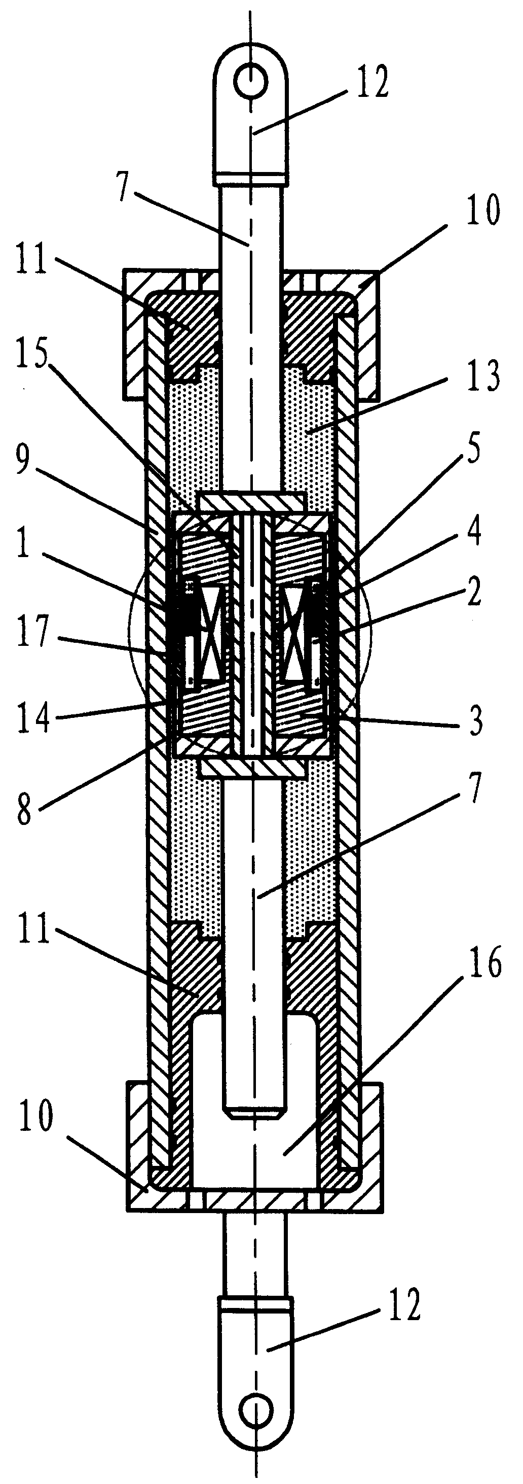
图3是本发明一种形式的逆变型磁流变阻尼器剖视图;Fig. 3 is a sectional view of an inverter magneto-rheological damper in a form of the present invention;
图4是图3中磁路部分的局部放大图;Fig. 4 is a partially enlarged view of the magnetic circuit part in Fig. 3;
图5是图4的A-A截面剖视图;Fig. 5 is the A-A sectional view of Fig. 4;
图6本发明提出的另一种形式的逆变型磁流变阻尼器剖视图;Fig. 6 is a sectional view of another form of inverter magneto-rheological damper proposed by the present invention;
图7是图6中磁路部分的局部放大图;Fig. 7 is a partially enlarged view of the magnetic circuit part in Fig. 6;
图8是图7的A-A截面剖视图;Fig. 8 is the A-A sectional view of Fig. 7;
图9本发明提出的另一种形式的逆变型磁流变阻尼器剖视图;Fig. 9 is a cross-sectional view of another form of inverter magneto-rheological damper proposed by the present invention;
图10是图9中磁路部分的局部放大图;Fig. 10 is a partially enlarged view of the magnetic circuit part in Fig. 9;
图11是图10的A-A截面剖视图;Fig. 11 is the A-A sectional view of Fig. 10;
图12本发明提出的另一种形式的逆变型磁流变阻尼器剖视图;Figure 12 is a sectional view of another form of inverter magnetorheological damper proposed by the present invention;
图13是图12的A-A截面剖视图;Fig. 13 is the A-A sectional view of Fig. 12;
图14现有技术磁流变阻尼器的结构剖视图。Fig. 14 is a structural sectional view of a magneto-rheological damper in the prior art.
图中:In the picture:
1-励磁线圈 11-密封导向装置1-Excitation coil 11-Seal guide device
2-永磁体 12-连接耳环2-Permanent magnet 12-Connecting earrings
3-导磁体 13-磁流变液3-Magnetic body 13-Magneto-rheological fluid
3a-导磁铁芯 14-耐磨活塞套3 a - magnetic core 14 - wear-resistant piston sleeve
3b-导磁芯轴 15-中心连杆3 b - magnetic core shaft 15 - central link
4-工作气隙 16-副缸4-Working air gap 16-Auxiliary cylinder
5-辅助气隙 17-隔磁护套5-Auxiliary air gap 17-Magnetic isolation sheath
6-磁力线 18-旁通管6-Magnetic force line 18-Bypass pipe
7-活塞杆 19-体积补偿腔7-piston rod 19-volume compensation chamber
8-活塞 20-内缸8-piston 20-inner cylinder
9-缸体 21-通液孔9-Cylinder body 21-Liquid hole
10-缸盖 22-旁通缸10-Cylinder head 22-Bypass cylinder
23-端盖与密封
具体实施方式Detailed ways
本发明提出的逆变型磁流变阻尼器除电磁磁路部分外其它结构与现有技术设计的磁流变阻尼器相同。所述的电磁磁路部分如图2所示,电磁磁路中设置有辅助气隙5及永磁体2,合理设置辅助气隙5的大小,可以保证当励磁线圈1没有电流通过时,由永磁体2产生的磁通基本不通过辅助气隙5,而主要由构成阻尼通道的工作气隙4形成回路;当励磁线圈1通过一定方向的电流时,励磁线圈1产生的励磁磁场与永磁磁场通过辅助气隙5形成回路,从而导致永磁体产生的磁场基本不通过构成阻尼通道的工作气隙4,或者在理论上也可以认为励磁磁场在工作气隙4产生了与永磁磁通大小相等,方向相反的磁通,从而使得工作气隙4等效合成磁场为零。这种磁路设计,避免了励磁磁场对永磁体的消磁效应,并且可以有效的实现工作气隙4的磁场逆变。所述的永磁体可采用具有高剩磁和高磁能积的烧结钕铁硼(Nd2Fe14B1)、硬磁铁氧体或钻稀土永磁体等;导磁材料可采用电工软铁、硅钢、铁镍合金或磁性能良好的低碳钢;隔磁材料可采用青铜合金或无磁高强铝合金。The inverter magnetorheological damper proposed by the invention has the same structure as the magnetorheological damper designed in the prior art except for the electromagnetic magnetic circuit. Described electromagnetic magnetic circuit part is shown in Figure 2, is provided with
现有技术的磁流变阻尼器按工作模式不同可分为磁流变阻尼器可以分为流动型(两极板固定,流体流动;阀式)、剪切型(极板有切向相对运动;离合器式)、挤压型(极板有相向相对运动;压缩式)。针对不同的工作模式,本发明所提出的四种具体实施方案如图3~图13所示。Magneto-rheological dampers in the prior art can be divided into flow type (two pole plates are fixed, fluid flows; valve type), shear type (the pole plates have tangential relative motion; Clutch type), extrusion type (the plates have relative movement; compression type). For different working modes, four specific implementation schemes proposed by the present invention are shown in Fig. 3 to Fig. 13 .
如图3所示为本发明提出的一种剪切式逆变型磁流变阻尼器的结构图。阻尼器除电磁磁路部件外与现有技术的磁流变阻尼器无异。在缸体9一端的缸盖10与密封导向装置11之间设置有副缸16,活塞8两端的活塞杆7的一端通过密封导向装置11伸入副缸16内,另一端通过密封装置穿出缸盖。电磁磁路部件位于中部挖槽的活塞8内,如图4、图5所示,磁流变阻尼器的阻尼通道为活塞与缸体之间的间隙,也就是基本磁路中的工作间隙4。当活塞与缸体发生相对运动时,处于活塞和缸体间的磁流变液会产生剪切性流动。活塞中部为联系活塞各部件以及活塞杆的中心连杆15,中心连杆15采用具有足够强度的隔磁材料加工而成;中间挖空的高导磁铁芯3a套于中心连杆15外部,并于活塞中部设有辅助气隙5,辅助气隙为隔磁材料制成的隔磁环;在导磁铁芯3a中部的环形槽内绕制有励磁线圈1,线圈1外圈为嵌装有棒状永磁体2的隔磁材料加工的筒形护套17,棒形的永磁体2均匀嵌装于隔磁护套17中部。在活塞8的两端为具有一定强度的耐磨活塞套筒14,用于保护强度较低的导磁材料不受磁流变液的磨蚀。励磁线圈引线的引出方式与现有技术的磁流变阻尼器相同。FIG. 3 is a structural diagram of a shear-type inverter magneto-rheological damper proposed by the present invention. The damper is the same as the magnetorheological damper in the prior art except for the electromagnetic magnetic circuit components. An
如图6所示为本发明提出的逆变型磁流变阻尼器的另一种流动式实现方式。阻尼器除电磁磁路部件外与现有技术的磁流变阻尼器无异。阻尼器缸体由内缸20和外缸9两部分组成,外缸9上设置有体积补偿腔19,阻尼器一端通过设置于内缸上的通液孔21使得内缸20和外缸9之间的间隙与内缸内部导通。另一端经由工作气隙4使内缸20和外缸9之间的间隙与内缸内部导通。电磁磁路部件位于缸体内一端密封装置内侧,如图7、图8所示,其外侧为圆盘状的导磁体3,中心部分为导磁体铁芯3a,励磁线圈1绕制于导磁体铁芯3a上,导磁体铁芯3a伸出部分与励磁线圈1外的导磁体3伸出部分围成工作气隙4,当活塞与缸体发生相对运动时,会压迫磁流变液使之经由内缸20和外缸9之间的间隙而流过设置于阻尼器一端的工作气隙4产生阻尼力。处于线圈内部的导磁铁芯的一端设有隔磁材料构成的辅助气隙5,一端设置有放射状的永磁体2,永磁体2嵌于隔磁护套17内以避免受力磨损。永磁体2的一个磁极与线圈内部的导磁体铁芯3a紧密连接,另一磁极与线圈外部的导磁体3紧密连接。导磁体3与内缸和外缸连接部位为工作气隙4和通液孔21,合理设置工作气隙4的间隙大小和辅助气隙5的大小,可以保证线圈不通电流时永磁体2激发的磁场大部分由工作气隙4通过。As shown in FIG. 6 , another flow implementation of the inverter magneto-rheological damper proposed by the present invention is shown. The damper is the same as the magnetorheological damper in the prior art except for the electromagnetic magnetic circuit components. The cylinder body of the damper is composed of an
如图9所示为本发明提出的另一种流动式逆变型阻尼器的实现方式。阻尼器除电磁磁路部件外与现有技术的磁流变阻尼器无异。在缸体9一端的缸盖10与密封导向装置11之间设置有副缸16,活塞8两端的活塞杆7的一端通过密封导向装置11伸入副缸16内,另一端通过密封装置穿出缸盖。阻尼器缸体9内部通过通液孔21与旁通缸22相连,阻尼器中的电磁磁路部件设置于旁通缸22内,如图10、图11所示。旁通缸22的中部为导磁材料构成的导磁芯轴3b,芯轴与包裹励磁线圈1的L型的柱状导磁体3之间的间隙为磁场作用的工作气隙4。当阻尼器的活塞8在缸体内运动时,会挤压缸中的磁流变液,使其从通液孔21流经工作气隙4。工作气隙4内磁场发生变化时将引起位于其内的磁流变液发生相态改变而改变阻尼器的阻尼。工作气隙4与励磁线圈1之间设有隔磁护套17,棒形的永磁体2均匀嵌装于筒形隔磁护套17内,励磁线圈1外的中部为隔磁体构成的环形辅助气隙5。As shown in FIG. 9 , another implementation of the flow inverter damper proposed by the present invention is shown. The damper is the same as the magnetorheological damper in the prior art except for the electromagnetic magnetic circuit components. An
如图12所示为本发明提出的一种挤压式逆变型阻尼器的实现方式。阻尼器除电磁磁路部件外与现有技术的磁流变阻尼器无异。缸体两端为端盖与密封装置23,具有一定强度的导磁材料制作的活塞8位于缸体中部,两端连接穿过缸盖伸出缸体的活塞杆7,电磁磁路部件位于密封装置之间的缸体内腔内,如图13所示,工作气隙4为导磁材料3与活塞8之间形成的间隙,当阻尼器活塞8发生小幅度运动时会挤压处于工作气隙4中的磁流变液,使之发生扩散性挤压流动而引起阻尼出力。缸体的内壁为均匀嵌有棒形永磁体2的隔磁护套17,励磁线圈1绕制于隔磁护套17外部,励磁线圈的外部及端部为高磁导率的导磁材料3,并且在线圈的中部位置设置环形隔磁材料构成的辅助气隙5。As shown in FIG. 12 , an implementation of a squeeze-type inverter damper proposed by the present invention is shown. The damper is the same as the magnetorheological damper in the prior art except for the electromagnetic magnetic circuit components. The two ends of the cylinder body are end caps and sealing
前述的各逆变型磁流变阻尼器的其它通用配件采用公知技术确定,阻尼器的缸体内径、活塞杆直径、导磁区长度、导磁间隙大小、阻尼器行程、线圈匝数、永磁体用量、磁流变液的粘度、磁流变液饱和强度、缸体壁厚等按照公知的液压系统设计方法和磁路设计方法计算确定。Other common parts of the above-mentioned inverter type magneto-rheological dampers are determined by known technology. The dosage, the viscosity of the magnetorheological fluid, the saturation strength of the magnetorheological fluid, and the wall thickness of the cylinder body are calculated and determined according to known hydraulic system design methods and magnetic circuit design methods.
这种逆变型磁流变阻尼器可以与普通磁流变阻尼器一样通过连接装置安装在建筑结构产生相对位移的位置或作为汽车减振器、离合器用于悬架减振和速度控制。例如将其安装于框剪结构的层间或建筑结构梁柱节点处时,其工作机理为:当未发生地震时,阻尼器类似于摩擦耗能器协同建筑结构受力,当地震发生时,有传感器采集结构的振动信息和地面的运动信息,并由控制器依据一定的半主动控制算法计算得到磁流变阻尼器所需施加的电流值,并由功率放大装置对阻尼器施加控制指令。当阻尼器的活塞与缸体间有相对位移趋势时,阻尼器即可产生反力以作用于结构,由于阻尼器对运动的阻滞作用减小建筑物的振动,从而实现建筑结构减振控制的目的。This inverter-type magneto-rheological damper can be installed in the position where the relative displacement of the building structure is generated through the connection device like the ordinary magnetorheological damper, or it can be used as an automobile shock absorber and a clutch for suspension vibration reduction and speed control. For example, when it is installed in the interstory of the frame-shear structure or at the beam-column joint of the building structure, its working mechanism is: when no earthquake occurs, the damper is similar to the frictional energy dissipator to cooperate with the building structure to bear the force. When the earthquake occurs, There are sensors to collect the vibration information of the structure and the ground movement information, and the controller calculates the current value required by the magneto-rheological damper according to a certain semi-active control algorithm, and the power amplifier applies control commands to the damper. When there is a relative displacement trend between the piston and the cylinder of the damper, the damper can generate a reaction force to act on the structure, and the vibration of the building can be reduced due to the damper's blocking effect on the movement, thereby realizing the vibration reduction control of the building structure the goal of.
本发明提出的磁流变阻尼器磁路设计亦可有许多变型,都属于本发明所提出的技术方案。The magnetic circuit design of the magneto-rheological damper proposed by the present invention can also have many variations, all of which belong to the technical solution proposed by the present invention.
Claims (5)
Priority Applications (1)
| Application Number | Priority Date | Filing Date | Title |
|---|---|---|---|
| CNB2004100688535A CN100356082C (en) | 2004-07-09 | 2004-07-09 | Inverse type magnetic flow damper |
Applications Claiming Priority (1)
| Application Number | Priority Date | Filing Date | Title |
|---|---|---|---|
| CNB2004100688535A CN100356082C (en) | 2004-07-09 | 2004-07-09 | Inverse type magnetic flow damper |
Publications (2)
| Publication Number | Publication Date |
|---|---|
| CN1587738A CN1587738A (en) | 2005-03-02 |
| CN100356082C true CN100356082C (en) | 2007-12-19 |
Family
ID=34604185
Family Applications (1)
| Application Number | Title | Priority Date | Filing Date |
|---|---|---|---|
| CNB2004100688535A Expired - Fee Related CN100356082C (en) | 2004-07-09 | 2004-07-09 | Inverse type magnetic flow damper |
Country Status (1)
| Country | Link |
|---|---|
| CN (1) | CN100356082C (en) |
Cited By (2)
| Publication number | Priority date | Publication date | Assignee | Title |
|---|---|---|---|---|
| CN101749358B (en) * | 2010-02-24 | 2011-11-30 | 谭晓婧 | Damping force adjustable permanent magnet type magnetic current variable damper |
| WO2013007138A1 (en) * | 2011-07-12 | 2013-01-17 | Beijingwest Industries Co., Ltd. | A double pumper magneto-rheological hydraulic tie bar assembly |
Families Citing this family (41)
| Publication number | Priority date | Publication date | Assignee | Title |
|---|---|---|---|---|
| CN100363643C (en) * | 2006-06-21 | 2008-01-23 | 天津大学 | Multi-stage assembled anti-settling magnetorheological damper |
| CN100455843C (en) * | 2007-06-04 | 2009-01-28 | 湖南大学 | Magneto-rheological tuned liquid column damper |
| CN101215861B (en) * | 2007-12-28 | 2010-09-29 | 天津大学 | Damping force bidirectionally regulating MR damper |
| CN101215860B (en) * | 2007-12-28 | 2010-05-19 | 天津大学 | High output magnetorheological damper |
| DE102008036980A1 (en) * | 2008-08-08 | 2010-02-11 | Robert Bosch Gmbh | Actuator and executed with such a control valve arrangement |
| CN101989803B (en) * | 2009-07-30 | 2013-11-13 | 北京京西重工有限公司 | Magnetorheological fluid-based device comprising magnetorheological piston component |
| CN101709761B (en) * | 2009-12-23 | 2011-07-06 | 重庆仪表材料研究所 | Single outstretch pole magnetorheological damper |
| CN101761146B (en) * | 2010-01-04 | 2011-08-10 | 湖南大学 | Permanent-magnet type eddy current tuned mass damper |
| CN101832355A (en) * | 2010-03-30 | 2010-09-15 | 谭和平 | Double-out-rod adaptive double-control magneto-rheological damper |
| CN101825146B (en) * | 2010-04-27 | 2012-11-28 | 谭和平 | Self-adaptive magnetorheological clutch |
| CN101915283B (en) * | 2010-08-06 | 2011-12-07 | 浙江大学 | Magneto-rheological combined damping control method and device |
| CN102135154A (en) * | 2011-03-18 | 2011-07-27 | 谭和平 | Alnico piston-type magneto-rheological damper with single piston rod |
| CN102182785A (en) * | 2011-03-18 | 2011-09-14 | 谭晓婧 | Magnetic steel piston type magneto-rheological damper with double ejection rods |
| CN102155515A (en) * | 2011-04-19 | 2011-08-17 | 谭和平 | Magnetorheological damper with external electromagnet |
| CN102242791A (en) * | 2011-04-19 | 2011-11-16 | 谭和平 | Magneto-rheological damper of synchronous sliding external electromagnet |
| KR101557909B1 (en) * | 2011-05-17 | 2015-10-06 | 베이징웨스트 인더스트리즈 코포레이션 리미티드 | Magneto-rheological damping assembly |
| JP5821095B2 (en) * | 2011-06-13 | 2015-11-24 | Kyb株式会社 | Magnetorheological fluid shock absorber |
| CN102374330A (en) * | 2011-10-19 | 2012-03-14 | 昆明理工大学 | Magnetorheological valve |
| CN103089906B (en) * | 2013-02-04 | 2015-04-01 | 谢宁 | Crack cylinder single-out rod magneto-rheological damper |
| CN103512624B (en) * | 2013-08-27 | 2016-04-27 | 黑龙江科技大学 | Based on coalcutter cutting resistance method for sensing and the sensor of magnetic rheology elastic body |
| CN103953679B (en) * | 2014-04-28 | 2016-01-20 | 浙大新剑(上海)智能技术有限公司 | A kind of two outstretch pole magnetorheological damper piston assembly and manufacture method thereof |
| CN104763703B (en) * | 2015-02-09 | 2017-01-04 | 浙江大学 | A kind of energy feedback type is magnetorheological-and air supporting is combined executor |
| CN104747649B (en) * | 2015-04-20 | 2017-06-06 | 中国人民解放军装甲兵工程学院 | A kind of MR damper |
| CN105003585B (en) * | 2015-06-12 | 2017-03-01 | 重庆材料研究院有限公司 | Variable cross-section piston magneto-rheological vibroshock |
| CN105156568A (en) * | 2015-07-20 | 2015-12-16 | 常州大学 | Double-rod variable-cylinder-body passive double-control variable-damping magnetorheological damper |
| CN105240444B (en) * | 2015-11-05 | 2017-09-05 | 重庆材料研究院有限公司 | Magneto-rheological vibration damper based on parallel-connection structure |
| CN105735507B (en) * | 2016-03-10 | 2018-01-30 | 苏州科技学院 | A kind of tension and compression type magnetic shape memory alloy Multimode Intelligent damper |
| CN106641081B (en) * | 2016-12-29 | 2018-05-22 | 中国农业大学 | Have the function of that electromagnetism actively removes heavy poly- MR damper and goes heavy poly- method |
| CN106838005B (en) * | 2017-04-11 | 2019-02-05 | 华中科技大学 | A Heteropolar Permanent Magnetic Offset Hybrid Radial Magnetic Bearing |
| CN107084221A (en) * | 2017-05-04 | 2017-08-22 | 西北工业大学 | A Memorable Magnetic Circuit Structure for Magnetorheological Shock Absorbers |
| CN107327533B (en) * | 2017-07-12 | 2019-12-10 | 东南大学 | A magnetorheological mud damper |
| CN108561486A (en) * | 2018-04-23 | 2018-09-21 | 福州大学 | A kind of novel anti-settling magnetic rheological liquid damper |
| CN112696451B (en) * | 2020-01-09 | 2022-09-06 | 北京京西重工有限公司 | Rotary damper assembly |
| CN112324837B (en) * | 2020-11-24 | 2021-10-12 | 清华大学 | Electromagnetic pistons and magnetorheological dampers |
| CN112431891A (en) * | 2020-12-11 | 2021-03-02 | 成都凯驰汽车底盘系统有限公司 | Double-guide non-contact magneto-rheological damper |
| CN114135620A (en) * | 2021-11-13 | 2022-03-04 | 安徽工程大学 | Damper gain device based on magnetic control principle and use method |
| CN114135619A (en) * | 2021-11-13 | 2022-03-04 | 安徽工程大学 | Damping type energy dissipation device repairing device based on magnetic control principle |
| CN116044951A (en) * | 2023-02-02 | 2023-05-02 | 广西科技大学 | Electromagnetic energy-feedback stepped magneto-rheological damper |
| CN116576216A (en) * | 2023-04-11 | 2023-08-11 | 北京航空航天大学 | Magneto-rheological fluid-based aeroengine load-bearing structure and its active variable stiffness device |
| US12269310B2 (en) * | 2023-05-05 | 2025-04-08 | GM Global Technology Operations LLC | Variable suspension spring rates using magnetorheological fluid |
| CN118432344B (en) * | 2023-12-29 | 2025-12-26 | 比亚迪股份有限公司 | Linear motors, vibration damping devices and vehicles |
Citations (7)
| Publication number | Priority date | Publication date | Assignee | Title |
|---|---|---|---|---|
| JPH0253625A (en) * | 1988-08-17 | 1990-02-22 | Kayaba Ind Co Ltd | Electro-magnetic attenuating valve of damper |
| US5492312A (en) * | 1995-04-17 | 1996-02-20 | Lord Corporation | Multi-degree of freedom magnetorheological devices and system for using same |
| US5632361A (en) * | 1994-09-16 | 1997-05-27 | Fichtel & Sachs Ag | Vibration damper, in particular for motor vehicles |
| JPH10304649A (en) * | 1997-04-22 | 1998-11-13 | Ogura Clutch Co Ltd | Electromagnetic hysteresis brake and tension adjusting device using the brake |
| CN1260031A (en) * | 1997-08-04 | 2000-07-12 | 劳德公司 | Magnetroheological fluid device exhibiting settling stability |
| CN1448116A (en) * | 2002-03-28 | 2003-10-15 | 奥托·博克保健有限公司 | Artificial knee joint having one hydraulic vibration damping cylinder |
| CN2725625Y (en) * | 2004-07-09 | 2005-09-14 | 北京工业大学 | Contravariance magnetic rheological damper |
-
2004
- 2004-07-09 CN CNB2004100688535A patent/CN100356082C/en not_active Expired - Fee Related
Patent Citations (7)
| Publication number | Priority date | Publication date | Assignee | Title |
|---|---|---|---|---|
| JPH0253625A (en) * | 1988-08-17 | 1990-02-22 | Kayaba Ind Co Ltd | Electro-magnetic attenuating valve of damper |
| US5632361A (en) * | 1994-09-16 | 1997-05-27 | Fichtel & Sachs Ag | Vibration damper, in particular for motor vehicles |
| US5492312A (en) * | 1995-04-17 | 1996-02-20 | Lord Corporation | Multi-degree of freedom magnetorheological devices and system for using same |
| JPH10304649A (en) * | 1997-04-22 | 1998-11-13 | Ogura Clutch Co Ltd | Electromagnetic hysteresis brake and tension adjusting device using the brake |
| CN1260031A (en) * | 1997-08-04 | 2000-07-12 | 劳德公司 | Magnetroheological fluid device exhibiting settling stability |
| CN1448116A (en) * | 2002-03-28 | 2003-10-15 | 奥托·博克保健有限公司 | Artificial knee joint having one hydraulic vibration damping cylinder |
| CN2725625Y (en) * | 2004-07-09 | 2005-09-14 | 北京工业大学 | Contravariance magnetic rheological damper |
Cited By (3)
| Publication number | Priority date | Publication date | Assignee | Title |
|---|---|---|---|---|
| CN101749358B (en) * | 2010-02-24 | 2011-11-30 | 谭晓婧 | Damping force adjustable permanent magnet type magnetic current variable damper |
| WO2013007138A1 (en) * | 2011-07-12 | 2013-01-17 | Beijingwest Industries Co., Ltd. | A double pumper magneto-rheological hydraulic tie bar assembly |
| US9273751B2 (en) | 2011-07-12 | 2016-03-01 | Beijingwest Industries, Co. Ltd. | Double pumper magneto-rheological hydraulic tie bar assembly |
Also Published As
| Publication number | Publication date |
|---|---|
| CN1587738A (en) | 2005-03-02 |
Similar Documents
| Publication | Publication Date | Title |
|---|---|---|
| CN100356082C (en) | Inverse type magnetic flow damper | |
| CN205260715U (en) | Adopt annular permanent magnet and excitation coil to carry out compound control's magneto rheological damper | |
| CN102121509B (en) | Magnetorheological damper with annular and disc-shaped liquid flow resistance channels simultaneously | |
| CN112805489B (en) | A dual-rod piezoelectric-magnetorheological composite intelligent damper and its control method | |
| Guo et al. | Finite element analysis and simulation evaluation of a magnetorheological valve | |
| CN102782358B (en) | Valve for magnetorheological fluid, method of operating the valve, and shock absorber to which the valve is applied | |
| CN103148159B (en) | Composite actuator and control method thereof | |
| CN104747649B (en) | A kind of MR damper | |
| CN206830715U (en) | Double magnetic fields MR dampers with mixing fluid course | |
| CN105003589B (en) | A kind of built-in magnetorheological valve carries out the MR damper of damping capacity control | |
| CN107191530A (en) | A kind of twin coil piston magneto-rheological liquid shimmy-damper | |
| CN2725625Y (en) | Contravariance magnetic rheological damper | |
| US10393284B2 (en) | Valve device and method | |
| CN102287474A (en) | Self-powered and self-induction magnetorheological damper | |
| CN108561486A (en) | A kind of novel anti-settling magnetic rheological liquid damper | |
| CN206545666U (en) | The twin coil MR damper of effective damping gap length can be extended | |
| CN102606670A (en) | Differential sensing type magnetorheological damper | |
| CN104963986A (en) | Magneto-rheological damper with mixed flow type fluid flowing channel | |
| CN109973580B (en) | A magnetorheological damper suitable for high-speed impact | |
| CN207454650U (en) | A kind of combined type MR vibration damper | |
| CN1108467C (en) | Magnetroheological fluid device exhibiting settling stability | |
| CN103511547A (en) | Self-sensing magnetorheological damper adopting spiral damping channel | |
| CN101215859A (en) | Full damping channel effective magnetorheological damper | |
| CN101215861B (en) | Damping force bidirectionally regulating MR damper | |
| CN107676419A (en) | A kind of self-powered method of magnetic rheological liquid damper self-induction and damper |
Legal Events
| Date | Code | Title | Description |
|---|---|---|---|
| C06 | Publication | ||
| PB01 | Publication | ||
| C10 | Entry into substantive examination | ||
| SE01 | Entry into force of request for substantive examination | ||
| C14 | Grant of patent or utility model | ||
| GR01 | Patent grant | ||
| C17 | Cessation of patent right | ||
| CF01 | Termination of patent right due to non-payment of annual fee |
Granted publication date: 20071219 |