CN100335403C - Dispensing head, method of returning fluid through the dispensing head to the barrel and reducing foam in the process - Google Patents
Dispensing head, method of returning fluid through the dispensing head to the barrel and reducing foam in the process Download PDFInfo
- Publication number
- CN100335403C CN100335403C CNB02817822XA CN02817822A CN100335403C CN 100335403 C CN100335403 C CN 100335403C CN B02817822X A CNB02817822X A CN B02817822XA CN 02817822 A CN02817822 A CN 02817822A CN 100335403 C CN100335403 C CN 100335403C
- Authority
- CN
- China
- Prior art keywords
- fluid
- dispensing head
- poppet valve
- staving
- unit
- Prior art date
- Legal status (The legal status is an assumption and is not a legal conclusion. Google has not performed a legal analysis and makes no representation as to the accuracy of the status listed.)
- Expired - Lifetime
Links
Images


Classifications
-
- B—PERFORMING OPERATIONS; TRANSPORTING
- B67—OPENING, CLOSING OR CLEANING BOTTLES, JARS OR SIMILAR CONTAINERS; LIQUID HANDLING
- B67D—DISPENSING, DELIVERING OR TRANSFERRING LIQUIDS, NOT OTHERWISE PROVIDED FOR
- B67D7/00—Apparatus or devices for transferring liquids from bulk storage containers or reservoirs into vehicles or into portable containers, e.g. for retail sale purposes
- B67D7/06—Details or accessories
- B67D7/78—Arrangements of storage tanks, reservoirs or pipe-lines
-
- B—PERFORMING OPERATIONS; TRANSPORTING
- B67—OPENING, CLOSING OR CLEANING BOTTLES, JARS OR SIMILAR CONTAINERS; LIQUID HANDLING
- B67D—DISPENSING, DELIVERING OR TRANSFERRING LIQUIDS, NOT OTHERWISE PROVIDED FOR
- B67D7/00—Apparatus or devices for transferring liquids from bulk storage containers or reservoirs into vehicles or into portable containers, e.g. for retail sale purposes
- B67D7/02—Apparatus or devices for transferring liquids from bulk storage containers or reservoirs into vehicles or into portable containers, e.g. for retail sale purposes for transferring liquids other than fuel or lubricants
- B67D7/0288—Container connection means
- B67D7/0294—Combined with valves
-
- B—PERFORMING OPERATIONS; TRANSPORTING
- B05—SPRAYING OR ATOMISING IN GENERAL; APPLYING FLUENT MATERIALS TO SURFACES, IN GENERAL
- B05C—APPARATUS FOR APPLYING FLUENT MATERIALS TO SURFACES, IN GENERAL
- B05C11/00—Component parts, details or accessories not specifically provided for in groups B05C1/00 - B05C9/00
- B05C11/10—Storage, supply or control of liquid or other fluent material; Recovery of excess liquid or other fluent material
-
- B—PERFORMING OPERATIONS; TRANSPORTING
- B67—OPENING, CLOSING OR CLEANING BOTTLES, JARS OR SIMILAR CONTAINERS; LIQUID HANDLING
- B67D—DISPENSING, DELIVERING OR TRANSFERRING LIQUIDS, NOT OTHERWISE PROVIDED FOR
- B67D1/00—Apparatus or devices for dispensing beverages on draught
- B67D1/0042—Details of specific parts of the dispensers
- B67D1/0043—Mixing devices for liquids
- B67D1/0054—Recirculation means
-
- F—MECHANICAL ENGINEERING; LIGHTING; HEATING; WEAPONS; BLASTING
- F16—ENGINEERING ELEMENTS AND UNITS; GENERAL MEASURES FOR PRODUCING AND MAINTAINING EFFECTIVE FUNCTIONING OF MACHINES OR INSTALLATIONS; THERMAL INSULATION IN GENERAL
- F16L—PIPES; JOINTS OR FITTINGS FOR PIPES; SUPPORTS FOR PIPES, CABLES OR PROTECTIVE TUBING; MEANS FOR THERMAL INSULATION IN GENERAL
- F16L37/00—Couplings of the quick-acting type
- F16L37/28—Couplings of the quick-acting type with fluid cut-off means
- F16L37/38—Couplings of the quick-acting type with fluid cut-off means with fluid cut-off means in only one of two pipe-end fittings
- F16L37/40—Couplings of the quick-acting type with fluid cut-off means with fluid cut-off means in only one of two pipe-end fittings with a lift valve being opened automatically when the coupling is applied
- F16L37/42—Couplings of the quick-acting type with fluid cut-off means with fluid cut-off means in only one of two pipe-end fittings with a lift valve being opened automatically when the coupling is applied the valve having an axial bore communicating with lateral apertures
-
- Y—GENERAL TAGGING OF NEW TECHNOLOGICAL DEVELOPMENTS; GENERAL TAGGING OF CROSS-SECTIONAL TECHNOLOGIES SPANNING OVER SEVERAL SECTIONS OF THE IPC; TECHNICAL SUBJECTS COVERED BY FORMER USPC CROSS-REFERENCE ART COLLECTIONS [XRACs] AND DIGESTS
- Y10—TECHNICAL SUBJECTS COVERED BY FORMER USPC
- Y10T—TECHNICAL SUBJECTS COVERED BY FORMER US CLASSIFICATION
- Y10T137/00—Fluid handling
- Y10T137/8593—Systems
- Y10T137/85954—Closed circulating system
-
- Y—GENERAL TAGGING OF NEW TECHNOLOGICAL DEVELOPMENTS; GENERAL TAGGING OF CROSS-SECTIONAL TECHNOLOGIES SPANNING OVER SEVERAL SECTIONS OF THE IPC; TECHNICAL SUBJECTS COVERED BY FORMER USPC CROSS-REFERENCE ART COLLECTIONS [XRACs] AND DIGESTS
- Y10—TECHNICAL SUBJECTS COVERED BY FORMER USPC
- Y10T—TECHNICAL SUBJECTS COVERED BY FORMER US CLASSIFICATION
- Y10T137/00—Fluid handling
- Y10T137/8593—Systems
- Y10T137/86292—System with plural openings, one a gas vent or access opening
- Y10T137/86324—Tank with gas vent and inlet or outlet
- Y10T137/86332—Vent and inlet or outlet in unitary mounting
Landscapes
- Engineering & Computer Science (AREA)
- Mechanical Engineering (AREA)
- General Engineering & Computer Science (AREA)
- Coating Apparatus (AREA)
- Closures For Containers (AREA)
- Containers And Packaging Bodies Having A Special Means To Remove Contents (AREA)
- Loading And Unloading Of Fuel Tanks Or Ships (AREA)
- Quick-Acting Or Multi-Walled Pipe Joints (AREA)
- Lift Valve (AREA)
- Filling Of Jars Or Cans And Processes For Cleaning And Sealing Jars (AREA)
- Devices For Dispensing Beverages (AREA)
- Details Of Rigid Or Semi-Rigid Containers (AREA)
Abstract
Description
本申请要求2001年7月12日申请的、在此引用作为参考的美国临时申请60/305061的优先权。This application claims priority to US
〔技术领域〕〔Technical field〕
本发明涉及一种配件,具体地说,本发明涉及一种可输送腐蚀和高纯净流体且具有多个流动通道的分配头。The present invention relates to a fitting and, more particularly, to a dispensing head capable of delivering corrosive and high purity fluids and having multiple flow channels.
〔背景技术〕〔Background technique〕
在半导体加工、制药和化学品制造工业中,使用高纯净、高侵蚀和/或高腐蚀性液体。出于安全和质量方面的考虑,必须将这些液体装在高可靠和完整的容器及分配系统中。用于输送这些液体的连接件、管和配件必须由高惰性材料制成。人们发现含氟聚合物适合于在这些环境中使用。管通常由PFA制成,配件、阀元件和分配头可由如PFA和PTFE这样的元件及其它含氟聚合物构成。用于输送这些液体的容器通常为高纯净聚乙烯制成的塑料桶,例如确定转让给Fluoroware,Inc.的美国专利No.6045000中所描述的,Fluoroware,Inc.是本发明所有者的前任公司。转让给FSI Corporation的美国专利US4699298和确定转让给Fluoroware,Inc.的美国专利US5108015都对适合于与这些桶一起使用的分配头进行了描述。在此引用上述三个专利作为参考。In the semiconductor processing, pharmaceutical and chemical manufacturing industries, high purity, highly aggressive and/or highly corrosive liquids are used. For safety and quality reasons, these liquids must be contained in highly reliable and integral containers and dispensing systems. Connections, pipes and fittings used to convey these liquids must be made of highly inert materials. Fluoropolymers have been found suitable for use in these environments. Tubing is usually made of PFA and fittings, valve elements and dispense heads can be constructed of elements such as PFA and PTFE and other fluoropolymers. The containers used to deliver these liquids are typically plastic drums made of high purity polyethylene, such as that described in U.S. Patent No. 6,045,000 assigned to Fluoroware, Inc., the predecessor company of the owner of the present invention . US Patent No. 4,699,298 assigned to FSI Corporation and U.S. Patent No. 5,108,015 assigned to Fluoroware, Inc. both describe dispensing heads suitable for use with these barrels. The above three patents are incorporated herein by reference.
桶通常具有桶口,桶口带有桶体插件,桶体插件包括连接到向上的同心连接套上的下向孔管道部分。盖装在桶口和桶体插件上,以便于运输或储藏桶。上述的分配头与插件相连接,并具有连接到连接套上并与其密封接合的主流体通道。Kegs typically have a bung mouth with a bung insert comprising a downwardly facing conduit section connected to an upwardly concentric connecting sleeve. Caps fit over mouth and body inserts for easy transport or storage of drums. The above-mentioned dispensing head is connected to the insert and has a main fluid channel connected to and sealingly engaged with the connecting sleeve.
在某些应用场合,当从桶上卸下分配头时,需要自动切断主流体通道中经过分配头的流体流。这通常是通过一个设置在中心的弹簧加载的提升阀来完成的,在将分配头连接到桶体插件上时,提升阀下降到开启位置。在卸下分配头时,这种提升阀闭合,并因此而避免在卸下分配头时分配头和主管道中的流体发生溢出。这种分配头通常具有一个与中心支座元件相接触的轴向接合部分,中心支座元件由多个辐条支承在插件的主流体通道中间。该结构允许流体在辐条之间流动。虽然辐条和中心支座元件干扰并限制了主流体流,但这种结构机械工作状态良好。In some applications, it is desirable to automatically shut off fluid flow through the dispense head in the main fluid channel when the dispense head is removed from the barrel. This is usually accomplished with a centrally located, spring-loaded poppet valve that drops to the open position when the dispense head is attached to the barrel insert. When the distribution head is removed, this poppet valve is closed and thus prevents the fluid in the distribution head and the main line from escaping when the distribution head is removed. Such dispensing heads generally have an axial engagement portion in contact with a central support member which is supported by a plurality of spokes in the middle of the main fluid passage of the insert. This structure allows fluid to flow between the spokes. The structure works well mechanically, although the spokes and center standoff elements interfere with and restrict the primary fluid flow.
分配头通常具有通气孔,以便于允许排出流体由经过连接在分配头配件上的第二管道供应的气体来代替。分配头还可具有密封检验结构。分配头通常具有多个密封到桶体插件和桶口上的同心O形环。密封检验结构构成位于分配头上的一个配件,该配件与相邻的O形环之间的封闭腔相连。分配头中具有多个通道限制了主流体通道和提升阀所用的空间。因此,流量比理想的要小。The dispense head typically has a vent hole in order to allow the exhaust fluid to be replaced by gas supplied through a second conduit connected to the dispense head fitting. The dispensing head can also have a leak-proof structure. Dispensing heads typically have multiple concentric O-rings that seal to the barrel insert and barrel mouth. The seal proof structure constitutes a fitting on the dispensing head which is connected to the closed cavity between adjacent O-rings. Having multiple channels in the dispense head limits the space available for the main fluid channels and poppet valves. Therefore, the flow rate is smaller than ideal.
在很多应用场合,需要使所分配的流体回流到桶体中。这通常是通过设置在桶体的第二桶口上的第二分配头来实现的。流体回流通常会产生泡沫,泡沫会产生一系列的问题,例如泡沫进入通气孔并可能使分配头和气体注入管道的正常干燥区域发生阻塞或污染,以及在流体液位较低时难于使桶倒空。In many applications, it is desirable to return the dispensed fluid to the barrel. This is usually achieved by a second dispensing head arranged on the second mouth of the barrel. Fluid backflow often creates foam, which can create a host of problems such as foam getting into the vent and potentially blocking or contaminating the normally dry areas of the dispense head and gas injection tubing, and making it difficult to pour the drum when the fluid level is low null.
总之,回流结构是需要的。在可进行提升切断控制的分配头中需要有较高的流动容量。在具有回流管道的桶上,设置防泡沫机构是有益的。In short, a reflow structure is required. Higher flow capacities are required in dispense heads where lift cutoff control is possible. On drums with a return line, it is beneficial to have an anti-foam mechanism.
〔发明内容〕[Content of invention]
本发明的第一方面提供一种可连接到桶体插件上的分配头,该分配头主要由含氟聚合物构成,并包括:一个具有提升阀的主流体流动通道;该提升阀具有:一个环形接合部分和多个轴向支承件,该环形接合部分具有敞开的中心区域,所述支承件支承着接合部分;多个在支承件之间延伸的流体流动通道,以便于与该敞开的中心区域流体连通;多个位于环形接合部分末端的翅片状导向件;其中,提升阀布置成与桶体插件上的连接套相对,并形成经过环形接合部分的敞开的中心区域的主流体分配通道,以提高流量。A first aspect of the present invention provides a dispensing head connectable to a barrel insert, the dispensing head being constructed essentially of fluoropolymer and comprising: a primary fluid flow passage having a poppet valve; the poppet valve having: a an annular joint portion and a plurality of axial supports, the annular joint portion having an open central region, the supports supporting the joint portion; a plurality of fluid flow passages extending between the supports so as to communicate with the open center Area fluid communication; a plurality of fin-like guides at the end of the annular joint; where the poppet valve is positioned opposite the sleeve on the barrel insert and forms the main fluid distribution channel through the open central area of the annular joint , to increase traffic.
本发明的第二方面提供一种分配系统,其包括:可连接到桶体的桶体插件上的分配头;该桶体插件具有一个向桶体底部延伸的下管和一个连接套;该分配头具有与下管流体连通的第一流体分配通道;和一个设置在第一流体分配通道中的提升阀,提升阀包括一个环形接合元件和多个支承件,该环形接合元件适合于与连接套相接合,该支承件将接合元件连接到密封部分上。A second aspect of the present invention provides a dispensing system comprising: a dispensing head connectable to a barrel insert of the barrel; the barrel insert has a down tube extending toward the bottom of the barrel and a connecting sleeve; the dispensing The head has a first fluid distribution channel in fluid communication with the lower tube; and a poppet valve disposed in the first fluid distribution channel, the poppet valve includes an annular engaging element and a plurality of bearings, the annular engaging element is adapted to connect with the connecting sleeve In engagement, the support connects the engagement element to the sealing portion.
本发明的第三方面提供一种用于分配头的提升阀,该分配头构造成可与桶体插件相连接,该分配头主要由含氟聚合物构成,该桶体插件包括一个具有多个向内延伸的凸块的连接套,该提升阀包括:一个环形接合元件,其适合于与连接套的向内延伸凸块相接合;一个密封部分,在关闭提升阀时,其基本上可封闭住流体流;多个位于环形接合元件末端的翅片状元件;多个支承件,其用于将接合元件连接到密封部分上,以构成一个敞开的中心区域;多个流体流动通道,其位于多个支承件之间并与提升阀的敞开的中心区域连通,且适合于提供一个在提升阀开启时穿过提升阀的流体流动通道;以及用于向关闭位置偏压提升阀的装置,从而当分配头固定到桶体插件上时,提升阀就开启,而当分配头从桶体插件上卸下时,提升阀就自行关闭。A third aspect of the present invention provides a poppet valve for use in a dispensing head configured to be connectable to a barrel insert, the dispensing head consisting essentially of fluoropolymer, the barrel insert comprising a The connecting sleeve of the inwardly extending projection, the poppet valve includes: an annular engagement member adapted to engage with the inwardly extending projection of the connecting sleeve; a sealing portion, which is substantially closable when the poppet valve is closed fluid flow; a plurality of fin-shaped elements located at the end of the annular engagement element; a plurality of supports for connecting the engagement element to the sealing portion to form an open central area; a plurality of fluid flow channels located at a plurality of supports communicating between and with the open central region of the poppet valve and adapted to provide a fluid flow passage through the poppet valve when the poppet valve is open; and means for biasing the poppet valve toward a closed position, whereby When the dispensing head is fixed on the barrel insert, the poppet valve opens, and when the dispensing head is removed from the barrel insert, the poppet valve closes itself.
本发明的第四方面提供一种使流体经分配头回流到桶体中的方法,该方法包括以下的步骤:将桶体插件插入到桶体中,并将分配头插入到桶体插件中,桶体插件包括一个连接套;在分配头中,包括主流体通道、回流流体通道和通气通道;将提升阀插入到主流体通道中,提升阀包括一个适合于与连接套相接合的环形接合元件、一个密封部分、多个用于将接合元件连接到密封部分上并在其之间具有多个轴向流体流动通道的支承件、多个用于引导提升阀通过主流体通道的翅片状导向件以及用于向关闭位置偏压提升阀的装置,从而通过将分配头插入到桶体插件上而开启提升阀;将气体通过通气通道排入和排出桶体,以补偿桶体中排液量。A fourth aspect of the present invention provides a method for returning fluid to the barrel through a dispensing head, the method comprising the following steps: inserting a barrel insert into the barrel, and inserting the dispensing head into the barrel insert, The barrel insert includes a connecting sleeve; in the distribution head, it includes the main fluid channel, the return fluid channel and the vent channel; the poppet valve is inserted into the main fluid channel, and the poppet valve includes an annular engagement element suitable for engaging with the connecting sleeve , a sealing part, a plurality of bearings for connecting the engagement element to the sealing part with a plurality of axial fluid flow passages therebetween, a plurality of fin-like guides for guiding the poppet valve through the main fluid passage components and means for biasing the poppet valve towards the closed position, thereby opening the poppet valve by inserting the dispensing head onto the barrel insert; venting gas into and out of the barrel through the vent channel to compensate for the amount of liquid drained from the barrel .
本发明的第五方面提供一种可连接到桶体插件上的分配头,该分配头主要由含氟聚合物构成,并包括:一个具有提升阀的主流体流动通道;提升阀包括用于向关闭位置偏压提升阀的装置,从而通过将分配头插入到桶体插件中而使提升阀开启;一个回流流体通道;一个通气通道;和一个泡沫减少元件,其与回流流体通道流体连通,以减少流体回流到桶体中时产生的泡沫。A fifth aspect of the present invention provides a dispensing head connectable to a barrel insert, the dispensing head consisting essentially of a fluoropolymer, and comprising: a primary fluid flow passage having a poppet valve; means for biasing the poppet valve in the closed position so that the poppet valve is opened by inserting the dispensing head into the barrel insert; a return fluid passage; a vent passage; and a foam reducing element in fluid communication with the return fluid passage to Reduces foaming when fluid flows back into the barrel.
本发明的第六方面提供一种在使液体经分配头回流到桶体中时减少泡沫的方法,该方法包括以下的步骤:将桶体插件插入到桶体中,并将分配头插入到桶体插件中;在分配头中,包括主流体通道、回流流体通道和通气通道;将提升阀插入到主流体通道中,提升阀包括多个轴向支承件,其连接到环形接合元件上,从而形成多个轴向流体流动通道和一个中心流体流动区域,以便于流体在提升阀处于开启位置时流过提升阀,以及用于向关闭位置偏压提升阀的装置,从而通过将分配头插入到桶体插件上而开启提升阀;将泡沫减少元件设置在分配头和桶体插件之间并与回流流体通道流体连通;将气体通过通气通道排入和排出桶体,以补偿桶体中排液量。A sixth aspect of the present invention provides a method of reducing foam when returning liquid to a barrel through a dispensing head, the method comprising the steps of: inserting a barrel insert into the barrel, and inserting the dispensing head into the barrel In the body insert; in the distribution head, including the main fluid channel, the return fluid channel and the vent channel; the poppet valve is inserted into the main fluid channel, the poppet valve includes a plurality of axial supports, which are connected to the annular joint element, so that A plurality of axial fluid flow passages and a central fluid flow region are formed to facilitate fluid flow through the poppet valve when the poppet valve is in the open position, and means for biasing the poppet valve toward the closed position so that by inserting the dispense head into the The poppet valve is opened on the barrel insert; the foam reduction element is arranged between the dispensing head and the barrel insert and is in fluid communication with the return flow channel; the gas is discharged into and out of the barrel through the vent channel to compensate for liquid draining in the barrel quantity.
本发明的第七方面提供一种用于分配头的提升阀,该分配头构成成可与桶体插件相连接,该分配头主要由含氟聚合物构成,该桶体插件包括一个连接套,该提升阀包括:一个环形接合元件,其适合于与连接套相接合;多个位于环形接合元件末端的翅片状元件;多个连接到环形接合元件上的支承件,其形成多个与提升阀的敞开的中心区域流体连通的轴向流体流动通道;以及一个延伸到敞开的中心区域的锥形元件,其适合于进一步引导流体流过该流体流动通道。A seventh aspect of the present invention provides a poppet valve for a dispensing head, the dispensing head is configured to be connectable to a barrel insert, the dispensing head is mainly composed of fluoropolymer, the barrel insert includes a connecting sleeve, The poppet valve comprises: an annular engagement element adapted to engage with a connecting sleeve; a plurality of fin-shaped elements positioned at the end of the annular engagement element; a plurality of supports connected to the annular engagement element forming a plurality of an axial fluid flow passage in fluid communication with the open central region of the valve; and a tapered member extending to the open central region adapted to further direct fluid flow through the fluid flow passage.
流体分配系统包括一个带有桶口的桶体、一个桶体插件和一个分配头,桶体插件包括插入到桶口中的下管,分配头与下管相连,并具有超过已知分配头的增强功能特征。在一个优选实施例中,分配头具有可将回流流体排泄到桶体插件下管周围的环形空间中的回流管线。泡沫限制装置进行工作可使回流过程中产生的泡沫最少或使其减少。在一个优选实施例中,弹簧加载的提升阀可控制经过分配头的主流体通道,在从桶口上卸下分配头时,提升阀关闭。提升阀的结构设置成这样,接合元件是一个环形元件,其具有沿轴向延伸的支承件,该环形元件安置在桶体插件的连接套上并与其相连接。连接套具有支座部分,并包括向内延伸的凸块以便与提升阀的接合元件相接合。在进行接合时,分配头和桶体插件一起具有一个基本上敞开的主通道,且唯一的障碍是向内延伸的凸块。这种结构便于液体从桶体到分配头自由地进行大容量流动。The fluid dispensing system includes a barrel with a mouth, a barrel insert and a dispensing head, the barrel insert including a down tube inserted into the mouth of the barrel, the dispensing head is connected to the down tube and has enhancements over known dispensing heads functional characteristics. In a preferred embodiment, the dispense head has a return line that drains return fluid into the annular space around the barrel insert downtube. The foam restriction operates to minimize or reduce foam generation during reflow. In a preferred embodiment, a spring loaded poppet valve controls the passage of the primary fluid through the head, the poppet valve being closed when the head is removed from the mouth of the barrel. The poppet valve is constructed in such a way that the engagement element is an annular element with an axially extending support, which is placed on and connected to the connecting sleeve of the barrel insert. The coupling sleeve has a seat portion and includes inwardly extending projections for engagement with the engagement member of the poppet valve. When engaged, the dispensing head and barrel insert together have a substantially open main channel with the only obstructions being the inwardly extending tabs. This structure facilitates the free flow of large volumes of liquid from the barrel to the dispensing head.
本发明优选实施例的特点是,与普通分配头和提升阀相比,本发明提升阀结构的流体流量较大。A feature of the preferred embodiment of the present invention is that the poppet valve structure of the present invention provides greater fluid flow compared to conventional dispense heads and poppet valves.
本发明优选实施例的特点和优点是,与类似的回流系统相比,回流流体产生的泡沫减少。A feature and advantage of a preferred embodiment of the present invention is that the return fluid generates less foam than a similar return system.
本发明优选实施例的特点和优点是,流体可经用于分配流体的相同分配头回流到桶体中。A feature and advantage of the preferred embodiment of the present invention is that the fluid can be returned to the barrel through the same dispensing head used to dispense the fluid.
本发明优选实施例的特点和优点是,在分配头上设有用于检验分配头O形环的密封完整性的密封检验结构。A feature and advantage of a preferred embodiment of the present invention is that there is a seal verification structure on the dispense head for verifying the seal integrity of the dispense head O-ring.
〔附图说明〕[Description of drawings]
图1是本发明分配头的透视图。Figure 1 is a perspective view of the dispensing head of the present invention.
图2是本发明的流体分配系统的透视图。Figure 2 is a perspective view of the fluid dispensing system of the present invention.
图3是图1所示分配头的分解图。Figure 3 is an exploded view of the dispensing head shown in Figure 1 .
图4是图1所示分配头的顶部平面图。Figure 4 is a top plan view of the dispensing head shown in Figure 1 .
图5是图1所示分配头沿图4的5-5剖视的横截面图,其示出了与桶体插件分离开的分配头。5 is a cross-sectional view of the dispensing head shown in FIG. 1 taken along line 5-5 of FIG. 4 showing the dispensing head separated from the barrel insert.
图6是图1所示分配头沿图4的5-5剖视的横截面图,其示出了连接到桶体插件上的分配头。Fig. 6 is a cross-sectional view of the dispensing head shown in Fig. 1 taken along line 5-5 of Fig. 4, showing the dispensing head connected to the barrel insert.
图7是图1所示分配头沿图4的6-6剖视的横截面图。7 is a cross-sectional view of the dispensing head shown in FIG. 1 taken along line 6-6 in FIG. 4 .
图8是图3所示透视桶体插件的平面图。Fig. 8 is a plan view of the see-through barrel insert shown in Fig. 3 .
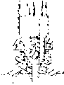
图9是本发明的提升阀的正视图。Fig. 9 is a front view of the poppet valve of the present invention.
图10是提升阀的透视图。Figure 10 is a perspective view of a poppet valve.
图11是分配头的顶部部分沿图6的11-11剖视的横截面图。11 is a cross-sectional view of the top portion of the dispensing head taken along line 11-11 of FIG. 6 .
〔具体实施方式〕〔Detailed ways〕
如图1和2所示,图示的流体分配系统通常包括桶体20、桶体插件22和分配头24。桶体20通常由通过吹模法形成的多层聚乙烯制成。对于本申请,术语分配头应当认为还包括流体回流头。As shown in FIGS. 1 and 2 , the illustrated fluid dispensing system generally includes a
桶体插件包括桶口连接部件30和下管32。图3、4、5、6和7示出了分配头和桶体插件的详细结构。分配头包括本体部分40,本体部分40包括上部42和下部44。多个配件46设置在上部42的顶部,并利用普通的连接件例如用于连接管最好是PFA管的Flaretek连接件连接到分配头上。配件可连接到主流体通道50、回流流体通道52、通气通道54和密封检验通道56上。图11示出了这些通道,图11是图6沿11-11的横截面图。The barrel insert includes a barrel
上部42通过形成各个内部通道的整体壁部分60适当隔开。分配头本体部分的上部42可通过Purebonded方式与下部44进行连接。授予Michael Osgar并指明转让给本发明的所有人Fluoroware,Inc.的美国专利US4929293就描述了对管端进行Purebonding连接的方法。这里作为参考对该专利进行引用。The
提升阀70、O形环72和塑料弹簧74设置在下部的中心腔64中。当提升阀70闭合时,O形环72与提升阀70和整体壁60相接合并与其形成密封。塑料弹簧74向闭合位置偏压提升阀70,并通过扣环76固定就位。在装配好后,提升阀70、O形环72、弹簧74和扣环76如图5所示进行布置。图5所示的提升阀70处于闭合密封位置,其中,分配头24还未完全与桶体插件22相啮合。A
图9和10示出了提升阀70的详细结构。O形环72在提升阀的中间部分82围绕密封部分80延伸。第一端部86包括构造成环状的接合部分88。支承件90从接合部分延伸到中间部分82。多个导向件94和一个中心导向件95从第二端部96伸出,以便可滑动地将提升阀保持在分配头24的中心腔64中。弹簧74与第二端部96相接合,并在提升阀70和扣环76之间受到压缩,如图7所示,扣环76适当地固定在扣环槽102中。重要的是,提升阀具有敞开的中心区域106,以允许流体流入到桶体插件的连接套112中。锥形部分108在密封部分80附近向下延伸到敞开的中心区域106。9 and 10 show the detailed structure of the
如图3和8所示,桶体插件22支承着向上延伸的连接套112。桶体插件22具有中心流体流动通道130,通道130与分配头24上的主流体分配通道52相连。多个环形回流通道132与分配头24的回流通道50相连。多个通气通道136与分配头24的通气通道54相连。密封表面设置在桶体插件的每个通道中间,以便如图3、5和6所示与O形环138密封接合。下管连接套112可具有向内延伸的凸块150,以便于与提升阀的环形接合部分88接合。下管32还具有多个键块160,以确保通过设置在键块元件166上相应的键块164与合适的分配头24相连接,而键块元件166连接在分配头24的本体部分上。另外,螺母180可转动地与桶体插件22相啮合,以便于将分配头24固定连接到桶体插件22上。As shown in FIGS. 3 and 8 , the
图1和7示出了泡沫减少元件192。泡沫减少元件192围绕桶体插件22的下管32并与其相连接。泡沫减少元件192包括壁部分205、漏斗形部分208和排泄部分210。壁部分205和漏斗形部分208形成一个泡沫减少腔212,泡沫减少腔212上设有通气孔216。泡沫减少元件192接收来自回流通道52经过分配头24然后再经过桶体插件22流回的回流流体。在回流流体与桶体20中的剩余流体接触之前,回流流体通常会开始起沫。泡沫减少元件192可减小回流流体的速度,并围绕下管32排泄流体,从而对回流流体产生稳定效应。泡沫减少元件192具有叉形头230,其可接合在通过Purebond焊接制成的下管32上的焊道250的上方。1 and 7 illustrate
泡沫减少腔212使气体与泡沫分离并通过通气孔216排出,同时液体部分通常以稳定的层流方式向下流动。这就避免了出现更多紊流,如果流体直接从桶体插件22排入桶体20并排出到桶体20内的流体面顶部,就会形成紊流。
因此,本发明由上述的部件构成,这些部件可单独地用于分配头或流体回流头中。对于本申请,流体回流头应包括在术语分配头中。Thus, the invention consists of the above-mentioned components, which can be used individually in a dispensing head or in a fluid return head. For this application, fluid return head shall be included in the term dispenser head.
在不脱离本发明任何必要特征的精神的情况下,本发明可以其它特定的方式来实现。因此,所述实施例在其各个方面都应当被认为是示例性的而不是限制性的,应当指出,是所附的权利要求书而不是前述的说明书表明了本发明的保护范围。The present invention may be carried out in other specific ways without departing from the spirit of any of the essential features of the invention. Accordingly, the described embodiments should be considered in all respects as illustrative rather than restrictive, with the appended claims rather than the foregoing specification indicating the scope of the invention.
Claims (38)
Applications Claiming Priority (2)
| Application Number | Priority Date | Filing Date | Title |
|---|---|---|---|
| US30506101P | 2001-07-12 | 2001-07-12 | |
| US60/305,061 | 2001-07-12 |
Publications (2)
| Publication Number | Publication Date |
|---|---|
| CN1608029A CN1608029A (en) | 2005-04-20 |
| CN100335403C true CN100335403C (en) | 2007-09-05 |
Family
ID=23179152
Family Applications (1)
| Application Number | Title | Priority Date | Filing Date |
|---|---|---|---|
| CNB02817822XA Expired - Lifetime CN100335403C (en) | 2001-07-12 | 2002-07-11 | Dispensing head, method of returning fluid through the dispensing head to the barrel and reducing foam in the process |
Country Status (6)
| Country | Link |
|---|---|
| US (1) | US6955185B2 (en) |
| EP (1) | EP1404610A4 (en) |
| JP (2) | JP4474160B2 (en) |
| KR (1) | KR100905569B1 (en) |
| CN (1) | CN100335403C (en) |
| WO (1) | WO2003006359A2 (en) |
Families Citing this family (26)
| Publication number | Priority date | Publication date | Assignee | Title |
|---|---|---|---|---|
| US7025234B2 (en) * | 2001-10-20 | 2006-04-11 | Advanced Technology Materials, Inc. | Apparatus and method for dispensing high-viscosity liquid |
| ATE342223T1 (en) * | 2003-08-12 | 2006-11-15 | Sfc Smart Fuel Cell Ag | LOCKING DEVICE FOR FUEL TANKS |
| JP4441289B2 (en) * | 2004-02-25 | 2010-03-31 | シスメックス株式会社 | Liquid suction device |
| US20060108371A1 (en) * | 2004-04-18 | 2006-05-25 | Rauworth Barry L | Blow-molded drum |
| US7546857B2 (en) | 2004-05-06 | 2009-06-16 | Colder Products Company | Connect/disconnect coupling for a container |
| FR2872492B1 (en) * | 2004-07-02 | 2006-10-20 | Flextainer Sa | BONDE ASSEMBLY AND TAP FOR SMALL CONTAINERS PROVIDED WITH AT LEAST ONE MEANS OF POSITIONING AND HOLDING |
| US7760104B2 (en) * | 2005-04-08 | 2010-07-20 | Entegris, Inc. | Identification tag for fluid containment drum |
| US7806151B2 (en) * | 2005-04-08 | 2010-10-05 | Entegris, Inc. | Drum cap venting device |
| TWI401203B (en) * | 2005-04-08 | 2013-07-11 | Entegris Inc | High-volume fluid dispense system |
| US8561855B2 (en) | 2005-04-08 | 2013-10-22 | Entegris, Inc. | High-volume fluid dispense system |
| US8753097B2 (en) * | 2005-11-21 | 2014-06-17 | Entegris, Inc. | Method and system for high viscosity pump |
| US8016000B2 (en) | 2006-04-19 | 2011-09-13 | W. R. Grace & Co.-Conn. | Processes and systems for transferring particulate substances from containers |
| CN101600644B (en) * | 2006-07-11 | 2014-08-13 | 考尔得产品公司 | Connect/disconnect coupling for a container |
| JP5364273B2 (en) * | 2008-01-28 | 2013-12-11 | サーパス工業株式会社 | Plug structure |
| DE102008047759A1 (en) * | 2008-09-17 | 2010-03-25 | AFRISO Euro-Index GmbH für Sicherungsarmaturen und Füllstandsmessung | Tank armature device for liquid container of a container battery |
| JP5595712B2 (en) * | 2009-11-04 | 2014-09-24 | サーパス工業株式会社 | Socket structure |
| US8684705B2 (en) | 2010-02-26 | 2014-04-01 | Entegris, Inc. | Method and system for controlling operation of a pump based on filter information in a filter information tag |
| US8727744B2 (en) * | 2010-02-26 | 2014-05-20 | Entegris, Inc. | Method and system for optimizing operation of a pump |
| JP4713676B1 (en) * | 2010-08-11 | 2011-06-29 | サーパス工業株式会社 | Connecting device |
| TWI563351B (en) | 2010-10-20 | 2016-12-21 | Entegris Inc | Method and system for pump priming |
| JP5757164B2 (en) * | 2011-06-08 | 2015-07-29 | ブラザー工業株式会社 | Printing device |
| MY167983A (en) * | 2012-11-29 | 2018-10-09 | Entegris Inc | Single use dispense head with key code |
| JP6490081B2 (en) | 2013-09-20 | 2019-03-27 | インテグリス・インコーポレーテッド | Apparatus and method for pressure distribution of highly viscous liquid-containing materials |
| US9611131B2 (en) * | 2014-03-31 | 2017-04-04 | Deep Wood Brew Products, LLC | Mini-keg growler cap, components, accessories and designs for the same |
| US20220195354A1 (en) * | 2019-05-10 | 2022-06-23 | Barrelwise Technologies Ltd. | System, closure, and interconnect for managing a beverage in a bulk liquid container |
| KR102437298B1 (en) * | 2021-06-29 | 2022-08-29 | 비오비시스템(주) | Dispenser device for supplying chemical and chemical dispensing system using the same |
Citations (6)
| Publication number | Priority date | Publication date | Assignee | Title |
|---|---|---|---|---|
| US4134522A (en) * | 1977-01-05 | 1979-01-16 | Addressograph-Multigraph Corporation | Cap assembly and lock for aqueous ammonia container |
| US4699298A (en) * | 1985-03-20 | 1987-10-13 | Fsi Corporation | Bung connection |
| US4832237A (en) * | 1987-02-24 | 1989-05-23 | The Mogul Corporation | Adapter assembly for storage containers |
| US4984717A (en) * | 1988-12-06 | 1991-01-15 | Burton John W | Refillable pressurized beverage container |
| US5108015A (en) * | 1990-07-06 | 1992-04-28 | Fluoroware, Inc. | Multiple tube to bung coupling |
| CN1249724A (en) * | 1997-02-28 | 2000-04-05 | 尤尼利弗公司 | Closures for dispensing contents |
Family Cites Families (7)
| Publication number | Priority date | Publication date | Assignee | Title |
|---|---|---|---|---|
| US4228820A (en) * | 1977-12-30 | 1980-10-21 | The Yorde Machine Products Company | Seat guided poppet valve having flow and dampening control means |
| CA1243169A (en) | 1984-07-09 | 1988-10-18 | Michael L. Osgar | Welding fluoropolymer pipe and fittings |
| US5121857A (en) | 1988-07-16 | 1992-06-16 | Corrugated Products Limited | Agitating and dispensing arrangement for bag-in-box containers |
| JPH0547688U (en) * | 1991-11-27 | 1993-06-25 | 株式会社潤工社 | Pipe fitting |
| US5526956A (en) * | 1992-09-11 | 1996-06-18 | Now Technologies, Inc. | Liquid chemical dispensing and recirculating system |
| US6045000A (en) | 1997-12-02 | 2000-04-04 | Rauworth; Barry Lee | Blow molded drum |
| JP4324695B2 (en) * | 1999-05-06 | 2009-09-02 | 株式会社パイオラックス | Fluid coupling |
-
2002
- 2002-07-11 US US10/194,982 patent/US6955185B2/en not_active Expired - Lifetime
- 2002-07-11 KR KR1020047000309A patent/KR100905569B1/en not_active Expired - Lifetime
- 2002-07-11 EP EP02763269A patent/EP1404610A4/en not_active Withdrawn
- 2002-07-11 CN CNB02817822XA patent/CN100335403C/en not_active Expired - Lifetime
- 2002-07-11 WO PCT/US2002/022170 patent/WO2003006359A2/en not_active Ceased
- 2002-07-11 JP JP2003512140A patent/JP4474160B2/en not_active Expired - Lifetime
-
2010
- 2010-01-08 JP JP2010002978A patent/JP5209648B2/en not_active Expired - Lifetime
Patent Citations (6)
| Publication number | Priority date | Publication date | Assignee | Title |
|---|---|---|---|---|
| US4134522A (en) * | 1977-01-05 | 1979-01-16 | Addressograph-Multigraph Corporation | Cap assembly and lock for aqueous ammonia container |
| US4699298A (en) * | 1985-03-20 | 1987-10-13 | Fsi Corporation | Bung connection |
| US4832237A (en) * | 1987-02-24 | 1989-05-23 | The Mogul Corporation | Adapter assembly for storage containers |
| US4984717A (en) * | 1988-12-06 | 1991-01-15 | Burton John W | Refillable pressurized beverage container |
| US5108015A (en) * | 1990-07-06 | 1992-04-28 | Fluoroware, Inc. | Multiple tube to bung coupling |
| CN1249724A (en) * | 1997-02-28 | 2000-04-05 | 尤尼利弗公司 | Closures for dispensing contents |
Also Published As
| Publication number | Publication date |
|---|---|
| JP2010105745A (en) | 2010-05-13 |
| JP2005508730A (en) | 2005-04-07 |
| KR20040019050A (en) | 2004-03-04 |
| US6955185B2 (en) | 2005-10-18 |
| KR100905569B1 (en) | 2009-07-02 |
| WO2003006359A2 (en) | 2003-01-23 |
| JP5209648B2 (en) | 2013-06-12 |
| US20030010387A1 (en) | 2003-01-16 |
| EP1404610A2 (en) | 2004-04-07 |
| WO2003006359A3 (en) | 2003-07-24 |
| EP1404610A4 (en) | 2007-05-16 |
| CN1608029A (en) | 2005-04-20 |
| JP4474160B2 (en) | 2010-06-02 |
Similar Documents
| Publication | Publication Date | Title |
|---|---|---|
| CN100335403C (en) | Dispensing head, method of returning fluid through the dispensing head to the barrel and reducing foam in the process | |
| US11990354B2 (en) | Method of manufacturing semiconductors using fluid delivery system | |
| CN101600644B (en) | Connect/disconnect coupling for a container | |
| USRE44310E1 (en) | Connect/disconnect coupling for a container | |
| JP2022046791A5 (en) | ||
| CN103101867B (en) | Fuid distribution system and method, connector, microelectronic product manufacturing equipment | |
| US6079597A (en) | Containment system | |
| US7481321B2 (en) | Interceptor for separating a mixture | |
| US20110174416A1 (en) | Valve assemblies | |
| JP5086237B2 (en) | Large capacity fluid distribution system | |
| TW201345594A (en) | Modular filtration system | |
| CN104736448B (en) | Beverage dispenser | |
| US6953070B1 (en) | Dispenser valve with push-to-open spout | |
| JP2008503399A (en) | Foldable fluid container | |
| CN101484737B (en) | No-drip check valves | |
| CN114877070B (en) | A pipeline water seal device and a sealing system for a pure water tank | |
| CN114791061A (en) | Quick connector with modular flow control insert | |
| TWI401203B (en) | High-volume fluid dispense system | |
| CN101155750A (en) | Drum discharge equipment | |
| HK1199087B (en) | A valve device and a tap water system including the valve device |
Legal Events
| Date | Code | Title | Description |
|---|---|---|---|
| C06 | Publication | ||
| PB01 | Publication | ||
| C10 | Entry into substantive examination | ||
| SE01 | Entry into force of request for substantive examination | ||
| C14 | Grant of patent or utility model | ||
| GR01 | Patent grant | ||
| CX01 | Expiry of patent term |
Granted publication date: 20070905 |
|
| CX01 | Expiry of patent term |