BR122013002080A2 - expandable countersink, expandable countersink and roller countersink - Google Patents
expandable countersink, expandable countersink and roller countersink Download PDFInfo
- Publication number
- BR122013002080A2 BR122013002080A2 BR122013002080-2A BR122013002080A BR122013002080A2 BR 122013002080 A2 BR122013002080 A2 BR 122013002080A2 BR 122013002080 A BR122013002080 A BR 122013002080A BR 122013002080 A2 BR122013002080 A2 BR 122013002080A2
- Authority
- BR
- Brazil
- Prior art keywords
- expandable
- countersinking
- sleeve
- blades
- blade
- Prior art date
Links
- 239000012530 fluid Substances 0.000 claims abstract description 89
- 238000005553 drilling Methods 0.000 claims abstract description 75
- 230000015572 biosynthetic process Effects 0.000 claims abstract description 31
- 230000000694 effects Effects 0.000 claims abstract description 9
- 239000000463 material Substances 0.000 claims description 24
- 230000000670 limiting effect Effects 0.000 claims description 13
- 230000010287 polarization Effects 0.000 claims description 9
- 238000004891 communication Methods 0.000 claims description 8
- 230000001154 acute effect Effects 0.000 claims description 7
- 230000000452 restraining effect Effects 0.000 claims description 4
- 230000006835 compression Effects 0.000 claims description 3
- 238000007906 compression Methods 0.000 claims description 3
- 230000002829 reductive effect Effects 0.000 claims description 2
- 230000006641 stabilisation Effects 0.000 claims 1
- 238000011105 stabilization Methods 0.000 claims 1
- 238000005755 formation reaction Methods 0.000 description 24
- 238000005520 cutting process Methods 0.000 description 20
- 230000000717 retained effect Effects 0.000 description 18
- 239000003381 stabilizer Substances 0.000 description 16
- 238000007789 sealing Methods 0.000 description 15
- 230000036961 partial effect Effects 0.000 description 10
- 230000035939 shock Effects 0.000 description 10
- 238000000034 method Methods 0.000 description 9
- 230000000087 stabilizing effect Effects 0.000 description 8
- 230000008878 coupling Effects 0.000 description 7
- 238000010168 coupling process Methods 0.000 description 7
- 238000005859 coupling reaction Methods 0.000 description 7
- 230000001681 protective effect Effects 0.000 description 7
- 238000013459 approach Methods 0.000 description 6
- 230000008901 benefit Effects 0.000 description 6
- 230000006870 function Effects 0.000 description 6
- 238000010008 shearing Methods 0.000 description 6
- 238000013461 design Methods 0.000 description 5
- 210000005069 ears Anatomy 0.000 description 5
- 241000397426 Centroberyx lineatus Species 0.000 description 4
- 238000005259 measurement Methods 0.000 description 4
- 238000012986 modification Methods 0.000 description 4
- 230000004048 modification Effects 0.000 description 4
- 230000004913 activation Effects 0.000 description 3
- 229920001971 elastomer Polymers 0.000 description 3
- 239000000806 elastomer Substances 0.000 description 3
- 230000014759 maintenance of location Effects 0.000 description 3
- 239000011159 matrix material Substances 0.000 description 3
- 238000005096 rolling process Methods 0.000 description 3
- UONOETXJSWQNOL-UHFFFAOYSA-N tungsten carbide Chemical compound [W+]#[C-] UONOETXJSWQNOL-UHFFFAOYSA-N 0.000 description 3
- 239000004696 Poly ether ether ketone Substances 0.000 description 2
- 229910000831 Steel Inorganic materials 0.000 description 2
- 230000009471 action Effects 0.000 description 2
- 230000000712 assembly Effects 0.000 description 2
- 238000000429 assembly Methods 0.000 description 2
- 238000004140 cleaning Methods 0.000 description 2
- 230000003628 erosive effect Effects 0.000 description 2
- 238000010304 firing Methods 0.000 description 2
- 230000006872 improvement Effects 0.000 description 2
- 238000005304 joining Methods 0.000 description 2
- 238000004519 manufacturing process Methods 0.000 description 2
- 230000007246 mechanism Effects 0.000 description 2
- 229910052751 metal Inorganic materials 0.000 description 2
- 239000002184 metal Substances 0.000 description 2
- 239000002245 particle Substances 0.000 description 2
- 229920002530 polyetherether ketone Polymers 0.000 description 2
- 229920000642 polymer Polymers 0.000 description 2
- 230000008569 process Effects 0.000 description 2
- 230000002035 prolonged effect Effects 0.000 description 2
- 230000000284 resting effect Effects 0.000 description 2
- 239000011435 rock Substances 0.000 description 2
- 239000010959 steel Substances 0.000 description 2
- 230000001960 triggered effect Effects 0.000 description 2
- 229910001369 Brass Inorganic materials 0.000 description 1
- 239000004215 Carbon black (E152) Substances 0.000 description 1
- RYGMFSIKBFXOCR-UHFFFAOYSA-N Copper Chemical compound [Cu] RYGMFSIKBFXOCR-UHFFFAOYSA-N 0.000 description 1
- PEDCQBHIVMGVHV-UHFFFAOYSA-N Glycerine Chemical compound OCC(O)CO PEDCQBHIVMGVHV-UHFFFAOYSA-N 0.000 description 1
- 229920000459 Nitrile rubber Polymers 0.000 description 1
- 241000283984 Rodentia Species 0.000 description 1
- 239000004809 Teflon Substances 0.000 description 1
- 229920006362 Teflon® Polymers 0.000 description 1
- 230000001174 ascending effect Effects 0.000 description 1
- 230000009286 beneficial effect Effects 0.000 description 1
- JUPQTSLXMOCDHR-UHFFFAOYSA-N benzene-1,4-diol;bis(4-fluorophenyl)methanone Chemical compound OC1=CC=C(O)C=C1.C1=CC(F)=CC=C1C(=O)C1=CC=C(F)C=C1 JUPQTSLXMOCDHR-UHFFFAOYSA-N 0.000 description 1
- 229910052790 beryllium Inorganic materials 0.000 description 1
- ATBAMAFKBVZNFJ-UHFFFAOYSA-N beryllium atom Chemical compound [Be] ATBAMAFKBVZNFJ-UHFFFAOYSA-N 0.000 description 1
- 239000010951 brass Substances 0.000 description 1
- 238000006243 chemical reaction Methods 0.000 description 1
- 239000002131 composite material Substances 0.000 description 1
- 238000013329 compounding Methods 0.000 description 1
- 239000000470 constituent Substances 0.000 description 1
- 229910052802 copper Inorganic materials 0.000 description 1
- 239000010949 copper Substances 0.000 description 1
- 230000003247 decreasing effect Effects 0.000 description 1
- 230000007812 deficiency Effects 0.000 description 1
- 238000011161 development Methods 0.000 description 1
- 229910003460 diamond Inorganic materials 0.000 description 1
- 239000010432 diamond Substances 0.000 description 1
- 239000012634 fragment Substances 0.000 description 1
- 230000005484 gravity Effects 0.000 description 1
- 229930195733 hydrocarbon Natural products 0.000 description 1
- 150000002430 hydrocarbons Chemical class 0.000 description 1
- 239000007937 lozenge Substances 0.000 description 1
- 239000000314 lubricant Substances 0.000 description 1
- NJPPVKZQTLUDBO-UHFFFAOYSA-N novaluron Chemical compound C1=C(Cl)C(OC(F)(F)C(OC(F)(F)F)F)=CC=C1NC(=O)NC(=O)C1=C(F)C=CC=C1F NJPPVKZQTLUDBO-UHFFFAOYSA-N 0.000 description 1
- 239000002861 polymer material Substances 0.000 description 1
- 238000003825 pressing Methods 0.000 description 1
- 238000004080 punching Methods 0.000 description 1
- 230000009467 reduction Effects 0.000 description 1
- 238000009877 rendering Methods 0.000 description 1
- 239000012858 resilient material Substances 0.000 description 1
- 239000000523 sample Substances 0.000 description 1
- 230000003068 static effect Effects 0.000 description 1
- 238000012360 testing method Methods 0.000 description 1
- 230000032258 transport Effects 0.000 description 1
- 210000001364 upper extremity Anatomy 0.000 description 1
- 238000003466 welding Methods 0.000 description 1
Landscapes
- Earth Drilling (AREA)
Abstract
aparelho escareador expansível, escareador expansível e lâmina escareadora de rolete. a presente invenção refere-se aum aparelho escareador espansível (100) para perfurar uma formação subterrânea, que pode incluir um corpo tubular (108), uma ou mais lâminas (101, 102, 103), cada lâmina posicionalmente acoplada a um trilho inclinado do corpo tubular (108), uma luva de empuxo e um percurso de fluxo de fluído de perfuração se estendendo através de um furo interno do corpo tubular (108) para conduzir fluido de perfuração através do mesmo. cada de uma ou mais lâminas (101, 102, 103) pode ser configurada para escarear uma formação subterrãnea. a luva de empuxo pode ser disposta no furo interno do corpo tubular (108) e acoplada a cada de uma ou mais lâminas (101, 102, 103) de modo a efetuar o movimento axial da mesma ao longo do trilho para uma posição estendida respensiva à exposição a uma força ou pressão do fluido de perfuração no percurso de fluxo do furo interno. cada lâmina pode incluir um ou mais elementos de rolete para escarear um furo de poço.expandable ripper, expandable ripper and roller ripper blade. The present invention relates to a foldable ripper apparatus (100) for drilling an underground formation, which may include a tubular body (108), one or more blades (101, 102, 103), each blade positionally coupled to an inclined rail of the tubular body (108), a thrust sleeve and a drilling fluid flow path extending through an inner bore of the tubular body (108) to guide drilling fluid therethrough. each of one or more blades (101, 102, 103) may be configured to ream an underground formation. the thrust sleeve may be disposed in the inner bore of the tubular body (108) and coupled to each of one or more blades (101, 102, 103) so as to effect axial movement thereof along the rail to a retracted extended position. exposure to a drilling fluid force or pressure in the internal bore flow path. each blade may include one or more roller elements to countersink a borehole.
Description
(54) Título: APARELHO ESCAREADOR EXPANSÍVEL, ESCAREADOR EXPANSÍVEL E LÂMINA ESCAREADORA DE ROLETE (51) Int. Cl.: E21B 10/08; E21B 10/32; E21B 10/62; E21B 7/28 (30) Prioridade Unionista: 28/01/2009 US 12/361,428 (73) Titular(es): BAKER HUGHES(54) Title: EXPANDABLE ESCARATOR, EXPANDABLE ESCARATOR AND ROLLER DISCHARGE BLADE (51) Int. Cl .: E21B 10/08; E21B 10/32; E21B 10/62; E21B 7/28 (30) Unionist Priority: 28/01/2009 US 12 / 361,428 (73) Holder (s): BAKER HUGHES
INCORPORATED (72) Inventor(es): STEVEN RADFORD; TIM K. MARVEL (85) Data do Início da Fase Nacional:INCORPORATED (72) Inventor (s): STEVEN RADFORD; TIM K. MARVEL (85) Start date of the National Phase:
28/01/2013 (74) Procurador(es): DANNEMANN, SIEMSEN, BIGLER & IPANEMA MOREIRA (86) Pedido Internacional: PCT US2010022165 de 27/01/2010 (87) Publicação Internacional: WO28/01/2013 (74) Attorney (s): DANNEMANN, SIEMSEN, BIGLER & IPANEMA MOREIRA (86) International Application: PCT US2010022165 of 01/27/2010 (87) International Publication: WO
2010/088231 de 05/08/2010 (57) Resumo: APARELHO ESCAREADOR EXPANSÍVEL, ESCAREADOR EXPANSÍVEL E LÂMINA ESCAREADORA DE ROLETE. A presente invenção refere-se aum aparelho escareador espansível (100) para perfurar uma formação subterrânea, que pode incluir um corpo tubular (108), uma ou mais lâminas (101,2010/088231 de 05/08/2010 (57) Abstract: EXPANDABLE BEARING EQUIPMENT, EXPANDABLE BEARING SYSTEM AND ROLLER DISCHARGE BLADE. The present invention relates to a expandable countersinking device (100) for drilling an underground formation, which may include a tubular body (108), one or more blades (101,
102.103) , cada lâmina posicionalmente acoplada a um trilho inclinado do corpo tubular (108), uma luva de empuxo e um percurso de fluxo de fluído de perfuração se estendendo através de um furo interno do corpo tubular (108) para conduzir fluido de perfuração através do mesmo. Cada de uma ou mais lâminas (101,102.103), each blade positionally coupled to an inclined tubular body rail (108), a thrust sleeve and a drilling fluid flow path extending through an inner hole in the tubular body (108) to conduct drilling fluid through the same. Each of one or more blades (101,
102.103) pode ser configurada para escarear uma formação subterrânea. A luva de empuxo pode ser disposta no furo interno do corpo tubular (108) e acoplada a cada de uma ou mais lâminas (101,102,103) de modo a efetuar o movimento axial da mesma ao longo do trilho para uma posição estendida respensiva à exposição a uma força ou pressão do fluido de perfuração no percurso de fluxo do furo interno. Cada lâmina pode incluir um ou mais elementos de rolete para escarear um furo de poço.102.103) can be configured to counter an underground formation. The buoyancy sleeve can be arranged in the inner hole of the tubular body (108) and attached to each of one or more blades (101,102,103) in order to effect the axial movement of the same along the rail to an extended position that resists exposure to a force or pressure of the drilling fluid in the flow path of the inner hole. Each blade may include one or more roller elements for countersinking a well hole.
1/481/48
Relatório Descritivo da Patente de Invenção para APARELHO ESCAREADOR EXPANSÍVEL, ESCAREADOR EXPANSÍVEL E LÂMINA ρςηΔΡΡΛηηρΛ nr pm cte··Dividido do P11007876-2, depositado em 27.01.2010.Invention Patent Descriptive Report for EXPANSIBLE ESCAREER, EXPANSIBLE ESCAREER AND BLADE ρςηΔΡΡΛηηρΛ nr pm cte ·· Divided from P11007876-2, deposited on 27.01.2010.
REIVINDICAÇÃO DE PRIORIDADEPRIORITY CLAIM
Este pedido reivindica o benefício da data de depósito do Pedido de Patente Norte-Americano de Série No. 12/361.428, depositado em 28 de janeiro de 2009, para Estabilizador Expansível com Elementos Escareadores de Rolete que é uma continuação em parte do pedido de patente não provisório no. 11/949.259, depositado em 3 de dezembro de 2007, que está atualmente pendente e que reivindica prioridade ao pedido de patente provisório no. 60/872.744, depositado em 4 de dezembro de 2006.This application claims the benefit of the filing date of US Serial Patent Application No. 12 / 361,428, filed on January 28, 2009, for Expandable Stabilizer with Roller Countersunk Elements which is partly a continuation of the patent application not provisional no. 11 / 949,259, filed on December 3, 2007, which is currently pending and which claims priority to provisional patent application no. 60 / 872,744, deposited on December 4, 2006.
ANTECEDENTES DA INVENÇÃOBACKGROUND OF THE INVENTION
Campo da InvençãoField of the Invention
As invenções descritas e ensinadas aqui se referem, de modo geral, a um aparelho escareador expansível para escarear um furo de sondagem subterrâneo, e, mais especificamente, para escarear um furo de sondagem subterrâneo abaixo de uma carçaca ou revestimento.The inventions described and taught here generally relate to an expandable countersinking device for countersinking an underground borehole, and, more specifically, for countersinking an underground borehole below a shell or casing.
Descrição da Técnica RelacionadaDescription of the Related Art
Escareadores expansíveis são tipicamente empregados para alargar furo de sondagem subterrâneo. Convencionalmente na perfuração de poços de petróleo, gás e poços geotérmicos, a carcaça é instalada e cimentada para impedir que as paredes do furo de sondagem sejam escavadas no furo de sondagem subterrâneo enquanto provê escoras necessárias para a subsequente operação de perfuração para atingir profundidades maiores. A carcaça é também convencionalmente instalada para isolar diferentes formações, para impedir o fluxo cruzado de fluidos de formação, e para permitir o controle de pressão e fluido de formação na medida enquanto o furo de sondagem é perfurado. Para aumentar a profundidade de um furo de sonda30 gem previamente perfurado, uma nova carcaça é colocada dentro e estendida abaixo da carcaça anterior. Enquanto o acréscimo de carcaça adicional permite que um furo de sondagem alcance profundidades maiores, ele tem aExpandable reamers are typically used to widen underground borehole. Conventionally when drilling oil, gas and geothermal wells, the casing is installed and cemented to prevent the borehole walls from being dug into the underground borehole while providing necessary props for the subsequent drilling operation to reach greater depths. The housing is also conventionally installed to isolate different formations, to prevent the cross flow of formation fluids, and to allow pressure and build-up fluid control to be measured while the bore hole is drilled. To increase the depth of a previously drilled probe hole, a new housing is placed inside and extended below the previous housing. While the addition of additional casing allows a borehole to reach greater depths, it has the
2/48 desvantagem de estreitar o furo de sondagem. O estreitamento do furo de sondagem limita o diâmetro de quaisquer seções subsequentes do poço puiquc a blUCd de peiíuidçau e qudíquei ud ιυαφα auiviüíld! têm qUc pâssãl através da carcaça existente. Visto que reduções no diâmetro do furo de 5 sondagem são indesejáveis porque elas limitam a taxa de fluxo de produção de petróleo e gás através do furo de sondagem, é frequentemente desejável alargar um furo de sondagem subterrâneo para prover um diâmetro de furo de sondagem maior para instalar carcaça adicional além da carcaça previamente instalada, bem como para permitir melhores taxas de fluxo de produ10 ção de hidrocarbonetos através do furo de sondagem.2/48 disadvantage of narrowing the borehole. The narrowing of the borehole limits the diameter of any subsequent sections of the well puiquc to blUCd of peiíuidçau and qudíck ud ιυαφα auiviüíld! they have qUc pâssãl through the existing housing. Since reductions in the diameter of the borehole are undesirable because they limit the flow rate of oil and gas production through the borehole, it is often desirable to widen an underground borehole to provide a larger borehole diameter for install additional casing in addition to the previously installed casing, as well as to allow better hydrocarbon production flow rates through the borehole.
Uma variedade de abordagens foi empregada para alargar o diâmetro de um furo de sondagem. Uma abordagem convencional usada para alargar um furo de sondagem subterrâneo inclui o uso de brocas excêntricas e bicentrais. Por exemplo, uma broca excêntrica com uma porção de corte lateralmente estendida ou alargada é girada em torno de seu eixo para produzir um diâmetro de furo de sondagem alargado. Um exemplo de uma broca excêntrica é descrito na Patente Norte-americana No. 4.635.738, cedida ao cessionário da presente invenção. Uma montagem de broca bicentral emprega duas seções de broca longitudinalmente superpostas com eixos lateralmente deslocados, que, quando girados, produzem um diâmetro de furo de sondagem alargado. Um exemplo de uma broca bicentral é descrito na Patente Norte-americana No. 5.957.223, que é também cedida ao cessionário da presente invenção.A variety of approaches have been employed to widen the diameter of a borehole. A conventional approach used to widen an underground borehole includes the use of eccentric and bicentral drills. For example, an eccentric drill bit with a laterally extended or extended cutting portion is rotated about its axis to produce an enlarged bore diameter. An example of an eccentric drill is described in U.S. Patent No. 4,635,738, assigned to the assignee of the present invention. A bicentral drill assembly employs two longitudinally superimposed drill sections with laterally offset shafts, which, when rotated, produce a large borehole diameter. An example of a bicentral drill is described in United States Patent No. 5,957,223, which is also assigned to the assignee of the present invention.
_ Outra abordagem convencional usada para alargar um furo de sondagem subterrâneo inclui o emprego de uma montagem de fundo de poço estendida com uma broca de perfuração piloto na extremidade distai da mesma e uma montagem de escareador a certa distância acima. Esta disposição permite o uso de qualquer tipo de broca de perfuração giratória padrão, seja uma broca de rocha, uma broca de arrasto ou outra broca como a broca piloto. A natureza estendida da montagem permite uma maior flexibilidade, quando passa através de pontos apertados no furo de sondagem, bem como a oportunidade de efetivamente estabilizar a broca de perfuração pilo3/48 to de modo que o furo piloto e o escareador seguinte atravessem o percurso destinado ao furo de sondagem. Este aspecto de uma montagem de fundo de poço esieiluiua é pai LiuUiai11ιυι üe siyiníicdi.ivu na pei fuiação direoionãí. O cessionário da presente invenção projetou, para esta finalidade, como estru5 turas de escareamento as asas de escareador assim conhecidas, que geralmente compreendem um corpo tubular apresentando um pescoço de pesca (“fishing neck”) com uma conexão roscada no topo do mesmo e uma superfície de matriz de pinça no fundo do mesma também com uma conexão roscada. As Patentes Norte-Americanas Nos. 5.497.842 e 5.495.899, ambas cedidas ao cessionário da presente invenção, descrevem estruturas de escareamento incluindo asas escareadoras. A porção central superior da ferramenta de asa escareadora inclui uma ou mais lâminas se estendendo longitudinalmente que se projetam geralmente radialmente para fora a partir do corpo tubular, as bordas externas das lâminas conduzindo elementos de cor15 tePDC._ Another conventional approach used to widen an underground borehole includes the use of an extended downhole assembly with a pilot drill bit at its distal end and a countersink assembly at a certain distance above. This arrangement allows the use of any type of standard rotary drill bit, be it a rock drill, a drill bit or another drill bit like the pilot bit. The extended nature of the assembly allows for greater flexibility when passing through tight points in the borehole, as well as the opportunity to effectively stabilize the pilo3 / 48 to drill bit so that the pilot hole and the next countersink cross the intended path to the borehole. This aspect of a rock bottom mount is the father of LiuUiai11ιυι üe siyiníicdi.ivu in the directional direction. The assignee of the present invention designed, for this purpose, as countersinking structures, the so-called countersink wings, which generally comprise a tubular body with a fishing neck with a screw connection on top of it and a clamp matrix surface at the bottom of it also with a threaded connection. US Patents Nos. 5,497,842 and 5,495,899, both assigned to the assignee of the present invention, describe reaming structures including reaming wings. The upper central portion of the reamer wing tool includes one or more longitudinally extending blades which generally protrude radially outwardly from the tubular body, the outer edges of the blades carrying color elements 15 tePDC.
Conforme mencionado acima, escareadores expansíveis convencionais podem ser usados para alargar um furo de sondagem subterrâneo e podem incluir lâminas pivotavelmente ou articuladamente afixadas em um corpo tubular e acionadas por meio de um pistão disposto nas mesmas, conforme descrito pela Patente Norte-Americana No. 5.402.856, para Warren. Além disso, a Patente Norte-Americana No. 6.360.831 para Akesson e outros descreve um abridor de furo de sondagem convencional compreendendo um corpo equipado com pelo menos dois braços de abertura de furo _de sondagem apresentando meios de corte que podem ser movidos de uma posição de repouso no corpo para uma posição ativa por meio da exposição à pressão do fluido de perfuração que flui através do corpo. As lâminas nestes escareadores são inicialmente retraídas para permitirem que a ferramenta percorra o furo de sondagem em uma coluna de perfuração e, uma vez que a ferramenta tenha passado além da extremidade da carcaça, as lâmi30 nas sejam estendidas de modo que o diâmetro do furo possa seja aumentado abaixo da carcaça.As mentioned above, conventional expandable countersinks can be used to widen an underground borehole and can include blades pivotally or articulated affixed to a tubular body and actuated by means of a piston disposed thereon, as described by United States Patent No. 5,402 .856, to Warren. In addition, U.S. Patent No. 6,360,831 to Akesson et al. Describes a conventional borehole opener comprising a body equipped with at least two borehole opening arms having cutting means that can be moved from one resting position on the body to an active position through exposure to the pressure of the drilling fluid flowing through the body. The blades on these countersinks are initially retracted to allow the tool to travel through the drill hole in a drilling column and, once the tool has passed beyond the end of the housing, the blades are extended so that the hole diameter can be extended. be raised below the housing.
As lâminas dos escareadores expansíveis convencionais foramThe blades of conventional expandable countersinks were
4/48 dimensionadas para minimizar uma folga entre as mesmas e o corpo tubular a fim de impedir que qualquer lama de perfuração e fragmentos da terra sejam depositados na folga c retenham s lâmina contra o corpo tubular. As lâminas destes escareadores expansíveis convencionais utilizam pressão de dentro da ferramenta para aplicar força radialmente para fora contra pistões que movem as lâminas, conduzindo elementos de corte, lateralmente para fora. É considerado por alguns que a natureza dos escareadores convencionais permite que forças desalinhadas inclinem e emperrem os pistões e as lâminas, impedindo que as molas retraiam as lâminas lateralmente para den10 tro. Também, desenhos destas montagens de escareadores expansíveis convencionais podem deixar de ajudar na retração da lâmina, quando emperradas e pressionadas para cima contra a carcaça de furo de sondagem. Adicionalmente, alguns escareadores hidraulicamente acionados convencionais utilizam vedações de alto custo dispostas em torno de um pistão, ou lâmina, de forma muito complexa e de custo elevado, conduzindo elementos de corte. A fim de impedir a inclinação, alguns escareadores convencionais são projetados apresentando uma forma diferente de pistão a fim de tentar evitar a suposta inclinação, exigindo configurações de vedação correspondentes ou complexas. Estas vedações podem possivelmente vazar depois de uso prolongado.4/48 dimensioned to minimize a gap between them and the tubular body in order to prevent any drilling mud and fragments of the earth from being deposited in the gap and retaining the blade against the tubular body. The blades of these conventional expandable countersinks use pressure from within the tool to apply radially outward force against pistons that move the blades, driving cutting elements outwardly. It is considered by some that the nature of conventional countersinks allows misaligned forces to bend and jam pistons and blades, preventing springs from retracting blades laterally. Also, designs of these conventional expandable countersink assemblies may fail to assist in retracting the blade when stuck and pressed up against the borehole housing. In addition, some conventional hydraulically driven countersinks use costly seals arranged around a piston, or blade, in a very complex and costly manner, leading to cutting elements. In order to prevent tilting, some conventional countersinks are designed with a different piston shape in order to try to avoid the supposed tilting, requiring corresponding or complex seal configurations. These seals may possibly leak after prolonged use.
Outros escareadores convencionais exigem tolerâncias muito restritas (tais como 0,1524 mm (seis milésimos de uma polegada (0,006) em algumas áreas) em torno dos pistões ou das lâminas. Os testes sugerem que isto pode ser um contribuidor principal para o problema do pistão que deixa de retrair as lâminas de volta para a ferramenta, devido à aderência causada pela lama de perfuração carregada de particulados.Other conventional countersinks require very tight tolerances (such as 0.1524 mm (six thousandths of an inch (0.006) in some areas) around the pistons or blades. Tests suggest this may be a major contributor to the piston problem which fails to retract the blades back to the tool due to the adhesion caused by the drilling mud laden with particulates.
Não obstante as várias abordagens anteriores para perfurar e/ou escarear um furo de sondagem de diâmetro maior abaixo de um furo de sondagem de diâmetro menor, existe a necessidade de um aparelho e de métodos aperfeiçoados para se fazer isto. Por exemplo, as montagens bicentrais e de asa escareadora são limitadas no sentido de que a passagem através do diâmetro de tais ferramentas não é ajustável e é limitada peloNotwithstanding the various previous approaches to drilling and / or countersinking a larger diameter borehole below a smaller diameter borehole, there is a need for an improved apparatus and methods for doing this. For example, bicentral and countersink mounts are limited in the sense that the passage through the diameter of such tools is not adjustable and is limited by
5/48 diâmetro de escareamento. Além disso, as brocas bicentrais e excêntricas convencionais podem tender a oscilarem e a se desviarem do percurso des___—tinado ao furo do condagom. Montagcno de caoarcamcnto expansíveis con- --— vencionais, embora às vezes mais estáveis do que as brocas bicentrais e excêntricas, podem ser submetidas a danos, quando passam através de um furo de sondagem de diâmetro menor ou de uma seção de carcaça, podem ser prematuramente acionadas, ou podem apresentar dificuldades na remoção do furo de sondagem depois do acionamento.5/48 countersink diameter. In addition, conventional bicentral and eccentric drills can tend to oscillate and deviate from the path ___— designed for the conduit hole. Conventional expandable pipe assemblies, although sometimes more stable than bicentral and eccentric drills, can be subjected to damage when they pass through a smaller diameter bore or a housing section, they can be damaged. prematurely triggered, or may experience difficulties in removing the borehole after triggering.
Aiternativamente, escareadores expansíveis podem ser usados 10 em outras aplicações de escareamento onde o alargamento do furo de sondagem pode não ser o objetivo principal, ou um nenhum objetivo . Escareadores expansíveis podem ser usados como estabilizadores, centralizadores, ou para outras finalidades de fundo de poço onde o contato com a parede do furo de sondagem pode ser esperado ou desejado. Conforme mencionado acima, um escareador expansível pode ser útil em seu estado retraído para percorrer até uma localização desejada no fundo do poço, onde o escareador pode ser então expandido. Enquanto um escareador pode ser subsequentemente usado para alargar a parede do furo de sondagem, conforme descrito acima, não há esta necessidade. Por exemplo, as lâminas do esca20 reador podem não ter elementos de corte nas mesmas e podem entrar em contato com a parede do furo de sondagem em um esforço para estabilizar ou centralizar outro equipamento de fundo do poço. Contudo, na medida em que o escareador gira no fundo do poço, as lâminas podem ser arrastadas contra a parede do furo de sondagem produzindo atrito em uma direção ra25 dial e/ou axial.Alternatively, expandable countersinks can be used 10 in other countersink applications where widening the borehole may not be the main objective, or none at all. Expandable reamers can be used as stabilizers, centralizers, or for other downhole purposes where contact with the borehole wall can be expected or desired. As mentioned above, an expandable reamer can be useful in its retracted state to travel to a desired location at the bottom of the well, where the reamer can then be expanded. While a reamer can subsequently be used to widen the borehole wall, as described above, there is no such need. For example, the slides of the esca20 reador may not have cutting elements in them and may come into contact with the borehole wall in an effort to stabilize or centralize other downhole equipment. However, as the reamer rotates at the bottom of the well, the blades can be dragged against the borehole wall producing friction in a radial and / or axial direction.
Com relação à direção radial, abordagens anteriores com relação a escareadores ou ferramentas de perfuração de poços incluíam elementos de rotação dispostos em torno da superfície externa das ferramentas. Por exemplo, a Patente Norte-Americana No. 4.227.586, para Bassin30 ger, descreve uma montagem escareadora de rolete para montar... em um corpo de escareador e apresentando blocos de sustentação longitudinalmente deslizáveis .... Como outro exemplo, a Patente Norte-Americana No.Regarding the radial direction, previous approaches with regard to countersinks or well drilling tools included rotating elements arranged around the external surface of the tools. For example, US Patent No. 4,227,586, to Bassin30 ger, describes a roller countersink assembly to mount ... on a countersink body and having longitudinally sliding support blocks .... As another example, the US Patent No.
6/486/48
4.693.328, para Furse e outros, descreve um centralizador de três roletes (p4 Iinha32)que é expansível de uma posição com os roletes retraídos para4,693,328, for Furse and others, describes a three-roller centralizer (p4 Iinha32) that is expandable from one position with the rollers retracted to
-uma pusiçâo cuiii us luietes tístei iuíuus em um uiâmetiu iiiaiui paia peuiidnecer concêntrico em um furo que é insuficientemente escareado. Contudo, 5 escareadores convencionais, tais como estes, podem exibir desvantagens, tais como aquelas discutidos acima, por exemplo, aderência ou falha na retração.-a pusión cuiii us luietes tístei iuíuus in a uiâmetiu iiiaiui paia concentric in a hole that is insufficiently countersunk. However, conventional countersinks, such as these, may exhibit disadvantages, such as those discussed above, for example, adhesion or failure in retraction.
Consequentemente, apesar das abordagens anteriores, há um desejo contínuo para aperfeiçoar ou estender o desempenho de um apare10 Iho escareador expansível, não obstante o tipo de formação subterrânea que é perfurada ou escareada. Há um desejo adicional em prover um aparelho escareador que proveja a retração de lâmina à prova de falhas, que seja robustamente projetado com configurações de luva ou de vedação convencionais, e que possa não exigir tolerâncias sensíveis entre as peças móveis. Há um desenho adicional em prover tal aparelho escareador que minimize o torque radial e o atrito resultantes da rotação no fundo do poço.Consequently, despite previous approaches, there is a continuing desire to improve or extend the performance of an expandable countersink, despite the type of underground formation that is drilled or countersunk. There is an additional desire to provide a countersink device that provides fail-safe blade retraction, that is robustly designed with conventional sleeve or seal configurations, and that may not require sensitive tolerances between moving parts. There is an additional design in providing such a countersinking device that minimizes the radial torque and friction resulting from the bottom rotation.
As invenções descritas e ensinadas aqui são dirigidas a um sistema aperfeiçoado para escarear poços subterrâneos, e a métodos associados com o mesmo.The inventions described and taught here are directed to an improved system for boring underground wells, and methods associated with it.
BREVE SUMÁRIO DA INVENÇÃOBRIEF SUMMARY OF THE INVENTION
A fim de impedir, ou pelo menos substancialmente eliminar o emperramento das lâminas conduzindo elementos de corte para alargar um furo de sondagem, é provido um aparelho em pelo menos uma concretização da invenção apresentando lâminas configuradas para deslizar em um trilho no corpo do aparelho, permitindo que forças maiores abram as lâminas do aparelho para alcançar uma posição totalmente estendida sem danos ou aderência, enquanto permite que as lâminas sejam diretamente retraídas ao longo do trilho.In order to prevent, or at least substantially eliminate the jamming of the blades by driving cutting elements to widen a borehole, an apparatus is provided in at least one embodiment of the invention featuring blades configured to slide on a rail in the body of the apparatus, allowing greater forces to open the blades of the device to reach a fully extended position without damage or adhesion, while allowing the blades to be directly retracted along the rail.
Em outras concretizações da invenção, é provido um aparelho escareador expansível para escarear uma formação subterrânea que inclui um corpo tubular, uma ou mais lâminas posicionalmente acopladas ao trilho do corpo tubular, uma luva de empuxo e um percurso de fluxo de fluido deIn other embodiments of the invention, an expandable countersinking device is provided for countersinking an underground formation that includes a tubular body, one or more blades positionally coupled to the tubular body rail, a thrust sleeve and a fluid flow path.
7/48 perfuração se estendendo através do corpo tubular para conduzir o fluido de perfuração através do mesmo. O corpo tubular inclui um eixo longitudinal, uin fuiu iiilêmu, urna superfície externa, e peiu iiieiiub um liiilio que ãc comunica através do corpo tubular entre o furo interno e a superfície externa, o 5 trilho exibindo uma inclinação em um ângulo agudo ao eixo longitudinal.7/48 drilling extending through the tubular body to conduct the drilling fluid through it. The tubular body includes a longitudinal axis, a thin section, an external surface, and a line that communicates through the tubular body between the inner hole and the external surface, the rail showing an inclination at an acute angle to the longitudinal axis. .
Uma ou mais lâminas incluem, cada qual, pelo menos um elemento de corte configurado e orientado para remover o material da parede de um furo de sondagem de uma formação subterrânea para alargar o diâmetro do furo de sondagem responsivo à rotação do aparelho. A luva de empuxo é posicio10 nalmente acoplada ao furo interno do corpo tubular e acoplada a pelo menos uma lâmina, de modo a ser configurada para seletivamente permitir a comunicação do fluido de perfuração que passa através do corpo tubular para efetuar o movimento axial do mesmo responsivo a uma força ou pressão de fluido de perfuração, de maneira a transitar pelo menos uma lâmina ao longo do trilho de uma posição retraída para uma posição estendida para escareamento.One or more blades each include at least one cutting element configured and oriented to remove material from the wall of a borehole of an underground formation to widen the borehole diameter responsive to the rotation of the apparatus. The buoyancy sleeve is positively coupled to the inner hole of the tubular body and coupled to at least one blade, in order to be configured to selectively allow the communication of the drilling fluid that passes through the tubular body to effect the axial movement of the same responsive at a force or pressure of drilling fluid, so as to pass at least one blade along the rail from a retracted position to an extended countersinking position.
Outras concretizações do aparelho escareador expansível são providas. Em pelo menos uma concretização, uma ou mais lâminas podem incluir um ou mais elementos escareadores de rolete para escarear um po20 ço. Cada elemento de rolete pode entrar em contato com a parede do furo de sondagem quando as lâminas estiverem em uma ou mais posições, que podem estabilizar ou centralizar o equipamento no fundo do poço. As lâminas podem, mas não precisam, remover o material durante as operações de escareamento.Other embodiments of the expandable countersink apparatus are provided. In at least one embodiment, one or more blades may include one or more roller countersunk elements for countersinking a well. Each roller element can come into contact with the borehole wall when the blades are in one or more positions, which can stabilize or centralize the equipment at the bottom of the well. Blades can, but need not, remove material during reaming operations.
BREVE DESCRIÇÃO DAS DIVERSAS VISTAS DOS DESENHOSBRIEF DESCRIPTION OF THE SEVERAL VIEWS OF THE DRAWINGS
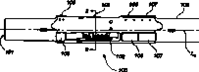
A figura 1 ilustra uma vista lateral de uma de muitas concretizações de um aparelho escareador expansível utilizando certos aspectos das presentes invenções.Figure 1 illustrates a side view of one of many embodiments of an expandable countersinking apparatus using certain aspects of the present inventions.
A figura 2 ilustra uma vista transversal em seção transversal do aparelho escareador expansível, conforme indicado pela linha em seção 2-2 na figura 1 e utilizando certos aspectos das presentes invenções.Figure 2 illustrates a cross-sectional view of the expandable countersinking device, as indicated by the line in section 2-2 in figure 1 and using certain aspects of the present inventions.
A figura 3 ilustra uma vista longitudinal em seção transversal doFigure 3 shows a longitudinal cross-sectional view of the
8/48 aparelho escareador expansível mostrado na figura 1 utilizando certos aspectos das presentes invenções.8/48 expandable countersink device shown in figure 1 using certain aspects of the present inventions.
A fiyuid 4 ilusííd uiiia vista íuiiyiíuuiiidi em seçau üaiisveisai ampliada de uma porção do aparelho escareador expansível mostrado na 5 figura 3 utilizando certos aspectos das presentes invenções.The fiyuid 4 illusid view seen in enlarged section from a portion of the expandable countersinking apparatus shown in Figure 3 using certain aspects of the present inventions.
A figura 5 ilustra uma vista ampliada em seção transversal de outra porção do aparelho escareador expansível mostrado na figura 3 utilizando certos aspectos das presentes invenções.Figure 5 illustrates an enlarged cross-sectional view of another portion of the expandable countersinking apparatus shown in Figure 3 using certain aspects of the present inventions.
A figura 6 ilustra uma vista ampliada em seção transversal de ΒΙΟ inda outra porção do aparelho escareador expansível mostrado na figura 3 utilizando certos aspectos das presentes invenções.Figure 6 illustrates an enlarged cross-sectional view of outra in yet another portion of the expandable reamer device shown in Figure 3 using certain aspects of the present inventions.
A figura 7 ilustra uma vista ampliada em seção transversal de uma porção adicional do aparelho escareador expansível mostrado na figura 3 utilizando certos aspectos das presentes invençõesFigure 7 illustrates an enlarged cross-sectional view of an additional portion of the expandable countersinking device shown in Figure 3 using certain aspects of the present inventions.
A figura 8 ilustra uma vista em seção transversal de uma montagem de cisalhamento de uma de muitas concretizações de um aparelho escareador expansível utilizando certos aspectos das presentes invenções.Figure 8 illustrates a cross-sectional view of a shear assembly of one of many embodiments of an expandable countersinking apparatus using certain aspects of the present inventions.
A figura 9 ilustra uma vista em seção transversal de uma montagem de bocal de uma de muitas concretizações de um aparelho escareador expansível utilizando certos aspectos das presentes invenções.Figure 9 illustrates a cross-sectional view of a nozzle assembly of one of many embodiments of an expandable countersinking apparatus using certain aspects of the present inventions.
A figura 10 ilustra uma vista de topo de uma lâmina de acordo com uma de muitas concretizações do escareador utilizando certos aspectos das presentes invenções.Figure 10 illustrates a top view of a blade according to one of many embodiments of the reamer using certain aspects of the present inventions.
A figura 11 ilustra uma vista longitudinal em seção transversal da lâmina tomada ao longo da linha de seção 11-11 na figura 10 utilizando certos aspectos das presentes invençõesFigure 11 illustrates a longitudinal cross-sectional view of the blade taken along section line 11-11 in Figure 10 using certain aspects of the present inventions.
A figura 12 ilustra uma vista de extremidade longitudinal da lâmina da figura 10 utilizando certos aspectos das presentes invenções.Figure 12 illustrates a longitudinal end view of the blade of Figure 10 using certain aspects of the present inventions.
A figura 13 ilustra uma vista em seção transversal tomada ao longo da linha de seção 13-13 na figura 11 utilizando certos aspectos das presentes invenções.Figure 13 illustrates a cross-sectional view taken along section line 13-13 in Figure 11 using certain aspects of the present inventions.
A figura 14 ilustra uma vista em seção transversal tomada aoFigure 14 illustrates a cross-sectional view taken at
9/48 longo da linha de seção 14-14 na figura 11 utilizando certos aspectos das presentes invenções.9/48 along section line 14-14 in figure 11 using certain aspects of the present inventions.
A figuro 15 ilustro uma visto cm scçqo transverso! dc uma luva de travamento de uma de muitas concretizações de um aparelho escareador 5 expansível utilizando certos aspectos das presentes invenções.Figure 15 is a cross-sectional view! a locking sleeve of one of many embodiments of an expandable countersinking apparatus 5 using certain aspects of the present inventions.
A figura 16 ilustra uma vista em perspectiva de uma culatra de uma de muitas concretizações de um aparelho escareador expansível utilizando certos aspectos das presentes invenções.Figure 16 illustrates a perspective view of a breech of one of many embodiments of an expandable countersinking apparatus using certain aspects of the present inventions.
A figura 17 ilustra uma ilustração longitudinal parcial em seção 10 transversal de uma de muitas concretizações de um aparelho escareador expansível em uma posição de ferramenta inicial fechada ou retraída e utilizando certos aspectos das presentes invenções.Figure 17 illustrates a partial longitudinal illustration in cross section 10 of one of many embodiments of an expandable countersinking device in an initial closed or retracted tool position and using certain aspects of the present inventions.
A figura 18 ilustra uma ilustração longitudinal parcial em seção transversal do aparelho escareador expansível da figura 17 na posição inicial da ferramenta, recebendo uma esfera em um percurso de fluido e utilizando certos aspectos das presentes invenções.Figure 18 illustrates a partial longitudinal cross-sectional illustration of the expandable countersinker of Figure 17 in the initial position of the tool, receiving a sphere in a fluid path and using certain aspects of the present inventions.
A figura 19 ilustra uma ilustração em seção transversal longitudinal parcial do aparelho escareador expansível da figura 17 na posição inicial da ferramenta na qual a esfera se move para um assento de esfera e é cap20 turada e utiliza certos aspectos das presentes invenções.Figure 19 illustrates a partial longitudinal cross-sectional illustration of the expandable countersinking apparatus of figure 17 in the initial position of the tool in which the ball moves to a ball seat and is capped and uses certain aspects of the present inventions.
A figura 20 ilustra uma ilustração longitudinal parcial em seção transversal do aparelho escareador expansível da figura 17 no qual uma montagem de cisalhamento é disparada na medida em que a pressão é acumulada e uma luva de percurso começa a se abaixar dentro do aparelho, deixando a posição de ferramenta inicial e utilizando certos aspectos das presentes invenções.Figure 20 illustrates a partial longitudinal cross-sectional illustration of the expandable countersinking device of Figure 17 in which a shear assembly is triggered as pressure is built up and a travel sleeve begins to lower inside the device, leaving the position initial tool and using certain aspects of the present inventions.
A figura 21 ilustra uma ilustração longitudinal parcial em seção transversal do aparelho escareador expansível da figura 17 no qual a luva de percurso se move para uma posição retida inferior enquanto uma lâmina que é pressionada por uma luva de empuxo sob a influência da pressão de fluido se move para uma posição estendida e utilizacertos aspectos das presentes invenções.Figure 21 illustrates a partial longitudinal cross-sectional illustration of the expandable countersinking device of Figure 17 in which the travel sleeve moves to a lower retained position while a blade that is pressed by a thrust sleeve under the influence of fluid pressure is moves to an extended position and uses certain aspects of the present inventions.
10/4810/48
A figura 22 ilustra uma ilustração longitudinal parcial em seção transversal do aparelho escareador expansível da figura 17 no qual as lâmi“ nas çuilia rtíprdSeiliada) sâu iuailíiuas na pusiçãu íuídliiieiile estendida pela luva de empuxo sob a influência da pressão de fluido e a luva de percurso se move para a posição retida e utiliza certos aspectos das presentes invenções.Figure 22 illustrates a partial longitudinal cross-sectional illustration of the expandable countersinking device of Figure 17 in which the laminae “in the ílilia rtíprdSeiliada) are uuailíiuas in the pusiuuation uuídliiieiile extended by the buoyancy sleeve under the influence of the fluid pressure and the travel sleeve if moves to the held position and uses certain aspects of the present inventions.
A figura 23 ilustra uma ilustração longitudinal parcial em seção transversal do aparelho escareador expansível da figura 17 no qual as lâminas (uma representada) são retraídas para uma posição retraída por uma mola de polarização, quando a pressão de fluido é dissipada e utiliza certos aspectos das presentes invenções.Figure 23 illustrates a partial longitudinal cross-sectional illustration of the expandable countersinking device of Figure 17 in which the blades (one shown) are retracted to a position retracted by a bias spring, when the fluid pressure is dissipated and uses certain aspects of the present inventions.
A figura 24 ilustra uma vista longitudinal parcial em seção transversal de uma de muitas concretizações de um aparelho escareador expansível incluindo um dispositivo de medição de dimensão de furo de sondagem e utilizando certos aspectos das presentes invenções.Figure 24 illustrates a partial longitudinal cross-sectional view of one of many embodiments of an expandable countersinking device including a borehole dimension measuring device and using certain aspects of the present inventions.
A figura 25 ilustra uma vista longitudinal em seção transversal de uma de muitas concretizações de um aparelho escareador expansível incorporando um elemento de limitação de movimento e utilizando certos aspectos das presentes invenções.Figure 25 illustrates a longitudinal cross-sectional view of one of many embodiments of an expandable countersinking device incorporating a movement limiting element and using certain aspects of the present inventions.
A figura 26 ilustra uma vista longitudinal em seção transversal de uma de muitas concretizações de um aparelho escareador expansível que incorpora outro elemento de limitação de movimento e utiliza certos aspectos das presentes invenções.Figure 26 illustrates a longitudinal cross-sectional view of one of the many embodiments of an expandable countersinking apparatus that incorporates another movement limiting element and utilizes certain aspects of the present inventions.
A figura 27 ilustra uma de muitas concretizações do aparelho escareador expansível apresentando elementos de rotação e utilizando certos aspectos das presentes invenções.Figure 27 illustrates one of many embodiments of the expandable countersinking apparatus having rotating elements and using certain aspects of the present inventions.
A figura 28 ilustra outra de muitas concretizações do aparelho escareador expansível apresentando elementos de rotação e utilizando certos aspectos das presentes invenções.Figure 28 illustrates another of many embodiments of the expandable countersinking apparatus having rotating elements and using certain aspects of the present inventions.
A figura 29 ilustra uma de muitas concretizações de um aparelho escareador expansível apresentando uma lâmina apresentando um elemento de rolete e utilizando certos aspectos das presentes invenções.Figure 29 illustrates one of many embodiments of an expandable countersinking apparatus having a blade having a roller element and using certain aspects of the present inventions.
11/4811/48
A figura 30 ilustra outra de muitas concretizações de um aparelho escareador expansível apresentando uma lâmina apresentando um elemento aé roiete anguiar e uiiiizaiidu ceiius áspecius uas pieseiiíes invt;iições.Fig. 30 illustrates another one of many embodiments of an expandable countersinking apparatus having a blade having an angled air element and a special feature.
A figura 31 ilustra outra de muitas concretizações do aparelho escareador expansível apresentando elementos de roiete e utilizando certos aspectos das presentes invenções.Fig. 31 illustrates another one of many embodiments of the expandable countersinking apparatus featuring rodent elements and using certain aspects of the present inventions.
DESCRIÇÃO DETALHADADETAILED DESCRIPTION
As figuras descritas acima e a descrição escrita das estruturas e 10 funções específicas abaixo não são apresentadas para limitar o escopo do que os requerentes inventaram ou o escopo das reivindicações anexas. Em vez disso, as figuras e a descrição escrita são providas para ensinar qualquer pessoa versada na técnica a criar e a fazer uso das invenções para as quais a proteção de patente é buscada. Aqueles versados na técnica irão apreciar que nem todas as características de uma concretização comercial das invenções são descritas ou mostradas para fins de clareza e entendimento. Aqueles versados na técnica irão também apreciar que o desenvolvimento de uma efetiva concretização comercial incorporando os aspectos das presentes invenções irá exigir inúmeras decisões específicas de imple20 mentação para atingir o objetivo final do inventor para a concretização comercial. Tais decisões específicas de implementação podem incluir, e provavelmente não são limitadas ao, cumprimento com restrições relacionadas ao sistema, relacionadas ao negócio, relacionadas ao governo e a outras restrições, que podem variar por implementação específica, localização e de tem25 pos em tempos. Enquanto os esforços de um inventor poderíam ser complexos e demorados em um sentido absoluto, tais esforços seriam, contudo, uma rotina assumida por aqueles versados nesta técnica apresentando o benefício desta descrição. Deve ser entendido que as invenções descritas e ensinadas aqui são suscetíveis a inúmeras e várias modificações e formas alternativas. Por fim, o uso de um termo singular, tal como, mas não limitado a, um, não se destina a limitar o número de itens. Também, o uso de termos relacionais, tais como, mas não limitado a, de topo, de fundo, esquerdo,The figures described above and the written description of the structures and 10 specific functions below are not presented to limit the scope of what the claimants invented or the scope of the attached claims. Instead, the figures and written description are provided to teach anyone skilled in the art to create and make use of the inventions for which patent protection is sought. Those skilled in the art will appreciate that not all features of a commercial embodiment of the inventions are described or shown for the sake of clarity and understanding. Those skilled in the art will also appreciate that the development of an effective commercial embodiment incorporating aspects of the present inventions will require numerous specific implementation decisions to achieve the inventor's ultimate goal for commercial realization. Such specific implementation decisions may include, and are probably not limited to, compliance with system-related, business-related, government-related and other restrictions, which may vary by specific implementation, location and time. While the efforts of an inventor could be complex and time-consuming in an absolute sense, such efforts would nevertheless be a routine taken on by those skilled in the art with the benefit of this description. It should be understood that the inventions described and taught here are susceptible to numerous and various modifications and alternative forms. Finally, the use of a singular term, such as, but not limited to, one, is not intended to limit the number of items. Also, the use of relational terms, such as, but not limited to, top, bottom, left,
12/48 direito, superior, inferior, descendente, ascendente, lateral, e similares são usados na descrição escrita para fins de clareza na referência especifica às íiyuias tí ilau se destinaiil a iiiiiiiai u escupu da invenção OU uâã reivindicações anexas. Os termos acoplar, acoplado, acoplamento, a5 coplador, e termos similares são usados amplamente aqui e podem incluir qualquer método ou dispositivo para prender, ligar, unir, fixar, conectar, unir, inserir no mesmo, formar sobre o mesmo e no mesmo, comunicar, ou de outro modo associar, por exemplo, mecanicamente, magneticamente, eletricamente, quimicamente, diretamente ou indiretamente com elementos in10 termediários, uma ou mais peças de elemento s entre si e podem adicionalmente incluir, sem limitação a, formação integral de um elemento funcional com outro em uma maneira uniforme. O acoplamento pode ocorrer em qualquer direção, inclusive rotacionalmente. Os termos escarear, escareamento, escareador, e termos similares são usados amplamente aqui e podem incluir, sem limitação, qualquer manipulação, contato ou comunicação com um furo de sondagem subterrâneo ou porção do mesmo, direta ou indiretamente, constante ou intermitentemente, intencional ou inintencionalmente, e podem, mas não precisam, incluir o alargamento de um furo de sondagem, a remoção de um furo de sondagem, a formação ou outros materiais, ou o contato com materiais no fundo do poço, o lastreamento a compressão, o pressionamento, a perfuração ou outros processos no fundo do poço, ou um ou mais dos acima, singularmente ou em combinação. O escareamento pode ocorrer em qualquer direção e, enquanto o escareamento pode incluir o alargamento de um poço, não há necessidade disso.12/48 right, upper, lower, descending, ascending, lateral, and the like are used in the written description for the sake of clarity in the specific reference to the laws of the invention OR the attached claims. The terms coupling, coupling, coupling, a5 coplator, and similar terms are used widely here and may include any method or device for attaching, bonding, joining, fixing, connecting, joining, inserting into, forming on and in the same, communicate, or otherwise associate, for example, mechanically, magnetically, electrically, chemically, directly or indirectly with intermediate elements, one or more pieces of element s together and may additionally include, without limitation, integral formation of an element functional with others in a uniform manner. Coupling can take place in any direction, including rotationally. The terms countersink, countersinks, countersinks, and similar terms are used widely here and may include, without limitation, any manipulation, contact or communication with an underground borehole or portion thereof, directly or indirectly, constantly or intermittently, intentionally or unintentionally , and may, but need not, include the widening of a borehole, the removal of a borehole, formation or other materials, or contact with materials at the bottom of the well, ballast compression, pressing, drilling or other downhole processes, or one or more of the above, singly or in combination. Countersinking can occur in any direction and, while countersinking may include widening a well, there is no need for it.
Os requerentes criaram um aparelho escareador expansível para escarear uma formação subterrânea, que pode incluir um corpo tubular e uma ou mais lâminas. Cada lâmina pode ser posicionalmente acoplada a um trilho inclinado do corpo tubular e o escareador pode incluir uma luva de empuxo e um fluxo de fluido de perfuração se estendendo através de um furo interno do corpo tubular para conduzir o fluido de perfuração através do mesmo. Cada uma ou mais lâminas podem, mas não precisam, incluir pelo menos um elemento de corte configurado para remover material de umaApplicants have created an expandable countersink device to bore an underground formation, which may include a tubular body and one or more blades. Each blade can be positionally coupled to an inclined rail of the tubular body and the reamer can include a thrust sleeve and a flow of drilling fluid extending through an internal hole in the tubular body to guide the drilling fluid through it. Each or more blades can, but need not, include at least one cutting element configured to remove material from a
13/48 formação subterrânea durante o escareamento. Alternativamente, cada lâmina pode ser lisa, contornada, pode carecer de elementos de corte, ou poue inuiuii eienieiiius uc luide. Os eléiiiciiíúi dé rüléte pOdciTi 30Γ CjUfilCjUCr tipo exigido por uma aplicação específica, tal como liso ou contornado, e podem, mas não precisam, incluir elementos de corte, insertos ou outros elementosacoplados aos mesmos. A luva de empuxo pode ser disposta no furo interno do corpo tubular e pode ser acoplada a uma ou mais das lâminas, de tal modo a efetuar o movimento axial do mesmo ao longo do trilho para uma posição estendida responsiva à exposição a uma força ou pressão, por exemplo, de perfuração ou outro fluido que pode estar no percurso de fluxo do furo interno. Outras concretizações do aparelho escareador expansível são também providas. As ilustrações apresentadas aqui não são, em alguns exemplos, vistas reais de qualquer ferramenta de escareador específica, elemento de corte, ou outra característica de uma ferramenta de escareador, mas são representações idealizadas que são empregadas para descreverem a presente invenção. Adicionalmente, elementos comuns entre figuras podem reter a mesma designação numérica.13/48 underground formation during countersinking. Alternatively, each blade may be smooth, contoured, may have no cutting elements, or a little cut in length. The type of elements required for a specific application, such as smooth or contoured, and may, but need not, include cutting elements, inserts or other elements coupled to them. The buoyancy sleeve can be arranged in the inner hole of the tubular body and can be coupled to one or more of the blades, in such a way as to make the axial movement of it along the rail to an extended position responsive to exposure to a force or pressure , for example, from drilling or other fluid that may be in the flow path of the inner hole. Other embodiments of the expandable countersinking apparatus are also provided. The illustrations presented here are not, in some examples, actual views of any specific reamer tool, cutting element, or other characteristic of a reamer tool, but are idealized representations that are employed to describe the present invention. Additionally, common elements between figures can retain the same numerical designation.
A figura 1 ilustra uma vista lateral de uma de muitas concretizações de uma aparelho escareador expansível 100 utilizando certos aspectos das presentes invenções. O aparelho escareador expansível 100 pode incluir um corpo tubular geralmente cilíndrico 108 apresentando um eixo longitudinal L.sub.8. O corpo tubular 108 do aparelho escareador expansível 100 pode ter uma extremidade inferior 190 e uma extremidade superior 191. Os termos inferior e superior, conforme usados aqui com referência às extremidades 190, 191, se referem a posições típicas das extremidades 190, 191 uma com relação à outra, quando o aparelho escareador expansível 100 estiver posicionado dentro de um poço. A extremidade inferior 190 do corpo tubular 108 do aparelho escareador expansível 100 pode incluir um conjunto de roscas (por exemplo, um elemento de pino macho roscado) para conectar a extremidade inferior 190 a outra seção de uma coluna de perfuração ou outro componente, tal como de uma montagem de fundo de poço (BHA), tal como, por exemplo, um colar ou colares de perfuração conduzindo uma bro14/48 ca de perfuração piloto para perfurar um poço. Similarmente, a extremidade superior 191 do corpo tubular 108 do aparelho escareador expansível 100 pooe inciuir um conjunto de losuas (μυι exemplei, um clcJincníü dc CSÍXQ ÍC mea roscado) para conectar a extremidade superior 191 a outra seção de 5 uma coluna de perfuração ou outro componente de uma montagem de fundo de poço (BHA).Figure 1 illustrates a side view of one of many embodiments of an expandable countersinking apparatus 100 using certain aspects of the present inventions. The expandable countersinking apparatus 100 may include a generally cylindrical tubular body 108 having a longitudinal axis L.sub.8. The tubular body 108 of the expandable countersinking apparatus 100 may have a lower end 190 and an upper end 191. The terms lower and upper, as used herein with reference to ends 190, 191, refer to typical positions of the ends 190, 191 one with relative to the other, when the expandable countersink device 100 is positioned inside a well. The lower end 190 of the tubular body 108 of the expandable countersinking apparatus 100 may include a set of threads (for example, a threaded male pin element) for connecting the lower end 190 to another section of a drill string or other component, such as of a well-bottom assembly (BHA), such as, for example, a drilling collar or collars leading a pilot drill bro14 / 48 ca to drill a well. Similarly, the upper end 191 of the tubular body 108 of the expandable countersinking device 100 may include a set of lozenges (μυι exampleplei, a threaded female clamp) to connect the upper end 191 to another section of a drill string or other component of a downhole assembly (BHA).
Três blocos ou lâminas de cortador deslizantes 101, 102, 103 (vide figura 2) são posicionalmente retidos em relação circunferencialmente espaçada no corpo tubular 108, conforme descrito adicionalmente abaixo, e podem ser providos em uma posição ao longo do aparelho escareador expansível 100 intermediário à primeira extremidade inferior 190 e à segunda extremidade superior 191. As lâminas 101, 102, 103 podem ser constituídas de aço, carbureto de tungstênio, um material composto de partículas-matriz (por exemplo, partículas duras dispersadas por todo um material de matriz de metal), ou outros materiais adequados, conforme conhecido na técnica. As lâminas 101, 102, 103 são retidas em uma posição inicial retraída dentro do corpo tubular 108 do aparelho escareador expansível 100, conforme ilustrado na figura 17, mas podem ser movidas responsivas à aplicação de pressão hidráulica para a posição estendida (mostrada na figura 22) e movi20 das para uma posição retraída (mostrada na figura 23), quando desejado, conforme será descrito aqui. O aparelho escareador expansível 100 pode ser, embora não seja, configurado de tal modo que as lâminas 101, 102, 103 engatem as paredes de uma formação subterrânea circundando um poço no __qual o aparelho 100 é disposto para remover o material de formação, quan25 do as lâminas 101, 102, 103 estiverem na posição estendida, mas não podem ser operáveis para assim engatar as paredes de uma formação subterrânea dentro de um poço, quando as lâminas 101, 102, 103 estiverem na posição retraída. Enquanto o aparelho escareador expansível 100 inclui três lâminas 101, 102, 103, é contemplado que uma, duas ou mais de três lâmi30 nas podem ser utilizadas vantajosamente. Além disso, enquanto as lâminas 101, 102, 103 são simetricamente posicionadas circunferencialmente de modo axial ao longo do corpo tubular 108, as lâminas podem também serThree sliding cutter blocks or blades 101, 102, 103 (see figure 2) are positionally retained in circumferentially spaced relation in the tubular body 108, as further described below, and can be provided in a position along the expandable countersinking device 100 intermediate to first lower end 190 and second upper end 191. Blades 101, 102, 103 can be made of steel, tungsten carbide, a material composed of matrix particles (for example, hard particles dispersed throughout a metal matrix material ), or other suitable materials, as known in the art. Blades 101, 102, 103 are retained in an initial stowed position within the tubular body 108 of the expandable countersinking apparatus 100, as shown in figure 17, but can be moved responsive to the application of hydraulic pressure to the extended position (shown in figure 22 ) and moved to a stowed position (shown in figure 23), when desired, as will be described here. The expandable countersinking apparatus 100 can, although not be, configured in such a way that the blades 101, 102, 103 engage the walls of an underground formation surrounding a well in which the apparatus 100 is arranged to remove the forming material when blades 101, 102, 103 are in the extended position, but cannot be operable to engage the walls of an underground formation within a well, when blades 101, 102, 103 are in the stowed position. While the expandable countersinking apparatus 100 includes three blades 101, 102, 103, it is contemplated that one, two or more than three blades 30 can be used advantageously. In addition, while the blades 101, 102, 103 are symmetrically positioned circumferentially axially along the tubular body 108, the blades can also be
15/48 posicionadas circunferencialmente de modo assimétrico, bem como assimetricamente ao longo do eixo longitudinal L.sub.8 na direção de cada extremidaoe iyue iy i. -----A figura 2 ilustra uma vista transversal em seção transversal do 5 aparelho escareador expansível 100, conforme indicado pela linha de seção 2-2 na figura 1 e utilizando certos aspectos da presente invenção. O corpo tubular 108 pode encerrar uma passagem de fluido 192 que se estende longitudinalmente através do corpo tubular 108. A passagem de fluido 192 pode direcionar o fluido substancialmente através de, por exemplo, um furo interno15/48 positioned circumferentially asymmetrically, as well as asymmetrically along the longitudinal axis L.sub.8 towards each end and iyue iy i. ----- Figure 2 illustrates a cross sectional view of the expandable countersinking apparatus 100, as indicated by section line 2-2 in figure 1 and using certain aspects of the present invention. The tubular body 108 can enclose a fluid passage 192 that extends longitudinally through the tubular body 108. The fluid passage 192 can direct the fluid substantially through, for example, an internal hole
151 de uma luva de percurso 128 desviando a relação para substancialmente proteger as lâminas 101, 102, 103 da exposição ao fluido de perfuração, particularmente na direção lateral, ou normal ao eixo longitudinal L.sub.8. Vantajosamente, o fluido aprisionado por particulados pode, menos provavelmente, causar a formação ou interferir com os aspectos operacionais do aparelho escareador expansível 100 por meio da proteção das lâminas 101, 102, 103 da exposição com o fluido. No entanto, é reconhecido que a proteção benéfica das lâminas 101, 102, 103 não é necessária para a operação do aparelho escareador expansível 100 onde, conforme explicado em maiores detalhes abaixo, a operação, isto é, a extensão da posição inicial, da po20 sição estendida e da posição retraída, ocorre por uma força axialmente direcionada que é o efeito livre da pressão de fluido e das forças de polarização de mola. Nesta concretização, que é uma de muitas, a força axialmente direcionada pode diretamente acionar as lâminas 101, 102, 103 pela influência __axial do meio de acionamento, tal como uma luva de empuxo 115 (mostrada na figura 3), por exemplo, e sem limitação, conforme melhor descrito aqui abaixo.151 of a travel sleeve 128 deviating the relationship to substantially protect the blades 101, 102, 103 from exposure to the drilling fluid, particularly in the lateral direction, or normal to the longitudinal axis L.sub.8. Advantageously, the fluid trapped by particulates may, less likely, cause formation or interfere with the operational aspects of the expandable countersinking apparatus 100 by protecting the blades 101, 102, 103 from exposure with the fluid. However, it is recognized that the beneficial protection of blades 101, 102, 103 is not necessary for the operation of the expandable countersinking device 100 where, as explained in more detail below, the operation, that is, the extension of the initial position, of the po20 extended position and retracted position, occurs by an axially directed force which is the free effect of fluid pressure and spring polarization forces. In this embodiment, which is one of many, the axially directed force can directly drive blades 101, 102, 103 by the __axial influence of the drive means, such as a thrust sleeve 115 (shown in figure 3), for example, and without limitation, as best described here below.
Com referência à figura 2, para melhor descrever aspectos da invenção, são mostradas lâminas 102 e 103 nas posições inicial ou retraída, enquanto a lâmina 101 é mostrada na posição para fora ou estendida. O a30 parelho escareador expansível 100 pode, mas não precisa, ser configurado de tal modo que a extensão radial ou lateral mais externa de cada das lâminas 101, 102, 103 seja rebaixada dentro do corpo tubular 108, quando naWith reference to figure 2, to better describe aspects of the invention, blades 102 and 103 are shown in the initial or retracted positions, while blade 101 is shown in the outward or extended position. The expandable reaming device a30 100 can, but need not, be configured in such a way that the outermost radial or lateral extension of each of the blades 101, 102, 103 is lowered into the tubular body 108, when in
16/48 posição inicial ou retraída, de modo a não poder se estender além da maior extensão do diâmetro externo do corpo tubular 108. Tal disposição pode proteger as laminas iüi, 102, 103 na nieuiud eiii que u aparelho escareador expansível 100 é disposto dentro de uma carcaça de um furo de sondagem, 5 e pode permitir que o aparelho escareador expansível 100 passe através de tal carcaça dentro de um furo de sondagem. Em outras concretizações, a extensão mais radial das lâminas 101, 101, 103 pode coincidir com o diâmetro externo do corpo tubular 108 ou ligeiramente se estender além do mesmo. Conforme ilustrado pela lâmina 101, as lâminas podem se estender a10 lém do diâmetro externo do corpo tubular 108, quando na posição estendida, para engatar as paredes de um furo de sondagem em uma operação de escareamento.16/48 initial or retracted position, so that it cannot extend beyond the largest extension of the outer diameter of the tubular body 108. Such an arrangement can protect the blades iüi, 102, 103 in the nieuiud eiii that an expandable countersinking device 100 is disposed inside of a borehole housing, 5 and may allow the expandable countersink apparatus 100 to pass through such a housing into a borehole. In other embodiments, the more radial extent of the blades 101, 101, 103 may coincide with the outer diameter of the tubular body 108 or slightly extend beyond it. As illustrated by blade 101, the blades can extend beyond 10 the outer diameter of the tubular body 108, when in the extended position, to engage the borehole walls in a countersinking operation.
A figura 3 ilustra uma vista longitudinal em seção transversal do aparelho escareador expansível mostrado nas figuras 1 e 2 tomada ao longo da linha de seção 3-3 mostrada na figura 2 e utilizando certos aspectos da presente invenção. Referência pode também ser feita às figuras 4-7, que mostram vistas longitudinais parciais ampliadas em seção transversal de várias porções do aparelho escareador expansível 100 mostrado na figura 3. Referência pode também ser feita novamente às figuras 1 e 2, conforme de20 sejado. O corpo tubular 108 posicionalmente retém respectivamente três blocos ou lâminas de cortador 101, 102, 103 nos três trilhos de lâmina 148. As lâminas 101, 102, 103 podem, cada qual, mas não precisam, conduzir uma pluralidade de elementos de corte 104 para engatar o material de uma formação subterrânea definindo a parede de um furo de sondagem aberto, quando as lâminas 101, 102, 103 estiverem em uma posição estendida (mostrada na figura 22). Os elementos de corte 104 podem ser cortadores compactos de diamante policristalino (PDC) ou outros elementos de corte conhecidos daquele versado na técnica e são descritos na Patente NorteAmericana No. 7.036.611, intitulada Aparelho escareador expansível para alargar furos de sondagem enquanto perfura e métodos de uso, a descrição total da qual é aqui incorporada para referência.Figure 3 illustrates a longitudinal cross-sectional view of the expandable countersinking apparatus shown in figures 1 and 2 taken along section line 3-3 shown in figure 2 and using certain aspects of the present invention. Reference can also be made to figures 4-7, which show partial longitudinal views enlarged in cross section of various portions of the expandable countersinking apparatus 100 shown in figure 3. Reference can also be made again to figures 1 and 2, as desired. The tubular body 108 positionally holds three blocks or cutter blades 101, 102, 103 respectively on the three blade tracks 148. Blades 101, 102, 103 can each, but need not, conduct a plurality of cutting elements 104 to engage the material of an underground formation defining the wall of an open borehole, when the blades 101, 102, 103 are in an extended position (shown in figure 22). The cutting elements 104 can be compact polycrystalline diamond cutters (PDC) or other cutting elements known to those skilled in the art and are described in U.S. Patent No. 7,036,611, entitled Expandable reamer for widening drillholes while drilling and methods of use, the full description of which is incorporated herein for reference.
O aparelho escareador expansível 100 pode incluir uma monta17/48 gem de cisalhamento 150 para reter o aparelho escareador expansível 100 na posição inicial com a fixação da luva de percurso 128 na direção da extremiaaae Superior lá i da rnesma. Reíeiôncia puue também &ci feita à figura 8, que mostra uma vista parcial da montagem de cisalhamento 150. A 5 montagem de cisalhamento 150 pode incluir uma luva de travamento 124, certo número de parafusos de cisalhamento 127 e a luva de percurso 128. A luva de travamento 124 pode ser retida dentro de um furo interno 151 do corpo tubular 108 entre uma abertura 152 e um anel de retenção 132 (mostrado na figura 7), e pode incluir uma vedação de anel em O 135 para impe10 dir que o fluido flua entre o furo externo 153 da luva de travamento 124 e o furo interno 151 do corpo tubular 108. A luva de travamento 124 pode incluir fendas de cisalhamento 154 para reter cada um dos parafusos de cisalhamento 127, onde, na concretização atual da invenção, cada parafuso de cisalhamento 127 pode ser roscado em um orifício de cisalhamento 155 da luva de percurso 128. Os parafusos de cisalhamento 127 podem reter a luva de percurso 128 dentro do furo interno 156 da luva de travamento 124 de tal modo a condicionalmente impedir que a luva de percurso 128 axialmente se mova em uma direção no fundo do poço 157, isto é, na direção da extremidade inferior 190 do aparelho escareador expansível 100. A luva de trava20 mento 124 pode incluir uma abertura interna 158 para impedir que a luva de percurso 128 se mova, por exemplo, na direção na parte de cima do poço 159, isto é, na direção da extremidade superior 191 do aparelho escareador expansível 100. Uma vedação de anel em O 134 veda a luva de percurso _128 entre o furo interno 156 da luva de travamento 124. Quando os parafu25 sos de cisalhamento 127 forem cisalhados, por exemplo, a luva de percursoThe expandable countersinking apparatus 100 may include a shearing mount 17/48 to hold the expandable countersinking apparatus 100 in the initial position with the fixing of the travel sleeve 128 towards the upper extremity and end of the branch. Also shown in Figure 8, which shows a partial view of the shear assembly 150. The shear assembly 150 may include a locking sleeve 124, a number of shear screws 127 and the travel sleeve 128. The sleeve locking means 124 can be retained inside an internal hole 151 of the tubular body 108 between an opening 152 and a retaining ring 132 (shown in figure 7), and can include an O-ring seal 135 to prevent the fluid from flowing between the outer hole 153 of the locking sleeve 124 and the inner hole 151 of the tubular body 108. The locking sleeve 124 can include shear slits 154 to retain each of the shear screws 127, where, in the current embodiment of the invention, each shear screw 127 can be threaded into a shear hole 155 of the travel sleeve 128. Shear screws 127 can retain the travel sleeve 128 within the inner hole 156 of the locking sleeve 124 in such a way that traditionally prevent the travel sleeve 128 axially from moving in one direction at the bottom of the pit 157, that is, towards the lower end 190 of the expandable countersinking device 100. the locking sleeve 124 may include an internal opening 158 to prevent the travel sleeve 128 moves, for example, towards the top of the well 159, that is, towards the upper end 191 of the expandable countersinking device 100. An O-ring seal 134 seals the travel sleeve _128 between the inner hole 156 of the locking sleeve 124. When the shear screws 127 are sheared, for example, the travel sleeve
128 poderá axialmente percorrer dentro do corpo tubular 108 na direção no fundo do poço 157. Vantajosamente, as porções dos parafusos de cisalhamento 127, quando cisalhadas, serão retidas dentro da luva de travamento 124 e da luva de percurso 128, de tal modo a impedir que as porções se sol30 tem ou fiquem alojadas em outros componentes, enquanto escareiam o furo de sondagem. Enquanto parafusos de cisalhamento 127 são mostrados, outros elementos de cisalhamento podem ser vantajosamente usados, por e18/48 xemplo, sem limitação, uma haste de cisalhamento, um fio de cisalhamento ou um pino de cisalhamento, singularmente ou em combinação. Opcionalmente, outros eiementos dê cisaiharfíOiιίυ pudem inuluii uma eshuíuia paia--1--— retenção positiva dentro de componentes constituintes depois de serem des5 carregados, de maneira similar aos parafusos de cisalhamento 127 da concretização atual da invenção.128 can axially travel within the tubular body 108 towards the bottom of the well 157. Advantageously, the portions of the shear bolts 127, when sheared, will be retained within the locking sleeve 124 and the travel sleeve 128, in such a way as to prevent that the portions are soluble or have housed in other components, while the borehole will be exposed. While shear bolts 127 are shown, other shear elements can be advantageously used, for example, without limitation, a shearing rod, a shearing wire or a shearing pin, singly or in combination. Optionally, other elements of cisaiharfiOiιίυ could inuluii a skid to positive - 1 --— positive retention within constituent components after being unloaded, similar to the shear screws 127 of the current embodiment of the invention.
Com referência à figura 6, a luva de travamento 124 pode adicionalmente incluir um engaste 160 que axialmente retém uma luva de vedação 136 entre o furo interno 151 do corpo tubular 108 e um furo externoWith reference to figure 6, the locking sleeve 124 can additionally include a crimp 160 that axially retains a sealing sleeve 136 between the inner hole 151 of the tubular body 108 and an outer hole
162 da luva de percurso 128. A luva de travamento 124 pode também incluir uma ou mais orelhas 163 e um ou mais orifícios 161 axialmente espaçados em torno da mesma. Quando a luva de percurso 128 posicionar uma distância axial suficiente na direção no fundo do poço 157, uma ou mais orelhas 163 poderão saltar radialmente para dentro de tal modo a travar o movimen15 to da luva de percurso 128 entre as orelhas 163 da luva de travamento 134 e entre um elemento de absorção de choque 125 montado sobre uma extremidade superior da lua de vedação 126. Também, na medida em que a luva de percurso 128 posiciona uma distância axial suficiente na direção no fundo do poço 157, um ou mais orifícios 161 da luva de travamento 124 podem ficar fluidamente expostos, o que pode permitir que o fluido se comunique com um orifício de admissão de bocal 164 a partir da passagem de fluido 192. O elemento de absorção de choque 125 da luva de vedação 126 pode prover retenção de mola da luva de percurso 128 com as orelhas da luva de travamento 124 e pode também mitigar o choque de impacto, tal como pode ser causado pela luva de percurso 128, quando seu movimento for interrompido pela luva de vedação 126.162 of the travel sleeve 128. The locking sleeve 124 may also include one or more ears 163 and one or more holes 161 axially spaced around it. When the travel sleeve 128 positions a sufficient axial distance in the direction at the bottom of the pit 157, one or more ears 163 may jump radially inward in such a way as to stop the movement of the travel sleeve 128 between the ears 163 of the locking sleeve 134 and between a shock absorbing element 125 mounted on an upper end of the sealing moon 126. Also, as long as the travel sleeve 128 positions a sufficient axial distance in the direction at the bottom of the shaft 157, one or more holes 161 of the locking sleeve 124 can be fluidly exposed, which can allow the fluid to communicate with a nozzle intake port 164 from the fluid passage 192. The shock absorbing element 125 of the sealing sleeve 126 can provide retention spring of the travel sleeve 128 with the ears of the locking sleeve 124 and can also mitigate the impact shock, as can be caused by the travel sleeve 128, when its movement is interrupted by the sealing sleeve 126.
O elemento de absorção de choque 125 pode compreender um material flexível ou maleável, tal como, por exemplo, um elastômero ou outro polímero. Em pelo menos uma concretização, por exemplo, o elemento de absorção de choque 125 pode compreender uma borracha de nitrilo. A utilização de um elemento de absorção de choque 125 entre a luva de percurso 128 e a luva de vedação 126 pode reduzir ou impedir a deformação peloThe shock absorbing element 125 may comprise a flexible or malleable material, such as, for example, an elastomer or other polymer. In at least one embodiment, for example, the shock absorbing element 125 may comprise a nitrile rubber. The use of a shock absorbing element 125 between the travel sleeve 128 and the sealing sleeve 126 can reduce or prevent deformation by
19/48 menos da luva de percurso 128 ou da luva de vedação 126 que pode, de outro modo, ocorrer devido ao impacto entre elas.19/48 less than the travel sleeve 128 or the sealing sleeve 126 which may otherwise occur due to the impact between them.
Deve sei iiuiadu que qudisqucí eteinentüi ue vedação ou clcmento s de absorção de choque descritos aqui que podem ser incluídos den5 tro do aparelho escareador expansível 100 podem compreender qualquer material adequado, como é conhecido na técnica, tal como, por exemplo, um polímero ou um elastômero. Opcionalmente, um material compreendendo um elemento de vedação pode ser selecionado para uso em temperatura relativamente alta (por exemplo, de cerca de 204,4 graus Celsius (400 grausYou should know that any shock absorbing seal or seal described herein that can be included within the expandable countersinking apparatus 100 may comprise any suitable material, as is known in the art, such as, for example, a polymer or a elastomer. Optionally, a material comprising a sealing element can be selected for use at a relatively high temperature (for example, about 204.4 degrees Celsius (400 degrees
Fahrenheit) ou mais). Por exemplo, as vedações podem ser compreendidas de Teflon™, material de polieteretercetona (PEEK ™), um material de polímero, ou um elastômero, ou pode compreender uma vedação de metal contra metal adequada para condições de furo de sondagem esperadas de acordo com uma aplicação específica. Especificamente, qualquer elemento de vedação ou elemento de absorção de choque descrito aqui, tais como o elemento de absorção de choque 125 e os elementos de vedação 134 eFahrenheit) or more). For example, the seals may be comprised of Teflon ™, polyetheretherketone material (PEEK ™), a polymer material, or an elastomer, or it may comprise a metal-to-metal seal suitable for expected borehole conditions according to an expected borehole condition. specific application. Specifically, any sealing element or shock absorbing element described here, such as shock absorbing element 125 and sealing elements 134 and
135, discutidos acima, ou elementos de vedação, tal como a vedação 136 discutida abaixo, ou outros elementos de vedação incluídos por um aparelho escareador expansível da invenção, podem compreender qualquer material configurado para uso em temperatura relativamente alta, ambientes de furo de sondagem altamente corrosivos, ou qualquer condição exigida por uma aplicação específica.135, discussed above, or sealing elements, such as the seal 136 discussed below, or other sealing elements included by an expandable reamer device of the invention, can comprise any material configured for use in relatively high temperature, highly borehole environments. corrosive, or any condition required by a specific application.
A luva de vedação 126 pode incluir um anel de vedação em OSealing sleeve 126 may include an O-ring
136, tal como para vedá-la entre o furo interno 151 do corpo tubular 108, e/ou uma vedação em T 137, tal como para vedá-la entre o furo externo 162 da luva de percurso 128, que pode, mas não precisa, completar a vedação do fluido entre a luva de percurso 128 e o orifício de admissão de bocal 164. Adicionalmente, a luva de vedação 126 pode axialmente alinhar, guiar e/ou suportar a luva de percurso 128 dentro do corpo tubular 108, singularmente ou em combinação. Além disso, as vedações da luva de vedação 136 e 137 podem também impedir que o fluido hidráulico vaze de dentro do aparelho escareador expansível 100 para fora do aparelho escareador expansível 100136, such as to seal it between the inner hole 151 of the tubular body 108, and / or a T-seal 137, as well as to seal it between the outer hole 162 of the travel sleeve 128, which can, but does not need , complete the fluid seal between the travel sleeve 128 and the nozzle inlet orifice 164. Additionally, the sealing sleeve 126 can axially align, guide and / or support the travel sleeve 128 within the tubular body 108, singularly or in combination. In addition, the seals of the sealing sleeve 136 and 137 can also prevent hydraulic fluid from leaking from inside the expandable countersinking apparatus 100 out of the expandable countersinking apparatus 100
20/48 por meio do orifício de admissão de bocal 164 antes de a luva de percurso 128 ser liberada de sua posição inicial, por exemplo.20/48 through the nozzle intake port 164 before the travel sleeve 128 is released from its initial position, for example.
uma exn ei i iiuaue nu íuuuu uu puçu 1G5 ua !uvd uc percurso 120 (vide também a figura 5), que pode incluir uma luva de batente de assento 5 130, pode ser alinhada, axialmente guiada e/ou sustentada por um pistão anular ou luva de destravamento 117. A luva de destravamento 117 (“lowlock sleeve”) pode ser axialmente acoplada a uma luva de empuxo 115 que pode ser cilindricamente retida entre a luva de percurso 128 e o furo internoan exn ei i iiuaue nu íuuuu uu puçu 1G5 ua! uvd uc course 120 (see also figure 5), which can include a seat stop sleeve 5 130, can be aligned, axially guided and / or supported by an annular piston or release sleeve 117. The release sleeve 117 (“lowlock sleeve”) can be axially coupled to a thrust sleeve 115 that can be cylindrically retained between the travel sleeve 128 and the inner hole
151 do corpo tubular 108. Quando a luva de percurso 128 estiver na posição pronta ou inicial durante a perfuração, a pressão hidráulica poderá atuar sobre a luva de empuxo 115, tal como concêntrica ao eixo de ferramenta e com a luva de destravamento 117 entre o furo externo 162 da luva de percurso 128 e o furo interno 151 do corpo tubular 108, por exemplo. Com ou sem pressão hidráulica, quando o aparelho escareador expansível 100 esti15 ver na posição inicial, a luva de empuxo 115 poderá ser impedida de se mover na direção na parte de cima do poço 159 por uma montagem de destravamento, tal como, por exemplo, um ou mais ganchos 166 da luva de destravamento 117.151 of the tubular body 108. When the travel sleeve 128 is in the ready or initial position during drilling, hydraulic pressure may act on the thrust sleeve 115, as well as concentric to the tool shaft and with the release sleeve 117 between the outer hole 162 of the travel sleeve 128 and inner hole 151 of the tubular body 108, for example. With or without hydraulic pressure, when the expandable countersink device 100 is in the initial position, the thrust sleeve 115 may be prevented from moving towards the top of the well 159 by an unlocking assembly, such as, for example, one or more hooks 166 of the unlocking sleeve 117.
Os ganchos 166 podem ser posicionalmente retidos entre uma ranhura anular 167 no furo interno 151 do corpo tubular 108 e a luva de batente de assento 130. Cada cão 166 da luva de destravamento 117 é um engaste ou engate de cão de travamento apresentando um detentor expansível 168 que poderá engatar a ranhura 167 do corpo tubular 108, quando compressivamente engatado pela luva de batente de assento 130. Os gan25 chos 166 retêm a luva de destravamento 117 no lugar e podem impedir que a luva de empuxo 115 se mova na direção na parte de cima do poço 159 até que a extremidade ou a luva de batente de assento 130, com seu diâmetro externo maior 169, percorra além da luva de destravamento 117, o que pode permitir que os ganchos 166 se retraiam axialmente para dentro na direção do diâmetro externo menor 170 da luva de percurso 128. Quando os ganchos 166 se retraírem axialmente para dentro, por exemplo, eles poderão ser desengatados da ranhura 167 do corpo tubular 108, o que pode permitirThe hooks 166 can be positionally retained between an annular groove 167 in the inner hole 151 of the tubular body 108 and the seat stop sleeve 130. Each dog 166 of the unlocking sleeve 117 is a crimp or locking dog hitch featuring an expandable stopper 168 which can engage the groove 167 of the tubular body 108 when compressively engaged by the seat stop sleeve 130. The hooks 166 hold the unlocking sleeve 117 in place and can prevent the thrust sleeve 115 from moving in the direction towards from the top of the well 159 until the end or seat stop sleeve 130, with its larger outer diameter 169, runs past the unlocking sleeve 117, which may allow hooks 166 to retract axially inward in the direction of the diameter smaller external 170 of the travel sleeve 128. When the hooks 166 retract axially inward, for example, they can be disengaged from the groove 167 of the tubular body 108, which may allow
21/48 que a luva de empuxo 115 seja submetida à pressão hidráulica principalmente na direção axial, tal como na direção na parte de cima do poço 159.21/48 that the thrust sleeve 115 is subjected to hydraulic pressure mainly in the axial direction, as well as in the direction at the top of the well 159.
A i nui itdyei11 de via<jiHláinento 150 pode exigir um ato afirmativo, tal como introduzindo uma esfera ou outro elemento de restrição no aparelho 5 escareador expansível 100, para fazer com que a pressão do fluxo de fluido hidráulico aumente, antes que os parafusos de cisalhamento 127 cisalhem.The track link 150 may require an affirmative act, such as introducing a sphere or other restraining element into the expandable countersink apparatus 5, to cause the pressure in the hydraulic fluid flow to increase, before the shear 127 shear.
A extremidade no fundo do poço 165 da luva de percurso 128 pode incluir dentro de seu furo interno uma luva de aprisionamento de esfera 129 que pode incluir um tampão 131. Uma vedação de anel em O 139 pode também prover uma vedação entre a luva de aprisionamento de esfera 129 e o tampão 131. Um elemento de restrição na forma de esfera 147, por exemplo, pode ser introduzido no aparelho escareador expansível 100 a fim de permitir a operação do aparelho escareador expansível 100 para iniciar ou disparar a ação da montagem de cisalhamento 150. Depois que a esfera 147 é introduzida, o fluido irá conduzir a esfera 147 para a luva de aprisionamento de esfera 129, o que pode permitir que a esfera 147 seja retida e vedada pela peça de assento do tampão 131 e pela luva de aprisionamento de esfera 129. Se ou quando a esfera 147 obstruir o fluxo de fluido que é aprisionado na luva de aprisionamento de esfera 129, o fluido ou a pressão hidráulica poderá se formar dentro do aparelho escareador expansível 100 até que, por exemplo, os parafusos de cisalhamento 127 cisalhem. Depois do cisalhamento dos parafusos de cisalhamento 127, a luva de percurso 128 juntamente com a luva de batente de assento coaxialmente retida 130 poderá axialmente percorrer, sob a influência da pressão hidráulica, por exemplo, na direção no fundo do poço 157 até que a luva de percurso 128 seja novamente axialmente retida pela luva de travamento 124, que, conforme descrito acima, se move para uma posição inferior. Depois disso, por exemplo, o fluxo de fluido pode ser restabelecido através dos orifícios de fluido 173 na luva de percurso 128 acima da esfera 147.The bottom end of the well 165 of the travel sleeve 128 may include inside its inner bore a ball locking sleeve 129 which can include a plug 131. An O-ring seal 139 can also provide a seal between the locking sleeve ball 129 and plug 131. A ball-shaped restraining element 147, for example, can be introduced into expandable countersinking apparatus 100 in order to allow operation of expandable countersinking apparatus 100 to initiate or trigger the action of the shear assembly 150. After ball 147 is introduced, the fluid will drive ball 147 into ball locking sleeve 129, which can allow ball 147 to be retained and sealed by the cap seat piece 131 and the locking sleeve ball 129. If or when ball 147 obstructs the flow of fluid that is trapped in ball 129 trapping sleeve, fluid or hydraulic pressure may form within the expanding countersink device 100 until, for example, shear bolts 127 shear. After shearing the shear bolts 127, the travel sleeve 128 together with the coaxially retained seat stop sleeve 130 may axially travel, under the influence of hydraulic pressure, for example, in the direction at the bottom of the well 157 until the sleeve path 128 is again axially retained by the locking sleeve 124, which, as described above, moves to a lower position. After that, for example, the fluid flow can be restored through the fluid orifices 173 in the travel sleeve 128 above the ball 147.
Opcionalmente, a esfera 147 usada para ativar o aparelho escareador expansível 100 pode engatar a luva de aprisionamento de esfera 129 e o tampão 131 que incluem características maleáveis, de tal modo que aOptionally, the ball 147 used to activate the expandable countersinking apparatus 100 can engage the ball locking sleeve 129 and the plug 131 which include malleable features, such that the
22/48 esfera 147 possa ser moldada nos mesmos na medida em que ela é assentada. Isto pode impedir que a esfera 147 se mova ao redor e potencialmente cause proDÍemas ou óctiiub du οροί cli iu esucireãdür expansível 100.22/48 sphere 147 can be molded into them as it is seated. This can prevent sphere 147 from moving around and potentially cause problems or expansion of οροί cli iu esucireãdür expandable 100.
Também, a fim de suportar a luva de percurso 128 e mitigar os 5 efeitos de vibração depois que a luva de percurso 128 é axialmente retida, por exemplo, a luva de batente de assento 130 e a extremidade no fundo do poço 165 da luva de percurso 128 podem ser retidas em uma luva estabilizadora 122. Pode ser feita também referência às figuras 5 e 22. A luva estabilizadora 122 pode ser acoplada ao furo interno 151 do corpo tubular 108 e retida entre um anel de retenção 133 e uma luva de proteção 121, que podem ser mantidos pela abertura anular 171 no furo interno 151 do corpo tubular 108. O anel de retenção 133 pode ser mantido dentro de uma ranhura anular 172 no furo interno 151 do corpo tubular 108. A luva de proteção 121 pode prover proteção da natureza erosiva do fluido hidráulico para o corpo tubular 108, por exemplo, permitindo que o fluido hidráulico flua através dos orifícios de fluido 173 da luva de percurso 128, atinja a luva de proteção 121 e passe a luva estabilizadora 122, quando a luva de percurso 128 for retida no mesmo.Also, in order to support the travel sleeve 128 and mitigate the 5 vibration effects after the travel sleeve 128 is axially retained, for example, the seat stop sleeve 130 and the end of the well 165 of the travel sleeve. path 128 can be retained in a stabilizer sleeve 122. Reference can also be made to figures 5 and 22. The stabilizer sleeve 122 can be attached to the inner hole 151 of the tubular body 108 and retained between a retaining ring 133 and a protective sleeve. 121, which can be maintained by the annular opening 171 in the inner hole 151 of the tubular body 108. The retaining ring 133 can be kept within an annular groove 172 in the inner hole 151 of the tubular body 108. The protective sleeve 121 can provide protection of the erosive nature of the hydraulic fluid to the tubular body 108, for example, allowing the hydraulic fluid to flow through the fluid holes 173 of the travel sleeve 128, reach the protective sleeve 121 and pass the stabilizer sleeve 122 when o the travel sleeve 128 is retained therein.
Depois que a luva de percurso 128 percorre o suficiente para permitir que os ganchos 166 da luva de destravamento 117 sejam desengatados da ranhura 167 do corpo tubular 108, por exemplo, os ganchos 166 da luva de destravamento 117, que podem ser conectados à luva de empuxo 115, podem se mover todos na direção na parte de cima do poço159. Refe__rência pode ser também feita às figuras 5, 6 e 21. A fim de que a luva de empuxo 115 se mova na direção na parte de cima do poço 159, a pressão diferencial entre o furo interno 151 e o lado externo 183 do corpo tubular 108 causada pelo fluxo de fluido hidráulico tem que ser suficiente para superar a força de restauração ou a polarização de uma mola 116, que pode ser qualquer força ou polarização exigida por uma aplicação específica. A mola de compressão 116 que pode resistir ao movimento da luva de empuxo 115 na direção na parte de cima do poço 159 pode ser retida na superfície externa 175 da luva de empuxo 115, por exemplo, entre um anel 113 conectado emAfter the travel sleeve 128 travels far enough to allow the hooks 166 of the release sleeve 117 to be disengaged from the groove 167 of the tubular body 108, for example, the hooks 166 of the release sleeve 117, which can be connected to the sleeve thrust 115, they can all move towards the top of the well159. Reference can also be made to figures 5, 6 and 21. In order for the buoyant sleeve 115 to move towards the top of the well 159, the differential pressure between the inner hole 151 and the outer side 183 of the tubular body 108 caused by the flow of hydraulic fluid must be sufficient to overcome the restoring force or polarization of a spring 116, which can be any force or polarization required by a specific application. The compression spring 116 which can resist the movement of the buoyant sleeve 115 in the direction at the top of the well 159 can be retained on the outer surface 175 of the buoyant sleeve 115, for example, between a ring 113 connected in
23/48 uma ranhura 174 do corpo tubular 108 e a luva de destravamento 117. A luva de empuxo 115 pode axialmente percorrer na direção na parte de cima se mover além da abertura superior do anel 113 e além da luva de proteção 5 184 na direção no fundo do poço 157. A luva de empuxo 115 pode incluir uma vedação, tal como a vedação em T 138, entre o corpo tubular 108, uma vedação, tal como a vedação T 137, entre a luva de percurso 128, e uma vedação, tal como a vedação axial 141, entre a luva de percurso 128 e a luva de empuxo 115.23/48 a groove 174 of the tubular body 108 and the release sleeve 117. The thrust sleeve 115 can axially travel in the direction at the top to move beyond the upper opening of the ring 113 and beyond the protective sleeve 5 184 in the direction at the bottom of the well 157. Thrust sleeve 115 may include a seal, such as the T 138 seal, between the tubular body 108, a seal, such as the T 137 seal, between the travel sleeve 128, and a seal , such as the axial seal 141, between the travel sleeve 128 and the thrust sleeve 115.
A luva de empuxo 115 pode incluir em sua seção na parte de cima do poço 176 uma culatra 114 acoplada à mesma, conforme mostrada na figura 6, por exemplo. A culatra 114 (também mostrada na figura 16) pode incluir três braços 177, cada um dos quais pode ser acoplado a uma das lâminas 101, 102, 103, por exemplo, por uma articulação provida de pinoThe buoyant sleeve 115 may include in its section at the top of the well 176 a yoke 114 coupled to it, as shown in figure 6, for example. The yoke 114 (also shown in figure 16) can include three arms 177, each of which can be coupled to one of the blades 101, 102, 103, for example, by a hinge provided with a pin
178. Cada braço 177 pode incluir uma superfície formada adequada para expelir detritos, por exemplo, na medida em que as lâminas 101, 102, 103 são retraídas na direção da posição retraída. A superfície formada dos braços 177, em conjunção com a parede adjacente da cavidade do corpo 108, pode prover ângulos incluídos de aproximadamente 20 graus, o que pode ser preferível para desalojar ou remover qualquer xisto amontoado, e pode adicionalmente incluir material de superfície de baixo atrito, de tal modo a impedir a adesão pelos cortes de formação ou outros detritos. A articulação provida de pino 178 pode incluir uma articulação 118 que acopla uma lâmina ao braço 177, onde a articulação 118 pode ser acoplada à lâmina por um pino, tal como um pino de lâmina 119, e presa por um anel de retenção 142, e a articulação 118 pode ser acoplada ao braço 177 por um pino de culatra 120, que é preso por um contrapino 144, por exemplo. A articulação provida de pino 178 pode permitir que as lâminas 101, 102, 103 transitem rotacionalmente em torno dos braços 177 da culatra 114, particularmente na medi30 da em que o meio de acionamento transita diretamente as lâminas 101, 102, 103 entre as posições estendida e retraídas. Vantajosamente, o meio de acionamento, isto é, a luva de empuxo 115, a culatra 114, e/ou a articulação178. Each arm 177 may include a formed surface suitable for expelling debris, for example, as blades 101, 102, 103 are retracted in the direction of the retracted position. The formed surface of the arms 177, in conjunction with the adjacent body cavity wall 108, may provide included angles of approximately 20 degrees, which may be preferable to dislodge or remove any heaped shale, and may additionally include surface material from below friction in such a way as to prevent adherence by formation cuts or other debris. The pin-provided hinge 178 can include a hinge 118 that attaches a blade to arm 177, where hinge 118 can be attached to the blade by a pin, such as a blade pin 119, and secured by a retaining ring 142, and the hinge 118 can be coupled to the arm 177 by a breech pin 120, which is secured by a cotter pin 144, for example. The hinge provided with pin 178 may allow the blades 101, 102, 103 to rotate rotationally around the arms 177 of the breech 114, particularly as the drive means directly transports the blades 101, 102, 103 between the extended positions and retracted. Advantageously, the actuating means, that is, the thrust sleeve 115, the yoke 114, and / or the articulation
24/4824/48
178, pode diretamente retrair, bem como estender as lâminas 101, 102, 103, ao passo que o conhecimento convencional direcionou o uso de uma parte para captar a pressão hidráulica para forçar a lâmina Iatoraímento para fora e outra parte, tal como uma mola, para forçar as lâminas para dentro.178, can directly retract, as well as extend the blades 101, 102, 103, whereas conventional knowledge has directed the use of one part to capture hydraulic pressure to force the blade out and another part, such as a spring, to force the blades inward.
A fim de que as lâminas 101, 102, 103 possam transitar entre as posições estendida e retraída, elas podem ser, cada qual, posicionalmente acopladas a um dos trilhos de lâmina 148 no corpo tubular 108, conforme particularmente mostrado nas figuras 3 e 6. A lâmina 101 pode ser também mostrada nas figuras 10-14. O trilho de lâmina 148 pode incluir uma ranhura na forma de rabo de andorinha 179 que pode axialmente se estender ao longo do corpo tubular 108, tal como em uma inclinação oblíqua 180 apresentando um ângulo agudo com relação ao eixo longidutinal L8. Cada um das lâminas 101, 102, 103 pode incluir um anteparo na forma de rabo de andorinha 181 que substancialmente se casa com a ranhura na forma de rabo de andorinha 179 do trilho de lâmina 148, a fim de deslizavelmente prender as lâminas 101, 102, 103-ao corpo tubular 108. Quando a luva de empuxo 115 for influenciada pela pressão hidráulica, por exemplo, as lâminas 101, 102, 103 poderão se estender para cima e para fora através de um orifício de passagem de lâmina 182 para a posição estendida, tal como ficando prontas para escarear a parede do poço ou formação. As lâminasIn order that the blades 101, 102, 103 can transit between the extended and retracted positions, they can each be positionally coupled to one of the blade rails 148 in the tubular body 108, as particularly shown in figures 3 and 6. Blade 101 can also be shown in figures 10-14. The blade track 148 may include a dovetail groove 179 which can axially extend along the tubular body 108, such as at an oblique slope 180 having an acute angle to the longidutinal axis L 8 . Each of blades 101, 102, 103 may include a dovetail shield 181 that substantially matches the dovetail groove 179 of blade rail 148 in order to slide slides 101, 102 slidably , 103-to tubular body 108. When thrust sleeve 115 is influenced by hydraulic pressure, for example, blades 101, 102, 103 may extend upward and outward through a blade through hole 182 to the position extended, such as getting ready to countersink the wall of the well or formation. The blades
101, 102, 103 podem ser empurradas ao longo dos trilhos de lâmina 148 até que, por exemplo, o movimento para frente seja detido, tal como pelo corpo tubular 108 ou o bloco estabilizador superior 105 que é acoplado ao corpo tubular 108. Na posição para cima-para fora ou totalmente estendida, as lâminas 101, 102, 103 podem, mas não precisam, ser posicionadas de tal como que os elementos de corte 104 alarguem um furo de sondagem na formação subterrânea em uma quantidade prescrita, que pode ser qualquer quantidade, incluindo nenhuma. Quando a pressão hidráulica provida, por exemplo, pelo fluxo de fluido de perfuração através do aparelho escareador expansível 100 for liberada, a mola 116 poderá pressionar as lâminas 101,101, 102, 103 can be pushed along the blade rails 148 until, for example, the forward movement is stopped, such as by the tubular body 108 or the upper stabilizer block 105 which is coupled to the tubular body 108. In position up-out or fully extended, blades 101, 102, 103 can, but need not, be positioned such that the cutting elements 104 widen a borehole in the underground formation in a prescribed amount, which can be any quantity, including none. When the hydraulic pressure provided, for example, by the flow of drilling fluid through the expandable countersinking device 100 is released, the spring 116 can press the blades 101,
102, 103 através da luva de empuxo 1115 e da articulação provida de pino 178 para a posição retraída. Caso a montagem não seja prontamente retraí25/48 da através da força de mola, quando a ferramenta for puxada ascendentemente para cima para uma sapata de carcaça, por exemplo, a sapata poderá entrai em contato com as lâminas 101, 102, 103, o quo poder pressioná-las ou forçá-las para baixo nos trilhos 148, de tal modo a permitir que o aparelho escareador expansível 100 seja recolhido do furo de sondagem. Sob este aspecto, o aparelho escareador expansível 100 pode incluir uma característica de garantia de retração para adicionalmente auxiliar na remoção do aparelho escareador expansível de um furo de sondagem. A inclinação 180 dos trilhos de lâmina 148 pode ser de qualquer valor, mas é mostrada nesta concretização exemplificativa da invenção como sendo de cerca de 10 graus, tomada com relação ao eixo longitudinal L8 do aparelho escareador expansível 100. Enquanto a inclinação 180 dos trilhos de lâmina 148 é mostrada como sendo de cerca de dez graus, ela pode variar de uma extensão maior a uma extensão menor do que aquela ilustrada. Contudo, a inclinação 180 não deve ser menor do que substancialmente 35 graus, por razões discutidas baixo, para obter o benefício total deste aspecto da invenção. As lâminas 101, 102, 103, que são travadas nos trilhos de lâmina 148 com os anteparos na forma de rabo de andorinha 181 na medida em que elas são adicionalmente acionadas para a posição estendida podem permitir tolerâncias mais amplas, conforme comparadas aos escareadores hidráulicos convencionais, que podem exigir tolerâncias restritas entre os pistões de lâmina e o corpo tubular para radialmente acionar os pistões de lâmina para sua posição estendida. Consequentemente, as lâminas 101, 102, 103, podem ser mais robustas e apresentar menos probabilidade de ligar ou falhar devido ao bloqueio do fluido. Nesta concretização exemplificativa da invenção, as lâminas 101, 102, 103 podem ter uma ampla folga nas ranhuras 179 dos trilhos de lâmina 148, tal como uma folga de 1,5875 mm (1/16 polegadas), mais ou menos, entre o anteparo na forma de rabo de andorinha 181 e a ranhura na forma de rabo de andorinha 179. Deve ser reconhecido que o termo rabo de andorinha, quando da referência à ranhura 179 ou ao anteparo 181, não é limitativo, mas é direcionado amplamente na direção das estruturas nas quais cada lâmina 101, 102, 103 pode ser retida com o corpo102, 103 through thrust sleeve 1115 and the joint provided with pin 178 for the stowed position. If the assembly is not readily retracted by the spring force, when the tool is pulled upwards onto a casing shoe, for example, the shoe may come into contact with blades 101, 102, 103, the quo being able to press or force them downwards on the rails 148, in such a way as to allow the expandable countersinking apparatus 100 to be retracted from the borehole. In this regard, the expandable countersinking apparatus 100 may include a retraction guarantee feature to further assist in removing the expandable countersinking apparatus from a borehole. The slope 180 of the blade rails 148 can be of any value, but is shown in this exemplary embodiment of the invention to be about 10 degrees, taken with respect to the longitudinal axis L 8 of the expandable countersinking device 100. While the slope 180 of the rails of blade 148 is shown to be about ten degrees, it can vary from a greater extent to a lesser extent than that illustrated. However, the slope 180 should not be less than substantially 35 degrees, for reasons discussed below, to obtain the full benefit of this aspect of the invention. Blades 101, 102, 103, which are locked on blade rails 148 with dovetail bulkheads 181 as they are additionally driven to the extended position can allow for wider tolerances as compared to conventional hydraulic countersinks , which may require strict tolerances between the blade pistons and the tubular body to radially drive the blade pistons to their extended position. Consequently, blades 101, 102, 103, may be more robust and less likely to start or fail due to fluid blockage. In this exemplary embodiment of the invention, blades 101, 102, 103 can have a wide gap in the grooves 179 of the blade rails 148, such as a gap of 1.5875 mm (1/16 inch), more or less, between the bulkhead in the form of swallowtail 181 and the groove in the form of swallowtail 179. It should be recognized that the term swallowtail, when referring to groove 179 or bulkhead 181, is not limiting, but is directed largely towards structures in which each blade 101, 102, 103 can be retained with the body
26/4826/48
108 do aparelho escareador expansível 100, enquanto permite adicionalmente que as lâminas 101, 102, 103 transitem entre duas ou mais posições 1 - - »x..:u, - --i- ia —: 4 sn---- x_____x~ iyu uuo uiiiiuo uc ιαιιιιιια—nu ouiii uuwci J k z iuà ^üXX^TT^CTV^i108 of the expandable countersink device 100, while additionally allowing blades 101, 102, 103 to pass between two or more positions 1 - - »x ..: u, - --i-ia -: 4 sn ---- x _____ x ~ iyu uuo uiiiiuo uc ιαιιιιιια — nu ouiii uuwci J kz iuà ^ üXX ^ TT ^ CTV ^ i
Vantajosamente, as forças reativas naturais que podem atuar sobre os cortadores 104 nas lâminas 101, 102, 103 durante a rotação do aparelho escareador expansível 100 no engate de uma formação enquanto do escarear de furo de sondagem podem ajudar a adicionalmente empurrar as lâminas 101, 102, 103 na direção para fora estendida, retendo-as com esta força em sua posição totalmente para fora ou estendida. Forças de perfuração que atuam sobre os cortadores 104, portanto, juntamente com uma maior pressão dentro do aparelho escareador expansível 100 criando um diferencial de pressão com aquele do furo de sondagem externo à ferramenta, podem ajudar a adicionalmente reter as lâminas 101, 102, 103 na posição estendida ou para fora. Também, na medida em que o aparelho escareador expansível 100 está escareando ou perfurando, a pressão de fluido deverá ser reduzida, quando a combinação da inclinação 180 dos trilhos de lâmina 148 for, por exemplo, suficientemente rasa, permitindo que forças reativas que atuam sobre os cortadores 104 ou as lâminas 101, 102, 103 desloquem o efeito de polarização da mola de polarização 116. Sob este aspecto, a aplicação da pressão de fluido hidráulico pode ser substancialmente minimizada, enquanto perfura, já que uma vantagem mecânica pode permitir que forças reativas que atuam sobre os cortadores 104, quando acoplados com a inclinação oblíqua substancialmente mais rasa 180 dos trilhos 148, provejam a força de reação exigida para reter as lâminas 101, 102, 103 em suas posições estendidas. Escareadores convencionais, que podem ter lâminas se estendendo substancialmente lateralmente para fora a partir de uma extensão de 35 graus ou maior (referenciada com relação ao eixo longitudinal), pode exigir a aplicação total, e continuada, da pressão hidráulica para manter as lâminas em uma posição estendida. Consequentemente e diferentemente do caso com os escareadores expansíveis convencionais, as lâminas 101, 102, 103 do aparelho escareador expansível 100 podem tender a se abrir, conforme em oposição à tendência de se fecharem, quando escareiamAdvantageously, the natural reactive forces that can act on the cutters 104 on the blades 101, 102, 103 during the rotation of the expandable countersinking device 100 when engaging a formation while drilling the borehole can further help to push the blades 101, 102 , 103 in the extended outward direction, retaining them with this force in their fully outward or extended position. Drilling forces acting on the cutters 104, therefore, together with a higher pressure inside the expandable countersinking device 100 creating a pressure differential with that of the borehole external to the tool, can additionally help to retain the blades 101, 102, 103 in the extended or out position. Also, as the expandable countersink device 100 is countersinking or drilling, the fluid pressure should be reduced when the combination of the 180 slope of the blade rails 148 is, for example, sufficiently shallow, allowing reactive forces acting on cutters 104 or blades 101, 102, 103 displace the polarization effect of bias spring 116. In this regard, the application of hydraulic fluid pressure can be substantially minimized, while drilling, as a mechanical advantage can allow forces Reactives acting on cutters 104, when coupled with the substantially shallower slant 180 of rails 148, provide the reaction force required to hold blades 101, 102, 103 in their extended positions. Conventional reamers, which may have blades extending substantially laterally outward from an extension of 35 degrees or greater (referenced to the longitudinal axis), may require full, continued application of hydraulic pressure to keep the blades in one extended position. Consequently and unlike the case with conventional expandable countersinks, the blades 101, 102, 103 of the expandable countersink device 100 may tend to open, as opposed to the tendency to close, when they will be scarred.
27/48 um furo de sondagem. A direção da força de corte livre e, portanto, da força reativa pode ser ajustada com a alteração da inclinação traseira, exposição e inclinação lateral doo oortadoroc 104, por oxomplo, que podem ou não estar presentes, para melhor atingir uma força livre que tende a mover as lâminas27/48 a borehole. The direction of the free cutting force and, therefore, of the reactive force can be adjusted by changing the rear tilt, exposure and lateral tilt of the oortadoroc 104, for example, which may or may not be present, to better achieve a free tending force moving the blades
101, 102, 103 para sua extensão para fora mais completa. Um efeito similar pode também ser conseguido sem o uso de cortadores 104, tal como, por exemplo, em outras concretizações descritas aqui.101, 102, 103 for its most complete outward extension. A similar effect can also be achieved without the use of cutters 104, as, for example, in other embodiments described here.
Outra vantagem de um trilho raso assim denominado, isto é, a inclinação substancialmente pequena 180 apresentando um ângulo agudo, pode ser, por exemplo, uma maior eficiência de retração de força de mola. A eficiência de retração aperfeiçoada permite que taxas de mola aperfeiçoadas ou customizadas sejam utilizadas para controlar a extensão da força de polarização pela mola 116, tal como selecionando a força de polarização exigida para ser superada pela pressão hidráulica para começar a mover ou estender por completo as lâminas 101, 102, 103. Também, com eficiência de retração aperfeiçoada, uma maior garantia da retração de lâmina poderá ser obtida, por exemplo, quando a pressão de fluido hidráulico for eliminada do aparelho escareador expansível 100. Opcionalmente, a mola pode ser précarregada quando o aparelho escareador expansível 100 estiver na posição inicial ou retraída, o que pode permitir que uma quantidade mínima de força de retração seja constantemente aplicada.Another advantage of a so-called shallow rail, that is, the substantially small slope 180 having an acute angle, can be, for example, a greater efficiency of spring force retraction. The improved retraction efficiency allows improved or customized spring rates to be used to control the extent of the bias force by spring 116, such as selecting the required bias force to be overcome by hydraulic pressure to start moving or fully extending the biases. blades 101, 102, 103. Also, with improved retraction efficiency, a greater guarantee of blade retraction can be obtained, for example, when the hydraulic fluid pressure is eliminated from the expandable countersink device 100. Optionally, the spring can be preloaded when the expandable countersink apparatus 100 is in the initial or retracted position, which may allow a minimum amount of retraction force to be constantly applied.
Outra vantagem provida pelos trilhos de lâmina 148 pode ser o desenho único de cada ranhura na forma de rabo de andorinha 179, sendo provida uma ranhura 179 para receber um dos anteparos na forma de rabo de andorinha opostos 181 das guias 187 em cada lado das lâminas 101,Another advantage provided by the blade rails 148 may be the unique design of each groove in the form of dovetail 179, a groove 179 being provided to receive one of the dovetail bulkheads opposite 181 of the guides 187 on each side of the blades 101,
102, 103. Nos escareadores expansíveis convencionais, cada lado de uma lâmina móvel pode incluir uma pluralidade de aletas ou canais a serem recebidos nos canais opostos ou aletas do corpo de escareador, respectivamente, onde tais disposições podem ser altamente propensas à aderência, quando, por exemplo, as lâminas forem submetidas às forças operacionais e pressões. Além da facilidade de extensão e retração de lâmina sem aderência ao longo do trilho 148 ou no mesmo, o desenho único de anteparo e ra28/48 nhura cooperante pode prover suporte estrutural de não aderência para operação de lâmina, particularmente quando engata uma formação enquanto escareia por exemplo102, 103. In conventional expandable countersinks, each side of a movable blade may include a plurality of fins or channels to be received in the opposite channels or fins of the countersink body, respectively, where such arrangements can be highly prone to adhesion, when, for example, the blades are subjected to operational forces and pressures. In addition to the ease of extending and retracting the blade without adherence along the track 148 or on it, the unique design of the bulkhead and ra28 / 48 cooperating groove can provide structural non-adherence support for blade operation, particularly when engaging a formation while scoring for example
Além do bloco estabilizador superior 105, o aparelho escareador 5 expansível 100 pode incluir um bloco estabilizador intermediário 106 e um bloco estabilizador inferior 107. Opcionalmente, o bloco estabilizador intermediário 106 e o bioco estabilizador inferior 107 podem ser combinados em um bloco estabilizador unitário. Os blocos estabilizadores 105, 106, 107 ajudam a centralizar o aparelho escareador expansível 100 no furo de perfura10 ção enquanto do percurso para a posição através de uma carcaça ou de uma coluna de revestimento interior ou, outro exemplo, enquanto da perfuração e escareamento do furo de sondagem. Conforme mencionado acima, o bloco estabilizador superior 105 pode ser usado para deter ou limitar o movimento dianteiro das lâminas 101, 102, 103, o que pode determinar a ex15 tensão na qual as lâminas 101, 102, 103 podem engatar um furo de sondagem enquanto da perfuração. O bloco estabilizador superior 105, além de prover um batente traseiro para limitar a extensão lateral das lâminas, pode prover a estabilidade adicional quando, por exemplo, as lâminas 101, 102, 103 forem retraídas e o aparelho escareador expansível 100 de uma coluna de perfuração for posicionado dentro de um furo de sondagem em uma área onde um furo de sondagem expandido não é desejado enquanto a coluna de perfuração estiver girando.In addition to the upper stabilizing block 105, the expandable countersinking apparatus 100 may include an intermediate stabilizing block 106 and a lower stabilizing block 107. Optionally, the intermediate stabilizing block 106 and the lower stabilizing block 107 can be combined into a unitary stabilizing block. The stabilizer blocks 105, 106, 107 help to center the expandable countersinking device 100 in the drilling hole10 while traveling to position through a housing or an inner lining column or, for example, while drilling and countersinking the hole polling. As mentioned above, the upper stabilizer block 105 can be used to stop or limit the forward movement of the blades 101, 102, 103, which can determine the extent to which the blades 101, 102, 103 can engage a borehole while drilling. The upper stabilizer block 105, in addition to providing a rear stop to limit the lateral extension of the blades, can provide additional stability when, for example, blades 101, 102, 103 are retracted and the expandable countersink device 100 of a drill string is positioned inside a borehole in an area where an expanded borehole is not desired while the drill string is rotating.
Vantajosamente, o bloco estabilizador superior 105 pode ser montado, removido e/ou substituído por um técnico, particularmente no campo, o que pode permitir que a extensão na qual as lâminas 101, 102, 103 engatam o furo de sondagem seja prontamente aumentada ou diminuída em uma extensão diferente daquela ilustrada. Opcionalmente, é reconhecido que um batente associado em um lado do trilho do bloco 105 pode ser adaptado a fim de controlar a extensão na qual as lâminas 101, 102, 103 podem se estender lateralmente, quando totalmente posicionadas na posição estendida ao longo dos trilhos de lâmina 148. Os blocos estabilizadores 105, 106, 107 podem incluir calços de mancai de face dura (não mostrados),Advantageously, the upper stabilizer block 105 can be mounted, removed and / or replaced by a technician, particularly in the field, which can allow the extent to which blades 101, 102, 103 engage the borehole to be readily enlarged or decreased to a different extent than illustrated. Optionally, it is recognized that an associated stop on one side of the block 105 rail can be adapted to control the extent to which the blades 101, 102, 103 can extend laterally, when fully positioned in the extended position along the rail tracks. blade 148. Stabilizer blocks 105, 106, 107 may include hard-faced bearing blocks (not shown),
29/48 por exemplo, para prover uma superfície para entrar em contato com uma parede de um furo de sondagem enquanto estabiliza o aparelho na mesma29/48 for example, to provide a surface to come into contact with a borehole wall while stabilizing the device in the same
4ι i rmnrsmrtn rKM-fi ir/->4ι i rmnrsmrtn rKM-fi ir / ->
□ üiuiitU Liiiiti UpVruyciU uU pUii vii viyuV.□ üiuiitU Liiiiti UpVruyciU uU pUii vii viyuV.
Também, o aparelho escareador expansível 100 pode incluir bo5 cais de carbureto de tungstênio 110, conforme mostrado na figura 9. Os bocais 110 são providos para resfriar e limpar os elementos de corte 104, por exemplo, ou para eliminar os detritos das lâminas 101, 102, 103 durante a perfuração. Os bocais 110 podem incluir uma vedação, tal como uma vedação de anel em O 140, entre cada bocal 110 e o corpo tubular 108 para pro10 ver uma vedação entre os dois componentes. Conforme mostrado, os bocais 110 são configurados para direcionar o fluido de perfuração para as lâminas 101, 102, 103 na direção no fundo do poço 157, mas podem ser configurados para direcionar o fluido lateralmente, na direção na parte de cima do poço 159, ou em qualquer direção exigida por uma aplicação específica.Also, the expandable countersinking apparatus 100 may include a tungsten carbide pier 5, as shown in figure 9. The nozzles 110 are provided to cool and clean the cutting elements 104, for example, or to eliminate debris from the blades 101, 102, 103 during drilling. The nozzles 110 can include a seal, such as an O-ring seal 140, between each nozzle 110 and the tubular body 108 to provide a seal between the two components. As shown, nozzles 110 are configured to direct drilling fluid to blades 101, 102, 103 in the direction at the bottom of the well 157, but can be configured to direct the fluid laterally, towards the top of the well 159, or in any direction required by a specific application.
O aparelho escareador expansível, ou escareador, 100 é agora descrito em termos de seus aspectos operacionais. Referência pode ser feita às figuras 17-23, em particular, e opcionalmente às figuras 1-16, conforme desejável. O aparelho escareador expansível 100 pode ser instalado em uma montagem de fundo de poço acima de uma broca piloto e, se incluído, acima ou abaixo do dispositivo de medição enquanto da perfuração (MWD) e incorporado em um sistema dirigível giratório (RSS) e sistema de loop fechado giratório (RCLS), por exemplo. Antes do disparo do aparelho escareador expansível 100, o aparelho escareador expansível 100 pode ser mantido em uma posição retraída inicial, conforme mostrado na figura 17. Por exemplo, a luva de percurso 128 dentro do aparelho escareador expansível 100 pode isolar o percurso de fluxo de fluido e impedir a extensão inadvertida das lâminas 101, 102, 103, conforme anteriormente descrito, e pode ser retida pela montagem de cisalhamento 150, tal como com os parafusos de cisalhamento 127 presos na luva de travamento 124, que pode ser conecta30 da ao corpo tubular 108. Enquanto a luva de percurso 128 é mantida na posição inicial, o meio de acionamento de lâmina pode ser impedido de diretamente acionar as lâminas 101, 102, 103, acionadas por forças de polariza30/48 ção ou por forças hidráulicas. A luva de percurso 128 pode ter, em sua extremidade inferior, uma peça de extremidade ampliada, tal como uma luva üe batente de assente 130. Esta luva de batente dc sssento dc diâmetro maior 130 pode reter os ganchos 166 da luva de destravamento 117 em uma 5 posição fixa, o que pode impedir que a luva de empuxo 115 se mova para cima sob os efeitos de pressão diferencial e acione as lâminas 101, 102,The expandable countersink device, or countersink, 100 is now described in terms of its operational aspects. Reference can be made to figures 17-23, in particular, and optionally to figures 1-16, as desired. The expandable countersink device 100 can be installed in a downhole assembly above a pilot drill and, if included, above or below the measurement device while drilling (MWD) and incorporated in a rotary steerable system (RSS) and system rotating closed loop (RCLS), for example. Before firing the expandable countersink device 100, the expandable countersink device 100 can be held in an initial retracted position, as shown in figure 17. For example, the travel sleeve 128 inside the expandable countersink device 100 can isolate the flow path of fluid and prevent inadvertent extension of the blades 101, 102, 103, as previously described, and can be retained by the shear assembly 150, such as with the shear screws 127 attached to the locking sleeve 124, which can be connected to the body tubular 108. As long as the travel sleeve 128 is kept in the starting position, the blade drive means can be prevented from directly driving the blades 101, 102, 103, driven by polarizing forces 30/48 or hydraulic forces. The travel glove 128 may have, at its lower end, an enlarged end piece, such as a seat stop glove 130. This larger diameter seat stop glove 130 can hold the hooks 166 of the release glove 117 in a fixed position, which can prevent thrust sleeve 115 from moving upwards under the effects of differential pressure and drive blades 101, 102,
103. Os ganchos de engate 166 podem travar o detentor de engate ou expansível 168 em uma ranhura 167 no furo interno 151 do corpo tubular 108. Quando for desejado disparar o aparelho escareador expansível 100, o fluxo de fluido de perfuração poderá ser momentaneamente cessado, caso exigido, e uma esfera 147, ou outro elemento de restrição de fluido, pode ser deixada cair na coluna de perfuração e resumido o bombeamento do fluido de perfuração. A esfera 147 pode se mover na direção no fundo do poço 157 sob a influência da gravidade e/ou do fluxo do fluido de perfuração, conforme mostrado na figura 18. Depois de um curto tempo, por exemplo, a esfera 147 pode alcançar um assento de esfera da luva de aprisionamento de esfera 129, conforme mostrado na figura 19. A esfera 147 pode deter o fluxo de fluido de perfuração, o que pode fazer com que a pressão seja formada acima dela na coluna de perfuração. Na medida em que a pressão é formada, a esfera pode ser adicionalmente assentada no tampão 131 ou contra o mesmo, o que pode ser feito de um material resiliente, tal como tetratuoroetileno (TFE), ou revestido com o mesmo.103. Hitch hooks 166 can lock the hitch or expandable holder 168 into a groove 167 in the inner hole 151 of the tubular body 108. When it is desired to fire the expandable countersinking device 100, the flow of drilling fluid may be momentarily stopped, if required, and a ball 147, or other fluid restraining element, can be dropped on the drill string and pumped the drill fluid resumed. Ball 147 can move towards the bottom of well 157 under the influence of gravity and / or the flow of the drilling fluid, as shown in figure 18. After a short time, for example, ball 147 can reach a seat of ball locking sleeve 129, as shown in figure 19. Ball 147 can stop the flow of drilling fluid, which can cause pressure to form above it in the drill string. As the pressure is formed, the ball can be additionally seated in the cap 131 or against it, which can be made of a resilient material, such as tetratuoroethylene (TFE), or coated with it.
Com referência à figura 20, em um nível de pressão predeterminado, que pode ser ajustado com base, por exemplo, no número e nas resis25 tências de cisalhamento individuais dos parafusos de cisalhamento 127 (formados de latão ou outro material adequado) instalados inicialmente no aparelho escareador expansível 100, os parafusos de cisalhamento 127 podem falhar na montagem de cisalhamento 150, o que pode permitir que a luva de percurso 128 fique sem vedação e se mova para baixo. Na medida em que a luva de percurso 128 com a extremidade maior da luva de batente de assento 130 se move para baixo, os ganchos de engate 166 da luva de destravamento 117 podem ficar livres para se moverem para dentro na dire31/48With reference to figure 20, at a predetermined pressure level, which can be adjusted based, for example, on the number and individual shear strengths of the shear screws 127 (formed of brass or other suitable material) initially installed in the apparatus expandable countersink 100, the shear bolts 127 may fail in the shear assembly 150, which may allow the travel sleeve 128 to be unsealed and move downward. As the travel sleeve 128 with the long end of the seat stop sleeve 130 moves downwards, the engagement hooks 166 of the unlocking sleeve 117 can be free to move inward in the direction31 / 48
32/48 para baixo, ela poderá ser detida com o desvio do fluxo ou os orifícios de fluido 173 localizados acima da esfera 147 na luva de percurso 128 saindo32/48 downwards, it can be stopped with the flow deviation or the fluid orifices 173 located above the ball 147 in the travel sleeve 128 coming out
Ο X/~|L lt οχλΙτϊζϊΑλ<Jiirz>Ί Ο Ί>->Ο X / ~ | L lt οχλΙτϊζϊΑλ <Jiirz> Ί Ο Ί>->
vwi muC« vUL· 11 ι ινχΙ I l<-4 1^1 CrCI IU VU XJ V.vwi muC «vUL · 11 ι ινχΙ I l <-4 1 ^ 1 CrCI IU VU XJ V.
4W VI IUUL· UUIU-1 1 I , M UUU MM de ajudar a impedir ou a minimizar os danos da erosão do fluxo de fluido de perfuração que incide sobre a mesma. O fluxo de fluido de perfuração pode então continuar até a montagem de fundo de poço, e a extremidade superior da luva de percurso 128 pode ficar aprisionada, isto é, travada, entre as orelhas 163 da luva de travamento 124 e o elemento de absorção de choque 125 da luva de vedação 126 e a extremidade inferior da luva de percurso 128 pode ser lateralmente estabilizada pela luva estabilizadora 122.4W VI IUUL · UUIU-1 1 I, M UUU MM to help prevent or minimize damage from erosion of the drilling fluid flow that falls on it. The flow of drilling fluid can then continue until the downhole assembly, and the upper end of the travel sleeve 128 can be trapped, that is, locked, between the ears 163 of the locking sleeve 124 and the absorbing element. shock 125 of the sealing sleeve 126 and the lower end of the travel sleeve 128 can be laterally stabilized by the stabilizer sleeve 122.
Quando a pressão de fluido de perfuração for liberada, a mola 116 poderá ajudar a acionar a luva de destravamento 117 e a luva de empuxo 115 com as lâminas conectadas 101, 102, 103 de volta para baixo e para dentro substancialmente para sua posição original ou inicial para a posição retraída, vide figura 23. Contudo, uma vez que a luva de percurso 128 tenha se movido para uma posição travada descendente, a luva de batente de assento de diâmetro maior 130 não pode mais reter os ganchos 166 fora e na ranhura 167, sendo assim a luva de engate ou destravamento 117 desengatada e submetida a diferenciais de pressão para operação ou ativação subsequente.When the drilling fluid pressure is released, spring 116 can assist in driving release sleeve 117 and thrust sleeve 115 with connected blades 101, 102, 103 back down and in substantially to their original position or starting to the stowed position, see figure 23. However, once the travel sleeve 128 has moved to a locked down position, the larger diameter seat stop sleeve 130 can no longer retain the hooks 166 outside and in the groove 167, with the coupling or unlocking sleeve 117 disengaged and subjected to pressure differentials for subsequent operation or activation.
Toda vez que o fluxo de fluido de perfuração é restabelecido no tubo de perfuração e através do aparelho escareador expansível 100, a luva de empuxo 115 com a culatra 114 e as lâminas 101, 102, 103 podem se mover para cima com as lâminas 101, 102, 103 seguindo as rampas ou trilhosWhenever the flow of drilling fluid is re-established in the drill pipe and through the expandable countersinking device 100, the thrust sleeve 115 with yoke 114 and blades 101, 102, 103 can move upward with blades 101, 102, 103 following ramps or rails
148 para novamente cortar ou escarear o diâmetro prescrito em um furo de sondagem. Toda vez que o fluxo de fluido de perfuração é interrompido, isto é, a pressão diferencial caia abaixo da força de restauração da mola 116, as lâminas 101, 102, 103 podem ser retraídas, tal como descrito acima, através da mola 116148 to again cut or countersink the prescribed diameter in a borehole. Whenever the flow of drilling fluid is interrupted, that is, the differential pressure falls below the restoring force of spring 116, blades 101, 102, 103 can be retracted, as described above, through spring 116
Em aspectos da invenção, o aparelho escareador expansívelIn aspects of the invention, the expandable countersink device
100 pode superar desvantagens dos escareadores convencionais. Por exemplo, um escareador hidráulico convencional pode ter utilizado pressão de100 can overcome disadvantages of conventional countersinks. For example, a conventional hydraulic countersink may have used
33/48 dentro da ferramenta para aplicar força contra os pistões do cortador que se moveram radiaimente para fora. É sentido por alguns que a natureza do esmroorlnr porp-iitiij rii fnrçoc Hopolir>hoHç>g inrlinoceQi-n o yrri perrassem os pistões, impedindo que as molas os retraíssem. Com a provi5 são do aparelho escareador expansível 100 que desliza cada das lâminas para cima em uma rampa angulada relativamente rasa, forças de perfuração maiores podem ser usadas para abrir e estender as lâminas para uma posição máxima enquanto da transferência das forças através do batente de calço de face dura superior sem quaisquer danos ao mesmo e subsequente10 mente permitindo que a mola retraia as lâminas depois disso sem emperramento ou inclinação.33/48 inside the tool to apply force against the cutter pistons that moved radially outward. It is felt by some that the nature of the punching porp-iitiij rii fnrçoc Hopolir> hoHç> g inrlinoceQi-n o yrri would lose the pistons, preventing the springs from retracting them. With the provision of the expandable countersinking device 100 which slides each blade upwards on a relatively shallow angled ramp, greater drilling forces can be used to open and extend the blades to a maximum position while transferring forces through the wedge stop. upper hard face without any damage to it and subsequently10 allowing the spring to retract the blades thereafter without jamming or tilting.
O aparelho escareador expansível 100 pode incluir lâminas que, caso não sejam retraídas pela mola, podem ser empurradas para baixo na rampa do trilho por meio do contato com a parede de furo de sondagem, por exemplo, ou a carcaça , o que pode permitir que o aparelho escareador expansível 100 seja puxado através da carcaça , provendo um tipo de função à prova de falhas. O aparelho escareador expansível 100 pode ou não ser vedado em torno das lâminas, mas não exige vedações no mesmo, tais como as vedações de alto custo ou adaptadas usadas em alguns escareadores expansíveis convencionais.The expandable countersink device 100 may include blades which, if not retracted by the spring, can be pushed down the rail ramp through contact with the borehole wall, for example, or the housing, which may allow the expandable countersink device 100 is pulled through the housing, providing a type of fail-safe function. The expandable countersink device 100 may or may not be sealed around the blades, but does not require seals on it, such as the high cost or adapted seals used in some conventional expandable countersinks.
O aparelho escareador expansível 100 pode incluir vãos livres que variam de ‘aproximadamente 0,254 mm (0,010 de uma polegada) a 0,0762 mm (0,0030 de uma polegada), por exemplo, entre partes adjacentes apresentando vedações dinâmicas entre as mesmas. As vedações dinâmi25 cas podem ser todas vedações circulares convencionais, ou podem ser vedações adaptadas, ou qualquer tipo de vedação exigido por uma aplicação específica. Além disso, o mecanismo de deslizamento ou o meio de acionamento, que pode incluir as lâminas nos trilhos, pode incluir vãos livres que variam de cerca de 1,27 mm (0,050 de uma polegada) a cerca de 0,254 mm (0,0100 de uma polegada), particularmente em torno de porções de rabo de andorinha, por exemplo. Vãos livres no aparelho escareador expansível, nas lâminas e nos trilhos podem variar até um ponto um tanto maior ou menor doThe expandable countersink apparatus 100 may include free spans ranging from ‘approximately 0.254 mm (0.010 of an inch) to 0.0762 mm (0.0030 of an inch), for example, between adjacent parts having dynamic seals between them. Dynamic seals can all be conventional circular seals, or they can be adapted seals, or any type of seal required by a specific application. In addition, the sliding mechanism or drive means, which may include the blades on the rails, may include free spans ranging from about 1.27 mm (0.050 of an inch) to about 0.254 mm (0.0100 of an inch), particularly around portions of swallowtail, for example. Free spans in the expandable countersink device, blades and rails can vary up to a point somewhat greater or less than
34/48 que indicado aqui. Os vãos livres e tolerâncias maiores das partes do aparelho escareador expansível 100 podem promover a faciiidade de operação, rnHii-yido rl onr^rAnpin miipono r\f\r particulados no fluido de perfuração e detritos de formação cortados da parede do furo de sondagem, por exemplo.34/48 that indicated here. The free spans and greater tolerances of the parts of the expandable countersinking apparatus 100 can promote the ease of operation, rnHii-yido rl onr ^ rAnpin miipono r \ f \ r particulate in the drilling fluid and formation debris cut from the borehole wall, for example.
Aspectos adicionais do aparelho escareador expansível 100 são agora providos:Additional aspects of the expandable countersink device 100 are now provided:
A lâmina 101 pode ser mantida no lugar ao longo do trilho 148 (mostrado na figura 2) por guias 187. A lâmina 101 pode incluir guias correspondentes 187, conforme mostrado nas figuras 10-14, por exemplo. Cada guia 187 pode ser compreendida de um único anteparo 108 opostamente localizado em cada lado do bloco 101 e pode incluir um ângulo teta que pode ser selecionado para impedir a aderência com as guias correspondentes do trilho 148 ou para outra finalidade exigida por uma aplicação específica. O ângulo teta incluído dos anteparos 181 da lâmina 101 nesta concretização pode ser de cerca de 30 graus, por exemplo, de tal modo que a lâmina 101 possa ser propensa a se mover para longe do trilho 148 no corpo 108 ou prover vão livre em torno do mesmo, quando, por exemplo, submetida à pressão hidráulica.The blade 101 can be held in place along the rail 148 (shown in figure 2) by guides 187. The blade 101 can include corresponding guides 187, as shown in figures 10-14, for example. Each guide 187 can be comprised of a single bulkhead 108 oppositely located on each side of the block 101 and can include a theta angle that can be selected to prevent adherence with the corresponding guides of the rail 148 or for another purpose required by a specific application. The included theta angle of the bulkheads 181 of the blade 101 in this embodiment can be about 30 degrees, for example, such that the blade 101 can be prone to move away from the rail 148 in the body 108 or provide a free span around when, for example, subjected to hydraulic pressure.
As lâminas 101, 102, 103 podem ser conectadas por uma culatra 114 com a montagem de articulação, conforme descrito aqui, o que pode permitir que as lâminas 101, 102, 103 se movam para cima e radialmente para fora ao longo da rampa de 10 graus, nesta concretização da invenção, na medida em que o meio de acionamento, isto é, a culatra 114 e a luva de empuxo 115, se move axialmente pra cima. O elo da montagem de articulação pode, mas não precisa ser provido de pino tanto nos blocos como na culatra em uma maneira similar. A montagem de articulação, além de permitir que o meio de acionamento diretamente estenda e retraia as lâminas 101, 102, 103 substancialmente na direção longitudinal ou axial, pode permitir que a extensão para cima e radialmente para fora das lâminas 101, 102, 103 com a rotação através de um ângulo, que pode ser qualquer ângulo, aproximadamente de 48 graus nesta concretização da invenção, durante o acío35/48 namento direto do meio de acionamento e das lâminas 101, 102, 103.Blades 101, 102, 103 can be connected by a breech 114 with the hinge assembly, as described here, which can allow blades 101, 102, 103 to move upward and radially outward along the 10 ramp degrees, in this embodiment of the invention, insofar as the actuation means, i.e., the yoke 114 and the thrust sleeve 115, move axially upwards. The link of the hinge assembly can, but does not need to be provided with a pin either in the blocks or in the breech in a similar manner. The hinge assembly, in addition to allowing the drive medium to directly extend and retract the blades 101, 102, 103 substantially in the longitudinal or axial direction, can allow the extension upward and radially outward of the blades 101, 102, 103 with rotation through an angle, which can be any angle, approximately 48 degrees in this embodiment of the invention, during direct action 35/48 of the drive means and blades 101, 102, 103.
No caso de as lâminas 101, 102, 103 de algum modo não seIn the event that blades 101, 102, 103 somehow do not
-moverem para trás prontamcntc no rompa doo trilhoc do lâmina 148 sob a força de polarização da mola de retração 116, então, o aparelho escareador expansível 100 é puxado do furo de sondagem, o contato com a parede do furo de sondagem podendo bater as lâminas 101, 102, 103 na inclinação 180 dos trilhos 148. Caso necessário, as lâminas 101, 102, 103 do aparelho escareador expansível 100 podem ser puxadas contra a carcaça , que pode empurrar as lâminas 101, 102, 103 101, 102, 103 adicionalmente de volta para a posição retraída, o que pode permitir o acesso e a remoção do aparelho escareador expansível 100 através da carcaça . Em outras concretizações da invenção, a luva de percurso pode ser vedada para impedir que o fluxo de fluido saia da ferramenta através dos orifícios de passagem de lâmina 192, e, depois do disparo, a vedação possa ser mantida.-move back at the break of the blade 148 under the polarization force of the retraction spring 116, then the expandable countersinking device 100 is pulled from the borehole, the contact with the borehole wall can hit the blades 101, 102, 103 at the 180 inclination of the rails 148. If necessary, the blades 101, 102, 103 of the expandable countersinking device 100 can be pulled against the housing, which can push the blades 101, 102, 103 101, 102, 103 additionally back to the stowed position, which can allow access and removal of the expandable countersinking device 100 through the housing. In other embodiments of the invention, the travel sleeve can be sealed to prevent fluid flow out of the tool through the blade through holes 192, and, after firing, the seal can be maintained.
Os bocais 110, conforme mencionado acima, podem ser dirigidos na direção de fluxo através do aparelho escareador expansível 100 a partir de dentro do corpo tubular 108 para baixo e pra fora radialmente para a coroa anular entre o corpo tubular 108 e um furo de sondagem. O direcionamento dos bocais 110 em tal direção descendente pode causar o contra20 fluxo na medida em que o fluxo sai do bocal e se mistura com o contrafluxo móvel anular que retorna para o furo de sondagem e pode aperfeiçoar a limpeza e a remoção de cortes. Os bocais 110 podem ser dirigidos nos cortadores das lâminas 101, 102, 103 para limpeza máxima, e podem ser direcionalmente otimizados usando análise de dinâmica de fluido computacional (CFD).The nozzles 110, as mentioned above, can be directed in the flow direction through the expandable countersinking apparatus 100 from inside the tubular body 108 downwards and out radially to the annular crown between the tubular body 108 and a borehole. Directing the nozzles 110 in such a downward direction can cause the counter flow as the flow exits the nozzle and mixes with the annular mobile counter flow that returns to the borehole and can improve cleaning and removal of cuts. Nozzles 110 can be driven on blade cutters 101, 102, 103 for maximum cleaning, and can be directionally optimized using computational fluid dynamics (CFD) analysis.
O aparelho escareador expansível 100 pode incluir um conector roscado de proteção 109, tal como aquele mostrado na figura 4, que pode ser conectado à conexão de caixa inferior do corpo do escareador 108. Com a possibilidade de o corpo 108 ser um desenho de peça única, o conector roscado de proteção 109 permite que a conexão entre os dois seja mais resistente (apresente um maior torque de composição) do que uma ferramenta de duas peças convencional apresentando uma conexão superior e inferior.The expandable countersink device 100 can include a protective threaded connector 109, such as the one shown in figure 4, which can be connected to the lower housing connection of countersink body 108. With the possibility of body 108 being a one-piece design , the protective threaded connector 109 allows the connection between the two to be more resistant (with a higher compounding torque) than a conventional two-piece tool with an upper and lower connection.
36/4836/48
37/48 formações duras. As lâminas 101, 102, 103 podem incluir qualquer dos elementos acima, singularmente ou em combinação, conforme exigido por uma37/48 hard formations. Blades 101, 102, 103 can include any of the above elements, either singly or in combination, as required by a
-aplicação copcoífioa.—------------—-cooperative application .—------------—
A figura 24 mostra uma vista em seção transversal de uma con5 cretização de um aparelho escareador expansível 10 apresentando um dispositivo de medição 20 de acordo com outra concretização da invenção. O dispositivo de medição 20 pode prover uma indicação da distância entre o aparelho escareador expansível 10 e uma parede de um furo de sondagem que é perfurada, o que pode permitir que seja feita uma determinação quan10 to à extensão na qual o aparelho escareador expansível 10 pode alargar um furo de sondagem. Conforme mostrado, o dispositivo de medição 20 pode ser montado no corpo tubular 108 geralmente em uma direção perpendicular ao eixo longitudinal L8 do aparelho escareador expansível 10. O dispositivo de medição 20 pode ser acoplado a uma linha de comunicação 30 que se estende através de um corpo tubular 108 do aparelho escareador expansível 10 que pode incluir uma conexão de extremidade 40 na extremidade superior 191 do aparelho escareador expansível 10. A conexão de extremidade 40 pode ser configurada para compatibilidade de conexão com equipamento específico ou especializado, tal como uma submontagem de comunicaçãoFigure 24 shows a cross-sectional view of a rendering of an expandable countersinking device 10 showing a measuring device 20 according to another embodiment of the invention. The measuring device 20 can provide an indication of the distance between the expandable reamer 10 and a borehole wall that is drilled, which can allow a determination to be made as to the extent to which the expandable reamer 10 can widen a borehole. As shown, the measuring device 20 can be mounted on the tubular body 108 generally in a direction perpendicular to the longitudinal axis L 8 of the expandable countersinking device 10. The measuring device 20 can be coupled to a communication line 30 which extends through a tubular body 108 of the expandable reamer 10 that can include an end connection 40 to the upper end 191 of the expandable reamer 10. End connection 40 can be configured for connection compatibility with specific or specialized equipment, such as a subassembly of Communication
MWD. A linha de comunicação 30 pode também ser usada para suprir potência ao dispositivo de medição 20. O dispositivo de medição 20 pode ser configurado para detectar, analisar e/ou determinar o tamanho do furo de sondagem, ou pode ser usado simplesmente para detectar em qual o tamanho de um furo de sondagem pode ser analisado ou determinado por outro equipamento, como é entendido por aquele versado na técnica MWD, provendo assim uma determinação substancialmente precisa de um tamanho de furo de sondagem. O dispositivo de medição 20 poderá se tornar instrumental na determinação, quando o aparelho escareador expansível 10 não estiver perfurando em seu diâmetro pretendido, permitindo que medidas re30 mediais sejam tomadas do que perfurar por durações prolongadas ou milhares de metros para escarear um furo de sondagem que pode então ter que ser novamente escareado.MWD. The communication line 30 can also be used to supply power to the measuring device 20. The measuring device 20 can be configured to detect, analyze and / or determine the size of the borehole, or it can be used simply to detect at which the size of a borehole can be analyzed or determined by other equipment, as understood by one skilled in the MWD technique, thus providing a substantially accurate determination of a borehole size. The measuring device 20 may become instrumental in determining when the expandable countersinking device 10 is not drilling in its intended diameter, allowing re-medial measurements to be taken than drilling for prolonged durations or thousands of meters to bore a borehole that it may then have to be countersunk again.
38/4838/48
O dispositivo de medição 20 pode ser parte de um sistema de medição de base nuclear, tai como descrito na Patente U.S. No. 5.175.429, jjuiu iujiii <-/ uuiiuu, vi uuuvi lyuu uu i^uui v» iuiuii i ii^i nu ii iuvji pui uum i4V|Ui pru referência, e é cedida ao cessionário da invenção aqui descrita. O dispositivo de medição 20 pode também incluir calibres sônicos, sensores de proximidade, ou outros sensores adequados para determinar uma distância entre uma parede de um furo de sondagem e o aparelho escareador expansível 10. Opcionalmente, o dispositivo de medição 20 pode ser configurado, montado e usado para determinar a posição das lâminas móveis e/ou calços de apoio do aparelho escareador expansível 20, onde o diâmetro de furo de sondagem mínimo escareado pode ser deduzido de tais medições. Similarmente, um dispositivo de medição pode ser posicionado dentro da lâmina móvel de modo a ficar em contato com a formação na parede do furo de sondagem ou próximo à formação na parede do furo de sondagem, tal como quando a lâmina móvel for acionada para sua extensão mais externa.The measuring device 20 may be part of a nuclear-based measurement system, as described in US Patent No. 5,175,429, jjujuujuji <- / uuiiuu, vi uuuvi lyuu uu i ^ uui v »iuiuii i ii ^ i nu ii iuvji pui uum i4V | Ui pru reference, and is assigned to the assignee of the invention described here. The measuring device 20 can also include sonic gauges, proximity sensors, or other suitable sensors to determine a distance between a borehole wall and the expandable countersinker 10. Optionally, the measuring device 20 can be configured, mounted and used to determine the position of the movable blades and / or support wedges of the expandable countersinking apparatus 20, where the minimum countersinking bore diameter can be deduced from such measurements. Similarly, a measuring device can be positioned inside the movable blade so as to be in contact with the formation in the borehole wall or close to the formation in the borehole wall, such as when the mobile blade is driven to its extension more external.
A figura 25 mostra uma vista em seção transversal de um elemento de limitação de movimento 210 para uso com um aparelho escareador expansível 200 para limitar a extensão na qual as lâminas podem se estender para fora. Conforme discutido acima com relação aos blocos 105 incluindo um batente traseiro para limitar a extensão na qual as lâminas podem se estender para cima e para fora ao longo dos trilhos de lâminas, o elemento de limitação de movimento 210 pode ser usado para limitar a extensão na qual o meio de acionamento, isto é, a luva de empuxo 115, pode se estender na direção na parte de cima do poço axial 159. O elemento de limitação de movimento 210 pode ter um corpo de luva cilíndrico 212 posicionado entre uma superfície externa da luva de empuxo 115 e o furo interno 151 do corpo tubular 108. Conforme mostrado, a mola 116 pode ser localizada entre o elemento de limitação de movimento 210 e o corpo tubular 108 enquanto uma extremidade de base 211 do elemento de limitação de movimento 210 é retentivamente retida entre a mola 116 e o anel de retenção 113. Quando a luva de empuxo 115 for submetida ao movimento, por exemplo, tal como pela pressão de fluido hidráulico, conforme descrito acima, aFigure 25 shows a cross-sectional view of a movement limiting element 210 for use with an expandable countersinking device 200 to limit the extent to which the blades can extend outwardly. As discussed above with respect to blocks 105 including a rear stop to limit the extent to which the blades can extend upward and outward along the blade tracks, the movement limiting element 210 can be used to limit the extent in the drive means, i.e., the thrust sleeve 115, can extend towards the top of the axial well 159. The movement limiting element 210 may have a cylindrical sleeve body 212 positioned between an outer surface of the thrust sleeve 115 and the inner hole 151 of the tubular body 108. As shown, the spring 116 can be located between the movement limitation element 210 and the tubular body 108 while a base end 211 of the movement limitation element 210 is retentively retained between the spring 116 and the retaining ring 113. When the thrust sleeve 115 is subjected to movement, for example, such as by hydraulic fluid pressure, as described above, the
39/4839/48
40/48 empuxo 115 e o furo interno 151 do corpo tubular 108 ou entre a mola 116 e a luva de empuxo 115 ou a mola 116 e o corpo tubular 108, por exemplo.40/48 buoyancy 115 and the inner hole 151 of the tubular body 108 or between spring 116 and buoyancy sleeve 115 or spring 116 and tubular body 108, for example.
com referência às figuras 1-23, pode prover um acionamento robusto das 5 lâminas 101, 102, 103 ao longo do mesmo percurso de não aderência (em outra direção), que pode ser um aperfeiçoamento substancial sobre escareadores convencionais apresentando um pistão integral às lâminas dos mesmos para acumular a pressão hidráulica para operá-lo externamente e assim exigir um mecanismo de força diferentemente localizada, tais como molas para retrair as lâminas de volta para dentro. Sob este aspecto, o aparelho escareador expansível pode incluir um meio de ativação, isto é, a montagem de articulação, a culatra, a luva de empuxo, e/ou outros componentes a serem os mesmos componentes para estender e retrair as lâminas, permitindo que a força de acionamento mova as lâminas para serem alojadas ao longo do mesmo percurso, mas em direções opostas. Com escareadores convencionais, a força de atuação para estender as lâminas pode não ser garantida de ficar alojada exatamente nas direções opostas e pelo menos não ao longo do mesmo percurso, o que pode aumentar a probabilidade de aderência. O aparelho escareador expansível aqui descrito pode superar as deficiências associadas com os escareadores convencionais.with reference to figures 1-23, it can provide a robust drive of the 5 blades 101, 102, 103 along the same non-stick path (in the other direction), which can be a substantial improvement over conventional countersinks with an integral piston to the blades of them to accumulate hydraulic pressure to operate it externally and thus require a differently located force mechanism, such as springs to retract the blades back inward. In this regard, the expandable countersinking apparatus may include an activation means, that is, the hinge assembly, the breech, the thrust sleeve, and / or other components to be the same components to extend and retract the blades, allowing the driving force moves the blades to be accommodated along the same path, but in opposite directions. With conventional countersinks, the actuation force to extend the blades may not be guaranteed to be lodged in exactly the opposite directions and at least not along the same path, which can increase the likelihood of adherence. The expandable countersink apparatus described here can overcome the deficiencies associated with conventional countersinks.
Em outro aspecto da invenção, o aparelho escareador expansível 100 aciona o meio de acionamento, isto é, a luva de empuxo, axialmente em uma primeira direção, enquanto força as lâminas para se moverem para a posição estendida (as lâminas sendo diretamente acopladas à luva de em25 puxo por uma montagem de culatra e articulação). Na direção oposta, a luva de empuxo diretamente retrai as lâminas com o puxar, através da montagem de culatra e articulação. Desse modo, a ativação pode prover uma extensão direta e a retração das lâminas, independente da força de polarização ou do fluido hidráulico, conforme convencionalmente provido.In another aspect of the invention, the expandable countersinking device 100 drives the drive means, that is, the thrust sleeve, axially in a first direction, while forcing the blades to move to the extended position (the blades being directly coupled to the glove em25 pull for a breech and articulation assembly). In the opposite direction, the thrust sleeve directly retracts the blades by pulling, through the breech and hinge assembly. In this way, activation can provide a direct extension and retraction of the blades, regardless of the polarization force or hydraulic fluid, as conventionally provided.
Concretizações adicionais do aparelho escareador expansívelAdditional embodiments of the expandable countersink device
100 serão agora descritas, onde elementos comuns àquelas concretizações descritas acima irão manter a mesma numeração. Conforme mencionada100 will now be described, where elements common to those embodiments described above will maintain the same numbering. As mentioned
41/48 cima, o escareador 100 pode incluir um ou mais componentes para escareamento acoplado a uma ou mais das lâminas 101, 102, 103. Enquanto alguns componentes de escareamento podem ser configurados para cortar ou remover material do furo de sondagem, não há necessidade disso. Alternati5 vamente, componentes de escareamento podem ser configurados para escarear o furo de sondagem sem remover material, em removendo muito pouco material, ou como outro exemplo, em entrando em contato com a parede de furo de sondagem apenas conforme exigido para centralizar ou estabilizar o equipamento de acordo com uma aplicação específica, que pode ou não incluir o corte, a perfuração, ou outros processos de escareamento, constantemente, intermitentemente, coletivamente ou de outro modo. As concretizações descritas abaixo funcionam grandemente como aquelas descritas acima, a mecânica das várias concretizações sendo similar ou idêntica, exceto quando de outro modo indicado expressamente, subtendidamente ou de outro modo. Para fins de eficiência e clareza, cada estrutura ou função referente a cada concretização não será repetida abaixo onde tal estrutura ou função foi descrita acima, embora referências às figuras acima possam ser feitas de tempos em tempos em prol de totalmente descrever as invenções aqui.41/48 above, the countersink 100 can include one or more countersink components coupled to one or more of the blades 101, 102, 103. While some countersink components can be configured to cut or remove material from the borehole, there is no need of this. Alternatively, countersinking components can be configured to countersink the borehole without removing material, removing very little material, or as another example, coming into contact with the borehole wall only as required to center or stabilize the equipment. according to a specific application, which may or may not include cutting, drilling, or other reaming processes, constantly, intermittently, collectively or otherwise. The embodiments described below function largely as those described above, the mechanics of the various embodiments being similar or identical, except as otherwise expressly stated, subtly or otherwise. For the sake of efficiency and clarity, each structure or function pertaining to each embodiment will not be repeated below where that structure or function was described above, although references to the figures above may be made from time to time in order to fully describe the inventions here.
A figura 27 ilustra uma de muitas concretizações do aparelho escareador expansível 100 apresentando elementos rolantes e utilizando certos aspectos da presente invenção. A menos de que outra forma indicado, a concretização da figura 27 opera geralmente do mesmo modo que aquelas concretizações descritas aqui acima, onde as diferenças são descri25 tas em maiores detalhes abaixo. As lâminas 101, 102, 103 (103n não é mostrada na figura 27) do escareador 100 podem incluir elementos rolantes, tais como os elementos escareadores de rolete 202, 204. Cada lâmina 101, 102 pode incluir qualquer número de elementos de rolete 202, 204, e pode preferivelmente incluir um por lâmina. Cada lâmina 101, 102 pode, mas não pre30 cisa, incluir um ou mais elementos de rolete 202, 204 individualmente, ou juntamente com um ou mais outros componentes de escareamento exigidos por uma aplicação específica, tal como, por exemplo, um ou mais elementosFigure 27 illustrates one of many embodiments of the expandable countersinking apparatus 100 featuring rolling elements and using certain aspects of the present invention. Unless otherwise indicated, the embodiment of figure 27 generally operates in the same manner as those embodiments described above, where the differences are described in greater detail below. Blades 101, 102, 103 (103n is not shown in figure 27) of countersink 100 can include rolling elements, such as roller countersink elements 202, 204. Each blade 101, 102 can include any number of roller elements 202, 204, and can preferably include one per blade. Each blade 101, 102 may, but need not, include one or more roller elements 202, 204 individually, or together with one or more other countersinking components required by a specific application, such as, for example, one or more elements
42/48 de corte, tais como os cortadores PDC 206. Cada elemento de roiete 202, 204 pode incluir um corpo, tal como o corpo de roiete 208, que pode ser prefenvermente cilindrieo, más que podería ser qualquer íühhíi ^Aigida pui uma aplicação específica. O corpo de roiete 206 pode ser formado de qualquer 5 material, tal como um material composto, mas pode ser preferivelmente formado de aço. O corpo de roller 206 pode ser liso, contornado, texturizado ou de outra forma configurado para escarear, tal como apresentando insertos, por exemplo, um ou mais botões de carbureto de tungstênio 210, ou outros insertos exigidos por uma aplicação específica. Cada elemento de roiete42/48 cutters, such as PDC 206 cutters. Each cutter element 202, 204 may include a body, such as cutter body 208, which may preferably be cylindrical, but which could be any application. specific. The rocker body 206 can be formed of any material, such as a composite material, but it can preferably be formed of steel. The roller body 206 may be smooth, contoured, textured or otherwise configured for countersinking, such as having inserts, for example, one or more tungsten carbide 210 buttons, or other inserts required by a specific application. Each roiete element
202, 204 pode ser acoplado a uma lâmina 101, 102 de modo que pelo menos uma porção do elemento de roiete, ou um elemento acoplado ao mesmo, possa se estender radialmente para fora com relação à superfície radialmente mais externa 212 da lâmina associada 101, 102. Por exemplo, os elementos de roiete 202, 204 podem ser acoplados de tal modo que definam o diâmetro mais externo, ou expandido, do escareador 100, quando o escareador 100 estiver no estado expandido (correspondendo a um diâmetro retraído), de modo a entrar em contato com o poço durante o escareamento, constantemente, intermitentemente ou de outro modo.202, 204 can be coupled to a blade 101, 102 so that at least a portion of the rod element, or an element attached to it, can extend radially outwardly with respect to the radially outermost surface 212 of the associated blade 101, 102. For example, the rod elements 202, 204 can be coupled in such a way that they define the outermost, or expanded, diameter of the countersink 100, when the countersink 100 is in the expanded state (corresponding to a retracted diameter), so to come into contact with the well during countersinking, constantly, intermittently or otherwise.
A figura 28 ilustra outra de muitas concretizações do aparelho escareador expansível 100 apresentando elementos rolantes e utilizando certos aspectos da presente invenção. Cada elemento de roiete 202 pode ser acoplado a uma lâmina 101 de qualquer maneira exigida por uma aplicação específica e pode preferivelmente ser giratoriamente acoplado à mesma. Conforme mostrado na concretização exemplificativa da figura 28, que é uma de muitas, o elemento de roiete 202 pode ser disposto dentro do corpo da lâmina 101, no todo ou em parte. Por exemplo, o corpo de roiete 208 pode ser acoplado ao eixo 214 e a combinação do mesmo pode ser acoplada à lâmina 101, tal como a receptáculos de roiete 216, por exemplo. Placas de retenção de roiete 218 podem ser acopladas à lâmina 101, por exemplo, pa30 ra prender o elemento de roiete 202 no lugar. Enquanto as placas de retenção 218 são mostradas como incluindo furos para fins de acoplamento, tal como para parafusos ou cavilhas (não mostradas), será entendido que o elemento de rolete 202 pode ser acoplado em qualquer maneira exigida por uma aplicação específica, tal como, por exemplo, por soldagem, atrito, fixaçãu uu quciiquei iiiéiuuu. AuiCiüliâhiieiile, u eieiιιθιliu de lüieíe 202 puue sei acoplado à lâmina 101 para ser facilmente removível ou substituível, embora 5 não haja necessidade disso. O elemento de rolete 202 pode ser qualquer tamanho com relação ao tamanho do bloco 101 ou do furo 217 no bloco 101 para receber o elemento de rolete 202. Por exemplo, o receptáculo ou furoFigure 28 illustrates another of many embodiments of the expandable countersink apparatus 100 featuring rolling elements and using certain aspects of the present invention. Each rod element 202 can be coupled to a blade 101 in any manner required by a specific application and can preferably be rotatably coupled to it. As shown in the exemplary embodiment of figure 28, which is one of many, the rod element 202 may be disposed within the blade body 101, in whole or in part. For example, the rod body 208 can be coupled to the shaft 214 and the combination thereof can be attached to the blade 101, such as rod holders 216, for example. Rod holder plates 218 can be attached to blade 101, for example, to hold rod holder 202 in place. While the retaining plates 218 are shown to include holes for coupling purposes, such as for screws or bolts (not shown), it will be understood that the roller element 202 can be coupled in any manner required by a specific application, such as, for example, by welding, friction, fixing uu quciiquei iiiéiuuu. AuiCiüliâhiieiile, u eieiιιθιliu de lüieíe 202 puue sei attached to the blade 101 to be easily removable or replaceable, although there is no need for it. Roller element 202 can be any size with respect to the size of block 101 or hole 217 in block 101 to receive roller element 202. For example, the receptacle or hole
217 pode ser grande o suficiente para permitir que o elemento de rolete 202 gire no mesmo, que pode incluir insertos 210. Como outro exemplo, o ele10 mento de rolete 202 pode ser substancialmente menor do que o furo 217, ou de qualquer tamanho, conforme exigido por uma aplicação específica. Enquanto uma ou mais concretizações exemplificativas podem usar elementos de rolete 202 apresentando diâmetros tais como 25,4 mm (uma polegada), 50,8 mm (duas polegadas) ou, como outro exemplo, 76,2 mm (três polega15 das), cada elemento de rolete pode ser maior ou menor do que este tamanho, ou qualquer tamanho no meio. Aquele versado na técnica irá entender que cada elemento de rolete 202 pode ser de qualquer tamanho exigido por uma aplicação específica e que, enquanto cada elemento de rolete 202 pode ter o mesmo tamanho em uma aplicação específica, não há necessidade disso, o tamanho podendo variar entre um ou mais elementos de rolete 202.217 may be large enough to allow roller element 202 to rotate in it, which may include inserts 210. As another example, roller element 10 may be substantially smaller than hole 217, or of any size, as required by a specific application. While one or more exemplary embodiments may use roller elements 202 having diameters such as 25.4 mm (one inch), 50.8 mm (two inches) or, as another example, 76.2 mm (three inches15), each roller element can be larger or smaller than this size, or any size in between. One skilled in the art will understand that each roller element 202 can be any size required by a specific application and that, while each roller element 202 can be the same size in a specific application, there is no need for it, the size may vary between one or more roller elements 202.
Com referência à figura 28, cada elemento de rolete 202 pode incluir um ou mais mancais, tais como mancais de roletes 220, para rotação em torno do eixo longitudinal do eixo de rolete 214. Por exemplo, o elemento de rolete 202 pode incluir um mancai 220 em cada extremidade, que pode ser acoplado ao eixo 214, como mostrado na figura 27 como um exemplo, ou que pode ser acoplado de qualquer maneira que permita que o elemento de rolete 202 gire com relação à lâmina 101. Como outros exemplos, os mancais 220 podem ser acoplados nos receptáculos 216 ou próximos aos mesmos ou entre o eixo 214 e o corpo de rolete 208, de tal modo a permitir que o corpo de rolete 208 gire em torno do eixo 214 enquanto o eixo 214 permanece substancialmente estático. Enquanto os mancais 220 consideram a rotação na direção radial, o elemento de rolete 202 pode, mas nãoReferring to Figure 28, each roller element 202 may include one or more bearings, such as roller bearings 220, for rotation about the longitudinal axis of roller shaft 214. For example, roller element 202 may include a bearing 220 at each end, which can be coupled to shaft 214, as shown in figure 27 as an example, or which can be coupled in any way that allows roller element 202 to rotate with respect to blade 101. Like other examples, bearings 220 can be coupled to or near receptacles 216 or between shaft 214 and roller body 208, in such a way as to allow roller body 208 to rotate about shaft 214 while shaft 214 remains substantially static. While the bearings 220 consider the rotation in the radial direction, the roller element 202 can, but does not
44/48 precisa, incluir um ou mais mancais considerando a direção axial, tal como o mancai de empuxo 220, singularmente ou em combinação com um ou mais mancais radrais. Por exemplo, na medida em que o escareador 100 se move para cima ou para baixo do poço, o elemento de rolete 202 pode ser forçado 5 na direção na parte de cima do poço ou no fundo do poço e dos mancais axiais, tal como o mancai de empuxo 222, podendo reduzir o atrito entre o elemento de rolete 202 e a lâmina 101, por exemplo. Será entendido que o mancai de empuxo 222 é mostrado na figura 28 para fins exemplificativos apenas e que qualquer mancai pode ser utilizado, conforme exigido por uma aplicação específica, separadamente ou em conjunção com outros componentes no suporte de rotação, tais como lubrificantes ou calços de cobre e berilio, por exemplo.44/48 need to include one or more bearings considering the axial direction, such as thrust bearing 220, singly or in combination with one or more radial bearings. For example, as countersink 100 moves up or down the shaft, the roller element 202 can be forced 5 towards the top of the shaft or at the bottom of the shaft and the thrust bearings, such as the thrust bearing 222, which can reduce the friction between the roller element 202 and the blade 101, for example. It will be understood that thrust bearing 222 is shown in figure 28 for exemplary purposes only and that any bearing can be used, as required by a specific application, separately or in conjunction with other components on the rotation support, such as lubricants or shims. copper and beryllium, for example.
A figura 29 ilustra uma das muitas concretizações de um aparelho escareador expansível 100 apresentando uma lâmina 101 apresentando um elemento de rolete 202 e utilizando certos aspectos da presente invenção. Conforme discutido acima, a lâmina 101 pode ter um elemento de rolete 202 acoplado à mesma, que pode incluir um eixo 214, um corpo de rolete 208, e/ou outros componentes para escareamento. O elemento de rolete 202 pode ser acoplado, por exemplo, a fendas na lâmina 101, que pode incluir placas de retenção de acoplamento 218 ao bloco 101 para prender o elemento de rolete 202 em posição, tal como paralelo ao eixo do poço, paralelo ou angulado com relação à superfície externa do bloco ou ao trilho no qual o bloco desliza, ou em qualquer posição exigida por uma aplicação específica. Placas de retenção 218 podem, mas não precisam, incluir furos 224, tal co25 mo para parafusos, cavilhas, ou pinos (não mostrados) ou podem alternativamente ser acopladas de qualquer maneira exigida por uma aplicação específica, por exemplo, conforme descrito acima. Adicionalmente, o elemento de rolete 202 pode incluir componentes em suporte de rotação, tais como, por exemplo, mancais, que podem incluir a rotação em qualquer direção, tal como radialmente ou longitudinalmente. Como exemplos, mancais podem ser colocados entre o corpo do rolete 208 e as placas de retenção 218, entre o eixo 214 e a lâmina 101, entre o corpo de rolete 208 e o eixo 214, ou emFigure 29 illustrates one of the many embodiments of an expandable countersinking device 100 having a blade 101 having a roller element 202 and using certain aspects of the present invention. As discussed above, the blade 101 can have a roller element 202 coupled to it, which can include a shaft 214, a roller body 208, and / or other countersinking components. Roller element 202 can be coupled, for example, to slots in blade 101, which can include coupling retaining plates 218 to block 101 to hold roller element 202 in position, such as parallel to the shaft axis, parallel or angled with respect to the outer surface of the block or the rail on which the block slides, or in any position required by a specific application. Retaining plates 218 may, but need not, include holes 224, such as for screws, bolts, or pins (not shown) or may alternatively be coupled in any manner required by a specific application, for example, as described above. In addition, the roller element 202 may include rotational support components, such as, for example, bearings, which may include rotation in any direction, such as radially or longitudinally. As examples, bearings can be placed between the roller body 208 and the retaining plates 218, between the shaft 214 and the blade 101, between the roller body 208 and the shaft 214, or in
45/48 qualquer localização, singularmente ou em combinação, conforme será entendido na técnica. Três mancais de roletes 226 são mostrados na figura 29 para fins ilustrativos apenas e aquele versado na técnica irá entender que os mancais podem ser de qualquer tipo ou tamanho exigido por uma aplicação 5 específica e eles podem ser acoplados em qualquer localização e em qualquer maneira. Como exemplos, mancais 226 ou 222 (figura 28) podem ser mancais de esferas, mancais de roletes, mancais de esfera-empuxo, mancais de esfera de ranhura profunda, ou qualquer tipo de mancais, formados de qualquer material, que possam permitir o movimento suave de baixo atrito ou outro movimento exigido por uma aplicação específica.45/48 any location, singly or in combination, as will be understood in the art. Three roller bearings 226 are shown in figure 29 for illustrative purposes only and one skilled in the art will understand that the bearings can be of any type or size required by a specific application and they can be coupled in any location and in any way. As examples, bearings 226 or 222 (figure 28) can be ball bearings, roller bearings, thrust ball bearings, deep groove ball bearings, or any type of bearings, formed from any material, which may allow movement low friction or other movement required by a specific application.
A figura 30 ilustra outra das muitas características de um escareador expansível 100 apresentando uma lâmina 101 apresentando um elemento de rolete angulado 202 e utilizando certos aspectos da presente invenção. Enquanto o elemento de rolete 202 é mostrado como sendo subs15 tancialmente paralelo com a superfície radialmente mais externa da lâmina - 101, não há necessidade disso. Conforme ilustrado na figura 20, o elemento de rolete 202 pode ser entortado a partir da superfície externa da lâmina 101, ou não paralelo à mesma, ou como outro exemplo, a partir do eixo longitudinal do poço, tal como por um ângulo a, para escarear um furo de son20 dagem, conforme exigido por uma aplicação específica. Em tal concretização, que é uma de muitas, o escareamento do furo de sondagem pode, mas não precisa, incluir o lastreamento ou a remoção de certa quantidade de material da parede de furo de sondagem durante as operações. O ângulo α de desvio do eixo longitudinal do poço pode ser escolhido com base em qual25 quer número de fatores, incluindo, mas não limitados aos diâmetros do furo de sondagem antes ou depois do escareamento, quanto, caso haja algum, material pode ser desbastado ou removido ou, como outro exemplo, a agressividade da configuração da superfície externa do corpo de rolete 208, que pode, mas não precisa, incluir um ou mais insertos 210. Conforme men30 cionado acima com relação a uma ou mais outras concretizações, o elemento de rolete 202 pode incluir um ou mais mancais, tais como, por exemplo, o mancai de empuxo 228, que pode funcionar sozinho ou em conjugação comFig. 30 illustrates another of the many characteristics of an expandable reamer 100 having a blade 101 having an angled roller element 202 and using certain aspects of the present invention. While the roller element 202 is shown to be substantially parallel with the radially outermost surface of the blade - 101, there is no need for this. As shown in figure 20, the roller element 202 can be bent from the outer surface of the blade 101, or not parallel to it, or as another example, from the longitudinal axis of the well, such as by an angle a, to countersink a drilling hole, as required by a specific application. In such an embodiment, which is one of many, borehole countersinking may, but need not, include ballasting or the removal of a certain amount of material from the borehole wall during operations. The angle of deviation α from the longitudinal axis of the well can be chosen based on any number of factors, including, but not limited to the borehole diameters before or after countersinking, and how much, if any, material can be roughed out or removed or, as another example, the aggressiveness of the outer surface configuration of the roller body 208, which may, but need not, include one or more inserts 210. As mentioned above with respect to one or more other embodiments, the roller 202 may include one or more bearings, such as, for example, thrust bearing 228, which can operate alone or in conjunction with
46/48 outros mancais para sustentar a rotação de um ou mais componentes do elemento de rolete 202 e que pode ser acoplado, por exemplo, em cada ex tr^míHaH^ Hn plpmpntn Hp rnlptft ?0? ou nutra localização, conforme exiaido por uma aplicação específica.46/48 other bearings to support the rotation of one or more components of the roller element 202 and which can be coupled, for example, to each ex tr ^ míHaH ^ Hn plpmpntn Hp rnlptft? 0? or nourish location, as required by a specific application.
A figura 31 ilustra outra das muitas concretizações do aparelho escareador expansível 100 apresentando elementos de rolete 202, 204, 205 e utilizando certos aspectos da presente invenção. Similarmente à descrição da figura 2 acima, a figura 31 mostra as lâminas 101, 102, 103 apresentando elementos de rolete 202, 204 e 205, respectivamente, onde a lâmina 101 é mostrada na posição para fora ou estendida. As lâminas 102 e 103 são mostradas em duas das muitas posições retraídas. Por exemplo, a lâmina 102 mostra uma posição retraída onde um ou mais insertos 210, no todo ou em parte, e pelo menos uma porção, tal como a superfície externa, do corpo de rolete 208 do elemento de rolete 204 se estendem além da porção radial15 mente mais externa do corpo da lâmina 102. Como outro exemplo, a lâmina 103 mostra outra posição retraída onde pelo menos uma porção de um ou mais insertos 210 se estende além da porção radialmente mais externa do corpo da lâmina 103, mas onde o corpo de rolete 208 do elemento de rolete 205 permanece radialmente dentro do corpo da lâmina 103. Na concretiza20 ção do elemento de rolete 204, por exemplo, tanto o corpo de rolete 208 como um ou mais insertos 210 podem entrar em contato com a parede do furo de sondagem durante as operações de escareamento. Por outro lado, na concretização do elemento de rolete 205, um ou mais insertos 210, no todo ou em parte, podem entrar em contato com a parede do furo de sondagem durante as operações de escareamento, mas o corpo de rolete 208 pode não entrar em contato com a parede do furo de sondagem porque a superfície externa do corpo de rolete 208 pode ser disposta radialmente dentro das porções mais externas do corpo da lâmina 103. Conforme mencionado acima com relação à figura 2, o aparelho escareador expansível 100 pode, mas não precisa, ser configurado de tal modo que a extensão radial ou lateral mais externa de cada das lâminas 101, 102, 103 seja rebaixada dentro do corpo tubular 108, quando nas posições inicial ou retraída, de modo a nãoFigure 31 illustrates another of the many embodiments of the expandable countersinking apparatus 100 showing roller elements 202, 204, 205 and using certain aspects of the present invention. Similar to the description in figure 2 above, figure 31 shows the blades 101, 102, 103 showing roller elements 202, 204 and 205, respectively, where the blade 101 is shown in the outward or extended position. Blades 102 and 103 are shown in two of the many stowed positions. For example, blade 102 shows a retracted position where one or more inserts 210, in whole or in part, and at least a portion, such as the outer surface, of roller body 208 of roller element 204 extends beyond the portion radially15 outermost body of blade 102. As another example, blade 103 shows another retracted position where at least a portion of one or more inserts 210 extends beyond the radially outermost portion of the body of blade 103, but where the body roller element 208 of roller element 205 remains radially within the blade body 103. In the embodiment of roller element 204, for example, both roller body 208 and one or more inserts 210 may come into contact with the hole wall drilling during countersinking operations. On the other hand, in the embodiment of the roller element 205, one or more inserts 210, in whole or in part, may come into contact with the borehole wall during countersinking operations, but the roller body 208 may not enter in contact with the borehole wall because the outer surface of the roller body 208 can be arranged radially within the outermost portions of the blade body 103. As mentioned above with reference to figure 2, the expandable countersinker 100 can, but need not, be configured in such a way that the outermost radial or lateral extension of each of the blades 101, 102, 103 is lowered into the tubular body 108, when in the initial or retracted positions, so as not to
47/48 poder se estender além da extensão maior do diâmetro externo do corpo tubular 108. Tal disposição pode proteger as lâminas 101, 102, 103 na medida em que o aparelho escareador expansível 100 é disposto dentro de uma carcaça de um furo de sondagem, e pode permitir que o aparelho escareador expansível 100 passe através de tal carcaça dentro de um furo de sondagem. Em outras concretizações, a extensão radial mais externa das lâminas 101, 102, 103 incluindo seus respectivos elementos de rolete 202, 204, 205 pode coincidir com ou lígeiramente se estender além do diâmetro externo do corpo tubular 108. Conforme ilustrado pela lâmina 101, as lâminas podem se estender além do diâmetro externo do corpo tubular 108, quando na posição estendida, para engatar as paredes de um furo de sondagem em uma operação de escareamento. Conforme ilustrado pelas lâminas 102 e 103, as lâminas podem, mas não precisam, se estender além do diâmetro externo do corpo tubular 108, quando em uma ou mais posições retraídas, de tal modo a engatar as paredes de um furo de sondagem durante as operações de escareamento. Por exemplo, uma aplicação específica, uma de muitas, pode exigir que dois diâmetros diferentes de furos de sondagem sejam escareados, no mesmo poço ou em poços diferentes. Consequentemente, as lâminas 101, 102, 103 apresentando elementos de rolete 202, 204, 205 poderão definir um primeiro diâmetro de escareamento, que pode ser maior ou menor do que o diâmetro externo do corpo tubular 108, na posição retraída, e poderão definir um segundo diâmetro de escareamento, tal como um diâmetro maior, quando o escareador 100 for manipulado para a posição expandida. Como um exemplo, um primeiro diâmetro de escareamento, tal como quando as lâminas 101, 102, 103 forem retraídas, poderá ser 4de cerca de 269,875 mm (10 5/8 polegadas), e um segundo diâmetro de escareamento, tal como quando as lâminas 101, 102, 103 forem expandidas, poderá ser de cerca de 311,15 mm (12 1/4 polegadas). Aquele versado na técnica irá entender que os diâmetros de escareamento podem ser qualquer diâmetro exigido por uma aplicação específica, seja maior ou menor do que aqueles diâmetros discutidos aqui.47/48 can extend beyond the greater extension of the outer diameter of the tubular body 108. Such an arrangement can protect the blades 101, 102, 103 insofar as the expandable countersinking apparatus 100 is disposed within a borehole housing, and may allow the expandable countersinking apparatus 100 to pass through such a housing into a borehole. In other embodiments, the outermost radial extent of blades 101, 102, 103 including their respective roller elements 202, 204, 205 may coincide with or slightly extend beyond the outer diameter of tubular body 108. As illustrated by blade 101, the blades can extend beyond the outer diameter of the tubular body 108, when in the extended position, to engage the borehole walls in a countersinking operation. As illustrated by blades 102 and 103, blades can, but need not, extend beyond the outer diameter of the tubular body 108, when in one or more retracted positions, in such a way as to engage the walls of a borehole during operations countersinking. For example, a specific application, one of many, may require that two different borehole diameters be countersunk, in the same well or in different wells. Consequently, blades 101, 102, 103 having roller elements 202, 204, 205 may define a first countersinking diameter, which may be larger or smaller than the outer diameter of the tubular body 108, in the retracted position, and may define a second countersink diameter, such as a larger diameter, when countersink 100 is manipulated to the expanded position. As an example, a first countersink diameter, such as when blades 101, 102, 103 are retracted, may be about 269.875 mm (10 5/8 inches), and a second countersink diameter, such as when blades 101, 102, 103 are expanded, it may be about 311.15 mm (12 1/4 inches). One skilled in the art will understand that the countersink diameters can be any diameter required by a specific application, whether larger or smaller than those diameters discussed here.
Enquanto concretizações específicas da invenção foram mostra48/48 das e descritas, inúmeras variações e outras concretizações irão ocorrer àqueles versados na técnica. Consequentemente, pretende-se que a inven=——ção ccjc apertos ümitadg em terrnr>c roivindiraçnPR anexas e seus eauivalentes legais.While specific embodiments of the invention have been shown and described, numerous variations and other embodiments will occur to those skilled in the art. Consequently, it is intended that the invention be used in conjunction with the attached claims and their legal equivalents.
Outras concretizações adicionais utilizando um ou mais aspectos das invenções descritas acima podem ser idealizadas sem se afastar do espírito da invenção do Requerente. Por exempio, cada iâmina pode incluir cortadores, componentes de estabilização, elementos de rolete, ou outros componentes, em qualquer combinação. Adicionalmente, os vários métodos e concretizações do escareador expansível podem ser incluídos em combinação mútua para produzir variações dos métodos e concretizações descritos. A discussão de elementos singulares pode incluir elementos plurais e vice-versa.Additional embodiments using one or more aspects of the inventions described above can be devised without departing from the spirit of the Applicant's invention. For example, each blade can include cutters, stabilizing components, roller elements, or other components, in any combination. In addition, the various methods and embodiments of the expandable reamer can be included in mutual combination to produce variations of the described methods and embodiments. The discussion of singular elements can include plural elements and vice versa.
A ordem das etapas pode ocorrer em uma variedade de sequên15 cias a menos que de outro modo especificamente limitado. As várias etapas descritas aqui podem ser combinadas com outras etapas, intercaladas com as etapas mencionadas, e/ou divididas em múltiplas etapas. Similarmente, elementos foram descritos funcionalmente e podem ser concretizados como componentes separados ou podem ser combinados em componentes apre20 sentando múltiplas funções.The order of the steps may occur in a variety of sequences unless otherwise specifically limited. The various steps described here can be combined with other steps, interspersed with the mentioned steps, and / or divided into multiple steps. Similarly, elements have been functionally described and can be realized as separate components or can be combined into components having multiple functions.
As invenções foram descritas no contexto de concretizações preferidas e outras concretizações e nem toda concretização da invenção foi descrita. Modificações e alterações óbvias às concretizações descritas estão disponíveis àqueles versados na técnica. As concretizações descritas e não descritas não se destinam a limitar ou a restringir o escopo ou a aplicabilidade da invenção concebida pelos Requerentes, mas, em vez disso, em conformidade com as leis de patente, os Requerentes pretendem proteger por completo todas estas modificações e aperfeiçoamentos que se encontram dentro do escopo ou faixa de equivalente das seguintes reivindicações.The inventions have been described in the context of preferred embodiments and other embodiments and not every embodiment of the invention has been described. Modifications and obvious changes to the described embodiments are available to those skilled in the art. The described and non-described embodiments are not intended to limit or restrict the scope or applicability of the invention conceived by the Claimants, but instead, in accordance with patent laws, the Claimants intend to fully protect all these modifications and improvements that fall within the scope or equivalent range of the following claims.
1/71/7
Claims (4)
Applications Claiming Priority (4)
| Application Number | Priority Date | Filing Date | Title |
|---|---|---|---|
| US12/361,428 | 2009-01-28 | ||
| US12/361,428 US8028767B2 (en) | 2006-12-04 | 2009-01-28 | Expandable stabilizer with roller reamer elements |
| BRPI1007876A BRPI1007876A2 (en) | 2009-01-28 | 2010-01-27 | EXPANDABLE REARING APPLIANCE |
| PCT/US2010/022165 WO2010088231A2 (en) | 2009-01-28 | 2010-01-27 | Expandable stabilizer with roller reamer elements |
Publications (1)
| Publication Number | Publication Date |
|---|---|
| BR122013002080A2 true BR122013002080A2 (en) | 2018-10-23 |
Family
ID=64184297
Family Applications (1)
| Application Number | Title | Priority Date | Filing Date |
|---|---|---|---|
| BR122013002080-2A BR122013002080A2 (en) | 2009-01-28 | 2010-01-27 | expandable countersink, expandable countersink and roller countersink |
Country Status (1)
| Country | Link |
|---|---|
| BR (1) | BR122013002080A2 (en) |
Cited By (1)
| Publication number | Priority date | Publication date | Assignee | Title |
|---|---|---|---|---|
| CN110424897A (en) * | 2019-08-27 | 2019-11-08 | 中铁第四勘察设计院集团有限公司 | Bottom expanding drill afterwards |
-
2010
- 2010-01-27 BR BR122013002080-2A patent/BR122013002080A2/en not_active IP Right Cessation
Cited By (2)
| Publication number | Priority date | Publication date | Assignee | Title |
|---|---|---|---|---|
| CN110424897A (en) * | 2019-08-27 | 2019-11-08 | 中铁第四勘察设计院集团有限公司 | Bottom expanding drill afterwards |
| CN110424897B (en) * | 2019-08-27 | 2024-06-07 | 中铁第四勘察设计院集团有限公司 | Post-reaming bit |
Similar Documents
| Publication | Publication Date | Title |
|---|---|---|
| US8028767B2 (en) | Expandable stabilizer with roller reamer elements | |
| US7900717B2 (en) | Expandable reamers for earth boring applications | |
| US8297381B2 (en) | Stabilizer subs for use with expandable reamer apparatus, expandable reamer apparatus including stabilizer subs and related methods | |
| US9187960B2 (en) | Expandable reamer tools | |
| CA2775842C (en) | Earth-boring tools having expandable members | |
| US9175520B2 (en) | Remotely controlled apparatus for downhole applications, components for such apparatus, remote status indication devices for such apparatus, and related methods | |
| WO2010101881A2 (en) | Chip deflector on a blade of a downhole reamer and methods therefor | |
| SG192649A1 (en) | Tools for use in subterranean boreholes having expandable members and related methods | |
| BR122013002080A2 (en) | expandable countersink, expandable countersink and roller countersink |
Legal Events
| Date | Code | Title | Description |
|---|---|---|---|
| B03A | Publication of an application: publication of a patent application or of a certificate of addition of invention | ||
| B08E | Application fees: requirement for complementation of annuity fee |
Free format text: COMPLEMENTAR 4A ANUIDADE, DE ACORDO COM TABELA VIGENTE, REFERENTE A GUIA 221303183387 E COMPROVAR RECOLHIMENTO E REQUERER A RESTAURACAO REFERENTE A 6A, 7A, 8A E 9A ANUIDADES. |
|
| B06F | Objections, documents and/or translations needed after an examination request according art. 34 industrial property law | ||
| B08F | Application fees: dismissal - article 86 of industrial property law |
Free format text: REFERENTE AO DESPACHO 8.5 NA RPI 2499 DE 27/11/2018 |
|
| B08K | Lapse as no evidence of payment of the annual fee has been furnished to inpi (acc. art. 87) |
Free format text: REFERENTE AO DESPACHO 8.6 NA RPI 2524 DE 21/05/2019 |