BR112019020867B1 - MEDICAL ASSEMBLY TO MINIMALLY INVASIVELY IMPLEMENT A VALVE IN THE HEART - Google Patents
MEDICAL ASSEMBLY TO MINIMALLY INVASIVELY IMPLEMENT A VALVE IN THE HEART Download PDFInfo
- Publication number
- BR112019020867B1 BR112019020867B1 BR112019020867-4A BR112019020867A BR112019020867B1 BR 112019020867 B1 BR112019020867 B1 BR 112019020867B1 BR 112019020867 A BR112019020867 A BR 112019020867A BR 112019020867 B1 BR112019020867 B1 BR 112019020867B1
- Authority
- BR
- Brazil
- Prior art keywords
- valve
- anchor
- delivery
- suture
- tether
- Prior art date
Links
- 210000002216 heart Anatomy 0.000 title claims abstract description 38
- 238000002513 implantation Methods 0.000 claims abstract description 8
- 238000007789 sealing Methods 0.000 claims description 12
- 238000004873 anchoring Methods 0.000 claims description 11
- 239000012530 fluid Substances 0.000 claims description 9
- 238000004891 communication Methods 0.000 claims description 8
- 210000003709 heart valve Anatomy 0.000 claims description 6
- 238000000034 method Methods 0.000 abstract description 29
- 239000007943 implant Substances 0.000 abstract description 6
- 230000001746 atrial effect Effects 0.000 description 88
- 230000002861 ventricular Effects 0.000 description 38
- 210000005240 left ventricle Anatomy 0.000 description 22
- 210000000591 tricuspid valve Anatomy 0.000 description 20
- 210000005241 right ventricle Anatomy 0.000 description 19
- CURLTUGMZLYLDI-UHFFFAOYSA-N Carbon dioxide Chemical compound O=C=O CURLTUGMZLYLDI-UHFFFAOYSA-N 0.000 description 14
- 210000004289 cerebral ventricle Anatomy 0.000 description 11
- 238000013459 approach Methods 0.000 description 9
- 210000001631 vena cava inferior Anatomy 0.000 description 9
- 210000005245 right atrium Anatomy 0.000 description 8
- 210000002620 vena cava superior Anatomy 0.000 description 8
- 201000001943 Tricuspid Valve Insufficiency Diseases 0.000 description 7
- 229910002092 carbon dioxide Inorganic materials 0.000 description 7
- 230000008878 coupling Effects 0.000 description 7
- 238000010168 coupling process Methods 0.000 description 7
- 238000005859 coupling reaction Methods 0.000 description 7
- 230000006870 function Effects 0.000 description 7
- 206010044640 Tricuspid valve incompetence Diseases 0.000 description 6
- 229920000295 expanded polytetrafluoroethylene Polymers 0.000 description 6
- 230000008439 repair process Effects 0.000 description 6
- 210000001765 aortic valve Anatomy 0.000 description 5
- 239000011324 bead Substances 0.000 description 5
- 230000000747 cardiac effect Effects 0.000 description 5
- 230000010339 dilation Effects 0.000 description 5
- 239000007789 gas Substances 0.000 description 5
- 210000002837 heart atrium Anatomy 0.000 description 5
- 230000007246 mechanism Effects 0.000 description 5
- 229910001000 nickel titanium Inorganic materials 0.000 description 5
- HLXZNVUGXRDIFK-UHFFFAOYSA-N nickel titanium Chemical compound [Ti].[Ti].[Ti].[Ti].[Ti].[Ti].[Ti].[Ti].[Ti].[Ti].[Ti].[Ni].[Ni].[Ni].[Ni].[Ni].[Ni].[Ni].[Ni].[Ni].[Ni].[Ni].[Ni].[Ni].[Ni] HLXZNVUGXRDIFK-UHFFFAOYSA-N 0.000 description 5
- 210000003516 pericardium Anatomy 0.000 description 5
- 230000009467 reduction Effects 0.000 description 5
- 206010016803 Fluid overload Diseases 0.000 description 4
- 241001465754 Metazoa Species 0.000 description 4
- 241001494479 Pecora Species 0.000 description 4
- 206010067171 Regurgitation Diseases 0.000 description 4
- 230000005856 abnormality Effects 0.000 description 4
- 230000008901 benefit Effects 0.000 description 4
- 230000006378 damage Effects 0.000 description 4
- 241000283690 Bos taurus Species 0.000 description 3
- 241000283073 Equus caballus Species 0.000 description 3
- 210000003484 anatomy Anatomy 0.000 description 3
- 239000001569 carbon dioxide Substances 0.000 description 3
- 230000000295 complement effect Effects 0.000 description 3
- 238000011161 development Methods 0.000 description 3
- 238000003780 insertion Methods 0.000 description 3
- 230000037431 insertion Effects 0.000 description 3
- 239000000463 material Substances 0.000 description 3
- 210000004379 membrane Anatomy 0.000 description 3
- 239000012528 membrane Substances 0.000 description 3
- 210000004115 mitral valve Anatomy 0.000 description 3
- 238000012986 modification Methods 0.000 description 3
- 230000004048 modification Effects 0.000 description 3
- 230000000750 progressive effect Effects 0.000 description 3
- 208000024891 symptom Diseases 0.000 description 3
- 210000001519 tissue Anatomy 0.000 description 3
- 229920000785 ultra high molecular weight polyethylene Polymers 0.000 description 3
- 229910000684 Cobalt-chrome Inorganic materials 0.000 description 2
- 241000258963 Diplopoda Species 0.000 description 2
- 241000282412 Homo Species 0.000 description 2
- 229910001069 Ti alloy Inorganic materials 0.000 description 2
- 239000004699 Ultra-high molecular weight polyethylene Substances 0.000 description 2
- 208000027418 Wounds and injury Diseases 0.000 description 2
- WAIPAZQMEIHHTJ-UHFFFAOYSA-N [Cr].[Co] Chemical compound [Cr].[Co] WAIPAZQMEIHHTJ-UHFFFAOYSA-N 0.000 description 2
- 239000010952 cobalt-chrome Substances 0.000 description 2
- 238000002716 delivery method Methods 0.000 description 2
- 210000001174 endocardium Anatomy 0.000 description 2
- SWQJXJOGLNCZEY-UHFFFAOYSA-N helium atom Chemical compound [He] SWQJXJOGLNCZEY-UHFFFAOYSA-N 0.000 description 2
- 208000014674 injury Diseases 0.000 description 2
- 230000000670 limiting effect Effects 0.000 description 2
- 230000005012 migration Effects 0.000 description 2
- 238000013508 migration Methods 0.000 description 2
- 210000004165 myocardium Anatomy 0.000 description 2
- 238000004806 packaging method and process Methods 0.000 description 2
- 229920000139 polyethylene terephthalate Polymers 0.000 description 2
- 239000005020 polyethylene terephthalate Substances 0.000 description 2
- 229920000642 polymer Polymers 0.000 description 2
- 210000003102 pulmonary valve Anatomy 0.000 description 2
- 230000000306 recurrent effect Effects 0.000 description 2
- 229910001220 stainless steel Inorganic materials 0.000 description 2
- 239000010935 stainless steel Substances 0.000 description 2
- 239000000126 substance Substances 0.000 description 2
- 230000002459 sustained effect Effects 0.000 description 2
- 238000011282 treatment Methods 0.000 description 2
- 206010003445 Ascites Diseases 0.000 description 1
- OYPRJOBELJOOCE-UHFFFAOYSA-N Calcium Chemical compound [Ca] OYPRJOBELJOOCE-UHFFFAOYSA-N 0.000 description 1
- 241000283707 Capra Species 0.000 description 1
- OKTJSMMVPCPJKN-UHFFFAOYSA-N Carbon Chemical compound [C] OKTJSMMVPCPJKN-UHFFFAOYSA-N 0.000 description 1
- 208000006017 Cardiac Tamponade Diseases 0.000 description 1
- 206010007559 Cardiac failure congestive Diseases 0.000 description 1
- 241000036569 Carp sprivivirus Species 0.000 description 1
- 208000027205 Congenital disease Diseases 0.000 description 1
- 208000000059 Dyspnea Diseases 0.000 description 1
- 206010013975 Dyspnoeas Diseases 0.000 description 1
- 206010019280 Heart failures Diseases 0.000 description 1
- 206010030124 Oedema peripheral Diseases 0.000 description 1
- 229920005830 Polyurethane Foam Polymers 0.000 description 1
- 208000025747 Rheumatic disease Diseases 0.000 description 1
- 208000008166 Right Ventricular Dysfunction Diseases 0.000 description 1
- 206010039163 Right ventricular failure Diseases 0.000 description 1
- FAPWRFPIFSIZLT-UHFFFAOYSA-M Sodium chloride Chemical compound [Na+].[Cl-] FAPWRFPIFSIZLT-UHFFFAOYSA-M 0.000 description 1
- 208000033774 Ventricular Remodeling Diseases 0.000 description 1
- 230000006978 adaptation Effects 0.000 description 1
- 230000002411 adverse Effects 0.000 description 1
- 230000000712 assembly Effects 0.000 description 1
- 238000000429 assembly Methods 0.000 description 1
- 230000009286 beneficial effect Effects 0.000 description 1
- 230000005540 biological transmission Effects 0.000 description 1
- 229910052791 calcium Inorganic materials 0.000 description 1
- 239000011575 calcium Substances 0.000 description 1
- 229910052799 carbon Inorganic materials 0.000 description 1
- 208000002458 carcinoid tumor Diseases 0.000 description 1
- 238000007675 cardiac surgery Methods 0.000 description 1
- 239000002872 contrast media Substances 0.000 description 1
- 230000003247 decreasing effect Effects 0.000 description 1
- 230000007850 degeneration Effects 0.000 description 1
- 230000006866 deterioration Effects 0.000 description 1
- 239000003814 drug Substances 0.000 description 1
- 229940079593 drug Drugs 0.000 description 1
- 230000004064 dysfunction Effects 0.000 description 1
- 230000000694 effects Effects 0.000 description 1
- 206010014665 endocarditis Diseases 0.000 description 1
- 230000003628 erosive effect Effects 0.000 description 1
- 210000003191 femoral vein Anatomy 0.000 description 1
- 238000007667 floating Methods 0.000 description 1
- 239000006260 foam Substances 0.000 description 1
- 230000002440 hepatic effect Effects 0.000 description 1
- 230000006872 improvement Effects 0.000 description 1
- 238000011065 in-situ storage Methods 0.000 description 1
- 230000006698 induction Effects 0.000 description 1
- 230000002452 interceptive effect Effects 0.000 description 1
- 238000007914 intraventricular administration Methods 0.000 description 1
- 210000004731 jugular vein Anatomy 0.000 description 1
- 210000005246 left atrium Anatomy 0.000 description 1
- 239000007788 liquid Substances 0.000 description 1
- 229910052751 metal Inorganic materials 0.000 description 1
- 239000002184 metal Substances 0.000 description 1
- 229920003052 natural elastomer Polymers 0.000 description 1
- 229920001194 natural rubber Polymers 0.000 description 1
- 210000000056 organ Anatomy 0.000 description 1
- 230000002085 persistent effect Effects 0.000 description 1
- 229920000515 polycarbonate Polymers 0.000 description 1
- 239000004417 polycarbonate Substances 0.000 description 1
- 229920000728 polyester Polymers 0.000 description 1
- -1 polyethylene terephthalate Polymers 0.000 description 1
- 229920002635 polyurethane Polymers 0.000 description 1
- 239000004814 polyurethane Substances 0.000 description 1
- 239000011496 polyurethane foam Substances 0.000 description 1
- 230000008569 process Effects 0.000 description 1
- 238000007634 remodeling Methods 0.000 description 1
- 230000006814 right ventricular dysfunction Effects 0.000 description 1
- 231100000241 scar Toxicity 0.000 description 1
- 229920002379 silicone rubber Polymers 0.000 description 1
- 239000011780 sodium chloride Substances 0.000 description 1
- 125000006850 spacer group Chemical group 0.000 description 1
- 230000006641 stabilisation Effects 0.000 description 1
- 238000011105 stabilization Methods 0.000 description 1
- 210000001321 subclavian vein Anatomy 0.000 description 1
- 230000004083 survival effect Effects 0.000 description 1
- 229920003051 synthetic elastomer Polymers 0.000 description 1
- 229920002994 synthetic fiber Polymers 0.000 description 1
- 239000005061 synthetic rubber Substances 0.000 description 1
- 238000012876 topography Methods 0.000 description 1
- 208000028073 tricuspid valve disease Diseases 0.000 description 1
- 230000002792 vascular Effects 0.000 description 1
- 210000003462 vein Anatomy 0.000 description 1
Images


Classifications
-
- A—HUMAN NECESSITIES
- A61—MEDICAL OR VETERINARY SCIENCE; HYGIENE
- A61F—FILTERS IMPLANTABLE INTO BLOOD VESSELS; PROSTHESES; DEVICES PROVIDING PATENCY TO, OR PREVENTING COLLAPSING OF, TUBULAR STRUCTURES OF THE BODY, e.g. STENTS; ORTHOPAEDIC, NURSING OR CONTRACEPTIVE DEVICES; FOMENTATION; TREATMENT OR PROTECTION OF EYES OR EARS; BANDAGES, DRESSINGS OR ABSORBENT PADS; FIRST-AID KITS
- A61F2/00—Filters implantable into blood vessels; Prostheses, i.e. artificial substitutes or replacements for parts of the body; Appliances for connecting them with the body; Devices providing patency to, or preventing collapsing of, tubular structures of the body, e.g. stents
- A61F2/02—Prostheses implantable into the body
- A61F2/24—Heart valves ; Vascular valves, e.g. venous valves; Heart implants, e.g. passive devices for improving the function of the native valve or the heart muscle; Transmyocardial revascularisation [TMR] devices; Valves implantable in the body
- A61F2/2412—Heart valves ; Vascular valves, e.g. venous valves; Heart implants, e.g. passive devices for improving the function of the native valve or the heart muscle; Transmyocardial revascularisation [TMR] devices; Valves implantable in the body with soft flexible valve members, e.g. tissue valves shaped like natural valves
- A61F2/2418—Scaffolds therefor, e.g. support stents
-
- A—HUMAN NECESSITIES
- A61—MEDICAL OR VETERINARY SCIENCE; HYGIENE
- A61F—FILTERS IMPLANTABLE INTO BLOOD VESSELS; PROSTHESES; DEVICES PROVIDING PATENCY TO, OR PREVENTING COLLAPSING OF, TUBULAR STRUCTURES OF THE BODY, e.g. STENTS; ORTHOPAEDIC, NURSING OR CONTRACEPTIVE DEVICES; FOMENTATION; TREATMENT OR PROTECTION OF EYES OR EARS; BANDAGES, DRESSINGS OR ABSORBENT PADS; FIRST-AID KITS
- A61F2/00—Filters implantable into blood vessels; Prostheses, i.e. artificial substitutes or replacements for parts of the body; Appliances for connecting them with the body; Devices providing patency to, or preventing collapsing of, tubular structures of the body, e.g. stents
- A61F2/02—Prostheses implantable into the body
- A61F2/24—Heart valves ; Vascular valves, e.g. venous valves; Heart implants, e.g. passive devices for improving the function of the native valve or the heart muscle; Transmyocardial revascularisation [TMR] devices; Valves implantable in the body
- A61F2/2412—Heart valves ; Vascular valves, e.g. venous valves; Heart implants, e.g. passive devices for improving the function of the native valve or the heart muscle; Transmyocardial revascularisation [TMR] devices; Valves implantable in the body with soft flexible valve members, e.g. tissue valves shaped like natural valves
-
- A—HUMAN NECESSITIES
- A61—MEDICAL OR VETERINARY SCIENCE; HYGIENE
- A61F—FILTERS IMPLANTABLE INTO BLOOD VESSELS; PROSTHESES; DEVICES PROVIDING PATENCY TO, OR PREVENTING COLLAPSING OF, TUBULAR STRUCTURES OF THE BODY, e.g. STENTS; ORTHOPAEDIC, NURSING OR CONTRACEPTIVE DEVICES; FOMENTATION; TREATMENT OR PROTECTION OF EYES OR EARS; BANDAGES, DRESSINGS OR ABSORBENT PADS; FIRST-AID KITS
- A61F2/00—Filters implantable into blood vessels; Prostheses, i.e. artificial substitutes or replacements for parts of the body; Appliances for connecting them with the body; Devices providing patency to, or preventing collapsing of, tubular structures of the body, e.g. stents
- A61F2/02—Prostheses implantable into the body
- A61F2/24—Heart valves ; Vascular valves, e.g. venous valves; Heart implants, e.g. passive devices for improving the function of the native valve or the heart muscle; Transmyocardial revascularisation [TMR] devices; Valves implantable in the body
- A61F2/2427—Devices for manipulating or deploying heart valves during implantation
- A61F2/2436—Deployment by retracting a sheath
-
- A—HUMAN NECESSITIES
- A61—MEDICAL OR VETERINARY SCIENCE; HYGIENE
- A61F—FILTERS IMPLANTABLE INTO BLOOD VESSELS; PROSTHESES; DEVICES PROVIDING PATENCY TO, OR PREVENTING COLLAPSING OF, TUBULAR STRUCTURES OF THE BODY, e.g. STENTS; ORTHOPAEDIC, NURSING OR CONTRACEPTIVE DEVICES; FOMENTATION; TREATMENT OR PROTECTION OF EYES OR EARS; BANDAGES, DRESSINGS OR ABSORBENT PADS; FIRST-AID KITS
- A61F2/00—Filters implantable into blood vessels; Prostheses, i.e. artificial substitutes or replacements for parts of the body; Appliances for connecting them with the body; Devices providing patency to, or preventing collapsing of, tubular structures of the body, e.g. stents
- A61F2/02—Prostheses implantable into the body
- A61F2/24—Heart valves ; Vascular valves, e.g. venous valves; Heart implants, e.g. passive devices for improving the function of the native valve or the heart muscle; Transmyocardial revascularisation [TMR] devices; Valves implantable in the body
- A61F2/2442—Annuloplasty rings or inserts for correcting the valve shape; Implants for improving the function of a native heart valve
- A61F2/2454—Means for preventing inversion of the valve leaflets, e.g. chordae tendineae prostheses
- A61F2/2457—Chordae tendineae prostheses
-
- A—HUMAN NECESSITIES
- A61—MEDICAL OR VETERINARY SCIENCE; HYGIENE
- A61F—FILTERS IMPLANTABLE INTO BLOOD VESSELS; PROSTHESES; DEVICES PROVIDING PATENCY TO, OR PREVENTING COLLAPSING OF, TUBULAR STRUCTURES OF THE BODY, e.g. STENTS; ORTHOPAEDIC, NURSING OR CONTRACEPTIVE DEVICES; FOMENTATION; TREATMENT OR PROTECTION OF EYES OR EARS; BANDAGES, DRESSINGS OR ABSORBENT PADS; FIRST-AID KITS
- A61F2/00—Filters implantable into blood vessels; Prostheses, i.e. artificial substitutes or replacements for parts of the body; Appliances for connecting them with the body; Devices providing patency to, or preventing collapsing of, tubular structures of the body, e.g. stents
- A61F2/02—Prostheses implantable into the body
- A61F2/24—Heart valves ; Vascular valves, e.g. venous valves; Heart implants, e.g. passive devices for improving the function of the native valve or the heart muscle; Transmyocardial revascularisation [TMR] devices; Valves implantable in the body
- A61F2/2442—Annuloplasty rings or inserts for correcting the valve shape; Implants for improving the function of a native heart valve
- A61F2/246—Devices for obstructing a leak through a native valve in a closed condition
-
- A—HUMAN NECESSITIES
- A61—MEDICAL OR VETERINARY SCIENCE; HYGIENE
- A61F—FILTERS IMPLANTABLE INTO BLOOD VESSELS; PROSTHESES; DEVICES PROVIDING PATENCY TO, OR PREVENTING COLLAPSING OF, TUBULAR STRUCTURES OF THE BODY, e.g. STENTS; ORTHOPAEDIC, NURSING OR CONTRACEPTIVE DEVICES; FOMENTATION; TREATMENT OR PROTECTION OF EYES OR EARS; BANDAGES, DRESSINGS OR ABSORBENT PADS; FIRST-AID KITS
- A61F2/00—Filters implantable into blood vessels; Prostheses, i.e. artificial substitutes or replacements for parts of the body; Appliances for connecting them with the body; Devices providing patency to, or preventing collapsing of, tubular structures of the body, e.g. stents
- A61F2/02—Prostheses implantable into the body
- A61F2/24—Heart valves ; Vascular valves, e.g. venous valves; Heart implants, e.g. passive devices for improving the function of the native valve or the heart muscle; Transmyocardial revascularisation [TMR] devices; Valves implantable in the body
- A61F2/2442—Annuloplasty rings or inserts for correcting the valve shape; Implants for improving the function of a native heart valve
- A61F2/2466—Delivery devices therefor
-
- A—HUMAN NECESSITIES
- A61—MEDICAL OR VETERINARY SCIENCE; HYGIENE
- A61F—FILTERS IMPLANTABLE INTO BLOOD VESSELS; PROSTHESES; DEVICES PROVIDING PATENCY TO, OR PREVENTING COLLAPSING OF, TUBULAR STRUCTURES OF THE BODY, e.g. STENTS; ORTHOPAEDIC, NURSING OR CONTRACEPTIVE DEVICES; FOMENTATION; TREATMENT OR PROTECTION OF EYES OR EARS; BANDAGES, DRESSINGS OR ABSORBENT PADS; FIRST-AID KITS
- A61F2210/00—Particular material properties of prostheses classified in groups A61F2/00 - A61F2/26 or A61F2/82 or A61F9/00 or A61F11/00 or subgroups thereof
- A61F2210/0014—Particular material properties of prostheses classified in groups A61F2/00 - A61F2/26 or A61F2/82 or A61F9/00 or A61F11/00 or subgroups thereof using shape memory or superelastic materials, e.g. nitinol
-
- A—HUMAN NECESSITIES
- A61—MEDICAL OR VETERINARY SCIENCE; HYGIENE
- A61F—FILTERS IMPLANTABLE INTO BLOOD VESSELS; PROSTHESES; DEVICES PROVIDING PATENCY TO, OR PREVENTING COLLAPSING OF, TUBULAR STRUCTURES OF THE BODY, e.g. STENTS; ORTHOPAEDIC, NURSING OR CONTRACEPTIVE DEVICES; FOMENTATION; TREATMENT OR PROTECTION OF EYES OR EARS; BANDAGES, DRESSINGS OR ABSORBENT PADS; FIRST-AID KITS
- A61F2210/00—Particular material properties of prostheses classified in groups A61F2/00 - A61F2/26 or A61F2/82 or A61F9/00 or A61F11/00 or subgroups thereof
- A61F2210/0061—Particular material properties of prostheses classified in groups A61F2/00 - A61F2/26 or A61F2/82 or A61F9/00 or A61F11/00 or subgroups thereof swellable
-
- A—HUMAN NECESSITIES
- A61—MEDICAL OR VETERINARY SCIENCE; HYGIENE
- A61F—FILTERS IMPLANTABLE INTO BLOOD VESSELS; PROSTHESES; DEVICES PROVIDING PATENCY TO, OR PREVENTING COLLAPSING OF, TUBULAR STRUCTURES OF THE BODY, e.g. STENTS; ORTHOPAEDIC, NURSING OR CONTRACEPTIVE DEVICES; FOMENTATION; TREATMENT OR PROTECTION OF EYES OR EARS; BANDAGES, DRESSINGS OR ABSORBENT PADS; FIRST-AID KITS
- A61F2220/00—Fixations or connections for prostheses classified in groups A61F2/00 - A61F2/26 or A61F2/82 or A61F9/00 or A61F11/00 or subgroups thereof
- A61F2220/0008—Fixation appliances for connecting prostheses to the body
- A61F2220/0016—Fixation appliances for connecting prostheses to the body with sharp anchoring protrusions, e.g. barbs, pins, spikes
-
- A—HUMAN NECESSITIES
- A61—MEDICAL OR VETERINARY SCIENCE; HYGIENE
- A61F—FILTERS IMPLANTABLE INTO BLOOD VESSELS; PROSTHESES; DEVICES PROVIDING PATENCY TO, OR PREVENTING COLLAPSING OF, TUBULAR STRUCTURES OF THE BODY, e.g. STENTS; ORTHOPAEDIC, NURSING OR CONTRACEPTIVE DEVICES; FOMENTATION; TREATMENT OR PROTECTION OF EYES OR EARS; BANDAGES, DRESSINGS OR ABSORBENT PADS; FIRST-AID KITS
- A61F2220/00—Fixations or connections for prostheses classified in groups A61F2/00 - A61F2/26 or A61F2/82 or A61F9/00 or A61F11/00 or subgroups thereof
- A61F2220/0025—Connections or couplings between prosthetic parts, e.g. between modular parts; Connecting elements
- A61F2220/0075—Connections or couplings between prosthetic parts, e.g. between modular parts; Connecting elements sutured, ligatured or stitched, retained or tied with a rope, string, thread, wire or cable
-
- A—HUMAN NECESSITIES
- A61—MEDICAL OR VETERINARY SCIENCE; HYGIENE
- A61F—FILTERS IMPLANTABLE INTO BLOOD VESSELS; PROSTHESES; DEVICES PROVIDING PATENCY TO, OR PREVENTING COLLAPSING OF, TUBULAR STRUCTURES OF THE BODY, e.g. STENTS; ORTHOPAEDIC, NURSING OR CONTRACEPTIVE DEVICES; FOMENTATION; TREATMENT OR PROTECTION OF EYES OR EARS; BANDAGES, DRESSINGS OR ABSORBENT PADS; FIRST-AID KITS
- A61F2250/00—Special features of prostheses classified in groups A61F2/00 - A61F2/26 or A61F2/82 or A61F9/00 or A61F11/00 or subgroups thereof
- A61F2250/0004—Special features of prostheses classified in groups A61F2/00 - A61F2/26 or A61F2/82 or A61F9/00 or A61F11/00 or subgroups thereof adjustable
-
- A—HUMAN NECESSITIES
- A61—MEDICAL OR VETERINARY SCIENCE; HYGIENE
- A61F—FILTERS IMPLANTABLE INTO BLOOD VESSELS; PROSTHESES; DEVICES PROVIDING PATENCY TO, OR PREVENTING COLLAPSING OF, TUBULAR STRUCTURES OF THE BODY, e.g. STENTS; ORTHOPAEDIC, NURSING OR CONTRACEPTIVE DEVICES; FOMENTATION; TREATMENT OR PROTECTION OF EYES OR EARS; BANDAGES, DRESSINGS OR ABSORBENT PADS; FIRST-AID KITS
- A61F2250/00—Special features of prostheses classified in groups A61F2/00 - A61F2/26 or A61F2/82 or A61F9/00 or A61F11/00 or subgroups thereof
- A61F2250/0058—Additional features; Implant or prostheses properties not otherwise provided for
- A61F2250/0069—Sealing means
Landscapes
- Health & Medical Sciences (AREA)
- Cardiology (AREA)
- Engineering & Computer Science (AREA)
- Biomedical Technology (AREA)
- Life Sciences & Earth Sciences (AREA)
- Transplantation (AREA)
- Heart & Thoracic Surgery (AREA)
- Vascular Medicine (AREA)
- Oral & Maxillofacial Surgery (AREA)
- Animal Behavior & Ethology (AREA)
- General Health & Medical Sciences (AREA)
- Public Health (AREA)
- Veterinary Medicine (AREA)
- Prostheses (AREA)
- Surgical Instruments (AREA)
- Media Introduction/Drainage Providing Device (AREA)
- Structures Of Non-Positive Displacement Pumps (AREA)
Abstract
um conjunto médico e métodos para implantação endovascularmente de uma válvula no coração tendo uma válvula e um conjunto de âncora para o posicionamento e restrição da válvula. um sistema de liberação de âncora introduz e implanta a âncora no local de implantação e um sistema de liberação de válvula introduz e veda a válvula no local da implantação. a presente invenção refere-se também a métodos de implantação do conjunto médico e da válvula.a medical kit and methods for endovascularly implanting a valve in the heart having a valve and an anchor assembly for positioning and restricting the valve. an anchor release system introduces and implants the anchor at the implantation site and a valve release system introduces and seals the valve at the implantation site. the present invention also relates to methods of implantation of the medical set and valve.
Description
[001] A presente invenção se refere de forma geral a um conjunto médico para implantar de modo minimamente invasivo uma válvula no coração, uma válvula inovadora para substituir a válvula cardíaca nativa e um sistema de âncora para posicionar e restringir a válvula. A presente invenção também se refere a métodos de implantação de componentes do conjunto médico e da válvula. Mais especificamente, a invenção pertence a uma válvula transcateter inovadora, uma saia de válvula de transcateter, uma amarra e uma âncora, um sistema de entrega de âncora e um dispositivo de entrega de válvula, assim como métodos relacionados ao referido conjunto para endovascularmente implantar a válvula através da válvula tricúspide, para substituir a função da válvula tricúspide nativa.[001] The present invention relates generally to a medical set to minimally invasively implant a valve in the heart, an innovative valve to replace the native heart valve and an anchor system to position and restrict the valve. The present invention also relates to methods of implanting medical assembly and valve components. More specifically, the invention pertains to an innovative transcatheter valve, a transcatheter valve skirt, a tether and an anchor, an anchor delivery system and a valve delivery device, as well as methods related to said assembly for endovascularly implanting the valve through the tricuspid valve, to replace the native tricuspid valve function.
[002] Provou-se que válvulas transcateter são seguras e eficazes para a substituição de válvulas cardíacas nativas. Embora tenham sido testadas extensivamente para substituição de válvulas aórticas, mitrais e pulmonares, menos experiência existe para substituição de válvulas tricúspides dada a anatomia complexa e delicada à qual próteses precisa se ancorar. Além disso, o ancoramento na posição in-situ de válvulas cardíacas ou em outros lúmenes corporais permanece desafiador dada a grande heterogeneidade em formatos e tamanhos de quaisquer anéis de válvula cardíacos ou outros lúmenes. Em relação a isso, o tratamento de regurgitação de válvula tricúspide permanece o mais desafiador e menos tratamentos transcateter foram desenvolvidos.[002] Transcatheter valves have been proven to be safe and effective for replacing native heart valves. Although they have been extensively tested for replacement of aortic, mitral and pulmonary valves, less experience exists for replacement of tricuspid valves given the complex and delicate anatomy to which prostheses need to be anchored. Furthermore, in-situ anchoring of heart valves or other body lumens remains challenging given the great heterogeneity in shapes and sizes of any heart valve rings or other lumens. In this regard, the treatment of tricuspid valve regurgitation remains the most challenging and fewer transcatheter treatments have been developed.
[003] A doença de válvula tricúspide, regurgitação primariamente tricúspide (TR), resulta de uma degeneração primária da válvula (por exemplo, endocardite, doença reumática, carcinoide, doença congênita, drogas, perfuração de cabos intracardíacos ou outras causas) ou, mais comumente, de dilatação anular tricúspide, secundária a dilatação atrial direita e/ou ventricular direita. TR causa sobrecarga de volume atrial direito, o que congestiona a veia cava superior (SVC) e veia cava inferior (IVC). A congestão de SVC causa pletora do corpo superior e a congestão da IVC causa congestão hepática/renal, o que leva a sinais e sintomas de insuficiência cardíaca congestiva, a saber edema periférico, ascite, dispneia em esforço e outros sintomas. Adicionalmente, sobrecarga de volume cardíaco direito persistente de TR leva a dilatação e falha ventricular direita progressiva, aumentando a mortalidade. Devido ao fato de que pacientes que sofrem de TR têm tipicamente alto risco cirúrgico, o desenvolvimento de métodos transcateter minimamente invasivos para tratar TR pode ser importante.[003] Tricuspid valve disease, primarily tricuspid regurgitation (TR), results from a primary degeneration of the valve (eg, endocarditis, rheumatic disease, carcinoid, congenital disease, drugs, intracardiac cord perforation or other causes) or more commonly, from tricuspid annular dilation, secondary to right atrial and/or right ventricular dilation. RT causes right atrial volume overload, which congests the superior vena cava (SVC) and inferior vena cava (IVC). SVC congestion causes upper body plethora and CVI congestion causes hepatic/renal congestion, which leads to signs and symptoms of congestive heart failure, namely peripheral edema, ascites, dyspnea on exertion, and other symptoms. Additionally, persistent right cardiac volume overload from RT leads to dilation and progressive right ventricular failure, increasing mortality. Because patients suffering from RT are typically at high surgical risk, the development of minimally invasive transcatheter methods to treat RT may be important.
[004] Em 2005, Boudjemline et al. desenvolveram uma válvula de stent inovadora e colocaram a mesma no anel tricúspide de oito ovelhas. Em um animal, a válvula foi confinada nos cordões tricúspide e, em outro animal, a válvula teve regurgitação paravalvular significativa, levantando preocupações sobre essa abordagem. Nenhum desenvolvimento adicional da válvula ocorreu. Em 2008, Bai et al. testaram um tipo similar de válvula de stent, implantando a mesma no anel tricúspide de dez ovelhas. Dois animais morreram durante o procedimento; apesar da função sustentada da válvula na sobrevivência de ovelhas até seis meses, nenhum desenvolvimento adicional dessa válvula foi continuado.[004] In 2005, Boudjemline et al. developed an innovative stent valve and placed it in the tricuspid ring of eight sheep. In one animal, the valve was confined to the tricuspid cords, and in another animal, the valve had significant paravalvular regurgitation, raising concerns about this approach. No further valve development took place. In 2008, Bai et al. tested a similar type of stent valve, implanting it in the tricuspid ring of ten sheep. Two animals died during the procedure; despite the valve's sustained role in sheep survival for up to six months, no further development of this valve was continued.
[005] Devido a esses desafios de ancorar uma válvula no anel tricúspide, Lauten etal. in 2010 projetaram e implantaram válvulas stent na IVC e na SVC de um modelo de ovelhas de TR grave, minimizando, desse modo, a transmissão de volume regurgitante tricúspide através da veia cava a órgãos. As mesmas demonstraram pressão diminuída na IVC e saída cardíaca aumentada.[005] Due to these challenges of anchoring a valve in the tricuspid annulus, Lauten et al. in 2010 designed and implanted stent valves in the IVC and SVC of a sheep model of severe RT, thereby minimizing the transmission of tricuspid regurgitant volume through the vena cava to organs. They demonstrated decreased pressure in CVI and increased cardiac output.
[006] Lauten e Laule em 2011 e 2013, respectivamente, implantaram stents de autoexpansão personalizados similares na veia cava de pacientes que sofrem de TR grave e ambos os pacientes tiveram reduções sustentadas em pressões de veia cava e aperfeiçoamento clínico em 12 meses.[006] Lauten and Laule in 2011 and 2013, respectively, implanted similar custom self-expanding stents in the vena cava of patients suffering from severe RT and both patients had sustained reductions in vena cava pressures and clinical improvement within 12 months.
[007] A Patente n° US 7.530.995 descreve um dispositivo, análogo ao método acima, que reduz efeitos de pressão de TR colocando-se uma válvula de tecido com stent na SVC, presa por meio de pelo menos um membro de conexão alongado, a uma segunda válvula de tecido com stent na IVC. A Publicação de Patente n° US 2012/0136430 A1 detalha um dispositivo similar, que consiste em dois stents de veia cava, conectados por meio de uma ponte, com duas válvulas cônicas móveis ao longo da ponte para ajustar a distância entre as válvulas.[007] Patent No. US 7,530,995 describes a device, analogous to the above method, which reduces TR pressure effects by placing a tissue valve with a stent in the SVC, secured by means of at least one elongated connecting member , to a second tissue valve with stent in the IVC. Patent Publication No. US 2012/0136430 A1 details a similar device consisting of two vena cava stents, connected by means of a bridge, with two conical valves movable along the bridge to adjust the distance between the valves.
[008] Laule et al. simplificaram adicionalmente a implantação de válvulas na veia cava usando-se uma válvula transcateter comercialmente disponível, a Sapien XT (Edwards LifeSciences, Irvine, Califórnia), na cava de três pacientes, com o uso de stents de autoexpansão como zonas de contato.[008] Laule et al. further simplified the implantation of vena cava valves using a commercially available transcatheter valve, the Sapien XT (Edwards LifeSciences, Irvine, Calif.), in the vena cava of three patients, using self-expanding stents as contact zones.
[009] Os métodos detalhados nas seções [0006-0009] sofrem diversas limitações. As técnicas de Lauten e Laule, em conjunto com os dispositivos descritos, exigem personalização a cada paciente, o que leva a válvulas biológicas com uma ampla faixa de tamanho. Inerentemente, tal ampla faixa de tamanho resulta em durabilidade e função incertas e limita aplicação difundida dada necessidade por personalização individual. A técnica de Laule que usa uma válvula transcateter comercialmente disponível, a válvula Sapien (com seu desempenho e durabilidade conhecidos em milhares de pacientes), resolve isso parcialmente, mas é limitada por dificuldades de assentamento e regurgitação paravalvular que resultariam da implantação em SVCs ou IVCs maiores que a maior válvula Sapien— 29 mm, o que comumente ocorre em pacientes com TR. De modo similar, outras válvulas atualmente disponíveis não conseguem funcionar em diâmetros de SVC/IVC maiores que 30 a 31 mm.[009] The methods detailed in sections [0006-0009] suffer from several limitations. The techniques of Lauten and Laule, together with the devices described, require customization for each patient, which leads to biological valves with a wide size range. Inherently, such a wide size range results in uncertain durability and function and limits widespread application given the need for individual customization. Laule's technique using a commercially available transcatheter valve, the Sapien valve (with its performance and durability known in thousands of patients), partially solves this, but is limited by the difficulties of seating and paravalvular regurgitation that would result from implantation in SVCs or IVCs larger than the largest Sapien valve—29 mm, which commonly occurs in patients with RT. Similarly, other valves currently available cannot function in SVC/IVC diameters larger than 30 to 31 mm.
[010] Para resolver isso, Lauten e colaboradores desenvolveram uma prótese de autoexpansão de SVC e IVC, a Trie Valve (Vertriebs GmbH, Alemanha), o que resolve parte dos problemas de dimensionamento e personalização delineados na seção [0007].[010] To solve this, Lauten and collaborators developed a SVC and IVC self-expansion prosthesis, the Trie Valve (Vertriebs GmbH, Germany), which solves part of the dimensioning and customization problems outlined in section [0007].
[011] Entretanto, as soluções de válvula de cava delineadas em [0006 a 0009 e 0011] sofrem essa mesma limitação; especificamente, válvulas de stent de IVC e/ou SVC não restauram completamente a função da válvula tricúspide devido ao fato de que as mesmas não são colocadas na posição anatomicamente correta— através do anel tricúspide. Logo, as mesmas atenuam sintomas, mas não tratam fundamentalmente da sobrecarga de volume do ventrículo direito (RV) causada por TR. Para tratar a sobrecarga de volume, ancoramento intra- anular de uma válvula através da válvula tricúspide nativa é exigido; as técnicas acima não são adequadas para ancoramento intra-anular de válvulas transcateter dada a anatomia anular paraboloide frágil e complexa do anel tricúspide, em conjunto com zonas de ancoramento grandes e alargadas nos átrios e ventrículos conectados aos anéis.[011] However, the trough valve solutions outlined in [0006 to 0009 and 0011] suffer from this same limitation; specifically, IVC and/or SVC stent valves do not fully restore tricuspid valve function due to the fact that they are not placed in the anatomically correct position—through the tricuspid ring. Therefore, they attenuate symptoms, but do not fundamentally address the volume overload of the right ventricle (RV) caused by RT. To treat volume overload, intra-annular anchorage of a valve through the native tricuspid valve is required; the above techniques are not suitable for intra-annular anchorage of transcatheter valves given the fragile and complex paraboloid annular anatomy of the tricuspid annulus, together with large and enlarged anchorage zones in the atria and ventricles connected to the rings.
[012] Embora investigadores tenham desenvolvido sistemas de acoplamento para auxiliar no ancoramento intra-anular de válvulas transcateter, essas técnicas têm menor probabilidade de funcionar para a válvula tricúspide por diversos motivos. Por exemplo, Barbanti e colaboradores testaram a plataforma aórtica transcateter Helio (Edwards LifeSciences, Irvine, CA), um stent de autoexpansão coberto com politetrafluoroetileno expandido (ePTFE), para servir como uma plataforma através de uma válvula aórtica gravemente regurgitante para ancorar uma válvula aórtica transcateter Sapien. Embora seja eficaz nesse local, essa plataforma não permaneceria ancorada em um anel tricúspide; ao contrário do anel aórtico, o anel tricúspide tem um formato paraboloide complexo, distensibilidade fácil e falta de cálcio, o que pode impedir que a plataforma Helio, uma estrutura tubular simples, permaneça no lugar.[012] Although investigators have developed coupling systems to aid in the intra-annular anchorage of transcatheter valves, these techniques are less likely to work for the tricuspid valve for several reasons. For example, Barbanti and colleagues tested the Helio transcatheter aortic platform (Edwards LifeSciences, Irvine, CA), a self-expanding stent covered with expanded polytetrafluoroethylene (ePTFE), to serve as a platform through a severely regurgitant aortic valve to anchor an aortic valve Sapien transcatheter. While effective at this location, this platform would not remain anchored to a tricuspid ring; unlike the aortic ring, the tricuspid ring has a complex paraboloid shape, easy distensibility, and a lack of calcium, which can prevent the Helio platform, a simple tubular structure, from staying in place.
[013] Buchbinder e colaboradores desenvolveram um sistema de acoplamento para ancorar válvulas aórticas transcateter na posição mitral. Os mesmos descrevem um sistema de acoplamento que consiste em um ou dois anéis de autoexpansão ou expansíveis por balão, compostos por materiais rígidos ou semirrígidos, para estabilização intra-atrial e/ou intraventricular, com membros de ponte que conectam os anéis e travam a válvula transcateter no lugar. O anel de válvula mitral, apoiado por trígonos fibrosos espessos e em continuidade com o miocárdio ventricular esquerdo espesso, tem o suporte exterior para acomodar materiais rígidos ou semirrígidos expansíveis.[013] Buchbinder and colleagues developed a coupling system to anchor transcatheter aortic valves in the mitral position. They describe a coupling system consisting of one or two self-expanding or balloon-expandable rings, composed of rigid or semi-rigid materials, for intra-atrial and/or intraventricular stabilization, with bridge members that connect the rings and lock the valve transcatheter in place. The mitral valve ring, supported by thick fibrous trigones and in continuity with the thick left ventricular myocardium, is externally supported to accommodate expandable rigid or semi-rigid materials.
[014] Por outro lado, aproximadamente três quartos do anel de válvula tricúspide têm mínimo suporte exterior e é conectado ao átrio direito e ao ventrículo direito distensíveis e de parede delgada. Dada a fragilidade desse anel, qualquer sistema de acoplamento metálico, mesmo quando se usa um metal compatível, tal como Nitinol, tem um maior risco de erosão ao redor do anel tricúspide do que qualquer outro anel valvular. Além disso, qualquer dispositivo de ancoramento rígido ou semirrígido tem probabilidade de ter posicionamento errado ao longo do tempo dado que qualquer anel tricúspide pode se dilatar ao longo do curso de semanas.[014] On the other hand, approximately three-quarters of the tricuspid valve ring has minimal external support and is connected to the thin-walled, distensible right atrium and right ventricle. Given the fragility of this ring, any metallic coupling system, even when using a compatible metal such as Nitinol, has a greater risk of erosion around the tricuspid ring than any other valve ring. In addition, any rigid or semi-rigid anchoring device is likely to be misplaced over time as any tricuspid ring can dilate over the course of weeks.
[015] Para tratar de dilatação anular tricúspide, diversas abordagens transcateter foram realizadas para reduzir dimensões anulares, permitindo melhor coaptação de válvula tricúspide com redução em TR. Investigadores no teste SCOUT I descrevem o uso do sistema Mitralign (Mitralign Inc., Tewksbury, MA, EUA) para colocar suturas com pledgets por meio de uma abordagem transvenosa transjugular no anel tricúspide, encolhendo, desse modo, as dimensões anulares. De modo similar, o dispositivo TriCinch (4Tech, Galway, Irlanda) reduz as dimensões anulares por um parafuso no anel que é tensionado para um stent na IVC. Imitando um anel cirúrgico, o dispositivo Cardioband (Valtech, Edwards LifeScience, Irving, CA) é um anel de anuloplastia semicompleto que pode ser entregue e fixo ao anel tricúspide de modo minimamente invasivo. Da mesma forma, o dispositivo Millipede (Boston Scientific, Marlborough, MA) imita um anel de anuloplastia cirúrgico completo e pode ser entregue de modo minimamente invasivo.[015] To treat tricuspid annular dilation, several transcatheter approaches have been taken to reduce annular dimensions, allowing better tricuspid valve coaptation with reduction in TR. Investigators in the SCOUT I trial describe the use of the Mitralign system (Mitralign Inc., Tewksbury, MA, USA) to place pledget sutures through a transjugular transvenous approach to the tricuspid annulus, thereby shrinking the annular dimensions. Similarly, the TriCinch device (4Tech, Galway, Ireland) reduces the annular dimensions by a screw in the ring that is tensioned to a stent in the IVC. Mimicking a surgical ring, the Cardioband device (Valtech, Edwards LifeScience, Irving, CA) is a semi-complete annuloplasty ring that can be delivered and secured to the tricuspid ring in a minimally invasive fashion. Likewise, the Millipede device (Boston Scientific, Marlborough, MA) mimics a complete surgical annuloplasty ring and can be delivered minimally invasively.
[016] Entretanto, essas abordagens têm limitações. O sistema Mitralign tem uma curva de aprendizagem acentuada, deixando, normalmente, TR residual moderada a grave, não conserta anormalidades de folheto, e é menos eficaz na presença de cabos intracardíacos. Além disso, qualquer remodelagem de RV adicional com constrição de folheto causaria TR recorrente apesar da redução anular. As mesmas limitações se aplicam ao dispositivo TriCinch, o qual também a desvantagem de exigir um stent na IVC. Embora o dispositivo Cardioband forneça redução anular mais completa, o mesmo também deixa TR moderada a grave e é menos eficaz na presença de anormalidades de folheto ou cabos intracardíacos. Por fim, o dispositivo Millipede, com seu anel completo, fornece a maior redução anular, mas, novamente, não trata anormalidades de folheto ou cabos intracardíacos.[016] However, these approaches have limitations. The Mitralign system has a steep learning curve, typically leaving moderate to severe residual RT, does not repair leaflet abnormalities, and is less effective in the presence of intracardiac cords. Furthermore, any additional RV remodeling with leaflet constriction would cause recurrent RT despite the annular reduction. The same limitations apply to the TriCinch device, which also has the disadvantage of requiring a stent in IVC. Although the Cardioband device provides more complete annular reduction, it also leaves moderate to severe RT and is less effective in the presence of intracardiac leaflet or cord abnormalities. Finally, the Millipede device, with its complete ring, provides the greatest annular reduction, but again, it does not treat leaflet or intracardiac cord abnormalities.
[017] Outras abordagens transcateter tratam TR facilitando-se a coaptação de folheto através de interação de dispositivo direta com os folhetos. Parada- Campello e colaboradores descreveram sua experiência inicial com o Sistema Forma Repair (Edwards Lifesciences, Irvine, Califórnia). Esse dispositivo consiste em um balão polimérico preenchido com espuma que é posicionado sobre uma âncora de RV, permitindo que os folhetos tricúspides coaptem contra o espaçador, dada a competência funcional dos folhetos, reduzindo, desse modo, TR. Outro dispositivo, o MitraClip (Abbott Vascular, Abbott Park, Illinois, EUA), é usado para plicar folhetos em conjunto.[017] Other transcatheter approaches treat RT by facilitating leaflet coaptation through direct device interaction with the leaflets. Parada- Campello and colleagues described their initial experience with the Forma Repair System (Edwards Lifesciences, Irvine, California). This device consists of a foam-filled polymeric balloon that is positioned over a VR anchor, allowing the tricuspid leaflets to co-approve against the spacer, given the functional competence of the leaflets, thereby reducing TR. Another device, the MitraClip (Abbott Vascular, Abbott Park, Illinois, USA), is used to ply leaflets together.
[018] Entretanto, ambos os dispositivos sofrem limitações significativas. O Sistema Forma Repair tem um balão de tamanho fixo e qualquer dilatação e/ou constrição de folheto anular adicional após a implantação leva a TR recorrente. Além disso, experiência humana inicial demonstrou uma alta taxa de evento adverso grave, incluindo desalojamento de âncora, tamponamento do pericárdio e cirurgia cardíaca emergencial. O corte da válvula tricúspide como o sistema MitraClip é tecnicamente exigente com reprodutibilidade incerta, e TR residual moderada a severa é comum. Como em técnicas de anuloplastia, o Sistema Forma Repair e o MitraClip não podem tratar TR eficazmente na presença de anormalidades de folheto ou cabos de marca-passo significativas.[018] However, both devices suffer significant limitations. The Forma Repair System has a fixed-size balloon and any additional annular leaflet dilation and/or constriction after implantation leads to recurrent TR. In addition, early human experience has demonstrated a high rate of serious adverse events, including anchor dislodgement, pericardial tamponade, and emergency cardiac surgery. Tricuspid valve cutting like the MitraClip system is technically demanding with uncertain reproducibility, and moderate to severe residual RT is common. As with annuloplasty techniques, the Forma Repair System and MitraClip cannot effectively treat RT in the presence of significant leaflet abnormalities or pacemaker leads.
[019] Em relação a isso, uma válvula transcateter poderia resolver os problemas acima, enquanto minimiza o risco de lesão, se pudesse ancorar sem exigir fixação de folheto ou anel dado o tecido ventricular direito e tricúspide frágil.[019] In this regard, a transcatheter valve could solve the above problems, while minimizing the risk of injury, if it could anchor without requiring leaflet or ring fixation given the fragile tricuspid and right ventricular tissue.
[020] A Publicação de Patente n° US 2013/0172978 A1 descreve uma válvula colocada na posição mitral com uma saia atrial, válvula intra-anular e amarra ventricular; esse sistema não exige a fixação anular ou de folheto que outras válvulas transcateter sem amarras exigem. Essa válvula, entretanto, exige acesso transapical ao ventrículo, o que seria uma abordagem de muito alto risco ao ventrículo direito. Além disso, a amarra é fixada à extremidade da válvula. Dessa forma, a posição de válvula é ajustada puxando-se a amarra através da incisão transapical e prendendo-se a mesma com uma âncora epicárdica, precisando de toracotomia e acesso ao topo.[020] Patent Publication No. US 2013/0172978 A1 describes a valve placed in the mitral position with an atrial shroud, intra-annular valve and ventricular tether; this system does not require the annular or leaflet attachment that other tetherless transcatheter valves require. This valve, however, requires transapical access to the ventricle, which would be a very high-risk approach to the right ventricle. In addition, the strap is attached to the end of the valve. In this way, the valve position is adjusted by pulling the tether through the transapical incision and securing it with an epicardial anchor, requiring thoracotomy and access to the top.
[021] Por outro lado, a válvula Lux (Ningbo Jenscare Biotechnology Co., LTD, Ningbo, China) é preso por uma palheta triangular, fixado à extremidade da válvula, a qual ancora ao septo interventricular. Embora a válvula Lux tenha mostrado ancoramento estável em uma cabra, esses animais tinham corações não globulares pequenos (tamanho anular tricúspide médio ~ 2,5 cm, em comparação com > 4 cm em seres humanos). Não é claro como uma âncora ventricular fixa funcionará em seres humanos com TR grave, dada a enorme heterogeneidade em remodelagem basal/longitudinal do ventrículo direito nesses pacientes. Adicionalmente, muitos pacientes com TR sofrem disfunção ventricular direito e uma amarra fixa ao miocárdio ventricular direito poderia, por meio de restrição física ou indução de cicatrizes, comprometer adicionalmente a função ventricular direita.[021] On the other hand, the Lux valve (Ningbo Jenscare Biotechnology Co., LTD, Ningbo, China) is held by a triangular blade, attached to the end of the valve, which anchors to the interventricular septum. Although the Lux valve showed stable anchorage in a goat, these animals had small non-globular hearts (mean tricuspid annular size ~2.5 cm compared to >4 cm in humans). It is unclear how a fixed ventricular anchor will work in humans with severe RT, given the enormous heterogeneity in basal/longitudinal right ventricular remodeling in these patients. Additionally, many patients with RT suffer right ventricular dysfunction and a fixed tether to the right ventricular myocardium could, through physical restriction or scar induction, further compromise right ventricular function.
[022] A válvula NaviGate (NaviGate Cardiac Structures, Inc., Lake Forest, CA) não exige uma amarra devido ao fato de que a mesma ancora diretamente à válvula tricúspide nativa com o uso do folheto e de fixação por anel. Embora experiência humana inicial não tenha demonstrado lesão atrial ou ventricular direita, seu mecanismo de ancoramento aos folhetos e anel impede que o mesmo seja reposicionável ou recuperável durante o procedimento, as quais são características de segurança importantes. Além disso, o mecanismo de ancoramento anular da NaviGate exige uma válvula grande, precisando de um sistema de entrega muito grande, o que limita entrega verdadeiramente percutânea para selecionar pacientes. O tamanho grande de NaviGate também impede que a mesma seja usada como um sistema de acoplamento às válvulas transcateter comercialmente disponíveis no evento de sua deterioração estrutural. Finalmente, dado que a mesma exige expansão completa contra o anel, é improvável que essa válvula possa ser implantada na presença de corte de folheto tricúspide anterior com o MitraClip e é provável que essa válvula danificaria quaisquer cabos intracardíacos preexistente que passam através da válvula tricúspide.[022] The NaviGate valve (NaviGate Cardiac Structures, Inc., Lake Forest, CA) does not require a tether due to the fact that it anchors directly to the native tricuspid valve using leaflet and ring attachment. Although early human experience has not demonstrated atrial or right ventricular injury, its mechanism of anchorage to leaflets and ring prevents it from being repositionable or recoverable during the procedure, which are important safety features. In addition, NaviGate's annular anchoring mechanism requires a large valve, requiring a very large delivery system, which limits truly percutaneous delivery to select patients. NaviGate's large size also prevents it from being used as a coupling system to commercially available transcatheter valves in the event of its structural deterioration. Finally, given that it requires full expansion against the ring, it is unlikely that this valve could be implanted in the presence of an anterior tricuspid leaflet cut with the MitraClip and it is likely that this valve would damage any pre-existing intracardiac cables that pass through the tricuspid valve.
[023] Consequentemente, permanece desejável na técnica pertinente fornecer uma válvula transcateter para colocação através do anel tricúspide que não exige ancoramento anular, pode ser entregue sem acesso transapical, é reposicionável e recuperável, pode funcionar na presença de qualquer reparo tricúspide anterior, incluindo cortes tricúspides, pode servir como um sistema de acoplamento para outras válvulas transcateter e não danifica cabos intracardíacos.[023] Consequently, it remains desirable in the pertinent art to provide a transcatheter valve for placement through the tricuspid annulus that does not require annular anchorage, can be delivered without transapical access, is repositionable and recoverable, can function in the presence of any anterior tricuspid repair, including cuts tricuspid valves, can serve as a coupling system for other transcatheter valves and does not damage intracardiac cables.
[024] É apresentada na presente invenção um conjunto médico que é implantada de modo minimamente invasivo através da válvula tricúspide, para substituir a função da válvula tricúspide nativa. O método revelado na presente invenção implanta a válvula tricúspide através de uma veia ou estrutura anatômica semelhante a veia que inclui, mas sem limitação, qualquer jugular interna, qualquer veia subclávia ou qualquer veia femoral. Consequentemente, e beneficamente, nenhuma porção do sistema exige toracotomia cirúrgica e acesso transapical para implantação.[024] It is presented in the present invention a medical set that is implanted in a minimally invasive way through the tricuspid valve, to replace the function of the native tricuspid valve. The method disclosed in the present invention implants the tricuspid valve through a vein or vein-like anatomical structure that includes, but is not limited to, any internal jugular, any subclavian vein, or any femoral vein. Consequently, and beneficially, no portion of the system requires surgical thoracotomy and transapical access for implantation.
[025] Em um aspecto, o sistema compreende uma válvula transcateter que tem uma saia de vedação atrial configurada para acoplar a e/ou prender a válvula ao assoalho atrial e pelo menos uma amarra, com cada amarra fixada a uma âncora, configurada para acoplar e/ou prender a válvula a uma parede intracardíaca, que inclui, mas sem limitação, a parede livre ventricular, o ápice ventricular ou o septo interventricular.[025] In one aspect, the system comprises a transcatheter valve that has an atrial sealing skirt configured to couple to and/or secure the valve to the atrial floor and at least one tether, with each tether attached to an anchor, configured to engage and /or attaching the valve to an intracardiac wall, which includes, but is not limited to, the ventricular free wall, the ventricular apex, or the interventricular septum.
[026] A válvula é uma válvula de autoexpansão composta por nitinol e folhetos de pericárdio bovinos, equinos ou porcinos, de acordo com um aspecto. Em outro aspecto, a saia de vedação atrial é coberta com uma membrana que tem um diâmetro maior que o anel no local de liberação de modo que, em uso, a membrana cubra substancialmente o anel tricúspide.[026] The valve is a self-expansion valve composed of nitinol and bovine, equine or porcine pericardium leaflets, according to one aspect. In another aspect, the atrial sealing skirt is covered with a membrane that has a larger diameter than the ring at the release site so that, in use, the membrane substantially covers the tricuspid ring.
[027] O conjunto médico inclui um sistema de entrega de âncora e um sistema de entrega de válvula. O sistema de entrega de âncora introduz a âncora e a amarra fixada, compreendida por um ou mais cordões, e prende a âncora. O sistema de entrega de válvula possibilita posicionar a válvula e a saia de vedação na mesma.[027] The medical set includes an anchor delivery system and a valve delivery system. The anchor delivery system introduces the anchor and fixed lanyard, comprised of one or more strands, and secures the anchor. The valve delivery system makes it possible to position the valve and sealing skirt therein.
[028] A pelo menos uma amarra compreende pelo menos um cordão, com cada cordão fundido a uma sutura e a amarra é conectada a uma âncora, compreendida por um tampão de âncora e um parafuso de âncora, o qual é configurado para ser aparafusado ou fixo seguramente de outro modo a uma porção de uma parede intracardíaca, tal como o ápice ventricular ou o septo interventricular. Em um aspecto, um tampão de âncora é acoplado ao parafuso de âncora, e pelo menos um cordão da amarra pode se estender a partir do tampão de âncora através do anel tricúspide. A válvula e a saia de vedação são rosqueadas no cordão, de modo que a válvula e a saia de vedação engatem de modo deslizável ao cordão. Em outro aspecto, uma sutura é acoplada a uma extremidade proximal do cordão e pode se estender para fora do coração para ser acessível por um usuário.[028] The at least one tether comprises at least one cord, with each cord fused to a suture and the tether is connected to an anchor, comprised of an anchor cap and an anchor bolt, which is configured to be screwed or otherwise securely attached to a portion of an intracardiac wall, such as the ventricular apex or the interventricular septum. In one aspect, an anchor plug is coupled to the anchor bolt, and at least one strand of tether can extend from the anchor plug through the tricuspid ring. The valve and sealing skirt are threaded onto the cord so that the valve and sealing skirt slidably engage the cord. In another aspect, a suture is attached to a proximal end of the cord and can extend outside the heart to be accessible by a user.
[029] O sistema de entrega de válvula compreende adicionalmente pelo menos uma haste de posicionamento atrial que tem uma extremidade distal, uma extremidade proximal oposta e um lúmen interno de haste que se estende entre as mesmas. Uma trava destacável é acoplada de modo liberável à extremidade distal de cada haste de posicionamento. Uma porção da sutura é inserida através do lúmen interno de haste e a haste de posicionamento é avançada através da sutura até que a extremidade distal da haste seja adjacente à saia de vedação atrial. Em um aspecto, a haste de posicionamento é usada para posicionar a saia em uma posição desejada. Em outro aspecto, a rotação da haste de posicionamento pode fazer com que a trava destacável engate o cordão para prender o cordão à saia de vedação na posição desejada. Rotação contínua da haste de posicionamento pode desafixar a trava da haste de posicionamento e a haste é retraída do coração.[029] The valve delivery system further comprises at least one atrial positioning stem having a distal end, an opposite proximal end and an inner stem lumen extending therebetween. A detachable latch is releasably attached to the distal end of each positioning rod. A portion of the suture is inserted through the inner stem lumen and the positioning stem is advanced through the suture until the distal end of the stem is adjacent to the atrial seal skirt. In one aspect, the positioning rod is used to position the skirt in a desired position. In another aspect, rotation of the positioning rod can cause the detachable latch to engage the cord to secure the cord to the sealing skirt in the desired position. Continuous rotation of the positioning rod may unfasten the locking rod from the positioning rod and the rod is retracted from the heart.
[030] Dessa forma, o pelo menos um cordão dos acoplamentos de amarra a válvula, por meio da âncora, a uma parede intracardíaca, tal como o ápice ventricular ou o septo interventricular, enquanto a pelo menos uma trava destacável na posição travada impede que a extremidade proximal do cordão se mova em relação à saia de vedação, fixando, desse modo, seguramente a válvula no lugar no anel tricúspide.[030] In this way, the at least one cord of the couplings ties the valve, through the anchor, to an intracardiac wall, such as the ventricular apex or the interventricular septum, while the at least one detachable latch in the locked position prevents the proximal end of the cord moves relative to the sealing skirt, thereby securely holding the valve in place on the tricuspid ring.
[031] Métodos relacionados de implantação também são fornecidos. Outros aparelhos, métodos, sistemas, características e vantagens dos dispositivos e sistemas médicos que são implantados de modo minimamente invasivo no coração serão ou se tornarão evidente a um indivíduo versado na técnica mediante examinação das Figuras a seguir e da descrição detalhada. Pretende-se que todos tais aparelhos, métodos, sistemas, características e vantagens adicionais estarão incluídos nessa descrição, serão abrangidos pelo escopo do conjunto médico que é implantado de modo minimamente invasivo no coração e estarão protegidos pelas reivindicações anexas.[031] Related methods of deployment are also provided. Other apparatus, methods, systems, features and advantages of medical devices and systems that are minimally invasively implanted in the heart will or will become apparent to a person skilled in the art upon examination of the following Figures and detailed description. It is intended that all such additional devices, methods, systems, features and advantages will be included in this description, will fall within the scope of the medical kit that is minimally invasively implanted in the heart, and will be protected by the appended claims.
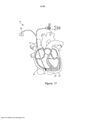
[032] A Figura 1 é uma vista em perspectiva cortada de um coração que mostra o sistema de válvula transcateter do presente invenção posicionado no coração, de acordo com um aspecto;[032] Figure 1 is a cut-away perspective view of a heart showing the transcatheter valve system of the present invention positioned in the heart, according to one aspect;
[033] A Figura 2 é uma vista em elevação lateral de uma amarra, com seus cordões fundidos a suturas, conectado a uma âncora da válvula transcateter da Figura 1, de acordo com um aspecto;[033] Figure 2 is a side elevation view of a tether, with its strands fused to sutures, connected to an anchor of the transcatheter valve of Figure 1, according to an aspect;
[034] A Figura 3A é uma vista em elevação lateral de um sistema de entrega de âncora do sistema de válvula transcateter da Figura. 1, de acordo com um aspecto;[034] Figure 3A is a side elevation view of an anchor delivery system of the transcatheter valve system of Figure. 1, according to an aspect;
[035] A Figura 3B é uma vista em elevação lateral ampliada do sistema de entrega de âncora da Figura 3A;[035] Figure 3B is an enlarged side elevation view of the anchor delivery system of Figure 3A;
[036] A Figura 3C é uma vista de extremidade do sistema de entrega de âncora da Figura 3 A;[036] Figure 3C is an end view of the anchor delivery system of Figure 3A;
[037] A Figura 4A é uma vista em perspectiva do sistema de entrega de âncora da Figura 3, em que uma porção do dispositivo é posicionada no ventrículo direito;[037] Figure 4A is a perspective view of the anchor delivery system of Figure 3, in which a portion of the device is positioned in the right ventricle;
[038] A Figura 4B é uma vista em perspectiva do sistema de entrega de âncora da Figura 3, em que o sistema de entrega de âncora está entregando uma porção da amarra, conectada à âncora, da Figura 2 no ventrículo direito;[038] Figure 4B is a perspective view of the anchor delivery system of Figure 3, wherein the anchor delivery system is delivering a portion of the tether, connected to the anchor, of Figure 2 in the right ventricle;
[039] A Figura 5 A é uma vista em perspectiva do sistema de entrega de âncora da Figura 3, em que o sistema de entrega de âncora está entregando uma porção da amarra, conectada à âncora, da Figura 2 no ventrículo direito;[039] Figure 5A is a perspective view of the anchor delivery system of Figure 3, in which the anchor delivery system is delivering a portion of the tether, connected to the anchor, of Figure 2 in the right ventricle;
[040] A Figura 5B é uma vista em perspectiva da amarra, conectada à âncora, da Figura 2 posicionada no ventrículo direito;[040] Figure 5B is a perspective view of the tether, connected to the anchor, of Figure 2 positioned in the right ventricle;
[041] A Figura 6A é uma vista em perspectiva de duas amarras, em que cada uma é conectada a uma âncora da Figura 2 posicionada em um coração, de acordo com um aspecto;[041] Figure 6A is a perspective view of two tethers, each of which is connected to an anchor of Figure 2 positioned on a heart, according to an aspect;
[042] A Figura 6B é uma vista ampliada das duas amarras, cada uma conectada a uma âncora da Figura 6A;[042] Figure 6B is an enlarged view of the two lanyards, each connected to an anchor of Figure 6A;
[043] A Figura 7A é uma vista em perspectiva de um sistema de entrega de válvula do sistema de válvula transcateter da Figura 1, de acordo com um aspecto, em que uma porção do sistema de entrega de válvula é posicionada no ventrículo direito;[043] Figure 7A is a perspective view of a valve delivery system of the transcatheter valve system of Figure 1, in accordance with an aspect, wherein a portion of the valve delivery system is positioned in the right ventricle;
[044] A Figura 7B é uma vista em perspectiva de uma válvula do sistema de válvula transcateter da Figura 1 de acordo com um aspecto, em que a válvula está sendo posicionada em um anel tricúspide pelo sistema de entrega de válvula da Figura 7 A;[044] Figure 7B is a perspective view of a valve of the transcatheter valve system of Figure 1 according to an aspect, wherein the valve is being positioned in a tricuspid ring by the valve delivery system of Figure 7A;
[045] A Figura 7C é uma vista de extremidade da válvula da Figura 7B;[045] Figure 7C is an end view of the valve of Figure 7B;
[046] A Figura 8A é uma vista em perspectiva de uma válvula do sistema de válvula transcateter da Figura 1, em que a válvula está sendo posicionada no anel tricúspide pelo sistema de entrega de válvula da Figura 7 A;[046] Figure 8A is a perspective view of a valve of the transcatheter valve system of Figure 1, wherein the valve is being positioned on the tricuspid ring by the valve delivery system of Figure 7A;
[047] A Figura 8B é uma vista em perspectiva de uma válvula do sistema de válvula transcateter da Figura 1, em que a válvula foi posicionada no anel tricúspide pelo sistema de entrega de válvula da Figura 7 A;[047] Figure 8B is a perspective view of a valve of the transcatheter valve system of Figure 1, wherein the valve has been positioned on the tricuspid ring by the valve delivery system of Figure 7A;
[048] A Figura 9A é uma vista em perspectiva de uma válvula do sistema de válvula transcateter da Figura 1, em que a válvula está sendo travada na posição no anel tricúspide por travas atriais;[048] Figure 9A is a perspective view of a valve of the transcatheter valve system of Figure 1, in which the valve is being locked into position in the tricuspid ring by atrial locks;
[049] A Figura 9B é uma vista em perspectiva de uma válvula do sistema de válvula transcateter da Figura 1, em que a válvula está travada na posição no anel tricúspide por travas atriais;[049] Figure 9B is a perspective view of a valve of the transcatheter valve system of Figure 1, in which the valve is locked into position in the tricuspid ring by atrial locks;
[050] A Figura 10A é uma vista em elevação de uma trava atrial do sistema de válvula transcateter da Figura 1, de acordo com um aspecto;[050] Figure 10A is an elevation view of an atrial latch of the transcatheter valve system of Figure 1, according to one aspect;
[051] A Figura 10B é uma vista em elevação ampliada da trava atrial da Figura 10A;[051] Figure 10B is an enlarged elevation view of the atrial lock of Figure 10A;
[052] As Figuras 11A a 11D são vistas em elevação progressivas que ilustram a operação da trava atrial da Figura 10A;[052] Figures 11A to 11D are progressive elevation views illustrating the operation of the atrial lock of Figure 10A;
[053] A Figura 12A é uma vista em elevação de uma trava atrial do sistema de válvula transcateter da Figura 1, de acordo com um aspecto;[053] Figure 12A is an elevation view of an atrial latch of the transcatheter valve system of Figure 1, according to one aspect;
[054] A Figura 12B é uma vista em elevação ampliada da trava atrial da Figura 12A;[054] Figure 12B is an enlarged elevation view of the atrial lock of Figure 12A;
[055] A Figura 13A é uma vista em elevação da trava atrial da Figura 12;[055] Figure 13A is an elevation view of the atrial lock of Figure 12;
[056] A Figura 13B é uma vista em corte transversal da trava atrial da Figura 13 A.[056] Figure 13B is a cross-sectional view of the atrial lock of Figure 13A.
[057] As Figuras 14A a 14D são vistas em elevações progressivas que ilustram a operação da trava atrial da Figura 12;[057] Figures 14A to 14D are views in progressive elevation illustrating the operation of the atrial lock of Figure 12;
[058] A Figura 14E é uma vista em perspectiva de uma trava atrial do sistema de válvula transcateter da Figura 1, de acordo com um aspecto;[058] Figure 14E is a perspective view of an atrial latch of the transcatheter valve system of Figure 1, according to one aspect;
[059] A Figura 15A é uma vista em perspectiva do sistema de válvula transcateter da Figura 1 posicionado no coração e com suturas remanescentes;[059] Figure 15A is a perspective view of the transcatheter valve system of Figure 1 positioned in the heart and with sutures remaining;
[060] A Figura 15B é uma vista em perspectiva do sistema de válvula transcateter da Figura 1 posicionado no coração com todos os dispositivos de entrega retraídos;[060] Figure 15B is a perspective view of the transcatheter valve system of Figure 1 positioned in the heart with all delivery devices retracted;
[061] A Figura 16 é uma vista em perspectiva de um sistema de amarra epicárdica para posicionar uma âncora no espaço pericárdico, de acordo com um aspecto;[061] Figure 16 is a perspective view of an epicardial tether system for positioning an anchor in the pericardial space, according to an aspect;
[062] A Figura 17 é uma vista em perspectiva do sistema de amarra epicárdica da Figura 16, em que uma porção de um cateter do sistema entrou no espaço pericárdico.[062] Figure 17 is a perspective view of the epicardial tether system of Figure 16, in which a portion of a catheter of the system has entered the pericardial space.
[063] A Figura 18 é uma vista em perspectiva do sistema de amarra epicárdica da Figura 16, em que o espaço pericárdico foi insuflado.[063] Figure 18 is a perspective view of the epicardial tether system of Figure 16, in which the pericardial space was inflated.
[064] A Figura 19 é uma vista em perspectiva do sistema de amarra epicárdica da Figura 16, em que um fio em J foi inserido no espaço pericárdico insuflado.[064] Figure 19 is a perspective view of the epicardial tether system of Figure 16, in which a J-wire was inserted into the inflated pericardial space.
[065] A Figura 20 é uma vista em perspectiva do sistema de amarra epicárdica da Figura 16, em que uma guia de entrega de âncora do sistema aborda o espaço pericárdico insuflado.[065] Figure 20 is a perspective view of the epicardial tether system of Figure 16, in which a system anchor delivery guide addresses the inflated pericardial space.
[066] A Figura 21 é uma vista em perspectiva do sistema de amarra epicárdica da Figura 16, em que uma âncora do sistema está sendo posicionada no espaço pericárdico insuflado.[066] Figure 21 is a perspective view of the epicardial tether system of Figure 16, in which an anchor of the system is being positioned in the inflated pericardial space.
[067] A Figura 22 é uma vista em perspectiva do sistema de amarra epicárdica da Figura 16, em que uma âncora do sistema foi implantada no espaço pericárdico insuflado.[067] Figure 22 is a perspective view of the epicardial tether system of Figure 16, in which an anchor of the system was deployed in the inflated pericardial space.
[068] A Figura 23 é uma vista em perspectiva do sistema de amarra epicárdica da Figura 16, em que uma âncora do sistema foi implantada no espaço pericárdico insuflado e dispositivos de entrega do sistema foram retraídos;[068] Figure 23 is a perspective view of the epicardial tether system of Figure 16, in which a system anchor was deployed in the inflated pericardial space and system delivery devices were retracted;
[069] A Figura 24 é uma vista em perspectiva de um sistema ventricular entre amarras para posicionar uma âncora no ventrículo esquerdo, de acordo com um aspecto;[069] Figure 24 is a perspective view of a ventricular system between tethers for positioning an anchor in the left ventricle, according to an aspect;
[070] A Figura 25 é uma vista em perspectiva do sistema ventricular entre amarras da Figura 24, em que um fio de RF do sistema cruzou o septo e entrou no ventrículo esquerdo;[070] Figure 25 is a perspective view of the ventricular system between tethers of Figure 24, in which an RF wire from the system has crossed the septum and entered the left ventricle;
[071] A Figura 26 é uma vista em perspectiva do sistema ventricular entre amarras da Figura 24, em que um cateter do sistema cruzou o septo e entrou no ventrículo esquerdo;[071] Figure 26 is a perspective view of the ventricular system between tethers of Figure 24, in which a catheter of the system has crossed the septum and entered the left ventricle;
[072] A Figura 27 é uma vista em perspectiva do sistema ventricular entre amarras da Figura 24, em que um fio em J do sistema foi avançado através do cateter e no ventrículo esquerdo;[072] Figure 27 is a perspective view of the ventricular system between tethers of Figure 24, in which a J-wire of the system has been advanced through the catheter and into the left ventricle;
[073] A Figura 28 é uma vista em perspectiva do sistema ventricular entre amarras da Figura 24, em que uma guia de entrega do sistema aborda o ventrículo esquerdo;[073] Figure 28 is a perspective view of the ventricular system between tethers of Figure 24, in which a system delivery guide addresses the left ventricle;
[074] A Figura 29 é uma vista em perspectiva do sistema ventricular entre amarras da Figura 24, em que a guia de entrega do sistema cruzou o septo e entrou no ventrículo esquerdo;[074] Figure 29 is a perspective view of the ventricular system between tethers of Figure 24, in which the system delivery guide has crossed the septum and entered the left ventricle;
[075] A Figura 30 é uma vista em perspectiva do sistema ventricular entre amarras da Figura 24, em que uma âncora do sistema está sendo posicionada no ventrículo esquerdo;[075] Figure 30 is a perspective view of the ventricular system between tethers of Figure 24, in which a system anchor is being positioned in the left ventricle;
[076] A Figura 31 é uma vista em perspectiva do sistema ventricular entre amarras da Figura 24, em que uma âncora do sistema foi posicionada no ventrículo esquerdo; e[076] Figure 31 is a perspective view of the ventricular system between tethers of Figure 24, in which a system anchor has been positioned in the left ventricle; and
[077] A Figura 32 é uma vista em perspectiva do sistema ventricular entre amarras da Figura 24, em que uma âncora do sistema foi implantada no ventrículo esquerdo e dispositivos de entrega do sistema foram retraídos.[077] Figure 32 is a perspective view of the ventricular system between tethers of Figure 24, in which a system anchor has been deployed in the left ventricle and system delivery devices have been retracted.
[078] A presente invenção é mais prontamente entendida por meio da referência à seguinte descrição detalhada, aos exemplos e às reivindicações, e sua descrição anterior e seguinte. Antes do presente sistema, dispositivos e/ou métodos serem revelados e descritos, deve-se entender que esta invenção não é limitada aos sistemas, dispositivos e/ou métodos específicos revelados a menos que especificado de outro modo, como tal, pode, obviamente, variar. Deve-se entender também que a terminologia usada na presente invenção é com o propósito de descrever aspectos particulares apenas e não é destinada a ser limitante.[078] The present invention is more readily understood by reference to the following detailed description, the examples and the claims, and its preceding and following description. Before the present system, devices and/or methods are disclosed and described, it is to be understood that this invention is not limited to the specific systems, devices and/or methods disclosed unless otherwise specified, as such may, of course, vary. It is also to be understood that the terminology used in the present invention is for the purpose of describing particular aspects only and is not intended to be limiting.
[079] A seguinte descrição da invenção é fornecida como um ensinamento habilitante da invenção em seu melhor aspecto atualmente conhecido. Os indivíduos versados na técnica relevante reconhecerão que muitas alterações são feitas aos aspectos descritos, enquanto ainda obtêm os resultados benéficos da presente invenção. Também será evidente que alguns dos benefícios desejados da presente invenção são obtidos selecionando-se algumas das características da presente invenção sem utilizar outras características. Consequentemente, aqueles que trabalham na técnica reconhecerão que muitas modificações e adaptações à presente invenção são possíveis e ainda podem ser desejáveis em determinadas circunstâncias e são uma parte da presente invenção. Dessa forma, a seguinte descrição é fornecida como ilustrativa dos princípios da presente invenção e não em limitação da mesma.[079] The following description of the invention is provided as an enabling teaching of the invention in its currently known best aspect. Those of skill in the relevant art will recognize that many changes are made to the aspects described, while still obtaining the beneficial results of the present invention. It will also be apparent that some of the desired benefits of the present invention are obtained by selecting some of the features of the present invention without using other features. Consequently, those working in the art will recognize that many modifications and adaptations to the present invention are possible and still may be desirable under certain circumstances and are a part of the present invention. Accordingly, the following description is provided as illustrative of the principles of the present invention and not as a limitation thereof.
[080] Como usado na presente invenção, as formas singulares "um," "uma" e "a/o" incluem referentes plurais a menos que o contexto dite claramente o contrário. Dessa forma, por exemplo, referência a uma "amarra" inclui aspectos que têm duas ou mais amarras a menos que o contexto indique claramente o contrário.[080] As used in the present invention, the singular forms "a," "an" and "a/o" include plural referents unless the context clearly dictates otherwise. Thus, for example, reference to a "string" includes features that have two or more strings unless the context clearly indicates otherwise.
[081] Faixas são expressas na presente invenção como a partir de "cerca de" um valor particular e/ou a "cerca de" outro valor particular. Quando tal faixa é expressa, outro aspecto inclui a partir do um valor particular e/ou ao outro valor particular. De modo similar, quando valores são expressos como aproximações, por meio do uso do antecedente "cerca de," será entendido que o valor particular forma outro aspecto. Será adicionalmente entendido que os pontos finais de cada uma das faixas são significativos tanto em relação ao outro ponto final quanto independentemente do outro ponto final.[081] Ranges are expressed in the present invention as from "about" a particular value and/or to "about" another particular value. When such a range is expressed, another aspect includes from the one particular value and/or to the other particular value. Similarly, when values are expressed as approximations, through the use of the background "about," it will be understood that the particular value forms another aspect. It will be further understood that the endpoints of each of the lanes are significant both in relation to the other endpoint and independently of the other endpoint.
[082] Como usado na presente invenção, os termos "opcional" ou "opcionalmente" significam que o evento ou a circunstância subsequentemente descrita pode ou não ocorrer e que a descrição inclui instâncias em que o dito evento ou circunstância ocorre e instâncias em que o mesmo não ocorre. Como usado na presente invenção, "fluido" se refere a qualquer substância que é livre para fluir e inclui líquidos, gases e plasma. "Comunicação fluida ", como usado na presente invenção se refere a qualquer conexão ou posicionamento relativo que permite que substâncias fluam livremente entre os componentes relevantes.[082] As used herein, the terms "optionally" or "optionally" mean that the event or circumstance subsequently described may or may not occur and that the description includes instances where said event or circumstance occurs and instances where the same does not occur. As used herein, "fluid" refers to any substance that is free to flow and includes liquids, gases and plasma. "Fluid communication" as used in the present invention refers to any connection or relative positioning that allows substances to flow freely between the relevant components.
[083] A revelação na presente invenção se refere a um conjunto médico 10 para implantar uma válvula de modo minimamente invasivo no coração 1 e métodos de implantação de porções do conjunto 10 para alcançar substituição da válvula cardíaca nativa. A Figura 1 ilustra a válvula transcateter 12 que foi implantada a fim de substituir a válvula tricúspide nativa (por exemplo) de acordo com o método revelado na presente invenção e com o conjunto médico 10 revelada na presente invenção. O conjunto compreende uma válvula transcateter 12 que tem uma saia de vedação atrial 14 configurada para acoplar ao assoalho atrial 16 e pelo menos uma amarra 18 configurada para conectar a válvula a pelo menos uma âncora 19 (Figura 2), que se fixa a uma parede intracardíaca, tal como o ápice ventricular 20, como mostrado. A amarra 18 pode ser ancorada por meio de âncora 19 a qualquer parede intracardíaca, incluindo, mas sem limitação, o septo interventricular, o ápice ventricular direito ou a parede livre ventricular direita. Por uma questão apenas de discussão, o ápice ventricular 20 é mostrado, mas é abrangido pelo espírito e escopo da presente invenção, a âncora, a amarra 18 a qualquer parede intracardíaca. O conjunto médico 10 inclui um sistema de entrega de âncora 50 (ilustrado nas Figuras 3 A e 3B) e um conjunto de entrega de válvula 100 (ilustrada na Figura 7A). O método para implantar a válvula transcateter tricúspide como na presente invenção mostrada e descrita inclui, em geral, o método das etapas de: utilizar o sistema de entrega de âncora 50 para entregar a âncora e a amarra para prender a âncora a uma parede intracardíaca, tal como o ápice ventricular; remover o sistema de entrega de âncora 50; utilizar o conjunto de entrega de válvula 100 para posicionar a válvula e a saia; travar a saia atrial; e remover o conjunto de entrega de válvula 100, deixando, desse modo, a válvula no lugar da válvula tricúspide nativa.[083] The disclosure in the present invention relates to a medical kit 10 to implant a valve minimally invasively in the heart 1 and methods of implanting portions of the kit 10 to achieve native heart valve replacement. Figure 1 illustrates the
[084] A válvula transcateter 12 é dimensionada e configurada para substituir a válvula tricúspide entre o átrio direito 2 e o ventrículo direito 3, como ilustrado na Figura 1. Opcionalmente, entretanto, com pequenas variações, a válvula é dimensionada e configurada para ser posicionada no anel mitral entre o átrio esquerdo 4 e o ventrículo esquerdo 5. Consequentemente, então, embora referência seja feita principalmente a dispositivos, sistemas e métodos de substituição de válvula tricúspide, entende-se que com pequenas variações, esses dispositivos, sistemas e métodos podem ser usados para substituir outras válvulas, tais como a válvula mitral, a válvula aórtica, a válvula pulmonar e similares. Por uma questão apenas de discussão, a seguinte descrição e desenhos anexos pertencem a uma válvula tricúspide. Em relação às montagens e aos métodos de entrega, esses podem ser usados e praticados com qualquer dispositivo de substituição de válvula apropriado. A revelação na presente invenção não é limitada à válvula mostrada e descrita.[084] The
[085] Como mostrado, a válvula 12 é uma válvula de autoexpansão (isto é, a válvula é comprimível de modo que a mesma se encaixe através de um cateter do conjunto 10). Em um aspecto, a válvula 12 é composta por nitinol e folhetos de pericárdio bovinos, equinos ou porcinos 19, mostrados na Figura 7C. Em outro aspecto, a válvula 12 tem um diâmetro de válvula que é menor ou aproximadamente igual ao anel no local de liberação 13, tal como o anel tricúspide, impedindo, desse modo, ou reduzindo a aposição ao anel tricúspide frágil. A válvula 12 é operacionalmente conectada a pelo menos uma amarra 18, incluindo pelo menos um cordão 32 para prender a válvula 12 no coração, como descrito abaixo. Pelo menos um furo 15 é definido na parede externa 17 da válvula 12, de acordo com outro aspecto e como ilustrado na Figura 7C. Cada furo 15 é dimensionado e conformado de modo que uma porção de cordão da amarra passe através do furo 15. Dessa forma, cada cordão 32 da amarra 18 é acoplado à válvula sem interferir com qualquer folheto 19 da válvula. Em um aspecto adicional, (não mostrado) a válvula 12 pode ter elementos de ancoramento posicionados ao longo de seu diâmetro externo. Esses elementos de ancoramento permitem fixação adicional a folhetos tricúspides, mas não são necessariamente usados como um mecanismo de fixação primário. Com referência novamente à Figura 1, uma saia de vedação atrial 14 se estende de modo substancialmente circunferencial ao redor da extremidade superior da válvula transcateter 12. A saia 14 é coberta com uma membrana e tem um diâmetro maior que o anel no local de liberação 13. Por exemplo, a saia de vedação 22 pode ter um diâmetro de saia maior que o diâmetro do anel tricúspide. Em outro aspecto, a saia atrial é formada por, mas sem limitação, materiais sintéticos a partir das classes que consistem em policarbonato, poliuretano, poliéster, politetrafluoroetileno expandido (ePTFE), tereftalato polietileno (PET), silicone, borrachas naturais ou sintéticas ou uma combinação dos mesmos. A saia atrial também pode ser coberta com pericárdio bovino, ovino, equino ou porcino adultos ou jovens. Opcionalmente, pelo menos uma porção da saia atrial 14 é formada a partir de materiais alternativos, tal como, por exemplo e sem limitação, espuma de poliuretano ou anel inflável por solução salina, com a capacidade para troca polimérica para solidificação do anel.[085] As shown,
[086] Em um aspecto, a saia de vedação atrial 14 compreende adicionalmente pelo menos uma âncora atrial 238, tal como membro que se projetam através de um orifício de saída de âncora 242 permite estabilidade no átrio. Estabilidade no átrio impede, desse modo, migração retrógrada da válvula 12, tal como no evento de disfunção de âncora ventricular e similares.[086] In one aspect, the
[087] Em outro aspecto, pelo menos uma porção da saia de vedação atrial 14 tem um ou mais membros de fixação 24, ilustrados na Figura 15B, posicionados ao longo de sua borda inferior, permitindo ancoramento adicional ao assoalho atrial direito 16 e/ou outras porções no lado atrial do anel tricúspide, impedindo migração da válvula 12 no átrio direito proximal 2, impedindo, desse modo, a instabilidade (por exemplo, balanço) e regurgitação paravalvular de prótese. Além disso, a saia atrial 14 se conforma à topografia do assoalho atrial, incluindo a capacidade de cobrir e vedar cabos intracardíacos, tal como cabos de marca-passo permanentes. A capacidade da saia atrial 14 para vedar sobre fios e impedir regurgitação ao redor dos mesmos distingue esse sistema de válvula transcateter de outros sistemas de reparo tricúspide transcateter.[087] In another aspect, at least a portion of the
[088] Com referência agora à Figura 2, o pelo menos uma amarra 18 é operacionalmente conectado à válvula de substituição 12 e conecta a válvula 12 à âncora 19. A amarra 18 inclui pelo menos um cordão 32 e cada cordão 32 é conectado a uma sutura 34. A âncora 19 inclui um parafuso de âncora 28 e um tampão de âncora 30. Em um aspecto, o parafuso de âncora é acoplado a e se estende a partir de uma extremidade distal 36 do tampão de âncora e a pelo menos um cordão 32 da amarra 18 é acoplado a e se estende a partir de uma extremidade proximal 38 do tampão de âncora 30. Isto é, o tampão de âncora 30 é posicionado entre o parafuso de âncora 28 e o cordão 32. O parafuso de âncora 28, da âncora 19, é configurado para fixar seguramente a amarra 18 a uma parede intracardíaca, tal como o ápice ventricular 20 do coração 1. Por exemplo, o parafuso de âncora 28 é um parafuso de fixação ativo que compreende linhas ou uma bobina que é seguramente rotacionada no ápice ventricular. A âncora, por meio do parafuso de âncora, é configurada para fixar seguramente a amarra a uma parede intracardíaca, tal como o ápice ventricular 20 do coração, sem se estender através do ápice e para fora do coração. Dessa forma, nesse aspecto, substancialmente nenhuma porção do conjunto 10 penetra completamente e/ou se estende completamente através de qualquer porção da parede cardíaca e acesso transapical não é necessário. Em um aspecto adicional (não mostrado), em vez do parafuso de âncora 28, um mecanismo de fixação composto por, mas sem limitação, nitinol, aço inoxidável, cobalto-crômio ou ligas de titânio, no formato de espigas, ganchos, pontas e similares é posicionado na extremidade distal 36 do tampão de âncora 30 para fixar seguramente a amarra 18 ao ápice ventricular 20 do coração 1 sem se estender através do ápice e para fora do coração.[088] Referring now to Figure 2, the at least one
[089] O pelo menos um cordão 32 tem uma extremidade distal 40 acoplado a uma porção do tampão de âncora 30 e uma extremidade proximal 42 acoplada à sutura 34. Em um aspecto, o cordão é um cordão forte, mas flexível, tal como, por exemplo e sem limitação, um cordão de politetrafluoroetileno expandido (ePTFE) ou polietileno de peso molecular ultra-alto (UHMWPE ou UHMW). Em uso, descrito mais completamente abaixo, uma porção central do cordão 32 (entre a extremidade distal e a extremidade proximal) se estende através e/ou é acoplado à válvula 12 para reter a válvula na posição desejada em relação ao anel tricúspide.[089] The at least one
[090] Com referência agora às Figuras 3A a 3C, 4A e 4B, o sistema de entrega de âncora 50 para posicionar e implantar o tampão de âncora 30 da âncora 19 na posição desejada é ilustrado. O sistema de entrega 50 compreende uma guia de entrega de âncora 52 e uma haste de entrega de âncora 54. Nesse aspecto, a guia de entrega de âncora 52 tem uma extremidade distal 56, uma extremidade proximal oposta 58 e um lúmen interno da guia 57 que se estendem entre a ponta de guia de entrega de âncora 60 e a extremidade proximal oposta 58 e é configurado de modo que pelo menos uma porção da haste de entrega de âncora 54 se estenda através do mesmo. Em outro aspecto, pelo menos uma porção da guia de entrega de âncora 52 é flexível de modo que uma ponta 60 na extremidade distal da guia de entrega de âncora 52 seja posicionada em um local de ancoramento da parede intracardíaca 62, tal como o ápice ventricular 20, ou adjacente à mesma.[090] Referring now to Figures 3A to 3C, 4A and 4B, the
[091] A haste de entrega de âncora 54 é configurada para fixar seguramente o parafuso de âncora 28 ao local de ancoramento 62. A haste de entrega de âncora 54 tem uma extremidade distal 64, uma extremidade proximal oposta 66 e um lúmen interno de haste 59 que se estende entre as mesmas, em que o lúmen interno de haste 59 é dimensionado e configurado de modo que pelo menos uma porção do pelo menos uma amarra 18 seja inserida através do mesmo. Em outro aspecto, pelo menos uma porção da haste de entrega de âncora 54 é flexível de modo que uma ponta de haste 68 na extremidade distal da haste de entrega de âncora 54 seja posicionada no local de ancoramento de parede intracardíaca 62, tal como o ápice ventricular 20, ou adjacente ao mesmo.[091] Anchor delivery rod 54 is configured to securely
[092] Como mostrado na Figura 3B, um furo ou um soquete 70 é definido na ponta de haste 68 da haste de entrega de âncora 54. O soquete é dimensionado e configurado para engatar de modo correspondente o tampão de âncora 30. Isto é, pelo menos uma porção do tampão de âncora é posicionada no soquete 70 de modo que paredes 72 do soquete engatem o tampão de âncora. Dessa forma, por exemplo, quando o tampão de âncora 30 é posicionado no soquete 70 e engata no mesmo, a rotação da haste de entrega de âncora 54 rotaciona o tampão de âncora 30. Consequentemente, o soquete engata o tampão de âncora 30 e o parafuso de âncora 28 se estende distalmente a partir da haste de entrega de âncora 54, como ilustrado na Figura 3B. Em um aspecto adicional, quando o soquete 70 engata o tampão de âncora 30, a pelo menos um cordão 32 e pelo menos uma porção da pelo menos uma sutura 34 se estendem através do lúmen interno de haste da haste de entrega de âncora 54.[092] As shown in Figure 3B, a hole or
[093] O sistema de entrega de âncora 50 compreende adicionalmente um botão de guia 74 com uma alça de deflexão 76 acoplada à guia de entrega de âncora 52. O botão de guia e a alça de deflexão são configurados e usados para ajudar a guiar a ponta 60 da guia de entrega de âncora até a local de ancoramento da parede intracardíaca 62, tal como o ápice ventricular 20. Como mostrado na Figura 3A, o sistema de entrega de âncora 50 inclui um botão de haste 78 acoplado à haste de entrega de âncora 54. Em uso, descrito mais completamente abaixo, a rotação do botão de haste 78 rotaciona de modo correspondente a ponta de haste 68 e o tampão de âncora 30 quando o tampão de âncora 30 é recebido dentro do soquete 70.[093] The
[094] O sistema de entrega de âncora 50 inclui uma bainha 80 acoplada de modo removível à guia de entrega de âncora 52. A bainha 80 está em comunicação fluida com a guia de entrega de âncora 52 de modo que fluidos, tais como dióxido de carbono e similares cerquem a guia de entrega de âncora através da bainha. Um canal de bainha central 84 é definido pela bainha 80 que está em comunicação com a guia de entrega de âncora 52 de modo que a haste de entrega de âncora 54 e outros componentes de sistema se estenda através do canal de bainha central 84.[094]
[095] O sistema de entrega de âncora 50 opcionalmente inclui um fio em J 82, como mostrado nas Figuras 7 A, 7B, 8A e 8B, que é guiável pelo usuário até o local de ancoramento 62. O fio em J é, por exemplo e sem limitação, um fio em J de 0,635 mm (0,025") ou 0,889 mm (0,035"). Obviamente, fios em formato de J que têm outros diâmetros são contemplados. Como em qualquer sistema através de fios, o fio em J é introduzido primeiro por meio da bainha 80 no átrio direito 3, através do local de liberação 13, no ventrículo direito 3, até o local de ancoramento 62. Fornecendo-se uma trajetória para a guia de entrega de âncora 52 traçar até seu alvo final, um fio em J aumenta a eficiência e segurança dessa etapa.[095] The
[096] Para instalar a válvula 12 no anel tricúspide, como mostrado na Figura 4 A, o fio em J 82, que serve como um fio de guia, é inserido na veia jugular interna direita, entra no átrio direito e aborda o local de liberação de âncora 62. O sistema de entrega de âncora 50 é guiado pelo usuário, ao longo do comprimento do fio em J anteriormente implantado 82, até o local de ancoramento da parede intracardíaca 62, tal como o ápice ventricular 20. A ponta de guia de entrega de âncora 60 na extremidade distal 56 da guia de entrega de âncora 52 é posicionada no local de ancoramento, tal como o ápice ventricular, ou adjacente ao mesmo. Como mostrado na Figura 3A, a haste de entrega de âncora 54 e a amarra 18, conectados ao tampão de âncora 30 e ao parafuso de âncora 28 da âncora 19, são posicionados dentro do lúmen interno da guia 57 da guia de entrega de âncora 52. O tampão de âncora 30 é acoplado à extremidade distal 64 da haste de entrega de âncora 54 com o cordão 32 da amarra 18 posicionado no lúmen 59 da haste de entrega de âncora 54. A haste de entrega de âncora 54 é avançada distalmente através do lúmen interno da guia da guia de entrega de âncora 52 até que o tampão de âncora 30 acoplado à extremidade distal da haste de entrega de âncora 54 seja posicionado no local de ancoramento da parede intracardíaca 62, tal como o ápice ventricular 20, ou adjacente ao mesmo.[096] To install
[097] Com o parafuso de âncora 28 da âncora 19, conectado à amarra 18 por meio da âncora 30, posicionado adjacente ao local de ancoramento 62, a extremidade proximal 66 da haste de entrega de âncora 54 é rotacionada para causar rotação correspondente do tampão de âncora 30, como ilustrado na Figura 4B. Por exemplo, a alça rotativa 78 é rotacionada em uma primeira direção para causar rotação correspondente do tampão de âncora. O parafuso de âncora acoplado ao tampão de âncora 30 também rotaciona e se aparafusa em uma porção do local de ancoramento da parede intracardíaca 62, tal como o ápice ventricular 20, até que a extremidade distal 36 do tampão de âncora esteja adjacente à parede intracardíaca e/ou a amarra esteja seguramente fixado à parede. Observe que, nessa posição, o parafuso de âncora 28 não se estende completamente através de qualquer porção do parede cardíaca e acesso transapical não é necessário. Mediante colocação do tampão de âncora 30 na posição desejada, a haste de entrega de âncora 54 e a guia de entrega de âncora 52 do sistema de entrega de âncora 50 são retraídas do coração 1, como ilustrado na Figura 5A. Como tal, na Figura 5B, os cordões 32 da amarra 18, acoplados ao tampão de âncora 30, são presas pelo parafuso de âncora 28 da âncora 19 e permanecem dentro do ventrículo direito e o sistema de entrega de válvula 100 é implantado.[097] With
[098] Como mostrado na Figura 5B, após a colocação do tampão de âncora 30 da âncora 19, a pelo menos um cordão 32 da amarra 18 se estende a partir do tampão de âncora através do anel tricúspide e no átrio direito 2. Uma sutura 34 é acoplada à extremidade proximal de cada cordão e se estende através da veia cava superior (ou inferior) e para fora do coração 1.[098] As shown in Figure 5B, after placement of the anchor plug 30 of
[099] Se mais de uma amarra 18, conectada a uma âncora 19, for entregue, cada âncora 19 é presa por seu parafuso de âncora 28 e esse processo é repetido até que todos as amarras, conectadas a âncoras, tenham sido seguramente fixadas à parede cardíaca. Em um aspecto e como ilustrado nas Figuras 6 A e 6B, o conjunto 10 utiliza duas âncoras e amarras, três âncoras e amarras, quatro âncoras e amarras ou mais âncoras e amarras também são contemplados.[099] If more than one
[0100] Com o parafuso de âncora 28 preso ao ápice ventricular e a amarra 18 no lugar, o conjunto de entrega de válvula 100 pode, agora, ser utilizada para introduzir e posicionar a válvula 12.[0100] With
[0101] Com referência agora às Figuras 7 A e 7B, o conjunto de entrega de válvula 100 para posicionar e implantar a válvula 12 no local de liberação desejado 13 é ilustrado. Como mostrado, o conjunto de entrega de válvula 100 compreende uma guia de entrega de válvula 102, uma ponta cônica 104, um botão de liberação de válvula 106 e pelo menos uma haste de posicionamento atrial 108. Nesse aspecto, a guia de entrega de válvula tem uma extremidade distal 110, uma extremidade proximal oposta 112 e um lúmen interno da guia 114 que se estende entre as mesmas, em que o lúmen interno da guia é dimensionado e configurado de modo que a válvula 12 e outros componentes de sistema sejam estendidos através do mesmo. Em outro aspecto, pelo menos uma porção da guia de entrega de válvula 102 é flexível de modo que uma ponta 116 na extremidade distal da guia de entrega de válvula seja posicionada após o local de liberação 13 e no ventrículo direito 3.[0101] Referring now to Figures 7A and 7B, the valve delivery assembly 100 for positioning and deploying the
[0102] O botão de posicionamento liberação de válvula 106 é acoplado à extremidade proximal 112 da guia de entrega de válvula 102. Um canal central 118 é definido pelo botão de liberação de válvula 106 e está em comunicação fluida com o lúmen interno da guia 114 de modo que a haste de posicionamento atrial 108, o fio em J 82 e/ou a pelo menos uma sutura 34 se estendam através do canal central 118 e no lúmen interno da guia 114. Em outro aspecto, o botão de liberação de válvula 106 é rotativo e configurado de modo que a rotação da alça 106 em uma primeira direção faça com que a bainha 102 ao redor da válvula 12 seja removida. A ponta cônica 104 pode ser uma ponta cônica convencional acoplada à guia de entrega de válvula 102 e configurada para guiar a válvula 12 até o local de liberação 13.[0102] The valve
[0103] Com referência às Figuras 8A e 8B, a pelo menos uma haste de posicionamento atrial 108 tem uma extremidade distal 120, uma extremidade proximal oposta 122 e um lúmen interno de haste 124 que se estende entre as mesmas, em que o lúmen interno de haste é dimensionado e configurado de modo que uma porção de uma sutura 34 e/ou um cordão 32 seja inserido através das mesmas. Em outro aspecto, pelo menos uma porção da haste de posicionamento atrial 108 é flexível de modo que a extremidade distal 120 da haste de posicionamento atrial seja posicionada no local de liberação 13 ou adjacente ao mesmo.[0103] Referring to Figures 8A and 8B, the at least one
[0104] A pelo menos uma haste de posicionamento atrial 108 compreende uma trava destacável 126 posicionada na extremidade distal 120 da haste ou adjacente à mesma, como ilustrado nas Figuras 9 a 14. Em um aspecto, a trava destacável é configurada para fixar seguramente a pelo menos um cordão 32 a uma porção do átrio direito 2. Dessa forma, a extremidade distal 40 do cordão é seguramente fixada ao tampão de âncora 30 no ventrículo direito 3 e a trava destacável 126 fixa seguramente o cordão 32 no átrio direito.[0104] The at least one
[0105] As Figuras 10A, 10B e 11A a 11D ilustram uma modalidade da trava destacável 126. Em um aspecto, a trava tem uma primeira extremidade 128, uma segunda extremidade oposta 130 e uma parede lateral 132 que cooperam para definir uma cavidade central 134. Em outro aspecto, a primeira extremidade é rosqueada e configurada para engatar de modo correspondente linhas complementares na extremidade distal 120 da haste de posicionamento atrial 108. Uma abertura 136 é definida em cada uma dentre a primeira e a segunda extremidades da trava 126 de modo que uma porção do cordão 32 se estenda através de ambas as aberturas e através da cavidade central. Em uso, descrito mais completamente abaixo, a trava destacável é seletivamente fixada à haste de posicionamento atrial rotacionando-se a haste 108 em uma primeira direção, e a trava destacável 126 é seletivamente destacável da haste de posicionamento atrial rotacionando-se a haste 108 em uma segunda direção que é oposta à primeira direção.[0105] Figures 10A, 10B and 11A to 11D illustrate an embodiment of the
[0106] Em um aspecto, a trava destacável 126 compreende adicionalmente um grampo 138 móvel ao redor e entre uma primeira posição travada, em que uma porção do grampo prende o cordão 32 na posição desejada, e uma segunda posição destravada, em que o grampo não prende o cordão na posição desejada. Um membro de polarização 140, tal como uma mola e similares, é configurado para fazer com que o grampo 138 vá para a primeira posição travada. Uma aba 135 ou outra protrusão que se estende para longe da extremidade distal 120 da haste de posicionamento atrial 108 é configurada para manter o grampo na segunda posição destravada quando a trava destacável é fixada à haste 108.[0106] In one aspect, the
[0107] As Figuras 12A a 14D ilustram outra modalidade de uma trava destacável 226. Em um aspecto, a trava tem uma primeira extremidade 228, uma segunda extremidade oposta 230 e uma parede lateral 232 que cooperam para definir uma cavidade central 234. Em outro aspecto, a primeira extremidade é rosqueada e configurada para engatar de modo correspondente linhas complementares na extremidade distal 120 da haste de posicionamento atrial 108. Uma abertura 236 é definida em cada uma dentre a primeira e a segunda extremidades da trava 226 de modo que uma porção do cordão 32 se estenda através de ambas as aberturas e através da cavidade central. Em uso, descrito mais completamente abaixo, a trava destacável é seletivamente fixada à haste de posicionamento atrial rotacionando-se a haste 108 em uma primeira direção e a trava destacável 226 é seletivamente desafixada da haste de posicionamento atrial rotacionando-se a haste 108 em uma segunda direção que é oposta à primeira direção.[0107] Figures 12A to 14D illustrate another embodiment of a
[0108] Em um aspecto, a trava destacável 226 compreende adicionalmente uma âncora atrial 238 móvel ao redor e entre uma primeira posição travada, em que uma porção da âncora atrial prende o cordão 32 na posição desejada e uma segunda posição destravada, em que a âncora atrial não prende o cordão na posição desejada. Um membro de polarização 240, tal como uma mola e similares, é configurado para fazer com que a âncora atrial 238 vá para a primeira posição travada. Uma aba 135 ou outra protrusão que se estende para longe da extremidade distal 120 da haste de posicionamento atrial 108 é configurada para manter a âncora atrial na segunda posição destravada quando a trava destacável está fixada à haste 108.[0108] In one aspect, the
[0109] Em um aspecto, um orifício de saída de âncora 242 é definida em uma porção da parede lateral 232 da trava destacável 226. Nesse aspecto, o orifício de saída de âncora é dimensionado e conformado de modo que, na primeira posição travada, um gancho 244 ou outro elemento de pega posicionado em uma ponta da âncora atrial 246 se estende através do orifício 242 e para fora da cavidade central 234. Em uso, na primeira posição travada, o gancho ancora seguramente a trava destacável (e, dessa forma, o cordão 32) a uma porção do átrio 2. Com referência à Figura 15, o conjunto 10 compreende adicionalmente um cortador de sutura 148 dimensionado e configurado para passar através da pelo menos uma sutura 34 através da bainha de entrega de válvula 80 para cortar a pelo menos uma sutura 34.[0109] In one aspect, an
[0110] Em uso, o conjunto 10 implanta a válvula 12 com uma abordagem transcateter colocando-se uma âncora ventricular direita primeiro. A posição de válvula não exigiria puxar uma amarra 18 através de uma parede intracardíaca, tal como o ápice ventricular 20 do coração 1, devido ao fato de que a válvula 12 se move livremente sobre a amarra até que a posição desejada de válvula seja alcançada. Após a posição desejada de válvula ser alcançada, a pelo menos uma haste de posicionamento atrial 108 faz com que a saia de vedação atrial 14 vá para a posição e seja travada no lugar por meio de uma trava destacável 126, 226 na extremidade de cada haste de posicionamento. A válvula é reposicionada ou recuperada até a entrega das suturas 34 que se estendem através de cada haste de posicionamento atrial 108.[0110] In use, set 10
[0111] Figura 14E ilustra outra modalidade de uma trava destacável 526. Em um aspecto, a trava tem uma primeira extremidade 528, uma segunda extremidade oposta 530 e uma parede lateral 532 que cooperam para definir uma cavidade central 534. Em outro aspecto, a primeira extremidade é rosqueada e configurada para engatar de modo correspondente linhas complementares na extremidade distal 120 da haste de posicionamento atrial 108. Uma abertura 536 é definida em cada uma dentre a primeira e a segunda extremidades da trava 526 de modo que uma porção do cordão 32 se estenda através de ambas as aberturas e através da cavidade central. Em uso, descrito mais completamente abaixo, a trava destacável é seletivamente fixada à haste de posicionamento atrial rotacionando-se a haste 108 em uma primeira direção e a trava destacável 526 é seletivamente desafixada da haste de posicionamento atrial rotacionando-se a haste 108 em uma segunda direção que é oposta à primeira direção.[0111] Figure 14E illustrates another embodiment of a
[0112] Em um aspecto, a trava destacável 526 compreende adicionalmente pelo menos uma âncora atrial 538 móvel ao redor de e entre uma primeira posição travada, em que uma porção da âncora atrial prende o cordão 32 na posição desejada, e uma segunda posição destravada, em que a âncora atrial não prende o cordão na posição desejada. Opcionalmente, a âncora atrial compreende uma primeira âncora atrial 542 e uma segunda âncora atrial 544. Em outro aspecto, a âncora atrial compreende um braço de alavanca de came. Um membro de polarização 540, tal como uma mola e similares, é configurado para fazer com que a âncora atrial 538 vá para a primeira posição travada. Em um aspecto adicional, o membro de polarização é um polímero comprimível. Uma aba 135 ou outra protrusão que se estende para longe da extremidade distal 120 da haste de posicionamento atrial 108 é configurada para manter a âncora atrial na segunda posição destravada quando a trava destacável está fixada à haste 108.[0112] In one aspect, the
[0113] Em um aspecto, um orifício de saída de âncora 546 é definido em uma porção da parede lateral 532 da trava destacável 526. Nesse aspecto, o orifício de saída de âncora é dimensionado e conformado de modo que, na primeira posição travada, uma porção 548 da âncora atrial 538 se estenda através do orifício 546 e para fora da cavidade central 534. Em uso, na primeira posição travada, a âncora atrial ancora seguramente a trava destacável (e, dessa forma, o cordão 32) a uma porção do átrio 2.[0113] In one aspect, an
[0114] Com referência à Figura 15, o conjunto 10, opcionalmente, compreende adicionalmente um cortador de sutura 148 dimensionado e configurado para passar através da bainha de entrega de válvula 80 para cortar a pelo menos uma sutura 34.[0114] Referring to Figure 15, the assembly 10 optionally further comprises a suture cutter 148 sized and configured to pass through the
[0115] Em uso, o conjunto 10 implanta a válvula 12 com uma abordagem transcateter colocando-se uma âncora ventricular direita primeiro. A posição de válvula não exigiria puxar uma amarra 18 através de uma parede intracardíaca, tal como o ápice ventricular 20, do coração 1, devido ao fato de que a válvula 12 se move livremente ao longo da amarra até que a posição desejada de válvula seja alcançada. Após a posição desejada de válvula ser alcançada, a pelo menos uma haste de posicionamento atrial 108 faz com que a saia de vedação atrial 14 vá para a posição e seja travada no lugar por meio de uma trava destacável 126, 226 na extremidade de cada haste de posicionamento. A válvula é reposicionada ou recuperada até a entrega das suturas 34 que se estendem através de cada haste de posicionamento atrial 108.[0115] In use, set 10
[0116] Com referência agora à Figura 7A, o conjunto de entrega de válvula 100 pode, então, ser inserida através do fio em J 82 e em uma porção do coração 1. Antes de a guia de entrega de válvula 102 ser inserida na bainha 80 em rota até o coração, a válvula 12 é pré-carregada na extremidade distal 110 da guia de entrega de válvula 102. Pelo menos uma porção da sutura 34 é rosqueada através do pelo menos um furo 15 definido na parede externa 17 da válvula 12, ilustrada nas Figuras 7B e 7C, rastreando no lúmen interno da guia 114 da guia de entrega de válvula 102. Como a válvula 12, dentro da extremidade distal 110, e a guia de entrega de válvula 102 se movem como uma unidade ao longo do fio em J 82, uma porção da pelo menos um cordão pode se estender através e para longe da extremidade distal 110 da guia de entrega de válvula, e uma porção da pelo menos uma sutura pode se estender através e para longe da extremidade proximal 112 da guia de entrega de válvula 102. A guia de entrega de válvula é posicionada de modo que a ponta 116 na extremidade distal da guia de entrega de válvula 102 seja passada através do local de liberação 13 e no ventrículo direito 3.[0116] Referring now to Figure 7A, the valve delivery assembly 100 can then be inserted through the J-
[0117] A válvula 12, que foi pré-carregada na extremidade distal 110 da guia de entrega de válvula 102, é posicionada no local de liberação 13. Em um aspecto, e antes da inserção na guia de entrega de válvula, cada sutura 34 é rosqueada através do pelo menos um furo 15 definido na parede externa 17 da válvula 12, ilustrada nas Figuras 7B e 7C. Em outro aspecto, furos similares (não mostrado) são definidos na saia de vedação atrial 14 de modo que cada sutura seja rosqueada através do furo definido na saia de vedação. Como a válvula 12 e a guia de entrega de válvula 102 são movidas como uma unidade em direção ao local de liberação, a válvula 12 alcançará a extremidade da sutura e uma porção do cordão 32 se tornará rosqueada através do furo 15 definido na válvula. Em um aspecto, a válvula 12 e a guia de entrega de válvula 102 podem deslizar para cima e para baixo a pelo menos um cordão até que o local de liberação desejado 13 tenha sido alcançado. Isto é, a válvula está flutuando livremente no cordão 32 até que seja travada no lugar pela trava destacável 126, 226.[0117] The
[0118] Como é apreciado, com a válvula 12 no local de liberação desejado posicionamento , o botão de posicionamento liberação de válvula 106 retrai a extremidade distal 110 da guia de entrega de válvula 102 enquanto a válvula 12 permanece fixa em posição, desse modo, "tirando a bainha" da válvula 12 de modo que a válvula e/ou a saia de vedação atrial 14 se expanda para seu tamanho total descomprimido. Opcionalmente, em um aspecto, devido ao fato de que a posição de válvula é ajustada, o botão de posicionamento liberação de válvula 106 é usado para retrair a extremidade distal 110 da guia de entrega de válvula 102, desse modo, "tirando a bainha" da válvula 12 de modo que a válvula e/ou a saia se expanda para seu tamanho completo descomprimido com a válvula próxima ao local de liberação desejado.[0118] As appreciated, with the
[0119] Uma haste de posicionamento atrial 108 é, então, inserida através de cada sutura 34 de modo que uma porção de cada sutura esteja no lúmen interno de haste 124 e uma porção de cada sutura se estenda da extremidade proximal 122 da haste de posicionamento. Com referência às Figuras 8A e 8B, a haste de posicionamento 108 é inserida através da guia de entrega de válvula 102 até que uma porção do cordão 32 esteja no lúmen interno de haste e a extremidade distal 120 da haste de posicionamento (com a trava destacável 126, 226 fixada à mesma) seja adjacente à saia de vedação atrial 14. As hastes de posicionamento 108 são empurradas para baixo pelo usuário até que a saia de vedação esteja em uma posição desejada em relação ao anel tricúspide. Com a saia de vedação 14 e a válvula 12 em uma posição desejada no local de liberação 13, cada sutura 34 é puxada de modo esticado pelo usuário, o qual, por sua vez, puxará de modo frouxo através do lúmen interno de haste 124 até que cada cordão 32 esteja esticado. Por exemplo, a extremidade de uma sutura que se estende da extremidade proximal 122 da haste de posicionamento atrial é puxada por um usuário para ajustar a tensão no cordão correspondente. Em um aspecto, tensão diferencial é aplicada ao cordão 32 ajustando-se a força aplicada à sutura 34. Por exemplo, se o usuário puxar uma primeira sutura mais forte que uma segunda sutura 34, a tensão no cordão 32 que corresponde à primeira sutura é maior que a tensão no cordão acoplado à segunda sutura 34.[0119] An
[0120] Com referência agora às Figuras 9A e 9B, cada haste de posicionamento atrial 108 é, então, rotacionada em uma primeira direção para travar cada trava destacável 126, 226 contra a saia de vedação atrial 14 e ao cordão 32. Dessa forma, a válvula 12 é travada pela trava destacável no lado atrial do anel tricúspide. Rotação contínua na primeira direção desafixa a trava 126, 226 da haste de posicionamento. Quando a trava tiver sido desafixada da haste de posicionamento 108, a haste é retraída do coração 1 através da guia de entrega de válvula 102. Com as hastes de posicionamento 108 retraídas, o cordão 32 do pelo menos uma amarra 18 acopla a válvula à parede de âncora intracardíaca, tal como o ápice ventricular 20. A trava destacável 126, 226 na posição travada impede que a extremidade proximal 42 do cordão se mova em relação à saia de vedação 14, fixando, desse modo, seguramente a válvula 12 no lugar no local de liberação 13.[0120] Referring now to Figures 9A and 9B, each
[0121] Como ilustrado nas Figuras 15A e 15B, com a válvula 12 seguramente fixa no local de liberação 13, o cortador de sutura 148 é avançado ao longo das suturas 34 e até a trava destacável 126, 226. O cortador de sutura, então, corta a extremidade distal de cada sutura logo acima da trava destacável. As suturas e o cortador de sutura são, então, removidos do coração 1.[0121] As illustrated in Figures 15A and 15B, with the
[0122] Em um aspecto, antes de cortar as suturas 34, a válvula 12 é recuperada ou reposicionada. Por exemplo, se for determinado que a válvula deve ser removida ou reposicionada, uma haste de posicionamento atrial 108 é posicionada ao longo de cada sutura de modo que uma porção da sutura esteja no lúmen interno de haste 124. Quando a extremidade distal 120 da haste de posicionamento é adjacente ou está em contato com a trava destacável 126, 226, a rotação da haste de posicionamento 108 em uma segunda direção que é oposta à primeira direção fixa a trava destacável à extremidade distal da haste de posicionamento. Rotação contínua na segunda direção destrava a trava do cordão 32. Com cada cordão destravado, a válvula é removida e/ou reposicionada no local de liberação 13.[0122] In one aspect, prior to cutting
[0123] Em outro aspecto, a válvula 12 poderia ser reposicionada e/ou removida dias a semanas após o liberação de válvula. Nesse aspecto, as suturas não são cortadas, mas embrulhadas ao redor de um carretel ou outro dispositivo de embalagem. Esse dispositivo poderia, então, ser fixado à saia atrial 14 da válvula 12. Dias após o liberação da válvula e conclusão do procedimento, o carretel/dispositivo de embalagem poderia ser recapturado, permitindo a desmontagem e a recuperação das suturas. Uma haste de posicionamento atrial 108 poderia ser posicionada ao longo de cada sutura de modo que uma porção da sutura esteja no lúmen interno de haste 124. Quando a extremidade distal 120 da haste de posicionamento é adjacente ou está em contato com a trava destacável 126, 226, a rotação da haste de posicionamento 108 na segunda direção que é oposta à primeira direção fixa a trava destacável à extremidade distal da haste de posicionamento. Rotação contínua na segunda direção destrava a trava do cordão 32. Com cada cordão destravado, a válvula é removida e/ou reposicionada no local de liberação 13.[0123] In another aspect,
[0124] Em uma modalidade, ilustrada nas Figuras 16 a 23, o conjunto 10 compreende um sistema de amarra epicárdica 300 para posicionar uma âncora 302 no espaço pericárdico 304. Em um aspecto, a amarra epicárdica compreende um cateter 306, uma linha de gás CO2 308 e um coletor 310. Em outro aspecto, o cateter é um microcatéter que tem uma extremidade distal 312 configurada para ser aparafusada e/ou de outro modo impulsionada através de pelo menos uma porção da parede do coração 1. Por exemplo, e como ilustrado na Figura 16, a extremidade distal do microcatéter engata no endocárdio 314 do coração. O microcatéter 306 também tem uma extremidade proximal 316 oposta à extremidade distal e um lúmen interno de cateter 318. A extremidade proximal do microcatéter é acoplada à linha de gás CO2 308 e o coletor 310 de modo que a linha de gás CO2 e o coletor estejam em comunicação fluida vedada com o lúmen interno de cateter.[0124] In one embodiment, illustrated in Figures 16 to 23, the assembly 10 comprises an
[0125] Com referência agora à Figura 17, a extremidade distal 312 do microcatéter 306 é impulsionada através da parede cardíaca até que a extremidade distal do microcatéter esteja posicionada no espaço pericárdico 304 pelo pericárdio 320. Em um aspecto, um agente de contraste 322 é injetado a partir do coletor 310 através do lúmen interno de cateter 318 e no espaço pericárdico para verificar que a extremidade distal 312 do microcatéter 306 esteja no espaço pericárdico 304.[0125] Referring now to Figure 17, the
[0126] Uma vez que a extremidade distal 312 do microcatéter 306 foi posicionada no espaço pericárdico 304, dióxido de carbono é injetado a partir da linha de gás CO2 308 através do lúmen interno de cateter 318 e no espaço pericárdico 304 para insuflar o espaço, ilustrado na Figura 18.[0126] Once the
[0127] Em um aspecto, o fio em J 82 é, então, avançado através do lúmen interno de cateter318 e no espaço pericárdico 304, como ilustrado na Figura 19. Com o fio em J no lugar, o cateter 306 é removido do coração 1.[0127] In one aspect, the J-
[0128] Em outro aspecto, ilustrado nas Figuras 20 e 21, a guia de entrega de âncora 52 é inserida através do fio em J 82 até que a ponta 60 na extremidade distal 56 da guia de entrega de âncora esteja posicionada em um local de ancoramento 324 no espaço pericárdico 304 ou adjacente ao mesmo. A haste de entrega de âncora 54 é inserida através do lúmen interno da guia da guia de entrega de âncora 52 até que a extremidade distal 64 da haste de entrega de âncora esteja posicionada no espaço pericárdico 304.[0128] In another aspect, illustrated in Figures 20 and 21, the
[0129] A âncora 302 do sistema de amarra epicárdica 300 é acoplada à extremidade distal 64 da haste de entrega de âncora 54. Em um aspecto, a âncora é uma âncora de autoexpansão (isto é, a âncora é comprimível de modo que a mesma encaixe através do lúmen interno da guia da guia de entrega de âncora 52). Como ilustrado nas Figuras 21 e 22, quando a âncora 302 posicionada na extremidade distal da haste de entrega de âncora alcança o espaço pericárdico 304, a âncora expande para seu tamanho completo, travando, desse modo, a âncora 302 no lugar. Uma porção do ventrículo esquerdo 326 da âncora se estende através do endocárdio e no ventrículo esquerdo.[0129]
[0130] Em um aspecto, a pelo menos um cordão 32 é acoplado à âncora 302 antes do liberação no espaço pericárdico 304. Por exemplo, o cordão é acoplado à âncora de modo que o cordão seja posicionado no lúmen interno de haste da haste de entrega de âncora 54. Dessa forma, quando a haste de entrega de âncora é removida do coração, como ilustrado na Figura 23, o cordão se estende da âncora 302 no espaço pericárdico através do anel tricúspide e da veia cava superior (ou inferior) até para fora do coração. Nesse aspecto, então, a válvula 12, travas desafixáveis 126, 226, sutura 34 e similares são acopladas ao cordão 32 como anteriormente descrito. É abrangido pelo escopo da presente invenção, entretanto, para a âncora ser desconectada ou desacoplada da válvula mediante inserção. Como é observado, o dióxido de carbono no espaço pericárdico 304 é reabsorvido e o pericárdio retorna para sua posição normal.[0130] In one aspect, the at least one
[0131] Em outra modalidade, ilustrado nas Figuras 24 a 32, o conjunto 10 compreende um sistema ventricular entre amarras 400 para posicionar uma âncora 402 no ventrículo esquerdo 5. Em um aspecto, o sistema ventricular entre amarras compreende um cateter 406, um gerador de radiofrequência (“RF”) 408 e um fio de RF 410 eletricamente acoplado ao gerador de RF. Em outro aspecto, o cateter é um cateter de entrega de fio que tem uma extremidade distal 412 configurada para ser posicionada adjacente ou próxima ao septo 7 do coração 1. Em uso, RF gerado pelo gerador de RF 408 faz com que uma extremidade distal 414 do fio de RF penetre o septo, movendo do ventrículo direito 3 para o ventrículo esquerdo 5, como mostrado nas Figuras 24 e 25.[0131] In another embodiment, illustrated in Figures 24 to 32, the assembly 10 comprises a ventricular system between
[0132] Com referência agora à Figura 26, o cateter 406 é, então, impulsionado para o ventrículo esquerdo 5. Por exemplo, se uma porção da extremidade distal 412 do cateter for rosqueada, a rotação do cateter 406 impulsiona a extremidade distal através do septo 7 e para o ventrículo esquerdo. Com uma porção do cateter no ventrículo esquerdo, o fio de RF é retraído e o fio em J 82 é inserido através do cateter 406 até que uma porção do fio em J esteja no ventrículo esquerdo 5, ilustrado na Figura 27.[0132] Referring now to Figure 26, the
[0133] Em outro aspecto, ilustrado nas Figuras 28 e 29, a guia de entrega de âncora 52 é inserida através do fio em J 82 até que a ponta 60 na extremidade distal 56 da guia de entrega de âncora esteja posicionada em um local de ancoramento 416 no ventrículo esquerdo 5 ou adjacente ao mesmo. A haste de entrega de âncora 54 é inserida através do lúmen interno da guia da guia de entrega de âncora 52 até que a extremidade distal 64 da haste de entrega de âncora esteja posicionada no ventrículo esquerdo, ilustrado na Figura 30.[0133] In another aspect, illustrated in Figures 28 and 29, the
[0134] A âncora 402 do sistema de amarra interventricular 400 é acoplada à extremidade distal 64 da haste de entrega de âncora 54. Em um aspecto, a âncora é uma âncora de autoexpansão (isto é, a âncora é comprimível de modo que a mesma se encaixe através do lúmen interno da guia da guia de entrega de âncora 52). Como ilustrado nas Figuras 31 e 32, quando a âncora 402 posicionada na extremidade distal da haste de entrega de âncora alcança o ventrículo esquerdo 5, a âncora sai do lúmen interno da guia da guia de entrega de âncora e se expande para seu tamanho completo, travando, desse modo, a âncora 402 no lugar. Como ilustrado na Figura 32, uma porção do ventrículo direito 418 da âncora se estende através do septo 7 e no ventrículo direito 3.[0134]
[0135] Em um aspecto, a pelo menos um cordão 32 é acoplado à porção do ventrículo direito 418 da âncora 402 antes do liberação no ventrículo esquerdo 3. Por exemplo, o cordão é acoplado à âncora de modo que o cordão esteja posicionado no lúmen interno da haste de entrega de âncora 54. Dessa forma, quando a haste de entrega de âncora é removida do coração 1, como ilustrado na Figura 32, o cordão se estende da porção do ventrículo direito da âncora 402 através do anel tricúspide. Nesse aspecto, então, a válvula 12, as travas desafixáveis 126, 226 e similares são acopladas ao cordão 32 como anteriormente descrito. É abrangido pelo escopo da presente invenção, entretanto, que a âncora seja desconectada ou desacoplada da válvula mediante inserção.[0135] In one aspect, the at least one
[0136] Em outro aspecto, a âncora interventricular 402 é um parafuso, similar ao parafuso de âncora 28, ou um mecanismo de fixação composto por, mas sem limitação, nitinol, aço inoxidável, cobalto-crômio ou ligas de titânio, no formato de espigas, ganchos, pontas. Esse tipo de interâncora ventricular poderia ser entregue pela haste de entrega de âncora 54 por meio de uma guia de entrega de âncora 52.[0136] In another aspect, the
[0137] Embora diversos aspectos da invenção tenham sido revelados no relatório descritivo supracitado, é entendido pelos indivíduos versados na técnica que muitas modificações e outros aspectos da invenção virão à mente, aos quais a invenção pertence, que têm o benefício do ensinamento apresentado na descrição supracitada e nos desenhos associados. Dessa forma, é entendido que a invenção não seja limitada aos aspectos específicos revelados acima e que muitas modificações e outros aspectos são destinados a estarem incluídos dentro do escopo das reivindicações anexas. Além disso, embora termos específicos sejam empregados na presente invenção, assim como nas reivindicações que seguem, os mesmos são usados apenas em um sentido genérico e descritivo e não para os propósitos de limitar a invenção descrita.[0137] Although several aspects of the invention have been disclosed in the aforementioned descriptive report, it is understood by those skilled in the art that many modifications and other aspects of the invention will come to mind, to which the invention belongs, that have the benefit of the teaching presented in the description. above and in the associated drawings. Accordingly, it is understood that the invention is not limited to the specific aspects disclosed above and that many modifications and other aspects are intended to be included within the scope of the appended claims. Furthermore, although specific terms are used in the present invention, as well as in the claims that follow, they are used only in a generic and descriptive sense and not for the purpose of limiting the described invention.
Claims (22)
Priority Applications (1)
| Application Number | Priority Date | Filing Date | Title |
|---|---|---|---|
| BR122020023074-6A BR122020023074B1 (en) | 2017-04-05 | 2018-04-03 | Epicardial Anchor Kit to endovascularly deliver and implement an anchor in the pericardial space, atrial seal skirt and medical kit to minimally invasively implement a valve in the heart |
Applications Claiming Priority (7)
| Application Number | Priority Date | Filing Date | Title |
|---|---|---|---|
| US201762481846P | 2017-04-05 | 2017-04-05 | |
| US62/481,846 | 2017-04-05 | ||
| US201762509587P | 2017-05-22 | 2017-05-22 | |
| US62/509,587 | 2017-05-22 | ||
| US201762558315P | 2017-09-13 | 2017-09-13 | |
| US62/558,315 | 2017-09-13 | ||
| PCT/US2018/025971 WO2018187390A1 (en) | 2017-04-05 | 2018-04-03 | Transcatheter atrial sealing skirt, anchor, and tether and methods of implantation |
Publications (2)
| Publication Number | Publication Date |
|---|---|
| BR112019020867A2 BR112019020867A2 (en) | 2020-04-28 |
| BR112019020867B1 true BR112019020867B1 (en) | 2021-08-31 |
Family
ID=63710530
Family Applications (4)
| Application Number | Title | Priority Date | Filing Date |
|---|---|---|---|
| BR122020023074-6A BR122020023074B1 (en) | 2017-04-05 | 2018-04-03 | Epicardial Anchor Kit to endovascularly deliver and implement an anchor in the pericardial space, atrial seal skirt and medical kit to minimally invasively implement a valve in the heart |
| BR112019020867-4A BR112019020867B1 (en) | 2017-04-05 | 2018-04-03 | MEDICAL ASSEMBLY TO MINIMALLY INVASIVELY IMPLEMENT A VALVE IN THE HEART |
| BR122020025165-4A BR122020025165B1 (en) | 2017-04-05 | 2018-04-04 | INTRACARDIAC ANCHOR ASSEMBLY |
| BR112019020864-0A BR112019020864B1 (en) | 2017-04-05 | 2018-04-04 | MEDICAL ASSEMBLY TO MINIMALLY INVASIVELY IMPLEMENT AN ATRIAL SEALING SKIRT IN THE HEART |
Family Applications Before (1)
| Application Number | Title | Priority Date | Filing Date |
|---|---|---|---|
| BR122020023074-6A BR122020023074B1 (en) | 2017-04-05 | 2018-04-03 | Epicardial Anchor Kit to endovascularly deliver and implement an anchor in the pericardial space, atrial seal skirt and medical kit to minimally invasively implement a valve in the heart |
Family Applications After (2)
| Application Number | Title | Priority Date | Filing Date |
|---|---|---|---|
| BR122020025165-4A BR122020025165B1 (en) | 2017-04-05 | 2018-04-04 | INTRACARDIAC ANCHOR ASSEMBLY |
| BR112019020864-0A BR112019020864B1 (en) | 2017-04-05 | 2018-04-04 | MEDICAL ASSEMBLY TO MINIMALLY INVASIVELY IMPLEMENT AN ATRIAL SEALING SKIRT IN THE HEART |
Country Status (14)
| Country | Link |
|---|---|
| US (4) | US10820991B2 (en) |
| EP (4) | EP3606444B1 (en) |
| JP (6) | JP7179012B2 (en) |
| KR (4) | KR102339027B1 (en) |
| CN (7) | CN116115390A (en) |
| AU (7) | AU2018248410B2 (en) |
| BR (4) | BR122020023074B1 (en) |
| CA (3) | CA3059102C (en) |
| IL (3) | IL297339A (en) |
| NZ (1) | NZ757889A (en) |
| SG (2) | SG11201909246YA (en) |
| UY (2) | UY37668A (en) |
| WO (2) | WO2018187390A1 (en) |
| ZA (2) | ZA201907131B (en) |
Families Citing this family (67)
| Publication number | Priority date | Publication date | Assignee | Title |
|---|---|---|---|---|
| US20090276040A1 (en) * | 2008-05-01 | 2009-11-05 | Edwards Lifesciences Corporation | Device and method for replacing mitral valve |
| US9554897B2 (en) | 2011-04-28 | 2017-01-31 | Neovasc Tiara Inc. | Methods and apparatus for engaging a valve prosthesis with tissue |
| US9308087B2 (en) | 2011-04-28 | 2016-04-12 | Neovasc Tiara Inc. | Sequentially deployed transcatheter mitral valve prosthesis |
| EP3389557B1 (en) | 2015-12-15 | 2022-07-13 | Neovasc Tiara Inc. | Transseptal delivery system |
| US11833034B2 (en) | 2016-01-13 | 2023-12-05 | Shifamed Holdings, Llc | Prosthetic cardiac valve devices, systems, and methods |
| US10433952B2 (en) | 2016-01-29 | 2019-10-08 | Neovasc Tiara Inc. | Prosthetic valve for avoiding obstruction of outflow |
| CN113893064A (en) | 2016-11-21 | 2022-01-07 | 内奥瓦斯克迪亚拉公司 | Methods and systems for rapid retrieval of transcatheter heart valve delivery systems |
| EP3583917B1 (en) * | 2017-02-17 | 2025-11-19 | Mitrapex, Inc. | Artificial heart valve |
| DE102017002974B4 (en) * | 2017-03-28 | 2024-08-08 | Immanuel Albertinen Diakonie Ggmbh | Heart valve implant, suitable for use in minimally invasive surgery to repair a heart valve and/or a heart valve leaflet on the beating heart and heart valve implant system |
| US10716668B2 (en) * | 2017-04-05 | 2020-07-21 | Medtronic, Inc. | Delivery system with anchoring nosecone and method of delivery |
| US10820992B2 (en) | 2017-04-05 | 2020-11-03 | Opus Medical Therapies, LLC | Transcatheter atrial sealing skirt, anchor, and tether and methods of implantation |
| US11337685B2 (en) | 2017-04-05 | 2022-05-24 | Opus Medical Therapies, LLC | Transcatheter anchoring assembly for a mitral valve, a mitral valve, and related methods |
| US11103351B2 (en) | 2017-04-05 | 2021-08-31 | Opus Medical Therapies, LLC | Transcatheter atrial sealing skirt and related method |
| US11123187B2 (en) | 2017-04-05 | 2021-09-21 | Opus Medical Therapies, LLC | Transcatheter atrial anchors and methods of implantation |
| EP3606444B1 (en) * | 2017-04-05 | 2023-09-13 | Opus Medical Therapies, LLC | Transcatheter atrial sealing skirt, anchor, and tether |
| CA3073834A1 (en) | 2017-08-25 | 2019-02-28 | Neovasc Tiara Inc. | Sequentially deployed transcatheter mitral valve prosthesis |
| WO2019195860A2 (en) | 2018-04-04 | 2019-10-10 | Vdyne, Llc | Devices and methods for anchoring transcatheter heart valve |
| US12121775B2 (en) | 2018-06-27 | 2024-10-22 | Dhiren Rajagopal | Brace for preventing finger injuries |
| CA3279869A1 (en) | 2018-08-21 | 2025-11-29 | Shifamed Holdings Llc | Prosthetic cardiac valve devices, systems, and methods |
| US12186187B2 (en) | 2018-09-20 | 2025-01-07 | Vdyne, Inc. | Transcatheter deliverable prosthetic heart valves and methods of delivery |
| US11344413B2 (en) | 2018-09-20 | 2022-05-31 | Vdyne, Inc. | Transcatheter deliverable prosthetic heart valves and methods of delivery |
| US10595994B1 (en) | 2018-09-20 | 2020-03-24 | Vdyne, Llc | Side-delivered transcatheter heart valve replacement |
| US10321995B1 (en) | 2018-09-20 | 2019-06-18 | Vdyne, Llc | Orthogonally delivered transcatheter heart valve replacement |
| US11278437B2 (en) | 2018-12-08 | 2022-03-22 | Vdyne, Inc. | Compression capable annular frames for side delivery of transcatheter heart valve replacement |
| US11071627B2 (en) | 2018-10-18 | 2021-07-27 | Vdyne, Inc. | Orthogonally delivered transcatheter heart valve frame for valve in valve prosthesis |
| CA3115270A1 (en) | 2018-10-05 | 2020-04-09 | Shifamed Holdings, Llc | Prosthetic cardiac valve devices, systems, and methods |
| WO2020082039A1 (en) | 2018-10-19 | 2020-04-23 | Shifamed Holdings, Llc | Adjustable medical device |
| US11109969B2 (en) | 2018-10-22 | 2021-09-07 | Vdyne, Inc. | Guidewire delivery of transcatheter heart valve |
| US11737872B2 (en) | 2018-11-08 | 2023-08-29 | Neovasc Tiara Inc. | Ventricular deployment of a transcatheter mitral valve prosthesis |
| US11253359B2 (en) | 2018-12-20 | 2022-02-22 | Vdyne, Inc. | Proximal tab for side-delivered transcatheter heart valves and methods of delivery |
| WO2020146842A1 (en) | 2019-01-10 | 2020-07-16 | Vdyne, Llc | Anchor hook for side-delivery transcatheter heart valve prosthesis |
| JP2022523456A (en) * | 2019-01-14 | 2022-04-25 | エムテックス カーディオ アーゲー | Heart valve apex coapter |
| US11185409B2 (en) | 2019-01-26 | 2021-11-30 | Vdyne, Inc. | Collapsible inner flow control component for side-delivered transcatheter heart valve prosthesis |
| US11273032B2 (en) | 2019-01-26 | 2022-03-15 | Vdyne, Inc. | Collapsible inner flow control component for side-deliverable transcatheter heart valve prosthesis |
| WO2020154797A1 (en) * | 2019-01-28 | 2020-08-06 | Vesalius Cardiovascular Inc. | Apparatus for use in repairing mitral valves and method of use thereof |
| AU2020231221B2 (en) | 2019-03-05 | 2025-07-31 | Vdyne, Inc. | Tricuspid regurgitation control devices for orthogonal transcatheter heart valve prosthesis |
| WO2020185597A1 (en) | 2019-03-08 | 2020-09-17 | Neovasc Tiara Inc. | Retrievable prosthesis delivery system |
| US11076956B2 (en) | 2019-03-14 | 2021-08-03 | Vdyne, Inc. | Proximal, distal, and anterior anchoring tabs for side-delivered transcatheter mitral valve prosthesis |
| US11173027B2 (en) | 2019-03-14 | 2021-11-16 | Vdyne, Inc. | Side-deliverable transcatheter prosthetic valves and methods for delivering and anchoring the same |
| EP3941391B1 (en) | 2019-03-19 | 2024-12-04 | Shifamed Holdings, LLC | Prosthetic cardiac valve devices, systems |
| CN113924065B (en) | 2019-04-10 | 2026-01-30 | 内奥瓦斯克迪亚拉公司 | Prosthetic valve with natural blood flow |
| CA3138875A1 (en) | 2019-05-04 | 2020-11-12 | Vdyne, Inc. | Cinch device and method for deployment of a side-delivered prosthetic heart valve in a native annulus |
| WO2020236931A1 (en) | 2019-05-20 | 2020-11-26 | Neovasc Tiara Inc. | Introducer with hemostasis mechanism |
| EP3986332A4 (en) | 2019-06-20 | 2023-07-19 | Neovasc Tiara Inc. | Low profile prosthetic mitral valve |
| AU2020334080B2 (en) | 2019-08-20 | 2025-11-27 | Vdyne, Inc. | Delivery and retrieval devices and methods for side-deliverable transcatheter prosthetic valves |
| CN120531525A (en) | 2019-08-26 | 2025-08-26 | 维迪内股份有限公司 | Laterally deliverable transcatheter prosthetic valve and method for its delivery and anchoring |
| CN114786593B (en) | 2019-10-11 | 2023-12-12 | 欧普斯医疗疗法有限公司 | Transcatheter chordae implantation device and implantation method |
| US11234813B2 (en) | 2020-01-17 | 2022-02-01 | Vdyne, Inc. | Ventricular stability elements for side-deliverable prosthetic heart valves and methods of delivery |
| EP4093334A4 (en) | 2020-01-22 | 2024-03-13 | Opus Medical Therapies, LLC | Transcatheter anchor support, systems and methods of implantation |
| US20210369454A1 (en) * | 2020-02-10 | 2021-12-02 | Synedcor LLC | System and Method for Percutaneously Delivering a Tricuspid Valve |
| EP4106677A2 (en) * | 2020-02-20 | 2022-12-28 | Maurice Enriquez-Sarano | Transcatheter valve lead and valve element |
| EP4114313B1 (en) * | 2020-03-03 | 2025-10-01 | Shifamed Holdings, LLC | Prosthetic cardiac valve devices, systems |
| US11951002B2 (en) * | 2020-03-30 | 2024-04-09 | Tendyne Holdings, Inc. | Apparatus and methods for valve and tether fixation |
| US12053371B2 (en) | 2020-08-31 | 2024-08-06 | Shifamed Holdings, Llc | Prosthetic valve delivery system |
| US11173028B1 (en) * | 2020-09-09 | 2021-11-16 | Cardiac Implants Llc | Positioning a medical device in the right atrium or right ventricle using a non-flexible catheter |
| EP4210635A1 (en) * | 2020-09-14 | 2023-07-19 | Bluesail New Valve Technology Asia Ltd. | Anchor delivery system and associated methods |
| US11877928B2 (en) | 2020-10-01 | 2024-01-23 | Opus Medical Therapies, LLC | Transcatheter anchor support and methods of implantation |
| WO2022105054A1 (en) * | 2020-11-23 | 2022-05-27 | 江苏臻亿医疗科技有限公司 | Mitral valve device implanted via atrial septum, and implantation method |
| US12329635B2 (en) | 2020-12-04 | 2025-06-17 | Shifamed Holdings, Llc | Flared prosthetic cardiac valve delivery devices and systems |
| US11957578B2 (en) | 2020-12-14 | 2024-04-16 | Synecor Llc | Device and method for percutaneously delivering a tricuspid valve |
| CN112891024B (en) * | 2021-01-14 | 2025-08-08 | 上海汇禾医疗科技有限公司 | Anchoring devices |
| US12201521B2 (en) | 2021-03-22 | 2025-01-21 | Shifamed Holdings, Llc | Anchor position verification for prosthetic cardiac valve devices |
| JP2022154253A (en) * | 2021-03-30 | 2022-10-13 | 株式会社マイトラペックス | Core wall port and heart implant assembly |
| CN112932742A (en) * | 2021-03-31 | 2021-06-11 | 宁波健世生物科技有限公司 | Implantation instrument system capable of reducing loading pipe diameter |
| CN114041872B (en) * | 2021-09-28 | 2023-07-18 | 四川大学华西医院 | A leaflet segmentation device |
| CN114145885B (en) * | 2021-12-06 | 2023-06-16 | 上海汇禾医疗科技股份有限公司 | Integrated medical instrument |
| CN114795588B (en) * | 2022-04-24 | 2025-03-25 | 鑫依医疗科技(北京)有限公司 | Retrievable artificial valve system |
Family Cites Families (185)
| Publication number | Priority date | Publication date | Assignee | Title |
|---|---|---|---|---|
| US3489165A (en) | 1968-10-30 | 1970-01-13 | Vapor Corp | Inline pressure regulator |
| JPS5549049Y2 (en) | 1977-06-27 | 1980-11-15 | ||
| US4242715A (en) | 1978-08-10 | 1980-12-30 | Ultradyne, Inc. | Self-defense apparatus |
| US4337496A (en) | 1978-08-10 | 1982-06-29 | Ultradyne, Inc. | Self-defense apparatus |
| US4441489A (en) | 1981-03-10 | 1984-04-10 | National Research Development Corporation | Orthopaedic splints |
| US4657000A (en) | 1981-07-23 | 1987-04-14 | Dynasplints Systems, Inc. | Adjustable splint and securing means therefor |
| US4441890A (en) | 1982-09-29 | 1984-04-10 | Exxon Research And Engineering Co. | Method for improving stability of residual fuel oils |
| US4549175A (en) | 1982-10-06 | 1985-10-22 | Dainichi-Nippon Cables, Ltd. | Image transmission apparatus using a random arrangement of optical fibers |
| US4707359A (en) | 1983-11-21 | 1987-11-17 | Mcmullen Arnold I | Insecticide composition for controlling insects which have an aquatic breeding site |
| US4677971A (en) | 1985-12-26 | 1987-07-07 | Rolyan Manufacturing Co. Inc | Adjustable wrist splint |
| US4746057A (en) | 1986-03-25 | 1988-05-24 | Wagner Otto W | Finger-stabilized eating plate |
| US4665905A (en) | 1986-06-09 | 1987-05-19 | Brown Charles S | Dynamic elbow and knee extension brace |
| US4830360A (en) | 1987-07-24 | 1989-05-16 | Carr Jr Earnest F | Orthopedic exercise glove |
| US5020524A (en) | 1989-08-03 | 1991-06-04 | Donohue Patrick T | Modular digital traction system |
| US5079776A (en) | 1989-12-07 | 1992-01-14 | Crawford David H | Glove for rock climbing |
| US5038764A (en) | 1989-12-20 | 1991-08-13 | Camp International, Inc. | Orthotic splint |
| EP0503182A1 (en) | 1991-03-08 | 1992-09-16 | Patrick T. Donohue | Modular digital traction system |
| US5230699A (en) | 1992-02-18 | 1993-07-27 | Grasinger John E | Phalanx splint |
| WO1994020049A1 (en) | 1993-03-08 | 1994-09-15 | Fingease Pty. Ltd. | Dynamic traction splint |
| US5312438A (en) * | 1993-05-03 | 1994-05-17 | Lanny L. Johnson | Suture anchor and method of use |
| US5683451A (en) * | 1994-06-08 | 1997-11-04 | Cardiovascular Concepts, Inc. | Apparatus and methods for deployment release of intraluminal prostheses |
| US5569306A (en) * | 1995-06-06 | 1996-10-29 | Thal; Raymond | Knotless suture anchor assembly |
| US6042583A (en) * | 1995-06-14 | 2000-03-28 | Medworks Corporation | Bone anchor-insertion tool and surgical method employing same |
| US5706520A (en) | 1995-08-15 | 1998-01-13 | The United States Of America As Represented By The Department Of Health And Human Services | Hand puncture protector |
| US5662704A (en) * | 1995-12-01 | 1997-09-02 | Medtronic, Inc. | Physiologic mitral valve bioprosthesis |
| US5849004A (en) * | 1996-07-17 | 1998-12-15 | Bramlet; Dale G. | Surgical anchor |
| US6093162A (en) | 1998-11-16 | 2000-07-25 | Fairleigh; Angela | Dynamic splint for post-operative treatment of flexible implant arthroplasty of the fingers |
| US6752813B2 (en) * | 1999-04-09 | 2004-06-22 | Evalve, Inc. | Methods and devices for capturing and fixing leaflets in valve repair |
| US20060106279A1 (en) * | 2004-05-14 | 2006-05-18 | Ample Medical, Inc. | Devices, systems, and methods for reshaping a heart valve annulus, including the use of a bridge implant having an adjustable bridge stop |
| GB0125925D0 (en) * | 2001-10-29 | 2001-12-19 | Univ Glasgow | Mitral valve prosthesis |
| US20060241656A1 (en) * | 2002-06-13 | 2006-10-26 | Starksen Niel F | Delivery devices and methods for heart valve repair |
| US8979923B2 (en) * | 2002-10-21 | 2015-03-17 | Mitralign, Inc. | Tissue fastening systems and methods utilizing magnetic guidance |
| US7404824B1 (en) | 2002-11-15 | 2008-07-29 | Advanced Cardiovascular Systems, Inc. | Valve aptation assist device |
| US20040138707A1 (en) * | 2003-01-14 | 2004-07-15 | Greenhalgh E. Skott | Anchor removable from a substrate |
| US20040190383A1 (en) | 2003-03-24 | 2004-09-30 | Fila Luxembourg S.A.R.L. | Housing for electronic device wearable on user's finger |
| EP1462880A3 (en) | 2003-03-24 | 2005-04-06 | Fila Luxembourg S.a.r.l. | Housing for electronic device wearable on user's finger |
| US7530995B2 (en) | 2003-04-17 | 2009-05-12 | 3F Therapeutics, Inc. | Device for reduction of pressure effects of cardiac tricuspid valve regurgitation |
| US20050247320A1 (en) * | 2003-10-10 | 2005-11-10 | Stack Richard S | Devices and methods for retaining a gastro-esophageal implant |
| AU2004308508B2 (en) | 2003-12-23 | 2011-03-10 | Sadra Medical, Inc. | Repositionable heart valve |
| US8343213B2 (en) * | 2003-12-23 | 2013-01-01 | Sadra Medical, Inc. | Leaflet engagement elements and methods for use thereof |
| US7748389B2 (en) | 2003-12-23 | 2010-07-06 | Sadra Medical, Inc. | Leaflet engagement elements and methods for use thereof |
| US7780725B2 (en) | 2004-06-16 | 2010-08-24 | Sadra Medical, Inc. | Everting heart valve |
| EP2926767B2 (en) | 2003-12-23 | 2023-03-08 | Boston Scientific Scimed, Inc. | Repositionable heart valve |
| WO2005094711A2 (en) | 2004-03-30 | 2005-10-13 | Green Alan J | Flowable agent dispenser |
| US8005084B2 (en) | 2004-11-30 | 2011-08-23 | Broadcom Corporation | Mirroring in a network device |
| US20060229708A1 (en) * | 2005-02-07 | 2006-10-12 | Powell Ferolyn T | Methods, systems and devices for cardiac valve repair |
| WO2011034628A1 (en) * | 2005-02-07 | 2011-03-24 | Evalve, Inc. | Methods, systems and devices for cardiac valve repair |
| US7722666B2 (en) * | 2005-04-15 | 2010-05-25 | Boston Scientific Scimed, Inc. | Valve apparatus, system and method |
| SE531468C2 (en) | 2005-04-21 | 2009-04-14 | Edwards Lifesciences Ag | An apparatus for controlling blood flow |
| US9492277B2 (en) * | 2005-08-30 | 2016-11-15 | Mayo Foundation For Medical Education And Research | Soft body tissue remodeling methods and apparatus |
| WO2007062054A2 (en) * | 2005-11-21 | 2007-05-31 | The Brigham And Women's Hospital, Inc. | Percutaneous cardiac valve repair with adjustable artificial chordae |
| US20070142838A1 (en) * | 2005-12-19 | 2007-06-21 | Christopher Jordan | Surgical suture staple and attachment device for securing a soft tissue to a bone |
| US8932348B2 (en) | 2006-05-18 | 2015-01-13 | Edwards Lifesciences Corporation | Device and method for improving heart valve function |
| US20070277279A1 (en) | 2006-05-19 | 2007-12-06 | David Battat | Finger mounted rock climbing implement |
| US20080044847A1 (en) | 2006-06-23 | 2008-02-21 | Shusta Eric V | Blood-Brain Barrier Model |
| US8333155B2 (en) | 2006-11-28 | 2012-12-18 | Zipholdings, Llc. | Trim controlled, dynamically controllable, trolley brake |
| US20080228265A1 (en) * | 2007-03-13 | 2008-09-18 | Mitralign, Inc. | Tissue anchors, systems and methods, and devices |
| US8034033B2 (en) | 2007-04-13 | 2011-10-11 | Yair Grinberg | Hypodermic syringe with vial attachment |
| DE102007043830A1 (en) * | 2007-09-13 | 2009-04-02 | Lozonschi, Lucian, Madison | Heart valve stent |
| US20090082828A1 (en) * | 2007-09-20 | 2009-03-26 | Alan Ostroff | Leadless Cardiac Pacemaker with Secondary Fixation Capability |
| WO2009055952A1 (en) * | 2007-10-30 | 2009-05-07 | Woodwelding Ag | Method and device for producing an anchorage in human or animal tissue |
| US8382829B1 (en) * | 2008-03-10 | 2013-02-26 | Mitralign, Inc. | Method to reduce mitral regurgitation by cinching the commissure of the mitral valve |
| EP3671723B1 (en) | 2008-04-29 | 2022-11-23 | Things 4 Strings, Llc | Bow hold training device |
| US20090276040A1 (en) * | 2008-05-01 | 2009-11-05 | Edwards Lifesciences Corporation | Device and method for replacing mitral valve |
| US8323335B2 (en) | 2008-06-20 | 2012-12-04 | Edwards Lifesciences Corporation | Retaining mechanisms for prosthetic valves and methods for using |
| EP2313152B1 (en) * | 2008-07-21 | 2022-08-31 | Bioventrix | Cardiac anchor structures |
| US8652202B2 (en) * | 2008-08-22 | 2014-02-18 | Edwards Lifesciences Corporation | Prosthetic heart valve and delivery apparatus |
| EP4541320A3 (en) | 2008-09-29 | 2025-07-09 | Edwards Lifesciences CardiAQ LLC | Heart valve |
| WO2010042857A1 (en) * | 2008-10-10 | 2010-04-15 | Guided Delivery Systems Inc. | Tether tensioning devices and related methods |
| US8489165B2 (en) | 2008-10-29 | 2013-07-16 | Cnoga Medical Ltd. | Finger deployed device for measuring blood and physiological characteristics |
| EP2358297B1 (en) | 2008-11-21 | 2019-09-11 | Percutaneous Cardiovascular Solutions Pty Limited | Heart valve prosthesis |
| US8911494B2 (en) * | 2009-05-04 | 2014-12-16 | Valtech Cardio, Ltd. | Deployment techniques for annuloplasty ring |
| US8808368B2 (en) * | 2008-12-22 | 2014-08-19 | Valtech Cardio, Ltd. | Implantation of repair chords in the heart |
| US8147542B2 (en) * | 2008-12-22 | 2012-04-03 | Valtech Cardio, Ltd. | Adjustable repair chords and spool mechanism therefor |
| US20110011917A1 (en) * | 2008-12-31 | 2011-01-20 | Hansen Medical, Inc. | Methods, devices, and kits for treating valve prolapse |
| US9402720B2 (en) | 2009-01-12 | 2016-08-02 | Valve Medical Ltd. | Modular percutaneous valve structure and delivery method |
| US9011522B2 (en) * | 2009-04-10 | 2015-04-21 | Lon Sutherland ANNEST | Device and method for temporary or permanent suspension of an implantable scaffolding containing an orifice for placement of a prosthetic or bio-prosthetic valve |
| US8549175B2 (en) | 2009-06-09 | 2013-10-01 | Qualcomm Incorporated | Methods and apparatus for adaptively scheduling a finger stabilization algorithm |
| CN102573703B (en) | 2009-08-27 | 2014-12-10 | 麦德托尼克公司 | Transcatheter valve delivery systems and methods |
| US8940042B2 (en) * | 2009-10-29 | 2015-01-27 | Valtech Cardio, Ltd. | Apparatus for guide-wire based advancement of a rotation assembly |
| US8277502B2 (en) * | 2009-10-29 | 2012-10-02 | Valtech Cardio, Ltd. | Tissue anchor for annuloplasty device |
| US8615349B2 (en) | 2009-11-11 | 2013-12-24 | GM Global Technology Operations LLC | Method of detecting filling of hydraulic clutch |
| US20130190861A1 (en) | 2012-01-23 | 2013-07-25 | Tendyne Holdings, Inc. | Prosthetic Valve for Replacing Mitral Valve |
| US8449599B2 (en) | 2009-12-04 | 2013-05-28 | Edwards Lifesciences Corporation | Prosthetic valve for replacing mitral valve |
| CA2783282C (en) * | 2009-12-08 | 2018-04-03 | Avalon Medical Ltd. | Device and system for transcatheter mitral valve replacement |
| US8475525B2 (en) * | 2010-01-22 | 2013-07-02 | 4Tech Inc. | Tricuspid valve repair using tension |
| US9441832B2 (en) | 2010-03-02 | 2016-09-13 | Glenn Bushee | Compact lighting system with infrared indicator |
| WO2011111047A2 (en) * | 2010-03-10 | 2011-09-15 | Mitraltech Ltd. | Prosthetic mitral valve with tissue anchors |
| SE535140C2 (en) | 2010-03-25 | 2012-04-24 | Jan Otto Solem | An implantable device, kit and system for improving cardiac function, including means for generating longitudinal movement of the mitral valve |
| US8579964B2 (en) * | 2010-05-05 | 2013-11-12 | Neovasc Inc. | Transcatheter mitral valve prosthesis |
| US10856978B2 (en) * | 2010-05-20 | 2020-12-08 | Jenavalve Technology, Inc. | Catheter system |
| US8790394B2 (en) * | 2010-05-24 | 2014-07-29 | Valtech Cardio, Ltd. | Adjustable artificial chordeae tendineae with suture loops |
| CN101917638B (en) | 2010-07-07 | 2012-10-31 | 深圳超多维光电子有限公司 | Stereo display device, mobile terminal and stereo display tracking method |
| EP4241701B1 (en) | 2010-07-09 | 2024-09-18 | Highlife SAS | Transcatheter atrio-ventricular valve prosthesis |
| WO2012018599A1 (en) | 2010-08-03 | 2012-02-09 | Cook Medical Technologies Llc | Two valve caval stent for functional replacement of incompetent tricuspid valve |
| US10105224B2 (en) | 2010-09-01 | 2018-10-23 | Mvalve Technologies Ltd. | Cardiac valve support structure |
| US8641757B2 (en) | 2010-09-10 | 2014-02-04 | Edwards Lifesciences Corporation | Systems for rapidly deploying surgical heart valves |
| US20120078360A1 (en) | 2010-09-23 | 2012-03-29 | Nasser Rafiee | Prosthetic devices, systems and methods for replacing heart valves |
| US10321998B2 (en) | 2010-09-23 | 2019-06-18 | Transmural Systems Llc | Methods and systems for delivering prostheses using rail techniques |
| US9072872B2 (en) | 2010-10-29 | 2015-07-07 | Medtronic, Inc. | Telescoping catheter delivery system for left heart endocardial device placement |
| EP2478868A1 (en) * | 2011-01-25 | 2012-07-25 | The Provost, Fellows, Foundation Scholars, and the other Members of Board, of the College of the Holy and Undivided Trinity of Queen Elizabeth | Implant device |
| US8888843B2 (en) * | 2011-01-28 | 2014-11-18 | Middle Peak Medical, Inc. | Device, system, and method for transcatheter treatment of valve regurgitation |
| WO2012127309A1 (en) | 2011-03-21 | 2012-09-27 | Ontorfano Matteo | Disk-based valve apparatus and method for the treatment of valve dysfunction |
| KR20140029427A (en) | 2011-04-04 | 2014-03-10 | 더 메디컬 리서치, 인프라스트럭쳐, 앤드 헬스 서비시즈 펀드 오브 더 텔 아비브 메디컬 센터 | Device and method for heart valve repair |
| EP2694650A1 (en) | 2011-04-04 | 2014-02-12 | The Regents of the University of California | Enhanced cellulose degradation |
| US9308087B2 (en) | 2011-04-28 | 2016-04-12 | Neovasc Tiara Inc. | Sequentially deployed transcatheter mitral valve prosthesis |
| US8702635B2 (en) | 2011-05-13 | 2014-04-22 | June M. Hegland | Phalangeal deformity ring splint |
| WO2012167120A2 (en) | 2011-06-01 | 2012-12-06 | Neochord, Inc. | Minimally invasive repair of heart valve leaflets |
| US9331855B2 (en) | 2011-07-01 | 2016-05-03 | Intel Corporation | Apparatus, system, and method for providing attribute identity control associated with a processor |
| EP2731550B1 (en) | 2011-07-12 | 2016-02-24 | Boston Scientific Scimed, Inc. | Coupling system for a replacement valve |
| CN108375676B (en) | 2011-07-21 | 2022-01-07 | 詹森诊断器材有限责任公司 | Assay for capturing and detecting circulating multiple myeloma from blood |
| WO2013028387A2 (en) * | 2011-08-11 | 2013-02-28 | Tendyne Holdings, Inc. | Improvements for prosthetic valves and related inventions |
| KR20130027807A (en) | 2011-09-08 | 2013-03-18 | 현대자동차주식회사 | System for supporting movement for disabled person's drive |
| US20130331929A1 (en) | 2011-09-09 | 2013-12-12 | Endoluminal Sciences Pty Ltd. | Means for Controlled Sealing of Endovascular Devices |
| US8900295B2 (en) | 2011-09-26 | 2014-12-02 | Edwards Lifesciences Corporation | Prosthetic valve with ventricular tethers |
| CA2848334C (en) | 2011-10-19 | 2020-10-20 | Twelve, Inc. | Devices, systems and methods for heart valve replacement |
| US9039757B2 (en) * | 2011-10-19 | 2015-05-26 | Twelve, Inc. | Prosthetic heart valve devices, prosthetic mitral valves and associated systems and methods |
| US8858623B2 (en) | 2011-11-04 | 2014-10-14 | Valtech Cardio, Ltd. | Implant having multiple rotational assemblies |
| US9827092B2 (en) * | 2011-12-16 | 2017-11-28 | Tendyne Holdings, Inc. | Tethers for prosthetic mitral valve |
| WO2013103612A1 (en) | 2012-01-04 | 2013-07-11 | Tendyne Holdings, Inc. | Improved multi-component cuff designs for transcatheter mitral valve replacement, subvalvular sealing apparatus for transcatheter mitral valves and wire framed leaflet assembly |
| US20130184811A1 (en) * | 2012-01-13 | 2013-07-18 | Tendyne Holdings, Inc. | Device and Method for Replacing Mitral Valve |
| US9005084B2 (en) | 2012-01-26 | 2015-04-14 | Cognatus Innovations Llc | Apparatus and systems for finger exercise |
| DE102012002785B4 (en) | 2012-02-15 | 2017-06-01 | Festo Ag & Co. Kg | orthosis |
| EP2814427B1 (en) * | 2012-02-15 | 2018-12-12 | Children's Hospital Boston | Right ventricular papillary approximation |
| US20130304197A1 (en) | 2012-02-28 | 2013-11-14 | Mvalve Technologies Ltd. | Cardiac valve modification device |
| US9033393B2 (en) | 2012-03-21 | 2015-05-19 | Everest DAMSI | Convertible tarp system |
| US9427315B2 (en) * | 2012-04-19 | 2016-08-30 | Caisson Interventional, LLC | Valve replacement systems and methods |
| US9474605B2 (en) | 2012-05-16 | 2016-10-25 | Edwards Lifesciences Corporation | Devices and methods for reducing cardiac valve regurgitation |
| US9345573B2 (en) | 2012-05-30 | 2016-05-24 | Neovasc Tiara Inc. | Methods and apparatus for loading a prosthesis onto a delivery system |
| US9033383B2 (en) | 2012-07-11 | 2015-05-19 | Kenrick Rampersad | Disposable finger tongs for handling a food product |
| WO2016179427A1 (en) | 2015-05-07 | 2016-11-10 | Kenrick Rampersad | Disposable finger tongs for handling food product |
| US9578982B2 (en) | 2012-07-11 | 2017-02-28 | Kenrick Rampersad | Disposable finger tongs for handling a food product |
| WO2014022124A1 (en) | 2012-07-28 | 2014-02-06 | Tendyne Holdings, Inc. | Improved multi-component designs for heart valve retrieval device, sealing structures and stent assembly |
| US9675454B2 (en) | 2012-07-30 | 2017-06-13 | Tendyne Holdings, Inc. | Delivery systems and methods for transcatheter prosthetic valves |
| US10499941B2 (en) * | 2012-12-14 | 2019-12-10 | Mayo Foundation For Medical Education And Research | Mitral valve repair devices |
| ES2934670T3 (en) * | 2013-01-24 | 2023-02-23 | Cardiovalve Ltd | Ventricularly Anchored Prosthetic Valves |
| US9439763B2 (en) | 2013-02-04 | 2016-09-13 | Edwards Lifesciences Corporation | Prosthetic valve for replacing mitral valve |
| DE102013102609A1 (en) | 2013-03-14 | 2014-09-18 | Technische Universität Dresden | Fingerling |
| US20140296972A1 (en) | 2013-04-02 | 2014-10-02 | Tendyne Holdings | Deployment Compensator for Transcatheter Valve Delivery |
| US9486306B2 (en) | 2013-04-02 | 2016-11-08 | Tendyne Holdings, Inc. | Inflatable annular sealing device for prosthetic mitral valve |
| JP6731339B2 (en) * | 2013-06-14 | 2020-07-29 | カーディオソリューションズ インコーポレイテッドCardiosolutions, Inc. | Mitral valve spacer and implantation system and method thereof |
| CA2914856C (en) | 2013-06-25 | 2021-03-09 | Chad Perrin | Thrombus management and structural compliance features for prosthetic heart valves |
| US20140379076A1 (en) | 2013-06-25 | 2014-12-25 | Tendyne Holdings, Inc. | Halo Wire Fluid Seal Device for Prosthetic Mitral Valves |
| WO2015020682A1 (en) | 2013-08-07 | 2015-02-12 | The United States Of America, As Represented By The Secretary, Department Of Health And Human Service | Transvascular and transcameral device access and closure |
| US9848880B2 (en) * | 2013-11-20 | 2017-12-26 | James E. Coleman | Adjustable heart valve implant |
| US20150196363A1 (en) | 2013-12-07 | 2015-07-16 | Insurgical Inc. | Limited-use tool disposable enclosure |
| EP2896387A1 (en) | 2014-01-20 | 2015-07-22 | Mitricares | Heart valve anchoring device |
| WO2015120122A2 (en) | 2014-02-05 | 2015-08-13 | Robert Vidlund | Apparatus and methods for transfemoral delivery of prosthetic mitral valve |
| US9986993B2 (en) * | 2014-02-11 | 2018-06-05 | Tendyne Holdings, Inc. | Adjustable tether and epicardial pad system for prosthetic heart valve |
| US20150250590A1 (en) | 2014-03-10 | 2015-09-10 | St. Jude Medical, Cardiology Division, Inc. | Transapical mitral chordae replacement |
| GB2524326B (en) | 2014-03-21 | 2017-12-20 | Tim Wong Leung | Novel freight container |
| JP6714518B2 (en) | 2014-06-18 | 2020-06-24 | ポラレス・メディカル・インコーポレイテッド | Mitral valve implant for treatment of valvular regurgitation |
| EP3157607B1 (en) * | 2014-06-19 | 2019-08-07 | 4Tech Inc. | Cardiac tissue cinching |
| CN107072784B (en) * | 2014-06-24 | 2019-07-05 | 中峰医疗公司 | System and method for anchoring implants |
| US9180005B1 (en) * | 2014-07-17 | 2015-11-10 | Millipede, Inc. | Adjustable endolumenal mitral valve ring |
| US10383729B2 (en) | 2014-09-29 | 2019-08-20 | The Provost, Fellows Foundation Scholars, and The Other Members of the Board, of the College of The Holy and Undivided Trinity of Queen Elizabeth Near Dublin (TCD) | Heart valve treatment device and method |
| US10213307B2 (en) | 2014-11-05 | 2019-02-26 | Medtronic Vascular, Inc. | Transcatheter valve prosthesis having an external skirt for sealing and preventing paravalvular leakage |
| JP6927636B2 (en) | 2014-12-14 | 2021-09-01 | トライソル メディカル リミテッドTrisol Medical Ltd. | Artificial valve and deployment system |
| US9861477B2 (en) | 2015-01-26 | 2018-01-09 | Boston Scientific Scimed Inc. | Prosthetic heart valve square leaflet-leaflet stitch |
| US9849001B2 (en) | 2015-02-03 | 2017-12-26 | RCM Enterprise, LLC | Bio-mechanical finger brace assembly |
| US20160245616A1 (en) | 2015-02-23 | 2016-08-25 | Damon William Derousse | Vertical forward grip |
| US10080652B2 (en) | 2015-03-13 | 2018-09-25 | Boston Scientific Scimed, Inc. | Prosthetic heart valve having an improved tubular seal |
| CN107750150B (en) * | 2015-04-16 | 2021-03-05 | 坦迪尼控股股份有限公司 | Devices and methods for delivering, repositioning and retrieving transcatheter prosthetic valves |
| US10441416B2 (en) * | 2015-04-21 | 2019-10-15 | Edwards Lifesciences Corporation | Percutaneous mitral valve replacement device |
| AU2016202264B2 (en) | 2015-04-23 | 2017-12-07 | T.J Preston & D.L Taylor | Climbing tool |
| US10232564B2 (en) | 2015-04-29 | 2019-03-19 | Edwards Lifesciences Corporation | Laminated sealing member for prosthetic heart valve |
| WO2016186909A1 (en) | 2015-05-18 | 2016-11-24 | Mayo Foundation For Medical Education And Research | Percutaneously-deployable prosthetic tricuspid valve |
| US10226335B2 (en) | 2015-06-22 | 2019-03-12 | Edwards Lifesciences Cardiaq Llc | Actively controllable heart valve implant and method of controlling same |
| EP3370649B1 (en) | 2015-11-02 | 2023-03-15 | Edwards Lifesciences Corporation | Devices for reducing cardiac valve regurgitation |
| ES2875921T3 (en) | 2015-12-22 | 2021-11-11 | Medira Ag | Mitral valve coaptation improvement prosthetic device |
| EP3397209A4 (en) | 2015-12-30 | 2019-11-27 | Pipeline Medical Technologies, Inc. | MITRAL SHEET ATTACHMENT |
| US10188541B2 (en) | 2016-01-21 | 2019-01-29 | William Miles Combs | Immobilizing splints |
| EP3448316B1 (en) | 2016-04-29 | 2023-03-29 | Medtronic Vascular Inc. | Prosthetic heart valve devices with tethered anchors |
| US11622852B2 (en) | 2016-05-17 | 2023-04-11 | Boston Scientific Scimed, Inc. | Replacement heart valve implant with inflow stitching |
| US20170340443A1 (en) * | 2016-05-24 | 2017-11-30 | Edwards Lifesciences Corporation | Posterior mitral valve leaflet approximation |
| EP3311774B1 (en) | 2016-10-19 | 2022-05-11 | P+F Products + Features Vertriebs GmbH | Self-expandable atrioventricular valve and system of cardiac valves |
| CN106618798B (en) | 2016-10-24 | 2019-10-11 | 宁波健世生物科技有限公司 | A kind of heart valve prosthesis and its conveying and method for releasing fixed by interventricular septum |
| US9877833B1 (en) | 2016-12-30 | 2018-01-30 | Pipeline Medical Technologies, Inc. | Method and apparatus for transvascular implantation of neo chordae tendinae |
| US10820992B2 (en) * | 2017-04-05 | 2020-11-03 | Opus Medical Therapies, LLC | Transcatheter atrial sealing skirt, anchor, and tether and methods of implantation |
| US11103351B2 (en) * | 2017-04-05 | 2021-08-31 | Opus Medical Therapies, LLC | Transcatheter atrial sealing skirt and related method |
| EP3606444B1 (en) | 2017-04-05 | 2023-09-13 | Opus Medical Therapies, LLC | Transcatheter atrial sealing skirt, anchor, and tether |
| US11123187B2 (en) * | 2017-04-05 | 2021-09-21 | Opus Medical Therapies, LLC | Transcatheter atrial anchors and methods of implantation |
| US10327895B2 (en) | 2017-05-05 | 2019-06-25 | Vdyne, Llc | Pressure differential actuated prosthetic medical device |
| US12121775B2 (en) | 2018-06-27 | 2024-10-22 | Dhiren Rajagopal | Brace for preventing finger injuries |
| CN114786593B (en) | 2019-10-11 | 2023-12-12 | 欧普斯医疗疗法有限公司 | Transcatheter chordae implantation device and implantation method |
-
2018
- 2018-04-03 EP EP18781785.3A patent/EP3606444B1/en active Active
- 2018-04-03 AU AU2018248410A patent/AU2018248410B2/en active Active
- 2018-04-03 KR KR1020197032772A patent/KR102339027B1/en not_active Expired - Fee Related
- 2018-04-03 US US15/943,792 patent/US10820991B2/en active Active
- 2018-04-03 BR BR122020023074-6A patent/BR122020023074B1/en active IP Right Grant
- 2018-04-03 CN CN202310004269.6A patent/CN116115390A/en active Pending
- 2018-04-03 CA CA3059102A patent/CA3059102C/en active Active
- 2018-04-03 KR KR1020217039390A patent/KR102493649B1/en active Active
- 2018-04-03 CA CA3178029A patent/CA3178029A1/en active Pending
- 2018-04-03 WO PCT/US2018/025971 patent/WO2018187390A1/en not_active Ceased
- 2018-04-03 BR BR112019020867-4A patent/BR112019020867B1/en not_active IP Right Cessation
- 2018-04-03 CN CN201880034100.2A patent/CN110730633B/en active Active
- 2018-04-03 SG SG11201909246Y patent/SG11201909246YA/en unknown
- 2018-04-03 JP JP2019555113A patent/JP7179012B2/en active Active
- 2018-04-04 WO PCT/US2018/026118 patent/WO2018187495A1/en not_active Ceased
- 2018-04-04 EP EP23152358.0A patent/EP4190280A1/en not_active Withdrawn
- 2018-04-04 CN CN202310004290.6A patent/CN116059008A/en active Pending
- 2018-04-04 JP JP2019555194A patent/JP7166283B2/en active Active
- 2018-04-04 IL IL297339A patent/IL297339A/en unknown
- 2018-04-04 KR KR1020197032776A patent/KR102339045B1/en not_active Expired - Fee Related
- 2018-04-04 CN CN202310004288.9A patent/CN116077238A/en active Pending
- 2018-04-04 CA CA3059106A patent/CA3059106C/en active Active
- 2018-04-04 NZ NZ757889A patent/NZ757889A/en not_active IP Right Cessation
- 2018-04-04 BR BR122020025165-4A patent/BR122020025165B1/en active IP Right Grant
- 2018-04-04 CN CN202310004292.5A patent/CN116059009A/en active Pending
- 2018-04-04 EP EP23152356.4A patent/EP4186475A1/en not_active Withdrawn
- 2018-04-04 KR KR1020217040132A patent/KR20210152032A/en not_active Ceased
- 2018-04-04 BR BR112019020864-0A patent/BR112019020864B1/en not_active IP Right Cessation
- 2018-04-04 CN CN201880033804.8A patent/CN110799102B/en active Active
- 2018-04-04 AU AU2018248292A patent/AU2018248292B2/en not_active Ceased
- 2018-04-04 SG SG11201909247U patent/SG11201909247UA/en unknown
- 2018-04-04 EP EP18780758.1A patent/EP3606443B1/en active Active
- 2018-04-04 CN CN202310004287.4A patent/CN116059007A/en active Pending
- 2018-04-05 UY UY0001037668A patent/UY37668A/en not_active Application Discontinuation
- 2018-04-05 UY UY0001037667A patent/UY37667A/en not_active Application Discontinuation
-
2019
- 2019-10-03 IL IL26980519A patent/IL269805A/en unknown
- 2019-10-03 IL IL269802A patent/IL269802B2/en unknown
- 2019-10-29 ZA ZA2019/07131A patent/ZA201907131B/en unknown
- 2019-10-29 ZA ZA2019/07132A patent/ZA201907132B/en unknown
-
2020
- 2020-09-03 US US17/011,364 patent/US11911266B2/en active Active
- 2020-09-23 US US17/029,462 patent/US20210030538A1/en not_active Abandoned
- 2020-09-23 US US17/029,447 patent/US20210000595A1/en not_active Abandoned
-
2021
- 2021-07-07 AU AU2021204745A patent/AU2021204745B2/en not_active Ceased
- 2021-10-11 AU AU2021250836A patent/AU2021250836A1/en not_active Abandoned
- 2021-10-13 AU AU2021250884A patent/AU2021250884B2/en not_active Ceased
- 2021-11-17 AU AU2021269345A patent/AU2021269345A1/en not_active Abandoned
-
2022
- 2022-03-08 AU AU2022201586A patent/AU2022201586A1/en not_active Abandoned
- 2022-07-25 JP JP2022117990A patent/JP7291278B2/en active Active
- 2022-07-25 JP JP2022117985A patent/JP2022136165A/en active Pending
- 2022-07-25 JP JP2022117984A patent/JP2022136164A/en active Pending
- 2022-07-25 JP JP2022117991A patent/JP7336006B2/en active Active
Also Published As
Similar Documents
| Publication | Publication Date | Title |
|---|---|---|
| BR112019020867B1 (en) | MEDICAL ASSEMBLY TO MINIMALLY INVASIVELY IMPLEMENT A VALVE IN THE HEART | |
| US20220240922A1 (en) | Transcatheter anchoring assembly for a mitral valve, a mitral valve, and related methods | |
| ES2934670T3 (en) | Ventricularly Anchored Prosthetic Valves | |
| BR112021007597A2 (en) | transcatheter anchor set for a mitral valve, a mitral valve, and related methods | |
| US20220023035A1 (en) | Tether locking assembly for an endovasular cardiac device | |
| HK40013432B (en) | Implantational components of transcatheter atrial sealing skirt, anchor and tether | |
| HK40013432A (en) | Transcatheter atrial sealing skirt, anchor, and tether and methods of implantation | |
| NZ757887B2 (en) | Transcatheter atrial sealing skirt, anchor, and tether and methods of implantation | |
| HK40093173A (en) | Atrial sealing skirt |
Legal Events
| Date | Code | Title | Description |
|---|---|---|---|
| B06A | Patent application procedure suspended [chapter 6.1 patent gazette] | ||
| B09A | Decision: intention to grant [chapter 9.1 patent gazette] | ||
| B09W | Correction of the decision to grant [chapter 9.1.4 patent gazette] |
Free format text: REFERENTE A RPI 2637 DE 20/07/2021 |
|
| B16A | Patent or certificate of addition of invention granted [chapter 16.1 patent gazette] |
Free format text: PRAZO DE VALIDADE: 20 (VINTE) ANOS CONTADOS A PARTIR DE 03/04/2018, OBSERVADAS AS CONDICOES LEGAIS. |
|
| B21F | Lapse acc. art. 78, item iv - on non-payment of the annual fees in time |
Free format text: REFERENTE A 6A ANUIDADE. |
|
| B24J | Lapse because of non-payment of annual fees (definitively: art 78 iv lpi, resolution 113/2013 art. 12) |
Free format text: EM VIRTUDE DA EXTINCAO PUBLICADA NA RPI 2769 DE 30-01-2024 E CONSIDERANDO AUSENCIA DE MANIFESTACAO DENTRO DOS PRAZOS LEGAIS, INFORMO QUE CABE SER MANTIDA A EXTINCAO DA PATENTE E SEUS CERTIFICADOS, CONFORME O DISPOSTO NO ARTIGO 12, DA RESOLUCAO 113/2013. |