BR112015024160B1 - computer-implemented method to determine an indicator for the stability of a bone implant - Google Patents
computer-implemented method to determine an indicator for the stability of a bone implant Download PDFInfo
- Publication number
- BR112015024160B1 BR112015024160B1 BR112015024160-3A BR112015024160A BR112015024160B1 BR 112015024160 B1 BR112015024160 B1 BR 112015024160B1 BR 112015024160 A BR112015024160 A BR 112015024160A BR 112015024160 B1 BR112015024160 B1 BR 112015024160B1
- Authority
- BR
- Brazil
- Prior art keywords
- implant
- bone
- stability
- dimensional
- planned
- Prior art date
Links
Images


Classifications
-
- A—HUMAN NECESSITIES
- A61—MEDICAL OR VETERINARY SCIENCE; HYGIENE
- A61B—DIAGNOSIS; SURGERY; IDENTIFICATION
- A61B6/00—Apparatus or devices for radiation diagnosis; Apparatus or devices for radiation diagnosis combined with radiation therapy equipment
- A61B6/12—Arrangements for detecting or locating foreign bodies
-
- A—HUMAN NECESSITIES
- A61—MEDICAL OR VETERINARY SCIENCE; HYGIENE
- A61B—DIAGNOSIS; SURGERY; IDENTIFICATION
- A61B6/00—Apparatus or devices for radiation diagnosis; Apparatus or devices for radiation diagnosis combined with radiation therapy equipment
- A61B6/50—Apparatus or devices for radiation diagnosis; Apparatus or devices for radiation diagnosis combined with radiation therapy equipment specially adapted for specific body parts; specially adapted for specific clinical applications
- A61B6/505—Apparatus or devices for radiation diagnosis; Apparatus or devices for radiation diagnosis combined with radiation therapy equipment specially adapted for specific body parts; specially adapted for specific clinical applications for diagnosis of bone
-
- A—HUMAN NECESSITIES
- A61—MEDICAL OR VETERINARY SCIENCE; HYGIENE
- A61B—DIAGNOSIS; SURGERY; IDENTIFICATION
- A61B6/00—Apparatus or devices for radiation diagnosis; Apparatus or devices for radiation diagnosis combined with radiation therapy equipment
- A61B6/50—Apparatus or devices for radiation diagnosis; Apparatus or devices for radiation diagnosis combined with radiation therapy equipment specially adapted for specific body parts; specially adapted for specific clinical applications
- A61B6/51—Apparatus or devices for radiation diagnosis; Apparatus or devices for radiation diagnosis combined with radiation therapy equipment specially adapted for specific body parts; specially adapted for specific clinical applications for dentistry
-
- A—HUMAN NECESSITIES
- A61—MEDICAL OR VETERINARY SCIENCE; HYGIENE
- A61C—DENTISTRY; APPARATUS OR METHODS FOR ORAL OR DENTAL HYGIENE
- A61C19/00—Dental auxiliary appliances
- A61C19/04—Measuring instruments specially adapted for dentistry
-
- G—PHYSICS
- G06—COMPUTING OR CALCULATING; COUNTING
- G06T—IMAGE DATA PROCESSING OR GENERATION, IN GENERAL
- G06T7/00—Image analysis
- G06T7/0002—Inspection of images, e.g. flaw detection
- G06T7/0012—Biomedical image inspection
-
- A—HUMAN NECESSITIES
- A61—MEDICAL OR VETERINARY SCIENCE; HYGIENE
- A61B—DIAGNOSIS; SURGERY; IDENTIFICATION
- A61B6/00—Apparatus or devices for radiation diagnosis; Apparatus or devices for radiation diagnosis combined with radiation therapy equipment
- A61B6/52—Devices using data or image processing specially adapted for radiation diagnosis
- A61B6/5211—Devices using data or image processing specially adapted for radiation diagnosis involving processing of medical diagnostic data
- A61B6/5217—Devices using data or image processing specially adapted for radiation diagnosis involving processing of medical diagnostic data extracting a diagnostic or physiological parameter from medical diagnostic data
-
- A—HUMAN NECESSITIES
- A61—MEDICAL OR VETERINARY SCIENCE; HYGIENE
- A61C—DENTISTRY; APPARATUS OR METHODS FOR ORAL OR DENTAL HYGIENE
- A61C8/00—Means to be fixed to the jaw-bone for consolidating natural teeth or for fixing dental prostheses thereon; Dental implants; Implanting tools
- A61C8/0012—Means to be fixed to the jaw-bone for consolidating natural teeth or for fixing dental prostheses thereon; Dental implants; Implanting tools characterised by the material or composition, e.g. ceramics, surface layer, metal alloy
-
- G—PHYSICS
- G06—COMPUTING OR CALCULATING; COUNTING
- G06T—IMAGE DATA PROCESSING OR GENERATION, IN GENERAL
- G06T2200/00—Indexing scheme for image data processing or generation, in general
- G06T2200/04—Indexing scheme for image data processing or generation, in general involving 3D image data
-
- G—PHYSICS
- G06—COMPUTING OR CALCULATING; COUNTING
- G06T—IMAGE DATA PROCESSING OR GENERATION, IN GENERAL
- G06T2207/00—Indexing scheme for image analysis or image enhancement
- G06T2207/30—Subject of image; Context of image processing
- G06T2207/30004—Biomedical image processing
- G06T2207/30008—Bone
Landscapes
- Health & Medical Sciences (AREA)
- Life Sciences & Earth Sciences (AREA)
- Engineering & Computer Science (AREA)
- Medical Informatics (AREA)
- General Health & Medical Sciences (AREA)
- Biophysics (AREA)
- Veterinary Medicine (AREA)
- Public Health (AREA)
- Biomedical Technology (AREA)
- Animal Behavior & Ethology (AREA)
- Physics & Mathematics (AREA)
- Nuclear Medicine, Radiotherapy & Molecular Imaging (AREA)
- Radiology & Medical Imaging (AREA)
- Surgery (AREA)
- Molecular Biology (AREA)
- Heart & Thoracic Surgery (AREA)
- Pathology (AREA)
- Optics & Photonics (AREA)
- High Energy & Nuclear Physics (AREA)
- Oral & Maxillofacial Surgery (AREA)
- Dentistry (AREA)
- Orthopedic Medicine & Surgery (AREA)
- Epidemiology (AREA)
- Theoretical Computer Science (AREA)
- General Physics & Mathematics (AREA)
- Computer Vision & Pattern Recognition (AREA)
- Quality & Reliability (AREA)
- Apparatus For Radiation Diagnosis (AREA)
- Prostheses (AREA)
Abstract
método para determinar um indicador para a estabilidade de um implante ósseo um método para determinar um indicador para a estabilidade de um implante de osso compreende proporcionar uma imagem tridimensional ou bidimensional de um osso em um local onde um implante de osso é planejado. então determinar um parâmetro de estrutura óssea, que é tipicamente representativo da textura do osso trabecular em tal local, a partir da imagem tridimensional ou bidimensional, por uma análise de textura de uma imagem de escala em cinza tridimensional ou bidimensional em uma região de interesse em tal local onde o implante de osso é planejado. finalmente, um indicador para a estabilidade do implante de osso planejado após a implantação é determinado a partir de um parâmetro de estrutura óssea a partir dos dados de estabilidade do implante.A method for determining an indicator for the stability of a bone implant A method for determining an indicator for the stability of a bone implant comprises providing a three-dimensional or two-dimensional image of a bone at a location where a bone implant is planned. then determine a bone structure parameter, which is typically representative of the trabecular bone texture at such a location, from the three-dimensional or two-dimensional image, by a texture analysis of a three-dimensional or two-dimensional gray scale image in a region of interest in such a place where the bone implant is planned. finally, an indicator for the stability of the bone implant planned after implantation is determined from a bone structure parameter from the implant stability data.
Description
[001] Esta invenção refere-se a um implante ósseo e particularmente diz res-peito a um método para determinar um indicador para a estabilidade de um implante ósseo.[001] This invention relates to a bone implant and particularly concerns a method for determining an indicator for the stability of a bone implant.
[002] Vários locais ósseos são usados como locais aceitadores para um car-regamento ou enxerto de implante. Na odontologia, estes locais consistem princi-palmente na mandíbula e no maxilar superior e inferior. Em ortopedia, principalmente as extremidades do fêmur (osso da coxa), úmero ou tíbia (tíbia) são consideradas. Estes ossos são compostos de dois tecidos ósseos: o osso cortical denso forma a camada externa dura dos órgãos do osso. O osso esponjoso, ou o osso trabecular ou osso esponjoso, tem uma área de superfície maior, mas é menos denso, mais macio, mais fraco, e menos rígido. Isto tipicamente ocorre nas extremidades dos ossos longos, próximo as juntas. Sua anatomia primária e unidade funcional é a trabécula. A capacidade destes ossos de aceitar com sucesso um implante depende não apenas das características do paciente, da técnica cirúrgica e o desenho do implante, mas também da qualidade do osso e da densidade e da organização estrutural e microestruturas da metade de osso esponjosa. As chances de uma reabilitação satisfatória são com base em uma estabilidade inicial do carregamento do implante assim como na boa capacidade de osseointegração biomecânica e biológica do implante.[002] Various bone sites are used as acceptor sites for an implant load or graft. In dentistry, these sites mainly consist of the mandible and the upper and lower jaw. In orthopedics, mainly the ends of the femur (thigh bone), humerus or tibia (tibia) are considered. These bones are made up of two bone tissues: the dense cortical bone forms the hard outer layer of the bone organs. Spongy bone, or trabecular bone or spongy bone, has a larger surface area, but is less dense, softer, weaker, and less rigid. This typically occurs at the ends of the long bones, close to the joints. Its primary anatomy and functional unit is the trabecula. The ability of these bones to successfully accept an implant depends not only on the characteristics of the patient, the surgical technique and the design of the implant, but also on the quality of the bone and the density and structural organization and microstructures of the spongy bone. The chances of a satisfactory rehabilitation are based on an initial stability of the implant loading as well as on the good biomechanical and biological osseointegration capacity of the implant.
[003] A estabilidade do implante é alcançada em dois níveis: a estabilidade primária, que é a estabilidade mecânica obtida imediatamente após a implantação e a estabilidade secundária que é obtida ao longo do processo de osseointegração. A estabilidade primária segura é ambos um indicador e um pré-requisito de uma esta- bilidade secundária. Ser capaz de avaliar com precisão esta estabilidade primária assim como a estabilidade secundária possibilita projetar um protocolo de cirurgia apropriado e seu seguimento.[003] The stability of the implant is achieved at two levels: primary stability, which is the mechanical stability obtained immediately after implantation and the secondary stability that is obtained throughout the osseointegration process. Secure primary stability is both an indicator and a prerequisite for secondary stability. Being able to accurately assess this primary stability as well as secondary stability makes it possible to design an appropriate surgery protocol and its follow-up.
[004] O desafio maior é desenvolver ferramentas metodológicas que possibi-litem o entendimento dos elementos chave que contribuem para o desempenho do implante, em particular em relação a estabilidade do implante primário.[004] The biggest challenge is to develop methodological tools that enable the understanding of the key elements that contribute to the performance of the implant, in particular in relation to the stability of the primary implant.
[005] A estabilidade do implante primário refere-se a estabilidade de um im-plante, por exemplo, um implante de dente imediatamente após a implantação. Seu valor é derivado de uma gravura mecânica tipicamente de um implante em parafuso de titânio no tecido do osso do paciente. Uma alta estabilização inicial pode ser uma indicação de uma carga imediata com a reconstrução protética.[005] The stability of the primary implant refers to the stability of an implant, for example, a tooth implant immediately after implantation. Its value is derived from a mechanical engraving typically of a titanium screw implant in the patient's bone tissue. A high initial stabilization can be an indication of an immediate load with prosthetic reconstruction.
[006] O valor da estabilização de implante primário diminui gradualmente com a reconstrução do tecido do osso ao redor do implante nas primeiras semanas após a cirurgia, cedente para a estabilização secundária. Seu caráter é quase dife-rente da estabilização inicial, porque este resulta do processo contínuo de osseoin- tegração. Quando o processo de cicatrização está completo, a estabilidade mecânica inicial é completamente substituída por uma estabilidade biológica. O momento mais perigoso para o processo de implantação é o momento da estabilização inicial menor, pendente de uma reconstrução óssea suficiente suportando uma manuten-ção de longo prazo do implante. Usualmente isto ocorre durante a 3-4 semanas após a implantação. Se a estabilidade primária não foi alta o suficiente seguindo da implantação, a mobilidade do implante é maior e pode causar o seu fracasso.[006] The value of primary implant stabilization gradually decreases with the reconstruction of bone tissue around the implant in the first weeks after surgery, yielding to secondary stabilization. Its character is almost different from the initial stabilization, because it results from the continuous osseointegration process. When the healing process is complete, the initial mechanical stability is completely replaced by biological stability. The most dangerous moment for the implantation process is the moment of minor initial stabilization, pending sufficient bone reconstruction to support long-term maintenance of the implant. This usually occurs during 3-4 weeks after implantation. If the primary stability was not high enough following implantation, the mobility of the implant is greater and may cause it to fail.
[007] Uma análise de frequência de ressonância (RFA - usando o dispositivo Osstell™) e a avaliação de capacidade de amortecimento (técnica Periotest™) são os métodos de teste intraoral não destrutivos para avaliar a estabilidade do implante após a implantação. Na tecnologia Periotest inicial, uma haste controlada eletroni-camente tipicamente toca o implante algumas vezes por segundo em uma velocida- de constante. A haste é desacelerada quando entra em contato com o implante e sua frequência é modificada. Quando os implantes estão estáveis, a desaceleração é maior, e da mesma maneira é o efeito de amortecimento dos tecidos circundando o implante. Após bater no implante, a haste recua. Um recuo mais rápido indica um amortecimento maior. A tecnologia Periotest™ pretende proporcionar valores de es-tabilidade de implante objetivos usados para avaliar a estabilidade da interface do osso-implante. A análise de frequência de ressonância (RFA) é uma medição quan-titativa não destrutiva e não invasiva da integração do implante avaliando as mudan-ças na estabilidade do implante ao longo do tempo. Esta tecnologia consiste no uso de um adaptador colocado em um parafuso que é anexado ao implante. Então uma sonda emite pulsos magnéticos em diferentes frequências que acionam o parafuso para vibrar. O adaptador começa a vibrar, a sonda ouve o tom e traduz em uma fre-quência de ressonância (RF) para a qual corresponde um valor ISQ (Quociente de Estabilidade de Implante). Quanto maior a frequência, mais estável é o implante. O ISQ é usado como uma escala que indica o nível de estabilidade e osseointegração nos implantes de dentes. A escala ISQ tipicamente varia de 1 a 100, com uma esta-bilidade aceitável entre 55-85 ISQ. Em sua versão sem fio mais recente, o RFA faz uso de uma cavilha magnética - então chamada SMartpeg - anexada ao implante ou suporte lateral. A cavilha é excitada e o RF é expresso eletromagneticamente como unidades ISQ.[007] A resonance frequency analysis (RFA - using the Osstell ™ device) and the assessment of damping capacity (Periotest ™ technique) are the non-destructive intraoral test methods to assess implant stability after implantation. In the initial Periotest technology, an electronically controlled nail typically touches the implant a few times per second at a constant speed. The nail is decelerated when it comes in contact with the implant and its frequency is modified. When the implants are stable, the deceleration is greater, and in the same way it is the effect of dampening the tissues surrounding the implant. After hitting the implant, the stem recedes. A faster recoil indicates greater damping. Periotest ™ technology aims to provide objective implant stability values used to assess the stability of the bone-implant interface. Resonance frequency analysis (RFA) is a non-destructive and non-invasive quantitative measurement of implant integration, evaluating changes in implant stability over time. This technology consists of using an adapter placed on a screw that is attached to the implant. Then a probe emits magnetic pulses at different frequencies that trigger the screw to vibrate. The adapter starts to vibrate, the probe hears the tone and translates it into a resonance frequency (RF) to which an ISQ value (Implant Stability Quotient) corresponds. The higher the frequency, the more stable the implant is. ISQ is used as a scale that indicates the level of stability and osseointegration in tooth implants. The ISQ scale typically ranges from 1 to 100, with an acceptable stability between 55-85 ISQ. In its most recent wireless version, RFA makes use of a magnetic pin - then called SMartpeg - attached to the implant or lateral support. The pin is excited and the RF is expressed electromagnetically as ISQ units.
[008] Embora as tecnologias Periotest e RFA tenham mostrado uma grande promessa na odontologia e tem ajudado na adaptação e no aperfeiçoamento das tecnologias de implante, eles sofrem de algumas desvantagens. A correlação exata dos valores RFA com a densidade do osso ou a espessura cortical ainda tem que ser claramente estabelecida. A tecnologia Periotest mostra uma variabilidade do in- teroperador e do inter instrumento. Nenhuma destas tecnologias usa ou proporciona imagens dos locais aceitadores. Mais importante, ambas as tecnologias permitem uma avaliação da estabilidade do implante apenas após a inserção do implante ou carga, desse modo limitar as adaptações pós-operatórias no caso de estabilidade imprópria e causar um desconforto no paciente por períodos cirúrgicos prolongados nos ossos implantados. Eles permitem que o cirurgião verifique a integração do im-plante, mas não proporciona dados eficazes e confiáveis para prever a estabilidade de um implante planejado. Nenhuma de tais oportunidades estão disponíveis para os cirurgiões ortopedistas.[008] Although Periotest and RFA technologies have shown great promise in dentistry and have helped in the adaptation and improvement of implant technologies, they suffer from some disadvantages. The exact correlation of the RFA values with bone density or cortical thickness has yet to be clearly established. Periotest technology shows a variability in the interoperator and the inter-instrument. None of these technologies use or provide images of accepting sites. Most importantly, both technologies allow an assessment of implant stability only after insertion of the implant or load, thereby limiting postoperative adaptations in the event of improper stability and causing discomfort to the patient for prolonged surgical periods in the implanted bones. They allow the surgeon to check the integration of the implant, but it does not provide effective and reliable data to predict the stability of a planned implant. None of these opportunities are available to orthopedic surgeons.
[009] Os profissionais implantologistas usam protocolos empíricos e valores de significado aumentando a partir de seus próprios conhecimentos em sua prática para projetar os implantes ad hoc e protocolos de cirurgia de implante. Estes valores se encaixam na maioria das situações, mas não permite que soluções dedicadas para pacientes fora da faixa e situações clínicas onde os pacientes sofram um alto risco de fracasso ou possam causar uma dor severa, levando a intervenções cirúrgi-cas necessárias complicadas e mais frequentemente paliativas. Como alternativa, uma medição objetiva e precisa da estabilidade do implante previsto permitiria que os cirurgiões tomassem decisões mais bem informadas sobre a escolha do protocolo de implante.[009] Implantology professionals use empirical protocols and values of meaning increasing from their own knowledge in their practice to design ad hoc implants and implant surgery protocols. These values fit in most situations, but do not allow dedicated solutions for patients outside the range and clinical situations where patients suffer a high risk of failure or may cause severe pain, leading to complicated and more often necessary surgical interventions palliative. Alternatively, an objective and accurate measurement of the predicted implant stability would allow surgeons to make better informed decisions about the choice of implant protocol.
[010] Um artigo “Bone density at implant sites and its relationship to asses-sment of bone quality and treatment outcome” por Bergkvist G, Koh KJ, Sahlholm S, Klintstrom E, Lindh C. in Int J Oral Maxillofac Implants. 2010 Mar-Apr; 25(2):321-8 investiga a relação entre a densidade mineral do osso (BMD) antes da colocação do implante, a medição da estabilidade do implante na colocação do implante, e a persa óssea marginal dos implantes carregados imediatamente após 1 ano no local. O mé-todo usa um exame de tomografia computadorizada como um método pré-operatório para avaliar a densidade da mandíbula antes da colocação do implante. Entretanto, após 1 ano não houve diferença nas taxas de sobrevivência ou mudanças na densi-dade óssea marginal entre os implantes colocados no tecido do osso de densidade diferente. Isto pode ser explicado pelo fato de que a massa óssea ou a densidade não é um parâmetro útil para determinar a estabilidade do implante.[010] An article “Bone density at implant sites and its relationship to asses-sment of bone quality and treatment outcome” by Bergkvist G, Koh KJ, Sahlholm S, Klintstrom E, Lindh C. in Int J Oral Maxillofac Implants. 2010 Mar-Apr; 25 (2): 321-8 investigates the relationship between bone mineral density (BMD) prior to implant placement, the measurement of implant stability at implant placement, and the marginal bone perspective of implants loaded immediately after 1 year in the local. The method uses a CT scan as a preoperative method to assess the density of the jaw before implant placement. However, after 1 year there was no difference in survival rates or changes in marginal bone density between implants placed in bone tissue of different density. This can be explained by the fact that bone mass or density is not a useful parameter for determining implant stability.
[011] Um artigo (“o artigo JPIS”) entitulado “A clinical study of alveolar bone quality using the fractal dimension and the implant stability quotient” por Dae-Hyun Lee et al no Journal of Periodontal Implant Science 2010; 40; 19-24 - doi: 10.5051/jpis.2010 discute a avaliação da estabilidade do implante dental usando uma análise fractal para avaliar a densidade do osso. O propósito deste estudo é investigar se a dimensão fractal a partir da radiografia panorâmica está relacionada ou não a estabilidade primária do implante como representado pelo RFA. Os autores descobriram uma correlação linear que foi estatisticamente significante entre a di-mensão fractal computada a partir das imagens de raio-X panorâmico e os valores ISQ de RFA. Eles concluíram que a dimensão fractal do osso pode ser um método útil para indicar um plano de tratamento pré-cirúrgico geral. Entretanto, o artigo citado é limitado as imagens de raio-X panorâmicas em que a dimensão fractal é com-putada e comparada ao Quociente de Estabilidade de Implante (RFA). A dimensão fractal pretende ser um indicativo da estabilidade primária única. As imagens de raio- X panorâmicas são, entretanto, conhecidas por ser imagens muito distorcidas e, desse modo, não eficazes para medir um parâmetro tipo a dimensão fractal que po-deria ser relevante apenas nas imagens exibindo propriedades espaciais de escala invariante; uma imagem panorâmica não pode ter qualquer propriedade espacial de escala invariante.[011] An article (“the JPIS article”) entitled “A clinical study of alveolar bone quality using the fractal dimension and the implant stability quotient” by Dae-Hyun Lee et al in the Journal of Periodontal Implant Science 2010; 40; 19-24 - doi: 10.5051 / jpis.2010 discusses the evaluation of dental implant stability using a fractal analysis to assess bone density. The purpose of this study is to investigate whether the fractal dimension from panoramic radiography is related or not to the primary stability of the implant as represented by the RFA. The authors found a linear correlation that was statistically significant between the fractal dimension computed from the panoramic X-ray images and the ISQ values of RFA. They concluded that the fractal dimension of the bone could be a useful method for indicating a general pre-surgical treatment plan. However, the article cited is limited to panoramic X-ray images in which the fractal dimension is computed and compared to the Implant Stability Quotient (RFA). The fractal dimension is intended to be indicative of unique primary stability. Panoramic X-ray images are, however, known to be very distorted images and, therefore, not effective for measuring a parameter such as the fractal dimension that could be relevant only in images exhibiting spatial properties of invariant scale; a panoramic image cannot have any spatial properties of invariant scale.
[012] De acordo com seu aspecto principal a invenção proporciona um méto-do para determinar um indicador para a estabilidade de um implante de osso 1.16, 2.16, 2.18, o método compreende as etapas de: proporcionar uma imagem tridimen-sional ou bidimensional de um osso 1.16, 2.16, 2.18em um local onde um implante ósseo 1.18, 2.12 é planejado; determinar um parâmetro de estrutura óssea em tal local a partir da imagem tridimensional ou bidimensional; proporcionar dados de es-tabilidade de implante que estão relacionados aos dados representando o parâmetro de estrutura óssea, e determinar, a partir do parâmetro de estrutura óssea e a partir de tais dados de estabilidade de implante, um indicador para a estabilidade do implante ósseo 1.18, 2.12 planejado após a implantação em tal local.[012] According to its main aspect, the invention provides a method to determine an indicator for the stability of a bone implant 1.16, 2.16, 2.18, the method comprises the steps of: providing a three-dimensional or two-dimensional image of a 1.16, 2.16, 2.18 bone in a location where a 1.18, 2.12 bone implant is planned; determine a bone structure parameter at that location from the three-dimensional or two-dimensional image; provide implant stability data that are related to the data representing the bone structure parameter, and determine, from the bone structure parameter and from such implant stability data, an indicator for bone implant stability 1.18 , 2.12 planned after deployment in such a location.
[013] A invenção se aplica a qualquer tipo de escâner de raio-X 2D ou 3D, exceto as imagens panorâmicas devido aos níveis de distorção que aparecem em uma imagem panorâmica previne-a de ser usada.[013] The invention applies to any type of 2D or 3D X-ray scanner, except for panoramic images due to the levels of distortion that appear in a panoramic image prevents it from being used.
[014] O implante ósseo 1.18, 2.12 pode ser selecionado a partir de um grupo consistindo em um implante de dente e um implante ortopédico 2.12. Além disso, o implante ósseo 1.18, 2.12 pode compreender um biomaterial, tal como um osso substituto e neste caso a invenção proporciona um método para determinar um indi-cador desta osseointegração. Em muitos casos, o implante ósseo 1.18, 2.12 com-preende um parafuso de material inerte em particular de titânio.[014] Bone implant 1.18, 2.12 can be selected from a group consisting of a tooth implant and an orthopedic implant 2.12. In addition, bone implant 1.18, 2.12 can comprise a biomaterial, such as a substitute bone and in this case the invention provides a method for determining an indicator of this osseointegration. In many cases, the bone implant 1.18, 2.12 comprises a screw of inert material, in particular titanium.
[015] O método pode incluir determinar tal indicador da estabilidade de um implante ósseo 1.18, 2.12 como uma estabilidade primária, que é a estabilidade do implante no dia da implantação do implante no osso 1.16, 2.16, 2.18 e/ou determinar tal indicador da estabilidade de um implante ósseo 1.18, 2.12 como uma estabilidade secundária, que é a estabilidade do implante após a cicatrização e/ou após a osse- ointegração do implante.[015] The method may include determining such an indicator of the stability of a bone implant 1.18, 2.12 as a primary stability, which is the stability of the implant on the day of implantation in the bone 1.16, 2.16, 2.18 and / or determining such an indicator of stability of a bone implant 1.18, 2.12 as a secondary stability, which is the stability of the implant after healing and / or after osseointegration of the implant.
[016] Desse modo, diferente do Artigo JPIS acima mencionado que é compa-tível apenas para a avaliação da estabilidade primária, o método de acordo com a invenção é compatível para a previsão de ambas a estabilidade primária e a secun-dária.[016] Thus, different from the JPIS Article mentioned above, which is compatible only for the assessment of primary stability, the method according to the invention is compatible for the prediction of both primary and secondary stability.
[017] Quando uma imagem tridimensional é proporcionada no osso 1.16, 2.16, 2.18 no local onde um implante ósseo 1.18, 2.12 é planejado, a imagem tridi-mensional é tanto projetada em um plano para ser processado como uma imagem bidimensional para determinar o parâmetro de estrutura óssea quanto é processado como uma imagem tridimensional para determinar o parâmetro de estrutura óssea.[017] When a three-dimensional image is provided on bone 1.16, 2.16, 2.18 at the location where a bone implant 1.18, 2.12 is planned, the three-dimensional image is both projected on a plane to be processed as a two-dimensional image to determine the parameter bone structure as it is processed as a three-dimensional image to determine the bone structure parameter.
[018] No método, os dados de estabilidade do implante podem ser avaliados por uma Análise de Frequência de Ressonância dos implantes de referência ou ava-liando a capacidade de amortecimento de um implante de referência. A estabilidade do implante também pode ser avaliada, por exemplo, por uma Análise de Frequência de Ressonância tanto imediatamente após a implantação quando após o período de osseointegração.[018] In the method, the implant stability data can be evaluated by a Resonance Frequency Analysis of the reference implants or by evaluating the damping capacity of a reference implant. The stability of the implant can also be assessed, for example, by a Frequency Analysis of Resonance both immediately after implantation and after the period of osseointegration.
[019] O parâmetro de textura/ estrutura óssea usado na invenção não é uma medida da dimensão fractal, e não pode ser comparada a dimensão fractal em tal tipo de imagem; é computado a partir do variograma experimental de níveis em cinza na imagem. No artigo JPIS, a dimensão fractal é realizada usando um método de contagem de telha a partir de uma imagem esqueletizada que é muito diferente na medição de variograma experimental realizada a partir da imagem contendo uma textura de osso trabecular usada na invenção.[019] The bone texture / structure parameter used in the invention is not a measure of the fractal dimension, and cannot be compared to the fractal dimension in such an image; is computed from the gray level experimental variogram in the image. In the JPIS article, the fractal dimension is performed using a tile counting method from a skeletonized image that is very different in the measurement of experimental variogram performed from the image containing a trabecular bone texture used in the invention.
[020] Na presente invenção, o parâmetro de textura de óssea é computado diretamente nos níveis em cinza contidos na imagem de raio-X, e as variações locais nas intensidades de pixels decide principalmente no valor da estimativa final; reci-procamente, no artigo JPIS citado, a dimensão fractal é computada a partir das ima-gens binárias esqueletizadas, onde nenhuma informação permanece nos contrastes locais.[020] In the present invention, the bone texture parameter is computed directly at the gray levels contained in the X-ray image, and the local variations in pixel intensities decide mainly on the value of the final estimate; reciprocally, in the cited JPIS article, the fractal dimension is computed from skeletonized binary images, where no information remains in local contrasts.
[021] Ambas as invenções citadas e o artigo JPIS citado referem-se a um RFA uma vez que é um padrão-ouro avaliar a estabilidade de um objeto inserido em um material. Mesmo assim, no artigo citado, o RFA é apenas usado como uma com-paração enquanto que na presente invenção, os valores RFA são incorporados no processo, sendo usados para definir a configuração ótima do parâmetro de textura óssea.[021] Both cited inventions and the cited JPIS article refer to an RFA since it is a gold standard to assess the stability of an object inserted in a material. Even so, in the article cited, the RFA is only used as a comparison while in the present invention, the RFA values are incorporated into the process, being used to define the optimal configuration of the bone texture parameter.
[022] A invenção proporciona um estimador da estabilidade do implante pri-mário ou secundário enquanto que o artigo citado está focado apenas na estabilida-de primária.[022] The invention provides an estimator of the stability of the primary or secondary implant while the article cited is focused only on primary stability.
[023] O artigo JPIS citado exibe correlações entre o RFA e a dimensão fractal que são muito baixas ou mesmo não significantes mostram que o método descrito não é compatível para obter um indicador robusto da estabilidade primária do im-plante.[023] The JPIS article cited shows correlations between the RFA and the fractal dimension that are very low or even non-significant show that the described method is not compatible to obtain a robust indicator of the primary stability of the implant.
[024] O parâmetro de estrutura óssea acima mencionado é tipicamente re-presentativo da textura óssea trabecular.[024] The bone structure parameter mentioned above is typically representative of the trabecular bone texture.
[025] O parâmetro de estrutura óssea é vantajosamente determinado pela análise de textura de uma imagem em escala de cinza bidimensional ou tridimensio-nal em uma região de interesse em tal local onde o implante ósseo 1.18, 2.12 é pla-nejado.[025] The bone structure parameter is advantageously determined by analyzing the texture of a two-dimensional or three-dimensional grayscale image in a region of interest in such a location where the 1.18, 2.12 bone implant is planned.
[026] Nas modalidades preferidas, o parâmetro de estrutura óssea é deter-minado por uma séries das seguintes etapas realizadas por um dispositivo computa-cional configurado para processar uma imagem bidimensional ou tridimensional: a) recuperar o nível de cinza h(O) para cada pixel em uma região de interesse da ima-gem bidimensional; b) selecionar uma configuração representativa de pixels em uma distância r ao redor de h(O); c) recuperar o nível em cinza h(r) de tal conjunto de pixels; d) computar uma variância V(r) dos níveis em cinza com a fórmula: V(r) = [h(r) - h(O)]2; e) traçar uma curva associada com V(r) em uma escala-log-log; e f) determi-nar a inclinação da curva como tal parâmetro de estrutura óssea.[026] In the preferred modalities, the bone structure parameter is determined by a series of the following steps performed by a computational device configured to process a two-dimensional or three-dimensional image: a) recover the gray level h (O) for each pixel in a region of interest of the two-dimensional image; b) select a representative pixel configuration at a distance r around h (O); c) recover the gray level h (r) of such a set of pixels; d) compute a variance V (r) of the levels in gray with the formula: V (r) = [h (r) - h (O)] 2; e) plot a curve associated with V (r) on a log-log scale; and f) determine the slope of the curve as such a bone structure parameter.
[027] A invenção será ainda descrita por meio de exemplos com referência aos desenhos que acompanham, em que:[027] The invention will be further described by means of examples with reference to the accompanying drawings, in which:
[028] A figura 1 é uma vista em corte de um implante de dente inserido em um osso maxilar 1.16; e[028] Figure 1 is a sectional view of a tooth implant inserted in a 1.16 maxillary bone; and
[029] A figura 2 é uma vista em corte de um implante ortopédico 2.12 inserido em um osso do joelho 2.16.[029] Figure 2 is a sectional view of an orthopedic implant 2.12 inserted in a knee bone 2.16.
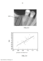
[030] A figura 3.1 é uma vista das amostras de osso de referência usados, após os implantes serem colocados.[030] Figure 3.1 is a view of the reference bone samples used, after the implants are placed.
[031] A figura 3.2 é uma imagem de raio-X de uma amostra de osso, sobre-posta pela região desenhada de interesse no local onde um implante será colocado.[031] Figure 3.2 is an X-ray image of a bone sample, overlaid by the region of interest drawn on the place where an implant will be placed.
[032] A figura 3.3 é uma imagem de raio-X da mandíbula de um paciente, sobreposta pela região desenhada de interesse no local onde o implante será colo-cado.[032] Figure 3.3 is an X-ray image of a patient's jaw, superimposed by the region of interest on the site where the implant will be placed.
[033] A figura 3.4 é um gráfico da correlação máxima entre o Quociente de Estabilidade de Implante e o Parâmetro de Textura de Osso.[033] Figure 3.4 is a graph of the maximum correlation between the Implant Stability Quotient and the Bone Texture Parameter.
[034] A tabela 3.5 é uma tabela mostrando para cada implante (ou a região correspondente de interesse em cada osso do maxilar) o valor computado para o Parâmetro de Textura de Osso para cada configuração e o ISQ.[034] Table 3.5 is a table showing for each implant (or the corresponding region of interest in each jaw bone) the value computed for the Bone Texture Parameter for each configuration and the ISQ.
[035] A tabela 3.6 exibe a correlação dos coeficientes entre o Parâmetro de Textura de Osso e o ISQ para cada configuração.[035] Table 3.6 shows the correlation of the coefficients between the Bone Texture Parameter and the ISQ for each configuration.
[036] A presente invenção refere-se a um método para determinar um indi-cador para a qualidade de um local de osso pretendido para receber um implante, e que é usado como um indicador para a estabilidade dos implantes que serão parafu-sados ou colados a ele. A modalidade preferida deste método é caracterizada pelo uso de uma tecnologia de imagem do local ósseo aceitador que pode fazer uso de uma análise quantitativa da variabilidade espacial dos níveis em cinza na imagem escaneada do local ósseo aceitador antes do carregamento do implante e o parafu- samento / colagem. Usando um software específico, a variabilidade espacial destas sombras em cinza pode ser diretamente correlacionada a textura do osso, que é um indicador forte da osseointegração do implante. A saída de uma metodologia de aná-lise consiste em uma representação de um variograma das medidas óticas digitali-zadas das sombras em cinza dentro da imagem, de forma que o indicador de estabi-lidade para uma dada área óssea aceitadora é avaliado pelo valor principal dos indi-cadores para esta área. Para cada pixel da imagem do local aceitador, a variabilidade dos pixels circundantes pode ser calculada como a soma das diferenças dos quadrados de duas sombras de intensidade cinza em uma dada distância do pixel de referência. Estas variações são então plotadas usando uma escala log-log.[036] The present invention relates to a method for determining an indicator for the quality of a bone site intended to receive an implant, and which is used as an indicator for the stability of the implants to be screwed or glued to it. The preferred modality of this method is characterized by the use of an acceptor bone site imaging technology that can make use of a quantitative analysis of the spatial variability of the gray levels in the scanned image of the acceptor bone site before the implant is loaded and screwed. / collage. Using specific software, the spatial variability of these gray shadows can be directly correlated to the texture of the bone, which is a strong indicator of implant osseointegration. The output of an analysis methodology consists of a representation of a variogram of the digitized optical measurements of the gray shadows within the image, so that the stability indicator for a given accepting bone area is evaluated by the main value indicators for this area. For each pixel in the image of the acceptor site, the variability of the surrounding pixels can be calculated as the sum of the differences of the squares of two shadows of gray intensity at a given distance from the reference pixel. These variations are then plotted using a log-log scale.
[037] Usando uma função matemática de um para um, a área de pixel que pode ser computadorizada é definida e o indicador de estabilidade é calculado como uma inclinação desta função.[037] Using a one-to-one mathematical function, the pixel area that can be computed is defined and the stability indicator is calculated as an inclination of this function.
[038] Primeiramente, uma imagem bidimensional ou tridimensional é propor-cionada de um osso 1.16, 2.16, 2.18 em uma localização onde um implante é plane-jado.[038] First, a two-dimensional or three-dimensional image is provided of a 1.16, 2.16, 2.18 bone in a location where an implant is planned.
[039] As imagens mencionadas aqui são produzidas, por exemplo, usando tecnologias de imagem por raio-X, em particular uma radiografia em raio-X digital, uma imagem por absorção de dois fótons, escaneadores padrão e escaneadores com feixe em cone.[039] The images mentioned here are produced, for example, using X-ray imaging technologies, in particular a digital X-ray radiography, a two-photon absorption image, standard scanners and cone beam scanners.
[040] Como mencionado, quando a imagem tridimensional é proporcionada de um osso em uma localização onde o implante ósseo 1.18, 2.12 é planejado, a imagem tridimensional é tanto projetada em um plano quanto é processada como uma imagem tridimensional para determinar o parâmetro da estrutura óssea.[040] As mentioned, when the three-dimensional image is provided of a bone at a location where the bone implant 1.18, 2.12 is planned, the three-dimensional image is either projected onto a plane or processed as a three-dimensional image to determine the structure parameter bone.
[041] Proporcionar imagens bidimensionais ou tridimensionais de raio-X dos ossos 1.16, 2.16, 2.18 com o propósito de um prognóstico é, por exemplo, descrita nas publicações de patente norte americanas US2008/0031412 A1, US1010/09998212 A1 e US 2011/0036360 A1.[041] Providing two-dimensional or three-dimensional X-ray images of bones 1.16, 2.16, 2.18 for the purpose of a prognosis is, for example, described in US patent publications US2008 / 0031412 A1, US1010 / 09998212 A1 and US 2011 / 0036360 A1.
[042] A imagem de raio-X digital usa técnicas diretas ou indiretas: ambas técnicas podem ser usadas em uma imagem de raio-X numérica.[042] The digital X-ray image uses direct or indirect techniques: both techniques can be used in a numerical X-ray image.
[043] De acordo com o método inventivo, o parâmetro de estrutura óssea em tal local onde o implante é planejado é derivado de uma imagem bidimensional ou tridimensional. O parâmetro de estrutura óssea é, por exemplo, representativo da estrutura de osso trabecular. O parâmetro de estrutura óssea pode, por exemplo, ser determinado pela análise da textura de uma imagem de escala em cinza bidimensio-nal ou tridimensional em uma região de interesse em tal local onde o implante ósseo 1.18, 2.12 é planejado.[043] According to the inventive method, the bone structure parameter in such a place where the implant is planned is derived from a two-dimensional or three-dimensional image. The bone structure parameter is, for example, representative of the trabecular bone structure. The bone structure parameter can, for example, be determined by analyzing the texture of a two-dimensional or three-dimensional gray scale image in a region of interest in such a location where the bone implant 1.18, 2.12 is planned.
[044] As sombras em cinza são definidas como etapas de luminosidade que diferem por uma quantidade definida dentro de uma imagem. A diferença mínima entre as duas sombras de cinza corresponde a etapa de quantificação da imagem. A proporção de contraste é definida como sendo o valor de luminosidade máxima divi-dido pelo valor de luminosidade mínimo, com a média dinâmica sendo o número de sombras em cinza entre o mínimo e o máximo.[044] Shadows in gray are defined as steps of luminosity that differ by a defined amount within an image. The minimum difference between the two shades of gray corresponds to the image quantification step. The contrast ratio is defined as the maximum brightness value divided by the minimum brightness value, with the dynamic average being the number of shadows in gray between the minimum and the maximum.
[045] Um método preferido de derivar um parâmetro de estrutura óssea é descrito no US Patent 7,609,867, resumido como as seguintes etapas realizadas pelo dispositivo de computação configurado para processar uma imagem bidimensional ou tridimensional digitalizada: a) recuperar um nível em cinza h(O) para cada pixel em uma região de inte-resse da imagem bidimensional ou tridimensional; b) selecionar um conjunto representativo de pixels em uma distância r ao re-dor de h(O); c) recuperar o nível em cinza h(r) de tal conjunto de pixels; d) computar uma variância V(r) de níveis em cinza com a fórmula: V(r) = [h(r) - h(O)]2; e) traçar uma curva associada ao V(r) em uma escala log-log; e f) determinar o declínio da curva de tal parâmetro de estrutura óssea.[045] A preferred method of deriving a bone structure parameter is described in US Patent 7,609,867, summarized as the following steps performed by the computing device configured to process a digitized two-dimensional or three-dimensional image: a) recover a gray level h (O ) for each pixel in a region of interest of the two-dimensional or three-dimensional image; b) select a representative set of pixels at a distance r to the remainder of h (O); c) recover the gray level h (r) of such a set of pixels; d) compute a variance V (r) of levels in gray with the formula: V (r) = [h (r) - h (O)] 2; e) plot a curve associated with V (r) on a log-log scale; and f) determine the decline in the curve of such bone structure parameter.
[046] Nas etapas a) a f), um número de escolhas técnicas pode ser feito para a computação e mudará o valor do parâmetro de estrutura óssea. Parte de nosso método inventivo consiste em ajustar estas escolhas a fim de maximizar a correlação entre o parâmetro de estrutura óssea e a estabilidade do implante.[046] In steps a) to f), a number of technical choices can be made for the computation and will change the value of the bone structure parameter. Part of our inventive method is to adjust these choices in order to maximize the correlation between the bone structure parameter and implant stability.
[047] Outro método de derivação do parâmetro de estrutura óssea, descrito no FR2960762 A1, é com base na seleção de uma região de área de interesse em uma imagem de nível em cinza de um tecido ósseo, calcular o nível em cinza e comparar este com um limite limiar. Um valor de um parâmetro de emissão é deter-minado de acordo com o valor dos níveis em cinza e o limiar. Uma imagem é adqui-rida usando um aparelho de imagem proporcionado com um novo valor do parâmetro de emissão.[047] Another method of deriving the bone structure parameter, described in FR2960762 A1, is based on selecting a region of area of interest in a gray level image of a bone tissue, calculating the gray level and comparing this with a threshold threshold. A value of an emission parameter is determined according to the value of the gray levels and the threshold. An image is acquired using an imaging device provided with a new emission parameter value.
[048] O método inventivo compreende proporcionar dados de estabilidade do implante que sejam relacionados aos dados representando o parâmetro de estrutura óssea.[048] The inventive method comprises providing implant stability data that are related to the data representing the bone structure parameter.
[049] Os dados de estabilidade de implante são coletados usando as amos-tras de osso (ex-vivo, a partir de um cadáver humano ou in-vivo, a partir de ossos do paciente) e um conjunto de implantes de referência; os implantes de referência são implantados em tais amostras de osso e a estabilidade dos implantes é avaliada usando um metro de estabilidade de implante que calcula o RFA de todos os implan-tes implantados. A estabilidade do implante é gravada imediatamente após a implan-tação (estabilidade primária) e/ou após o período de osseointegração (estabilidade secundária, apenas para os ossos in-vivo).[049] Implant stability data are collected using bone samples (ex-vivo, from a human cadaver or in-vivo, from the patient's bones) and a set of reference implants; the reference implants are implanted in such bone samples and the stability of the implants is assessed using an implant stability meter that calculates the RFA of all implanted implants. The implant stability is recorded immediately after implantation (primary stability) and / or after the osseointegration period (secondary stability, only for in-vivo bones).
[050] As imagens bidimensionais ou tridimensionais de tais amostras de osso são adquiridas e o parâmetro de estrutura óssea é computado a partir de tais ima- gens, com várias variáveis.[050] Two-dimensional or three-dimensional images of such bone samples are acquired and the bone structure parameter is computed from such images, with several variables.
[051] Os dados de estabilidade de implante são usados para selecionar as variáveis apropriadas. As variáveis selecionadas são aquelas que maximizam a cor-relação entre o parâmetro de estrutura óssea e o RFA. Várias configurações de vari-áveis são definidas: uma usando os dados de estabilidade primária para otimizar o parâmetro de estrutura óssea como um indicador da estabilidade primária do implan-te; outro usando os dados de estabilidade secundária para otimizar o parâmetro de estrutura óssea como um indicador da estabilidade secundária do implante. As con-figurações adicionais de variáveis podem ser usadas para otimizar o parâmetro de estrutura óssea como um indicador da estabilidade do implante em diferentes tipos de ossos: mandíbula, maxilar, quadril, fêmur 2.16, joelho, tíbia 2.18, ombro, etc. As configurações adicionais das variáveis podem ser usadas para otimizar o parâmetro de estrutura óssea como um indicador da estabilidade do implante de diferentes ti-pos de implantes: implantes de dentes com várias formas; implantes ortopédicos que podem ser pinos, hastes, parafusos ou placas; ossos substitutos (neste caso, o pa-râmetro de estrutura óssea é um indicador da osseointegração do implante).[051] Implant stability data is used to select the appropriate variables. The selected variables are those that maximize the color-relationship between the bone structure parameter and the RFA. Several variable configurations are defined: one using the primary stability data to optimize the bone structure parameter as an indicator of the implant's primary stability; another using secondary stability data to optimize the bone structure parameter as an indicator of secondary implant stability. Additional variable settings can be used to optimize the bone structure parameter as an indicator of implant stability in different types of bones: mandible, maxilla, hip, femur 2.16, knee, tibia 2.18, shoulder, etc. Additional variable settings can be used to optimize the bone structure parameter as an indicator of implant stability for different types of implants: tooth implants with various shapes; orthopedic implants that can be pins, nails, screws or plates; substitute bones (in this case, the bone structure parameter is an indicator of implant osseointegration).
[052] O método inventivo proporciona para determinar, a partir de um parâ-metro de estrutura óssea determinado e a partir de tais dados de estabilidade de implante, um indicador para a estabilidade do implante ósseo 1.18, 2.12 planejado após a implantação em tal local.[052] The inventive method provides to determine, from a determined bone structure parameter and from such implant stability data, an indicator for bone implant stability 1.18, 2.12 planned after implantation in such a location .
[053] Uma imagem bidimensional ou tridimensional do osso que pretende re-ceber um ou mais implantes é adquirida. O parâmetro de estrutura óssea é compu-tado a partir de tal imagem usando as variáveis otimizadas para a determinação de uma estabilidade primária (reciprocamente da estabilidade secundária). EXEMPLO 1 - IMPLANTE DE DENTE[053] A two-dimensional or three-dimensional image of the bone that intends to receive one or more implants is acquired. The bone structure parameter is computed from such an image using the variables optimized for the determination of primary stability (conversely of secondary stability). EXAMPLE 1 - TOOTH IMPLANT
[054] A figura 1 mostra, por meio de exemplo, uma vista em corte de um im-plante de dente 18 inserido no osso da mandíbula 1.16. O osso da mandíbula 1.16 é feito de um osso trabecular. A qualidade do osso trabecular é uma chave determi-nante de uma boa osseointegração do implante. Como mostrado, o dente tem uma coroa 1.10 acima da raiz do dente 1.12 que passa através da gengiva 1.14 e se es-tende para baixo dentro do osso da mandíbula 1.16. O dente incorpora um implante 1.18 na forma de um parafuso feito de um material inerte, preferencialmente titânio.[054] Figure 1 shows, by way of example, a cross-sectional view of a
[055] Antes do implante ser encaixado, uma imagem de raio-X é tirada da região do osso da mandíbula onde o implante 1.18 é colocado. Esta imagem de raio- X é analisada para determinar um parâmetro de estrutura óssea representando uma estrutura óssea trabecular, por uma análise de textura de uma imagem de nível em cinza bidimensional ou tridimensional em uma região de interesse em tal local onde o implante de osso é planejado. Preferencialmente esta análise é realizada usando o método acima mencionado descrito no US Patent 7,609,867. Este parâmetro de es-trutura óssea é comparado com um conjunto de valores predeterminados a partir da configuração dos implantes de referência, como descrito acima em “Dados de Esta-bilidade do Implante”, usando também as variáveis selecionadas a partir dos tipos de ossos comparáveis, denominado mandíbula ou maxilar.[055] Before the implant is fitted, an X-ray image is taken from the region of the jaw bone where the 1.18 implant is placed. This X-ray image is analyzed to determine a bone structure parameter representing a trabecular bone structure, by a texture analysis of a two-dimensional or three-dimensional gray level image in a region of interest at such a location where the bone implant is. planned. Preferably this analysis is performed using the aforementioned method described in US Patent 7,609,867. This bone structure parameter is compared with a set of predetermined values from the configuration of the reference implants, as described above in “Implant Stability Data”, also using the variables selected from the comparable bone types. , called the mandible or maxilla.
[056] O cálculo resultante leva a valores prevendo se o implante planejado será estável para sua estabilidade primária e secundária. Se os resultados mostrarem que o implante deve ser estável, o cirurgião dentista pode realizar o implante e reduzir o atraso antes do carregamento. Se o resultado mostrar que o implante pla-nejado seria instável, o cirurgião dentista pode tomar quaisquer medidas necessá-rias.[056] The resulting calculation leads to values predicting whether the planned implant will be stable for its primary and secondary stability. If the results show that the implant must be stable, the dental surgeon can perform the implant and reduce the delay before loading. If the result shows that the planned implant would be unstable, the dental surgeon can take any necessary measures.
[057] Após a implantação, a estabilidade primária e secundária pode ser checada pelas medidas RFA e comparadas com os valores previstos. EXEMPLO 2 - IMPLANTE ORTOPÉDICO[057] After implantation, primary and secondary stability can be checked by the RFA measures and compared with the predicted values. EXAMPLE 2 - ORTHOPEDIC IMPLANT
[058] A figura 2 mostra, por meio de exemplo, uma vista do raio-X de um im-plante de joelho ortopédico 2.12 inserido no fêmur (osso da coxa) 2.16 e uma tíbia (osso da tíbia) 2.18. O fêmur 2.16 e a tíbia 2.18 são feitos de um osso cortical e de um osso trabecular. A qualidade do osso trabecular é uma chave determinante de uma boa osseointegração do implante. Como mostrado, o implante é inserido nos ossos do fêmur e da tíbia, principalmente em sua parte trabecular uma vez que este é a superfície de contato implanto ao osso no osso trabecular (o osso que tem uma taxa maior de remodelação) que é uma chave determinante de uma boa osseointe- gração.[058] Figure 2 shows, by way of example, an X-ray view of an orthopedic knee implant 2.12 inserted in the femur (thigh bone) 2.16 and a tibia (tibia bone) 2.18. The femur 2.16 and the tibia 2.18 are made of a cortical bone and a trabecular bone. The quality of the trabecular bone is a key determinant of good implant osseointegration. As shown, the implant is inserted into the bones of the femur and tibia, mainly in its trabecular part since this is the contact surface implant to the bone in the trabecular bone (the bone that has a higher remodeling rate) which is a key determinant of good osseointegration.
[059] Antes do implante ser encaixado, uma imagem de raio-X é tirada da região do osso do joelho onde o implante 2.12 é colocado. Esta imagem de raio-X é analisada para determinar um parâmetro de estrutura óssea representando uma es-trutura óssea trabecular, por uma análise de textura de uma imagem de nível em cinza bidimensional ou tridimensional em uma região de interesse em tal local onde o implante de osso é planejado. Preferencialmente esta análise é realizada usando o método acima mencionado descrito no US Patent 7,609,867. Este parâmetro de es-trutura óssea é comparado com um conjunto de valores predeterminados a partir da configuração dos implantes de referência, como descrito acima em “Dados de Esta-bilidade do Implante”, usando também as variáveis selecionadas a partir dos tipos de ossos comparáveis, denominado joelho.[059] Before the implant is fitted, an X-ray image is taken of the knee bone region where the 2.12 implant is placed. This X-ray image is analyzed to determine a bone structure parameter representing a trabecular bone structure, by analyzing the texture of a two-dimensional or three-dimensional gray level image in a region of interest in such a location where the implant of bone is planned. Preferably this analysis is performed using the aforementioned method described in US Patent 7,609,867. This bone structure parameter is compared with a set of predetermined values from the configuration of the reference implants, as described above in “Implant Stability Data”, also using the variables selected from the comparable bone types. , called knee.
[060] O cálculo resultante leva a valores prevendo se o implante planejado será estável para sua estabilidade primária e secundária. Se os resultados mostrarem que o implante deve ser estável, o cirurgião ortopedista pode realizar o implante e reduzir o atraso antes de restaurar a função. Se o resultado mostrar que o implante planejado seria instável, o cirurgião ortopedista pode tomar quaisquer medidas ne-cessárias. EXEMPLO 3 - ESTABILIDADE PRIMÁRIA DE UM IMPLANTE DE DENTE NA MANDÍBULA POSTERIOR[060] The resulting calculation leads to values predicting whether the planned implant will be stable for its primary and secondary stability. If the results show that the implant must be stable, the orthopedic surgeon can perform the implant and reduce the delay before restoring function. If the result shows that the planned implant would be unstable, the orthopedic surgeon can take any necessary measures. EXAMPLE 3 - PRIMARY STABILITY OF A TOOTH IMPLANT IN THE BACK MANDIBLE
[061] Usando um conjunto de amostras de osso desdentado (figura 3.1, A), denominada mandíbulas, os locais são definidos onde os implantes serão coloca-dos, denominado na mandíbula posterior. As imagens das amostras de osso são tomadas, por exemplo, imagens de raio-X periapicais usando protocolos de imagem padrão (figura 3.2) para cada imagem resultante, uma ou várias regiões de interesse são desenhadas sobre o osso onde o implante será colocado (figura 3.2, A). Então as análises das texturas são realizadas, preferencialmente usando o método acima mencionado descrito na Patent 7,609,867. Para cada região de interesse, o parâme-tro de estrutura óssea é computado usando várias configurações Ci (tabela 3.5).[061] Using a set of toothless bone samples (figure 3.1, A), called mandibles, the locations are defined where the implants will be placed, called the posterior mandible. The images of the bone samples are taken, for example, periapical X-ray images using standard imaging protocols (figure 3.2) for each resulting image, one or more regions of interest are drawn on the bone where the implant will be placed (figure 3.2, A). Then the analysis of the textures is carried out, preferably using the method mentioned above described in Patent 7,609,867. For each region of interest, the bone structure parameter is computed using various Ci configurations (table 3.5).
[062] Usando o mesmo conjunto de amostras de osso, os implantes de dente de referência são colocados nos locais definidos anteriormente (figura 3.1,B). A es-tabilidade dos implantes é medida usando a análise de frequência de referência com um dispositivo Osstell e os Quocientes de Estabilidade de Implantes (ISQ) são de-terminados (tabela 3.5).[062] Using the same set of bone samples, the reference tooth implants are placed in the previously defined locations (figure 3.1, B). The stability of the implants is measured using the reference frequency analysis with an Osstell device and the Implant Stability Quotients (ISQ) are determined (table 3.5).
[063] Para cada região de interesse e para cada configuração da análise de textura, a correlação entre ISQ e o parâmetro de estrutura óssea é determinado (ta-bela 3.6).[063] For each region of interest and for each texture analysis configuration, the correlation between ISQ and the bone structure parameter is determined (table 3.6).
[064] Por fim, o máximo da correlação é determinado (tabela 3.6, C1, e a figu-ra 3.4) e a configuração correspondente da análise de textura é armazenada. Esta configuração C1 é específica para avaliação da estabilidade primária dos implantes de dente na mandíbula posterior usando este tipo de dispositivo de imagem médica.[064] Finally, the maximum of the correlation is determined (table 3.6, C1, and figure 3.4) and the corresponding configuration of the texture analysis is stored. This C1 configuration is specific for assessing the primary stability of tooth implants in the posterior mandible using this type of medical imaging device.
[065] Usando uma imagem de raio-X de um osso de paciente onde um im-plante é planejado (figura 3.3), denominado mandíbula posterior, uma região de inte-resse é desenhada na imagem do osso onde o implante é para ser colocado (figura 3.3, A). A análise de textura é computada usando uma configuração C1. O valor re-sultante permite prever se o implante planejado será estável imediatamente após a colocação (estabilidade primária. Se os resultados mostrarem que o implante deveria ser estável, o cirurgião dentista pode realizar o implante e, por exemplo, reduzir o atraso antes do carregamento. Se o resultado mostrar que o implante planejado seria instável, o cirurgião dentista pode tomar quaisquer medidas necessárias. EXEMPLO - ESTABILIDADE PRIMÁRIA DE UM IMPLANTE ORTOPÉDICO NA ESPINHA[065] Using an X-ray image of a patient's bone where an implant is planned (figure 3.3), called the posterior mandible, a region of interest is drawn on the image of the bone where the implant is to be placed (figure 3.3, A). Texture analysis is computed using a C1 configuration. The resulting value allows to predict whether the planned implant will be stable immediately after placement (primary stability. If the results show that the implant should be stable, the dental surgeon can perform the implant and, for example, reduce the delay before loading If the result shows that the planned implant would be unstable, the dental surgeon can take any necessary measures EXAMPLE - PRIMARY STABILITY OF AN ORTHOPEDIC IMPLANT IN THE SPINE
[066] Usando um conjunto de amostras, por exemplo, amostras de espinha as imagens de raio-X planas são tomadas (figura 4), usando protocolos de imagem padrão. Para cada imagem resultante, uma ou várias regiões de interesse são dese-nhadas sobre o osso onde o implante será colocado (figura 4, A). Então as análises das texturas são realizadas, preferencialmente usando o método acima mencionado descrito na Patent 7,609,867. Para cada região de interesse, o parâmetro de estrutura óssea é computado usando várias configurações Ci.[066] Using a sample set, for example, spine samples the flat X-ray images are taken (figure 4), using standard imaging protocols. For each resulting image, one or more regions of interest are drawn on the bone where the implant will be placed (figure 4, A). Then the analysis of the textures is carried out, preferably using the method mentioned above described in Patent 7,609,867. For each region of interest, the bone structure parameter is computed using various Ci configurations.
[067] Usando o mesmo conjunto de amostras de osso, os implantes de espi-nha são colocados nos locais definidos anteriormente. A estabilidade dos implantes é então medida usando a força necessária para arrancar os implantes a partir das amostras de osso.[067] Using the same set of bone samples, the spine implants are placed in the previously defined locations. The stability of the implants is then measured using the force necessary to pull the implants out of the bone samples.
[068] Para cada região de interesse e para cada configuração da análise de textura, a correlação entre a força de arranque e o parâmetro de estrutura óssea é determinado.[068] For each region of interest and for each texture analysis setting, the correlation between the pullout force and the bone structure parameter is determined.
[069] Por fim, o máximo da correlação é determinado e a configuração cor-respondente da análise de textura é armazenada. Esta configuração Ca é específica para avaliação da estabilidade primária dos implantes deste tipo de implantes de espinha usando este tipo de dispositivo de imagem médica.[069] Finally, the maximum of the correlation is determined and the corresponding configuration of the texture analysis is stored. This Ca configuration is specific for evaluating the primary stability of implants of this type of spine implants using this type of medical imaging device.
[070] Usando uma imagem de raio-X da espinha do paciente onde um im-plante é planejado, uma região de interesse é desenhada na imagem do osso onde o implante é para ser colocado. A análise de textura é computada usando uma con- figuração Ca. O valor resultante permite prever se o implante planejado será estável imediatamente após a colocação (estabilidade primária).[070] Using an X-ray image of the patient's spine where an implant is planned, a region of interest is drawn on the image of the bone where the implant is to be placed. The texture analysis is computed using a Ca configuration. The resulting value allows to predict whether the planned implant will be stable immediately after placement (primary stability).
Claims (9)
Applications Claiming Priority (3)
| Application Number | Priority Date | Filing Date | Title |
|---|---|---|---|
| IB2013052171 | 2013-03-19 | ||
| IBPCT/2013/052171 | 2013-03-19 | ||
| PCT/IB2014/059963 WO2014147566A1 (en) | 2013-03-19 | 2014-03-19 | A method of determining an indicator for the stability of a bone implant |
Publications (2)
| Publication Number | Publication Date |
|---|---|
| BR112015024160A2 BR112015024160A2 (en) | 2017-07-18 |
| BR112015024160B1 true BR112015024160B1 (en) | 2021-03-16 |
Family
ID=50736121
Family Applications (1)
| Application Number | Title | Priority Date | Filing Date |
|---|---|---|---|
| BR112015024160-3A BR112015024160B1 (en) | 2013-03-19 | 2014-03-19 | computer-implemented method to determine an indicator for the stability of a bone implant |
Country Status (5)
| Country | Link |
|---|---|
| US (1) | US10032269B2 (en) |
| EP (1) | EP2976039B1 (en) |
| BR (1) | BR112015024160B1 (en) |
| ES (1) | ES2828668T3 (en) |
| WO (1) | WO2014147566A1 (en) |
Families Citing this family (3)
| Publication number | Priority date | Publication date | Assignee | Title |
|---|---|---|---|---|
| WO2021059668A1 (en) * | 2019-09-27 | 2021-04-01 | 富士フイルム株式会社 | Information processing device, information processing method, and program |
| WO2023051909A1 (en) * | 2021-09-29 | 2023-04-06 | Medimaps Group Sa | Process and device for analyzing a texture of a tissue |
| CN113855291B (en) * | 2021-12-01 | 2022-02-22 | 极限人工智能有限公司 | Implant auxiliary planning method and device, electronic equipment and storage medium |
Family Cites Families (9)
| Publication number | Priority date | Publication date | Assignee | Title |
|---|---|---|---|---|
| SE516917C2 (en) * | 1997-11-11 | 2002-03-19 | Nobel Biocare Ab | Device for providing reliable anchoring of threaded implants in bone |
| US6904123B2 (en) | 2000-08-29 | 2005-06-07 | Imaging Therapeutics, Inc. | Methods and devices for quantitative analysis of x-ray images |
| US8639009B2 (en) | 2000-10-11 | 2014-01-28 | Imatx, Inc. | Methods and devices for evaluating and treating a bone condition based on x-ray image analysis |
| FR2848694B1 (en) | 2002-12-17 | 2005-06-10 | Laurent Pothuaud | METHOD FOR DETERMINING A 3D STRUCTURE FROM A 2D IMAGE, IN PARTICULAR THE STRUCTURE OF A BONE |
| US8290564B2 (en) | 2003-09-19 | 2012-10-16 | Imatx, Inc. | Method for bone structure prognosis and simulated bone remodeling |
| GB0514554D0 (en) * | 2005-07-15 | 2005-08-24 | Materialise Nv | Method for (semi-) automatic dental implant planning |
| US8206153B2 (en) * | 2007-05-18 | 2012-06-26 | Biomet 3I, Inc. | Method for selecting implant components |
| EP2143451A1 (en) * | 2008-07-11 | 2010-01-13 | Nobel Biocare Services AG | Bone implant application |
| FR2960762B1 (en) | 2010-06-07 | 2013-04-05 | Designers Developers Distributors Associates D3A Medical Systems | METHODS AND SYSTEMS FOR IMAGING AND CHARACTERIZING BONE TISSUE |
-
2014
- 2014-03-19 BR BR112015024160-3A patent/BR112015024160B1/en not_active IP Right Cessation
- 2014-03-19 ES ES14725242T patent/ES2828668T3/en active Active
- 2014-03-19 US US14/775,903 patent/US10032269B2/en active Active
- 2014-03-19 EP EP14725242.3A patent/EP2976039B1/en active Active
- 2014-03-19 WO PCT/IB2014/059963 patent/WO2014147566A1/en not_active Ceased
Also Published As
| Publication number | Publication date |
|---|---|
| EP2976039A1 (en) | 2016-01-27 |
| BR112015024160A2 (en) | 2017-07-18 |
| US20160035089A1 (en) | 2016-02-04 |
| WO2014147566A1 (en) | 2014-09-25 |
| US10032269B2 (en) | 2018-07-24 |
| EP2976039B1 (en) | 2020-08-19 |
| ES2828668T3 (en) | 2021-05-27 |
Similar Documents
| Publication | Publication Date | Title |
|---|---|---|
| Fuster-Torres et al. | Relationships between bone density values from cone beam computed tomography, maximum insertion torque, and resonance frequency analysis at implant placement: a pilot study. | |
| Ribeiro‐Rotta et al. | Bone tissue microarchitectural characteristics at dental implant sites part 2: correlation with bone classification and primary stability | |
| Sim et al. | Factors influencing resonance frequency analysis assessed by Osstell™ mentor during implant tissue integration: I. Instrument positioning, bone structure, implant length | |
| Turkyilmaz et al. | Biomechanical aspects of primary implant stability: a human cadaver study | |
| García‐García et al. | Accuracy of periapical radiography in assessing bone level in implants affected by peri‐implantitis: a cross‐sectional study | |
| Wakimoto et al. | Bone quality and quantity of the anterior maxillary trabecular bone in dental implant sites | |
| Turkyilmaz et al. | Determination of bone quality of 372 implant recipient sites using Hounsfield unit from computerized tomography: a clinical study | |
| Salimov et al. | Evaluation of relationship between preoperative bone density values derived from cone beam computed tomography and implant stability parameters: a clinical study | |
| Turkyilmaz et al. | Influence of bone density on implant stability parameters and implant success: a retrospective clinical study | |
| Molly | Bone density and primary stability in implant therapy | |
| Merheb et al. | Relationship between cortical bone thickness or computerized tomography‐derived bone density values and implant stability | |
| Gomes de Oliveira et al. | Bone tissue microarchitectural characteristics at dental implant sites. Part 1: Identification of clinical‐related parameters | |
| Monje et al. | Maxillary sinus lateral wall thickness and morphologic patterns in the atrophic posterior maxilla | |
| YANG et al. | Computed tomographic assessment of maxillary sinus wall thickness in edentulous patients | |
| Liu et al. | Efficacy of cone-beam computed tomography in evaluating bone quality for optimum implant treatment planning | |
| Suttapreyasri et al. | The accuracy of cone-beam computed tomography for evaluating bone density and cortical bone thickness at the implant site: micro-computed tomography and histologic analysis | |
| Shiffler et al. | Effect of length, diameter, intraoral location on implant stability | |
| Chow et al. | Bone stability around implants in elderly patients with reduced bone mineral density–a prospective study on mandibular overdentures | |
| Chugh et al. | Use of digital panoramic radiology in presurgical implant treatment planning to accurately assess bone density | |
| Tözüm et al. | Radiographic fractal and clinical resonance frequency analyses of posterior mandibular dental implants: their possible association with mandibular cortical index with 12-month follow-up | |
| Al-Gunaid | Sex-related variation in the dimensions of the mandibular ramus and its relationship with lower third molar impaction | |
| KR20100063909A (en) | Method and support device for jawbone mineral density measurement | |
| Monje et al. | Microarchitectural pattern of pristine maxillary bone. | |
| BR112015024160B1 (en) | computer-implemented method to determine an indicator for the stability of a bone implant | |
| Oliveira et al. | The correlation of different methods for the assessment of bone quality in vivo: an observational study |
Legal Events
| Date | Code | Title | Description |
|---|---|---|---|
| B06F | Objections, documents and/or translations needed after an examination request according [chapter 6.6 patent gazette] | ||
| B06U | Preliminary requirement: requests with searches performed by other patent offices: procedure suspended [chapter 6.21 patent gazette] | ||
| B06A | Patent application procedure suspended [chapter 6.1 patent gazette] | ||
| B09A | Decision: intention to grant [chapter 9.1 patent gazette] | ||
| B16A | Patent or certificate of addition of invention granted [chapter 16.1 patent gazette] |
Free format text: PRAZO DE VALIDADE: 20 (VINTE) ANOS CONTADOS A PARTIR DE 19/03/2014, OBSERVADAS AS CONDICOES LEGAIS. |
|
| B21F | Lapse acc. art. 78, item iv - on non-payment of the annual fees in time |
Free format text: REFERENTE A 12A ANUIDADE. |