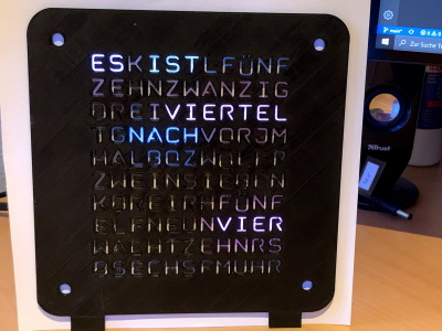
An ESP8266 based Word Clock built with PlatformIO that fetches the time from a NTP server.
This is firmware for the 11x10 LED Matrix word clock case from WordClock 12h (desk clock edition) from Thingiverse. It features MQTT autodiscovery for Home Assistant
It currently has three modes:
- word clock with seconds as ambilight
- rainbow animation
- aurora borealis animation
The modes and brightness can be set via mqtt by writing to the following mqtt topics:
wordclock/brightness/set(0..255) - very low brighness values (e.g. less than 20) may lead to colors not being shown properlywordclock/mode/set(0..2)
When the word clock is powered up, it starts in mode 0 (word clock) with brightness 20. The word clock reports its state via the following mqtt topics:
wordclock/$localip- the ip address assigned to the word clodkwordclock/$mac- the mac address of the ESP8266wordclock/$state- (ready|lost).readywhen connected to wifi and mqtt. The state switches tolostautomatically, when the connection is lost.wordclock/brightness- the current brightnesswordclock/mode- the current mode
Dependencies are:
- FastLed
- NtpClient
- Time
- TimeZone
- espMqttClient
- HaMqttConfigBuilder
If you build the firmware using PlatformIO, all dependencies are pulled in automatically. If you prefer a different IDE you have to take care of everything yourself.
The wifi and mqtt credentials are stored in an external "secrets.h" file.
 |
 |
|---|---|
| Open case | Open case |
The pictures below are taken with almost minimal brightness of the LEDs.
 |
 |
 |
|---|---|---|
| No diffusor | A sheet of paper as diffusor | Paper and front |
The case is beautiful, but IMHO it has two drawbacks:
- The grid part for the LEDs should be printed separately in black. Even though I have spray painted the inner walls of the grid white twice, there's still a glow effect from one chamber to the next.
- Another reason for the glow effect is probably that it is not possible to bring the LEDs 100% tight to the grid. The cables that you have to solder to the ends and the LED strip itself will always account for a 1mm gap between LEDs and grid, so light can get through. This can perhaps be solved by filing down the vertical parts of the grid a bit, but it would be better to make the horizontal parts of the grid a bit longer on the rear side.


