|
|
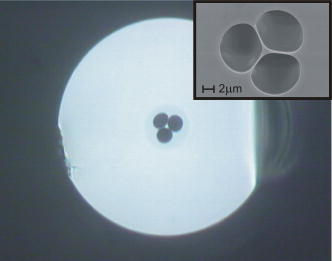
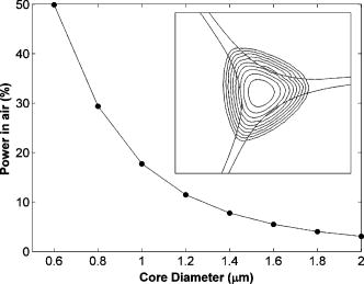
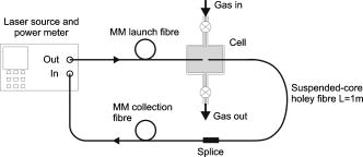
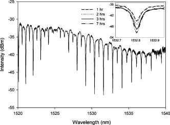
1.IntroductionIndex-guiding microstructured fibers (MFs) or holey fibers (HFs) consist of a solid central core surrounded by an array of air holes that run longitudinally along the length of the fiber. The light is guided by the effective index contrast between the core and the cladding. The placement of these holes fundamentally influences the guidance in the fiber, and a strong wavelength dependence of the cladding refractive index enables unique properties to be realized. These include endlessly single-mode operation1 and high nonlinearity.2 These guidance properties are generally not possible with conventional solid fiber, and this has led to the widespread interest in holey fibers. Embedded in the mechanism by which index guiding holey fibers operate is the interaction between the core mode and surrounding medium. It has been proposed that the evanescent field could be used for the sensing of gases and liquids within the holes of the fiber.3 Providing that the core mode substantially extends into the air holes, such fibers would be suitable for sensing a range of gases and offer a high sensitivity due to the potential for long interaction lengths. This concept has given rise to numerous reported fiber designs for the sensing of trace elements in gases and liquids.4, 5, 6, 7 The most common preform fabrication process used for complex microstructured fibers is referred to as the stacking technique. This involves manufacturing hundreds of hollow capillaries on a fiber drawing tower, which are then stacked in a hexagonal arrangement inside a jacket tube. The dimension of the capillaries used determines the pitch and hole diameter of the fiber lattice, and thus its specific optical properties. Depending on the required scale-down ratio, this preform is then either drawn directly into fiber or caned and redrawn inside another jacket tube to further scale down the features.8 Although stacking offers a diverse fabrication route, it is a laborious process often taking weeks to produce a single preform. There are also inherent difficulties in drawing preforms with such complex profiles into fiber as a unique understanding of the pressure effects inside the holes is needed to achieve the desired results. A common alternative for preform fabrication is to use ultrasonic drilling to define the holes.9 This provides a straightforward approach but is mainly reserved for structures with a small number of holes. In this paper, we describe a fabrication process for producing a suspended-core holey fiber structure that is ideally suited to sensing applications. The suspended-core structure was proposed by Monro 3 and approaches that of a jacketed air-suspended rod (JASR). The JASR is impractical but it represents the theoretical limit for the highest possible air-filling fraction.10 A suspended-core fiber structure has been demonstrated in bismuth glass using an extrusion technique,11, 12 but to our knowledge, not in silica. The fabrication process reported here uses ultrasonic drilling to define the air holes in a solid silica rod, which is then caned and drawn inside a jacket tube into fiber, using a conventional fiber-drawing tower. The crucial step is to manipulate the shape of the holes during the draw to produce a final geometry of a small core supported by three fine struts. The holey fiber reported has a much higher proportion of light propagating in the air compared to other previously reported index-guiding designs, and is significantly higher than demonstrated by Hoo 5 To demonstrate the suspended-core holey fiber as an evanescent-field device a simple gas sensor is constructed using acetylene as the sensing medium due to its strong absorption lines in the wavelength range 1520 to . Futhermore, it is proposed that the fiber is appropriate for sensing a wide range of gases within the transmission window of silica. 2.Experiment and ResultsThe fiber preform was formed by defining three holes in a silica rod (Heralux HLQ210) using in-house ultrasonic glass-drilling equipment. The centers of the holes formed an equilateral triangle with a solid section of glass left between adjacent holes. The glass was then caned to a diameter of approximately on a standard fiber-drawing tower using a furnace temperature that was sufficiently low to retain the internal geometry. A length of the cane was then inserted into a silica cladding tube. The tube dimensions were chosen so that a large air gap was left around the cane. This enabled the shape of the holes to be manipulated during the draw by applying a vacuum around the cane, which introduces a pressure differential between the holes inside the cane and the surrounding air space. Thus, the holes could be expanded and the strut length increased. It was found that the absolute differential pressure was not critical, providing that the cladding tube wall was comparably thicker than the cane diameter and the furnace temperature was sufficiently low. Using this principle, the fiber structure was tailored to give a small solid core suspended by three fine struts, as shown in Fig. 1. A range of fibers was subsequently drawn from the same cane material but using cladding tubes of various dimensions. Figure 1 shows the cross section of a diameter fiber with internal dimensions of 1.2, 8, and for the core diameter, hole diameter, and strut thickness, respectively. The core diameter quoted is defined as the largest diameter circle that fills the solid center region, while the hole diameter is the mean diameter irrespective of any ellipticity. Fibers with core diameters ranging from 0.8 to , and nominally outer diameter, were fabricated. In each case, several tens of meters of coated fiber was drawn with SEM analysis confirming that there was no observable change in structure along the length. The background loss of a fiber with a core diameter was measured as at using a white light source and a standard cutback method. The relatively high loss is mainly attributed to scattering due to the surface roughness of the holes following the ultrasonic drilling. No attempt was made to improve on the surface roughness in this case, however, preliminary investigation suggests that the loss can be substantially reduced with gas-phase chemical etching of the holes prior to caning. A high absorption peak of more than was seen in the fiber at a wavelength of , which corresponds to water contamination. Although surface OH is a known problem with holey fiber, a drying stage during the glass preparation as well as using a higher purity silica starting rod will most probably reduce this value. Numerical simulation was performed on the measured fiber cross section using a full vector finite element method (FEM) to assess the fraction of light propagating in the air cladding. The outline of the fiber profile was taken from an SEM image. Anisotropic perfectly matched layers were employed to reduce the simulation area, and a very dense mesh, consisting of more than 15,000 triangular elements in the core region alone, was used to ensure a good accuracy of the results. For fiber with a core diameter of , the core mode overlap was calculated as at . This number increases significantly to over for fiber with a smaller core diameter of . Figure 2 shows the calculated mode profile for a fiber with a core diameter as well as the relationship between core diameter and the percentage of power located in the holes. To demonstrate the use of the fiber as an evanescent field device a simple gas detection system was constructed using the apparatus shown in Fig. 3. A gas cell was made in-house which allowed the alignment of two fibers, while maintaining a small gap between them. This separation enabled the sample gas introduced into the cell to enter the holes in the fiber. For the experiments we used an Agilent Lightwave System (8164A) that incorporated a tuneable laser module and a power meter (HP 81531A), usable over the wavelength range of 1500 to . The system controlled and scanned the laser in steps, and collected the data from the power meter. The output from the tuneable laser was delivered through standard multimode (MM) fiber, which was in turn free-space coupled to a 1-m length of core diameter suspended-core holey fiber within the cell. The separation between the fibers was approximately and MM fiber was used in this case to facilitate the alignment process and maximize the transmitted power. The other end of the holey fiber was spliced to the collection fiber and again standard MM fiber was used. This was then attached to the power meter. To fill the fiber a flow of acetylene was passed through the chamber, orthogonal to the fiber face, at a rate of . After , the chamber was sealed. The flow rate and loading time were chosen to be sufficiently high to ensure that all air was removed from the cell. As the other end of the fiber was sealed, filling of the holes with acetylene relied solely on diffusion and thus a significant length of time was required to completely fill the fiber with the sample gas. The tuneable laser was scanned between the wavelengths 1520 and with a resolution of . The data from the power meter was recorded and stored. The scan was repeated at hourly intervals. The acetylene absorption lines increased over time as the acetylene diffused along the length of the fiber. No further change in absorption was seen after . The resulting spectrum can be seen in Fig. 4. 3.ConclusionA simple and cost-effective technique for the fabrication of a suspended-core holey fiber has been developed. The fiber structure has a higher modal overlap with the holes than previously reported index-guiding structures, which was achieved using a drilling technique to define the preform in contrast to the laborious stacking of capillaries. The fraction of light propagating in the air cladding has been simulated using FEM-based software and calculated as over at for a core diameter of . The use of the suspended-core holey fiber for sensing applications is discussed and an evanescent field device is demonstrated for the sensing of acetylene gas at near-IR wavelengths. Owing to the broad transmission window of silica it is envisaged that this straightforward fiber design is suitable for sensing a variety of gases in this way. ReferencesT. A. Birks,
J. C. Knight, and
P. S. J. Russell,
“Endlessly single-mode photonic crystal fiber,”
Opt. Lett., 22
(13), 961
–963
(1997). 0146-9592 Google Scholar
J. H. Lee,
W. Belardi,
T. M. Monro, and
D. J. Richardson,
“Holey fiber based nonlinear optical devices for telecommunications,”
(2003) Google Scholar
T. M. Monro,
D. J. Richardson, and
P. J. Bennett,
“Developing holey fibres for evanescent field devices,”
Electron. Lett., 35
(14), 1188
–1189
(1997). https://doi.org/10.1049/el:19990780 0013-5194 Google Scholar
J. M. Fini,
“Microstructure fibres for optical sensing in gases and liquids,”
Meas. Sci. Technol., 15
(6), 1120
–1128
(2004). https://doi.org/10.1088/0957-0233/15/6/011 0957-0233 Google Scholar
Y. L. Hoo,
W. Jin,
H. L. Ho,
D. N. Wang, and
R. S. Windeler,
“Evanescent-wave gas sensing using microstructure fiber,”
Opt. Eng., 41
(1), 8
–9
(2002). https://doi.org/10.1117/1.1429930 0091-3286 Google Scholar
T. M. Monro,
W. Belardi,
K. Furusawa,
J. C. Baggett,
N. G. R. Broderick, and
D. J. Richardson,
“Sensing with microstructured optical fibres,”
Meas. Sci. Technol., 12
(7), 854
–858
(2001). https://doi.org/10.1088/0957-0233/12/7/318 0957-0233 Google Scholar
G. Pickrell,
W. Peng, and
A. Wang,
“Random-hole optical fiber evanescent-wave gas sensing,”
Opt. Lett., 29
(13), 1476
–1478
(2004). https://doi.org/10.1364/OL.29.001476 0146-9592 Google Scholar
J. C. Knight,
T. A. Birks,
P. S. J. Russell, and
D. M. Atkin,
“All-silica single-mode optical fiber with photonic crystal cladding,”
Opt. Lett., 21
(19), 1547
(1996). 0146-9592 Google Scholar
X. Feng,
A. K. Mairaj,
D. W. Hewak, and
T. M. Monro,
“Nonsilica glasses for holey fibers,”
J. Lightwave Technol., 23
(6), 2046
–2054
(2005). 0733-8724 Google Scholar
V. Finazzi,
T. M. Monro, and
D. J. Richardson,
“Small-core holey fibers: nonlinearity and confinement loss trade-offs,”
J. Opt. Soc. Am. B, 20
(7), 1427
–1436
(2003). 0740-3224 Google Scholar
K. M. Kiang,
K. Frampton,
T. M. Monro,
R. C. Moore,
J. Tucknott,
D. W. Hewak,
D. J. Richardson, and
H. N. Rutt,
“Extruded singlemode non-silica glass holey optical fibres,”
Electron. Lett., 38
(12), 546
–547
(2002). https://doi.org/10.1049/el:20020421 0013-5194 Google Scholar
H. Ebendorff-Heidepriem,
P. Petropoulos,
S. Asimakis,
V. Finazzi,
R. C. Moore,
K. Frampton,
F. Koizumi,
D. J. Richardson, and
T. M. Monro,
“Bismuth glass holey fibers with high nonlinearity,”
Opt. Express, 12
(21), 5082
–5087
(2004). https://doi.org/10.1364/OPEX.12.005082 1094-4087 Google Scholar
|


