
Horizontal Test Stand for Bone Screw Insertion


<p>Complete test rig design with labeled parts referred to below. Length excluding the counterweight (H) is 700 mm, width is approximately 300 mm including clearance for the draw-wire encoder (E) wire, and height is 235 mm with extra clearance required for the torque sensor (B) plug totaling approximately 300 mm unless a right-angle connector is used which would remain within 235 mm.</p> "> Figure 2
<p>Test rig controller with labeled components referred to below.</p> "> Figure 3
<p>Diagram of the designs of the devices, tasks, data, and their interactions in the firmware. This is simplified to show the most important relationships.</p> "> Figure 4
<p>Coupled rotational components.</p> "> Figure 5
<p>Assembled sliding platform. (<b>a</b>) Bottom view. Don’t overlook indicated part. (<b>b</b>) Top view.</p> "> Figure 6
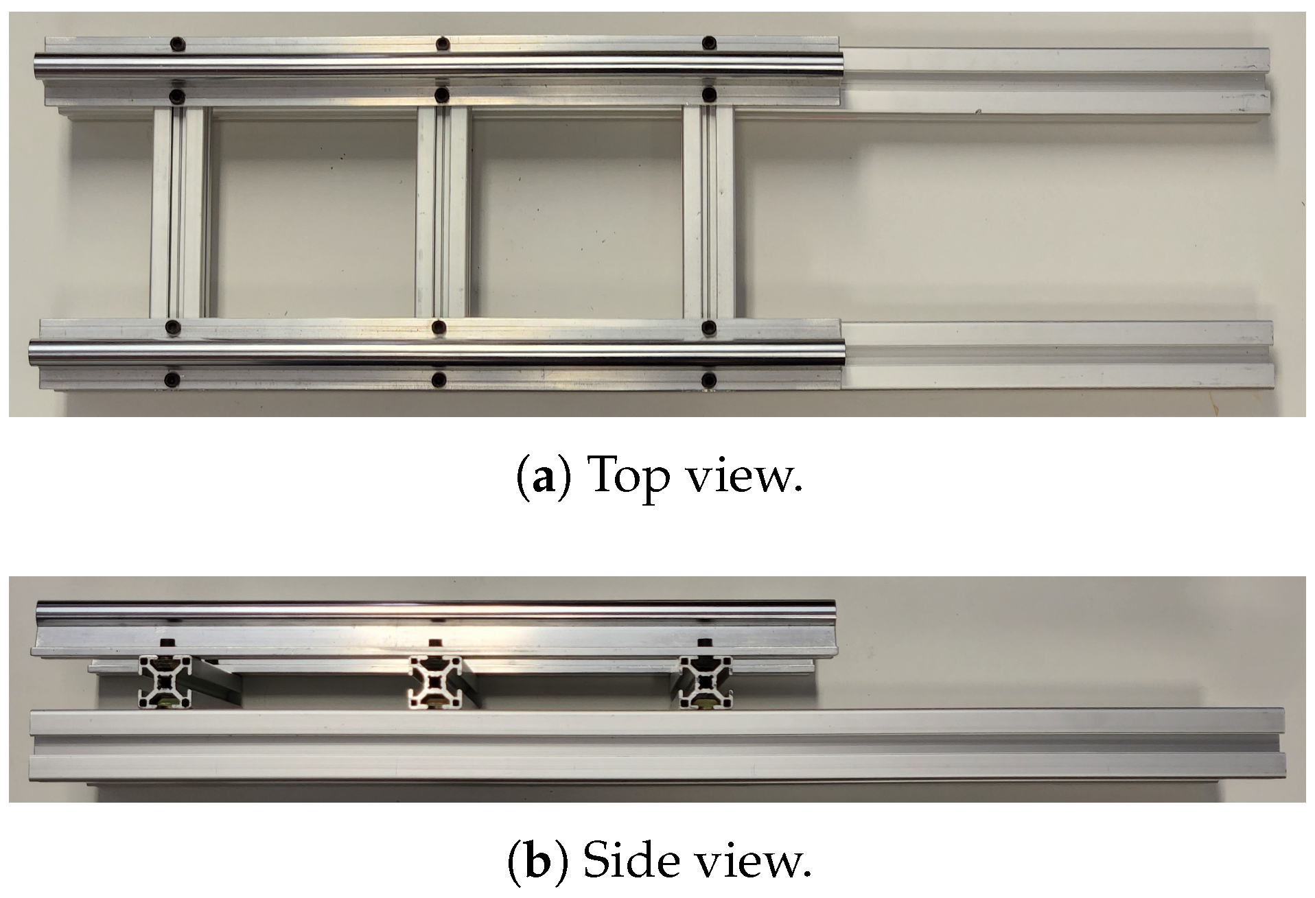
<p>Assembled base of test stand.</p> "> Figure 7
<p>Base with sliding platform mounted on test stand.</p> "> Figure 8
<p>Visualisation of steps for assembling the sample mount on the test stand. (<b>a</b>) Base mounted. (<b>b</b>) Lower plate added. (<b>c</b>) Threaded rods added. (<b>d</b>) Upper plate added.</p> "> Figure 9
<p>(<b>a</b>) Pulley block assembly. (<b>b</b>) Block mounted on test stand.</p> "> Figure 10
<p>Steps for assembling counterweight wire. (<b>a</b>) Wire tied around nut to secure in siding platform wire holder. (<b>b</b>) Wire threaded through hole drilled in bolt. (<b>c</b>) Threaded nut screwed into counterweight.</p> "> Figure 11
<p>Steps for fitting draw-wire holding block. (<b>a</b>) Assembled draw-wire holding block. (<b>b</b>) Holding block mounted to test stand.</p> "> Figure 12
<p>Front and back cut-outs in controller box. Indicated hole is not part of final design.</p> "> Figure 13
<p>Front panel connectors/wires. Indicated connectors are not part of the final design. (<b>a</b>) Connectors fitted to front panel with wires soldered. (<b>b</b>) Front view of front panel connectors. (<b>c</b>) Motor connection cables fitted through cable grommets.</p> "> Figure 14
<p>Power supply connections assembly. (<b>a</b>) Wires attached to plug. (<b>b</b>) Plug attached to rear panel and PSU terminals.</p> "> Figure 15
<p>Power supply and motor driver mounting. (<b>a</b>) Attached case sides and base to power supply. (<b>b</b>) Mounted motor driver onto side of power supply.</p> "> Figure 16
<p>Wire connections for the motor driver. The Tiva ground for power is connected via the PUL- port to minimise loop size for this rapidly switching signal.</p> "> Figure 17
<p>Tiva mounting. (<b>a</b>) Back-stop added. (<b>b</b>) Back-stop secured with screws and Tiva inserted. (<b>c</b>) First clip fitted and second half-on to demonstrate process. (<b>d</b>) Tiva fully secured.</p> "> Figure 18
<p>Pin connection positions on the Tiva board. Note, power source selection switch position.</p> "> Figure 19
<p>Pin numbering used on 8-pin circular connectors.</p> "> Figure 20
<p>Inline voltage divider for Torque sensor output to Tiva input. Shaded areas show where to cover connections with electrical tape. Silver ovals show soldering locations.</p> "> Figure 21
<p>Fully wired controller box.</p> "> Figure 22
<p>Interactions with main window to add, and connect to, the test rig.</p> "> Figure 23
<p>Diagnostics window with normal display.</p> "> Figure 24
<p>Bone screw test rig settings/control window.</p> "> Figure 25
<p>Experimental setup with off-the-shelf torque sensor connected to test rig shaft.</p> "> Figure 26
<p>Visual clarification of how changing the spacing in the coupler changes the amount of magnetic field coupling into the torque sensor shaft. The magnetic permeability of the air and aluminium is very low and similar in comparison to that of the steel screw-bit holder and torque sensor shaft.</p> "> Figure 27
<p>Error in torque measurement over tested range with different magnetic coupling.</p> "> Figure 28
<p>Error from perfect profile under different loading conditions.</p> "> Figure A1
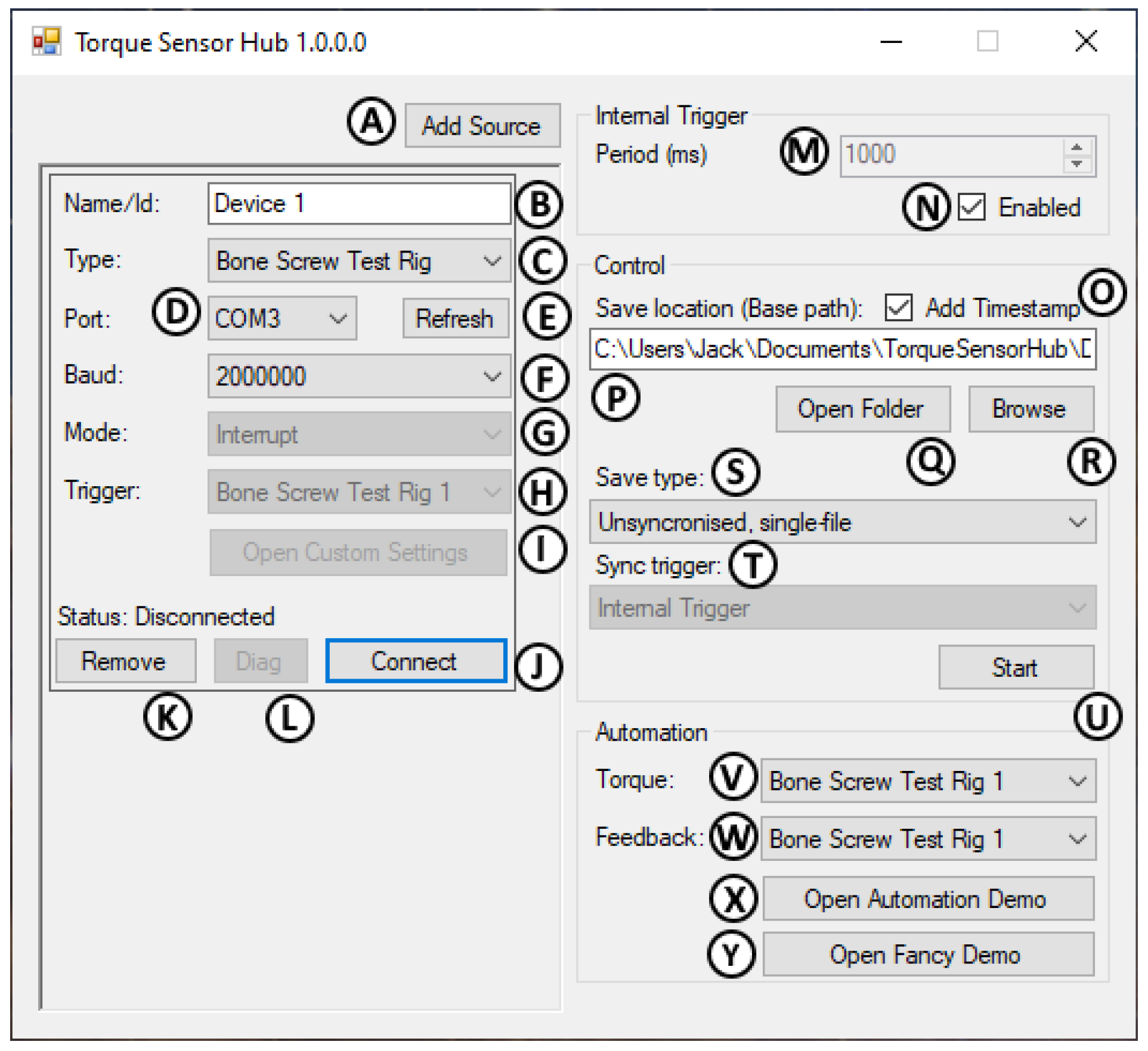
<p>Main window with labeled controls.</p> "> Figure A2
<p>Settings window with labeled controls.</p> "> Figure A3
<p>Diagnostics window with labeled controls.</p> "> Figure A4
<p>Basic demo window with labeled controls.</p> "> Figure A5
<p>Fancy demo window with labeled controls.</p> ">
Abstract
:1. Introduction
2. Design
2.1. Concept
2.2. Test Stand
2.3. Controller Hardware
2.4. Controller Firmware
2.5. Software
2.6. Modification
3. Build Instructions
3.1. Bill of Materials/Tools
3.2. Test Stand
3.3. Controller
3.4. Connection
4. Operating Instructions
4.1. Note on Power Sequencing
4.2. Initial Setup/Testing
Setup Summary
- Power and connect the test rig.
- Open the software and add a new device.
- Set the “Bone Screw Test Rig” device type and check the port; Connect to the device.
- Open the custom settings window and verify measurements are working.
- Carefully test the motor with small jog commands. If the direction is incorrect or the motor spins violently, check the wiring of the motor and the configuration of the motor driver.
4.3. General Use
General Use Summary
- Power test rig, add the device in software and connect.
- Open custom settings and configure experimental parameters as necessary. A test run is advised before using a specimen. See above or Appendix B for descriptions of settings.
- Set data saving settings (notable folder/filename) in the main window.
- For each experiment:
- (a)
- Set up the sample in the clamp, and place the screw in position.
- (b)
- Zero positions as desired.
- (c)
- Click “Start” in the main window to begin recording.
- (d)
- Click “Start Insertion” in test rig settings to begin insertion.
- (e)
- Wait for the experiment to finish.
- (f)
- Click “Stop” in the main window to finish recording.
4.4. Software Use Reference
4.5. New Device Classes
5. Validation
5.1. Torque Comparison
5.2. Positional Repeatability
5.3. Velocity Profile Accuracy
6. Conclusions
Supplementary Materials
| Name | Type | Description |
| S1 | ZIP Archive (.zip) | .stl files for 3D printing. |
| S2 | ZIP Archive (.zip) | .step files for machinable parts. |
| S3 | ZIP Archive (.zip) | .pdf drawings for machinable parts. |
| S4 | ZIP Archive (.zip) | CCS Project for Controller Firmware. |
| S5 | Binary File (.bin) | Compiled Controller Firmware. |
| S6 | ZIP Archive (.zip) | Visual Studio Project for Controller Interface Software. |
| S7 | ZIP Archive (.zip) | Compiled Controller Interface Software. |
| S8 | MATLAB Script (.m) | MATLAB Script used to generate FIR filter coefficients. |
Author Contributions
Funding
Institutional Review Board Statement
Informed Consent Statement
Data Availability Statement
Acknowledgments
Conflicts of Interest
Abbreviations
| (G)UI | (Graphical) User Interface |
| PC | Personal Computer |
| CPR | Counts per Revolution |
| PPR | Pulses per Revolution |
| BOM | Bill of Materials |
| USB | Universal Serial Bus |
| PSU | Power Supply Unit |
| (V)DC | (Volts) Direct Current |
| DMA | Direct Memory Access |
| DIN | Deutsches Institut für Normung |
| ADC | Analog-to-Digital Converter |
| CPU | Central Processing Unit |
| EEPROM | Electronically-Erasable and Programmable Read-Only-Memory |
| GPIO | General Purpose Input/Output |
| PWM | Pulse-Width Modulation |
| API | Application Programming Interface |
| FIR | Finite Impulse Response |
| HTTP | Hypertext Transfer Protocol |
| IP | Internet Protocol |
| URL | Uniform Resource Locator |
| FDM | Fused Deposition Molding |
| DIP | Dual Inline Package |
| MAC | Medium Access Control |
| CAD | Computer-Aided Design |
| STL | STereoLithography |
Appendix A. Hardware Modification
Appendix B. Software UI Reference

| Code | Name | Default Value | Remarks |
|---|---|---|---|
| ena | Motor Enabled. | 0 | 0 = Motor shut down, 1 = Motor powered. Not saved/loaded in EEPROM. |
| ind | Insert Distance. | 12 × 4000 | How many pulses in insertion (4000 per revolution). |
| rvd | Reverse Distance. | 14 × 4000 | How many pulses to reverse insertion (4000 per revolution). |
| jgd | Jog Distance. | 1 | How many pulses per jog action (4000 per revolution). |
| pau | Full Insertion Pause. | 1000 | Wait time between insertion and reversal in ms. |
| trp | Trapezoidal Enabled. | 0 | 0 = constant profile, 1 = trapezoidal profile. |
| ins | Insert Speed. | 2000 | How fast to insert screw (4000 = 60 RPM). |
| rmp | Trapezoid Ramp Time. | 150 | Time in trapezoidal ramp segments in ms. |
| hdt | Trapezoid High Dwell Time. | 200 | Time in trapezoidal full-speed segments in ms. |
| ldt | Trapezoid Low Dwell Time. | 250 | Time in trapezoidal stopped segments in ms. |
| dpt | Distance Per Trapezoid. | 200 | Total pulses to travel per trapezoidal cycle (4000 per revolution). |
| tlm | Torque Limit. | 1000 | Unimplemented. |
| rvs | Reverse Speed. | −1 | −1 = Same as insert speed, otherwise sets reverse speed (4000 = 60 RPM). |
| inv | Invert Rotation. | 0 | 0 = normal, 1 = invert all motion and rotational sensors (e.g., left-handed screw thread). |
| ID | Name | Description |
|---|---|---|
| A | Add source button | Adds a device to the device list below. |
| B | Device name | Used to identify device in output file. |
| C | Device type | Used to select what class this device is. |
| D | Port/Address | Used to specify which port/address the device can be accessed at. |
| E | Refresh ports | Refresh the port list after plugging/unplugging a device. |
| F | Baud rate | Select baud rate to use for serial devices. |
| G | Device mode | (If multiple) select whether device sends data on its own(Interrupt), or when requested(Poll). |
| H | Device trigger | (When polling device) Select what triggers a polled data-point. |
| I | Custom settings | (If supported) Open custom device-specific settings window. This is used extensively for controlling the test rig. |
| J | Remove device | Delete entry from devices list. |
| K | Diagnostics | Open diagnostics window for device (Described below). |
| L | Connect/Disconnect | Start/stop link between software and device. |
| M | Internal trigger period | Selects how often polling devices with the “Internal” trigger will send data. |
| N | Internal trigger enable | Selects whether internal trigger is currently triggering devices. If not needed it is best to leave this off for performance reasons. |
| O | Add timestamp | Adds current time between filename and extension so every output file is uniquely named and traceable. |
| P | Filename | Filename to save output files. If multiple files are generated a folder with the name will be created instead with files named after device Ids. If timestamp is enabled this will be appended to the file/folder name. |
| Q | Open folder | Opens system file explorer in the output files’ directory/folder. |
| R | Browse | Opens dialog to select file location/name. |
| S | Save type | Select between: single/multifile, with single file using column name prefixes for multiple devices, and multi-file using no prefix but saving different devices outputs in different files; and synchronised/unsynchronised, with synchronised buffering the most recent point and writing to files once on each specified sync trigger, and unsynchronised writing points from each device as they are received. |
| T | Sync trigger | Used for synchronised file recording settings. |
| U | Start/Stop recording | Starts or stops recording device data to file(s). Files are created with the timestamp when start is clicked. |
| V | Demo data source | Device to use for torque/position data in smart-screwdriver demo. |
| W | Demo feedback target | Device to control from smart-screwdriver demo. |
| X | Open basic demo | Opens simple smart-screwdriver demo with graphed data for debugging. |
| Y | Open fancy demo | Opens smart-screwdriver demo with “fancy” graphics for presentations, trade shows, etc. |

| ID | Name | Description |
|---|---|---|
| A | Command input | Enter customs commands to send over serial link. |
| B | Send button | Sends command that was typed (also by pressing enter/return). |
| C | Command feedback | Status sent from test-rig after running command also shows any status from commands run by all other buttons. |
| D | Setting selection | Select setting to change (automatically retrieves current value when selected). |
| E | Setting value | Value retrieved from test rig or value to send to test rig. |
| F | Get setting button | Retrieve selected setting. |
| G | Set setting button | Update test rig setting with given value. |
| H | Save EEPROM | Save current settings to test rig EEPROM, so they will be loaded on startup, otherwise, they will be restored to the previously saved values when power-cycling (which can also be desirable). |
| I | Load EEPROM | Restore saved settings from EEPROM. |
| J | Reset to defaults | Restore saved EEPROM setting to hard-coded default settings, however, currently active settings will not be reset until EEPROM load or power cycle. |
| K | Start insertion | Turns on motor and starts controlled motion with motor according to currently active settings. |
| L | Stop insertion | Stops current controlled motion and turns off motor. |
| M | Pause insertion | Suspends current insertion, but keeps current state. There may be a few seconds delay as the motor completes the current motion segments first. Clicking start again will resume from the current position and complete the programmed insertion. Up to 2 motion segments are queued in the firmware, with each phase of a trapezoidal profile being one segment, and constant-velocity profiles are split into segments as per the “distance per trapezoid” setting (default 2000 or 0.5 revolutions). |
| N | Lock UI | Prevents accidentally clicking buttons (e.g., stop). Useful for long-running tests. Click and drag to lock or unlock. |
| O | Motor on | Enable motor power. Will prevent hand-turning of the motor up to its holding torque. |
| P | Motor off | Disable motor power, e.g., to allow hand-turning. |
| Q | Restart | Reboot micro-controller. Similar to a power cycle but notably may not clear motor driver faults. |
| R | Jog multiplier | Repeats the “jog distance” this many times when jogged clockwise or counter clockwise. |
| S | Clockwise Jog | Rotates the motor clockwise based on jog distance setting and jog multiplier. Will be reversed by “invert motion” setting. |
| T | Counterclockwise jog | As above but opposite direction. |
| U | Torque value | Current value of measured torque. Should fluctuate slightly due to noise; no fluctuation may indicate the firmware has crashed. |
| V | Rotation value | Current incremental rotation in degrees. |
| W | Linear position value | Current incremental position in mm. |
| X | Run self-calibration | Runs the firmware torque self-calibration routine. This corrects for zero-point and rotational modulation of the torque signal by rotating the shaft and sampling the offsets from zero. Once complete an internal lookup-table provides correction in the firmware. Run this with screwdriver bits fitted, but otherwise no load. |
| Y | Zero encoders | Resets zero point of position and rotation to current position. |
| Z | Rotation zero offset | Instead of resetting encoder value to zero, it is reset to this value. |
| AA | Linear zero offset | Instead of resetting encoder value to zero, it is reset to this value. |

| ID | Name | Description |
|---|---|---|
| A | Device name | Which device the diagnostics are being shown for. |
| B | Port | Which port/address the device is using. |
| C | Data rate | How many data points received in 1 s. |
| D | Average period | Average time between point in ms. |
| E | Period standard deviation | Standard deviation in period times in ms. |
| F | Max period | Longest period in the last second. |
| G | Min period | Shortest period int he last second. |
| H | Period distribution | Graph of periods between data points in last 1 s. Scaled for 1 ms expected average. |

| ID | Name | Description |
|---|---|---|
| A | Start insertion | Send command to controlled device to start insertion (for test rig this is the same as the button in the customs settings). Will also start plotting data and estimating stripping torque. |
| B | Stop insertion | Send command to controlled device to stop insertion. Also, stops plotting data. |
| C | Auto stop | Stops insertion automatically when estimated limit is exceeded. This condition is suppressed for the first 10 revolutions to allow the estimate to stabilize. |
| D | Screw type selection | Reference screw for “Known Value” plot, used as a-priori geometry information for the torque limit algorithm. |
| E | Material selection | Reference material for “Known Value” plot. |
| F | Torque plot | Shows measured torque values and progressively updated estimated limit. |
| G | Strength plot | Shows estimated strength from torque-rotation values and screw geometry compared to an estimate of the known value based on material datasheet properties. |

| ID | Name | Description |
|---|---|---|
| A | Start insertion | Send command to controlled device to start insertion (for test rig this is the same as the button in the customs settings). Will also start plotting data and estimating stripping torque. |
| B | Stop insertion | Send command to controlled device to stop insertion. Also, stops plotting data. |
| C | Auto stop | Stops insertion automatically when 80% of estimated limit is exceeded. This condition is suppressed for the first 10 revolutions to allow the estimate to stabilize. |
| D | Screw type selection | Reference screw for gauge visual scaling, used as a-priori geometry information for the torque limit algorithm. |
| E | Material selection | Reference material for gauge visual scaling. |
| F | Fullscreen | Show gauge in fullscreen, e.g., for demos/trade shows. |
| G | Torque indicator | Indicates currently measured torque value. |
| H | Torque target | Indicates 80% of torque limit. |
| I | Under-torque range | Yellow area indicates less than 70% of estimated limit. |
| J | Ideal torque range | Green area indicates 70–100% of estimated limit. |
| K | Over-torque range | Red area indicates exceeding 100% of the estimated torque limit. |
| L | Torque value | Numeric value for current torque. |
| M | Target value | Numeric value for 80% of estimated torque limit. |
| N | Target range | Numeric values for 70% to 100% of estimated torque limit. |

Appendix C. Troubleshooting
| Problem | Possible Cause | Remedy |
|---|---|---|
| Controller | ||
| Data from test rig not updating/empty output file. | Test rig firmware crashed. | Power cycle test rig and re-connect. |
| USB connection failed. | Disconnect USB, power cycle test rig, then re-connect cable and re-connect in software. | |
| Specific sensor data stuck at zero. | Sensor cable disconnected. | Check cable correctly plugged in. |
| Wiring error. | Check internal connections in controller against reference (unplug power cable first!). | |
| Motor not turning. | Motor driver power fault. | Power-cycle and reconnect test-rig in software, making sure to remove USB cable during power-cycle. |
| Other transient motor fault. | ||
| Incorrect power sequencing. | Ensure controller box is turned on and wait a few seconds before connecting USB cable. | |
| Motor or feedback cable disconnected. | Ensure cables are securely connected and screwed together. Check that cable connections have not been pulled out of motor driver inside the controller. | |
| Data from interrupt-based source not updating/empty output file. | No interrupt set/enabled. | Check interrupt settings and if using internal trigger check that it is turned on. |
Appendix D. New Device Guide
Appendix D.1. General
- report its data format by implementing the GetFormat() method;
- report “Interrupt” or “Poll” mode by implementing the GetModes() method, or overriding the “PollSupported” or “InterruptSupported” properties from BaseSerialDevice;
- if “Polling”, implement the SetTrigger() method (IDevice) to listen for triggers from the passed object, or use the Triggered() method (BaseSerialDevce), and send data points in response (or trigger the reading if necessary and send as soon as possible);
- if “Interrupt”, send data points whenever ready;
- if IDevice, report custom settings support by implementing the the SupportCustomDialog() method, and if true must implement the OpenCustomDialog() method;
- implement all methods in the IDevice or all abstract methods in BaseSerialDevice (depending on inheritance);
- if IDevice, assign all EventHandlers to “delegate { }”;
- use the LoggingDevice attribute to give the device a user-friendly name and make it appear in the device list.
Appendix D.2. Serial Interface
- implement the SetupDevice()/StopDevice() methods to perform any required connection/disconnection commands;
- implement the ProcessLine() method to parse data from the device and send data points;
- implement the DefaultBaud() method to configure the device’s normal baud rate.
Appendix D.3. Other Interfaces
- implement SelectedType() / DeselectedType() to enable or disable the relevant configuration options by invoking the “Enable[…]Select”, “Disable[…]Select”, and enable/disable button events; make sure to disable anything that was enabled when the type is deselected;
- when configured as polling/interrupt by default or through a setting, enable either trigger selection(polling) or trigger use(interrupt);
- when sending a data point as an interrupt, also invoke the trigger event to synchronously trigger other connected devices;
- implement Connect() /Disconnect() to connect or disconnect the device; also locking/disabling settings as necessary and using the Connected/Disconnected events to report the success of this;
- if needing a non-serializable port/address, implement the IIPDevice interface to allow free text entry in the port field (useful for IP, URL, MAC); then GetPort() / SetPort() semantically refer to this address;
- implement GetBauds() / GetModes() / GetPorts() / SetBaud() / SetMode() / SetPort() / GetPort() / DefaultBaud() as relevant to the required settings; GetPorts() may list serial ports, or can foreseeably list some other serialised device list (e.g., discovered Bluetooth devices, although completely unimplemented currently);
References
- Rybczynski, W. One Good Turn: A Natural History of the Screwdriver and the Screw; Simon & Schuster: New York, NY, USA, 2000. [Google Scholar]
- Fernandez, D.L. Anterior Bone Grafting and Conventional Lag Screw Fixation to Treat Scaphoid Nonunions. J. Hand Surg. 1990, 15, 140–147. [Google Scholar] [CrossRef] [PubMed]
- Cuny, C.; Scarlat, M.M.; Irrazi, M.; Beau, P.; Wenger, V.; Ionescu, N.; Berrichi, A. The Telegraph Nail for Proximal Humeral Fractures: A Prospective Four-Year Study. J. Shoulder Elb. Surg. 2008, 17, 539–545. [Google Scholar] [CrossRef] [PubMed]
- Barber, F.A.; Herbert, M.A.; Beavis, R.C.; Barrera Oro, F. Suture Anchor Materials, Eyelets, and Designs: Update 2008. Arthrosc. J. Arthrosc. Relat. Surg. 2008, 24, 859–867. [Google Scholar] [CrossRef] [PubMed]
- Kieser, D.C.; Ailabouni, R.; Kieser, S.C.; Wyatt, M.C.; Armour, P.C.; Coates, M.H.; Hooper, G.J. The Use of an Ossis Custom 3D-printed Tri-Flanged Acetabular Implant for Major Bone Loss: Minimum 2-Year Follow-Up. Hip Int. 2018, 28, 668–674. [Google Scholar] [CrossRef] [PubMed]
- Yang, C.; Han, X.; Wang, J.; Yuan, Z.; Wang, T.; Zhao, M.; Han, G. Cemented versus Uncemented Femoral Component Total Hip Arthroplasty in Elderly Patients with Primary Osteoporosis: Retrospective Analysis with 5-Year Follow-Up. J. Int. Med. Res. 2019, 47, 1610–1619. [Google Scholar] [CrossRef] [PubMed]
- Evans, M.; Spencer, M.; Wang, Q.; White, S.H.; Cunningham, J.L. Design and Testing of External Fixator Bone Screws. J. Biomed. Eng. 1990, 12, 457–462. [Google Scholar] [CrossRef] [PubMed]
- Feroz Dinah, A.; Mears, S.C.; Knight, T.A.; Soin, S.P.; Campbell, J.T.; Belkoff, S.M. Inadvertent Screw Stripping During Ankle Fracture Fixation in Elderly Bone. Geriatr. Orthop. Surg. Rehabil. 2011, 2, 86–89. [Google Scholar] [CrossRef] [PubMed]
- Li, B.; Aspden, R.M. Composition and Mechanical Properties of Cancellous Bone from the Femoral Head of Patients with Osteoporosis or Osteoarthritis. J. Bone Miner. Res. 1997, 12, 641–651. [Google Scholar] [CrossRef] [PubMed]
- Stoesz, M.J.; Gustafson, P.A.; Patel, B.V.; Jastifer, J.R.; Chess, J.L. Surgeon Perception of Cancellous Screw Fixation. J. Orthop. Trauma 2014, 28, e1. [Google Scholar] [CrossRef] [PubMed]
- Thomas, R.L.; Bouazza-Marouf, K.; Taylor, G.J.S. Automated Surgical Screwdriver: Automated Screw Placement. Proc. Inst. Mech. Eng. Part H J. Eng. Med. 2008, 222, 817–827. [Google Scholar] [CrossRef] [PubMed]
- Reynolds, K.J.; Mohtar, A.A.; Cleek, T.M.; Ryan, M.K.; Hearn, T.C. Automated Bone Screw Tightening to Adaptive Levels of Stripping Torque. J. Orthop. Trauma 2017, 31, 321–325. [Google Scholar] [CrossRef] [PubMed]
- Wright, B.J.; Grigg, S.; Bergsaker, A.S.; Brattgjerd, J.E.; Steen, H.; Pullin, R. Real Time Monitoring of Screw Insertion Using Acoustic Emission Can Predict Screw Stripping in Human Cancellous Bone. Clin. Biomech. 2020, 76, 105026. [Google Scholar] [CrossRef] [PubMed]
- Wilkie, J.; Docherty, P.D.; Möller, K. A Simple Screwing Process Model for Bone Material Identification. In Proceedings of the 14th Symposium on Automation in Medical Engineering, AUTOMED, Lübeck, Germany, 2–3 March 2020; Volume 1, p. 038. [Google Scholar] [CrossRef]
- Wilkie, J.; Docherty, P.D.; Stieglitz, T.; Möller, K. Geometric Generalization of Self Tapping Screw Insertion Model. In Proceedings of the 2021 43rd Annual International Conference of the IEEE Engineering in Medicine Biology Society (EMBC), Virtual, 1–5 November 2021; pp. 4339–4387. [Google Scholar] [CrossRef]
- Wilkie, J.; Docherty, P.D.; Möller, K. Stripping Torque Model for Bone Screws. IFAC-PapersOnLine 2021, 54, 442–447. [Google Scholar] [CrossRef]
- Wilkie, J.A.; Rauter, G.; Möller, K. Determining Relationship between Bone Screw Insertion Torque and Insertion Speed: Bestimmung Des Zusammenhangs Zwischen Dem Drehmoment Beim Eindrehen von Knochenschrauben Und Der Eindrehgeschwindigkeit. at - Automatisierungstechnik 2022, 70, 976–991. [Google Scholar] [CrossRef]
- Betts, J.L.; Brinkley, F.M.; Priddy, L.B.; Priddy, M.W. Low-Speed Instrumented Drill Press for Bone Screw Insertion. HardwareX 2023, 16, e00474. [Google Scholar] [CrossRef] [PubMed]
- Calcagno, B.O. Acquisition of an Instron Electropuls E3000 Instrument for Mechanical Testing; University of Puerto Rico at Mayaguez Mayaguez: Mayagüez, Puerto Rico, 2015. [Google Scholar] [CrossRef]
- Wilkie, J.; Docherty, P.D.; Stieglitz, T.; Möller, K. Quantifying Accuracy of Self-Tapping Screw Models. In Proceedings of the 2021 43rd Annual International Conference of the IEEE Engineering in Medicine Biology Society (EMBC), Virtual, 1–5 November 2021; pp. 4391–4394. [Google Scholar] [CrossRef]


| Intended Tool | Alternative(s) | Remarks |
|---|---|---|
| Basic FDM 3D printer. | Order 3D printed parts online. | For 3D printed mounts. |
| Milling machine + Lathe. | Order machined parts online. | For machined parts. |
| Tap and die set. | For threaded holes. | |
| Screwdriver with bit set. | Allen key set. | Depending on the screw heads ordered. |
| Hand file. | ||
| Soldering station + solder. | Soldering iron + solder. | Leaded solder may be easier to work with, however, consider if you have any toxicity/RoHS requirements/regulations to follow. |
| Electrical tape. | Cellulose-tape. | Insulating solder joints and holding connections together. |
| Part | Unit (EUR) | Qty | Total (EUR) | Reference Supplier | Remarks/Specifics |
|---|---|---|---|---|---|
| Test Rig Sensors | 2543.66 | ||||
| Torque sensor | 2230.06 | 1 | 2230.06 | NCTE AG | NCTE 2300-5-1-AU-0-0 |
| Draw-wire encoder | 313.60 | 1 | 313.60 | Fritz Kübler GmbH | D5.2501.2421.1000 |
| Test Rig Motion | 276.65 | ||||
| Stepper motor | 64.84 | 1 | 64.84 | STEPPERONLINE | 34HS46-6004D-E1000 |
| Linear Bearings | 14.82 | 4 | 56.29 | Tuli d.o.o. | SME 16 UU |
| Linear Rails | 25.82 | 2 | 51.63 | Tuli d.o.o. | SA 16 (0.45 m) |
| Sensor-Bit Coupler | 53.00 | 1 | 53.00 | MISUMI Europa GmbH | SDWA-47C-9K3X10 |
| Motor-Sensor Coupler | 44.50 | 1 | 44.50 | MISUMI Europa GmbH | EK1/20/A/14/9 |
| Motor bracket | 6.39 | 1 | 6.39 | STEPPERONLINE | ST-M7 |
| Test Rig Structure + Fasteners | 163.91 | ||||
| Main Supports | 10.91 | 2 | 21.83 | myaluprofil.de | 40 × 40 × 700 groove 10 B-type |
| Clamp Base | 20.44 | 1 | 20.44 | myaluprofil.de | 100 × 100 × 200 groove 10 B-type |
| Main Cross-Supports | 2.24 | 3 | 6.71 | myaluprofil.de | 30 × 30 × 200 groove 8 B-type |
| 8 B-type M5 T-nuts | 0.20 | 12 | 2.40 | myaluprofil.de | H208HM5 |
| 8 B-type M6 T-nuts | 0.20 | 6 | 1.20 | myaluprofil.de | H208HM6 |
| 10 B-type M6 T-nuts | 0.27 | 8 | 2.16 | myaluprofil.de | H210HM6 |
| 10 B-type M8 T-nuts | 0.27 | 2 | 0.54 | myaluprofil.de | H210HM8 |
| Angle 30 × 30 8 B-type | 0.80 | 2 | 1.60 | myaluprofil.de | H208W30A |
| Aluminium Plate 5 mm | 24.70 | 1 | 24.70 | metallstore24.de | 240 × 240 × 5 mm |
| Aluminium Plate 20 mm | 13.87 | 1 | 13.87 | metallstore24.de | 100 × 100 × 20 mm |
| M3x10 Screw | 50(2) | 4.09 | screwsandmore.de | DIN 912 A2 M3X10 | |
| M3.5x16 Screw | 25(2) | 12.49 | screwsandmore.de | DIN 912 A2 M3.5X10 | |
| M4x12 Socket Screw | 50(4) | 3.19 | screwsandmore.de | DIN 912 A2 M4X12 | |
| M5x10 Socket Screw | 50(29) | 6.99 | screwsandmore.de | DIN 912 A2 M5X10 | |
| M5x40 Socket Screw | 10(1) | 3.49 | screwsandmore.de | DIN 912 A2 M5X40 | |
| M6x16 Socket Screw | 10(6) | 2.69 | screwsandmore.de | DIN 912 A2 M6X16 | |
| M6x30 Socket Screw | 10 | 4.09 | screwsandmore.de | DIN 912 A2 M6X30 | |
| M6x35 Socket Screw | 10 | 4.09 | screwsandmore.de | DIN 912 A2 M6X35 | |
| M8x16 Socket Screw | 10(2) | 3.49 | screwsandmore.de | DIN 912 A2 M8X16 | |
| M6 Nut | 50(14) | 3.59 | screwsandmore.de | DIN 934 A2 M6 | |
| M6 Threaded Rod | 5.59 | 1 | 5.59 | screwsandmore.de | DIN 976 A2 M6X250 |
| M6 Washer | 50(4) | 4.99 | screwsandmore.de | DIN 9021 A2 6.4 | |
| M8 Washer | 50(32) | 6.99 | screwsandmore.de | DIN 9021 A2 8.4 | |
| M6x16 Hex Bolt | 10(1) | 2.69 | screwsandmore.de | DIN 933 A2 M6X16 | |
| Total | 2984.22 | ||||
| Part | Unit (EUR) | Qty | Total (EUR) | Reference Supplier | Remarks/Specifics |
|---|---|---|---|---|---|
| Controller | 347.61 | ||||
| Chassis | 131.96 | 1 | 131.96 | RS Online | 1.5Ux279Dx305W |
| Motor Driver | 51.79 | 1 | 51.79 | STEPPERONLINE | CL86T V4.1 (Authors have V3.0) |
| Microcontroller | 31.86 | 1 | 31.86 | RS Online | EK-TM4C123GXL |
| PSU | 30.04 | 1 | 30.04 | STEPPERONLINE | S-350-48 |
| Plug Module | 10.47 | 1 | 10.57 | RS Online | RS Part 870-3271 |
| 10 A Fuse | 0.48 | 10 | 4.82 | RS Online | RS Part 563-592 |
| Fuse Holder | 3.88 | 1 | 3.88 | RS Online | RS Part 498-2653 |
| 0.254″ Header Cables | 20 | 2.31 | Digikey | Digikey Part 1568-1513-ND | |
| Jumper Wires | 140 | 7.07 | Digikey | Digikey Part 438-1049-ND | |
| M2.5 Nut | 100(16) | 4.19 | screwsandmore.de | DIN 934 A2 M2.5 | |
| M2.5x10 Slot Screw | 50(16) | 4.09 | screwsandmore.de | DIN 85 A2 M2.5X10 | |
| M4x6 Slot Screw | 25(4) | 2.69 | screwsandmore.de | DIN 85 A2 M4X6 | |
| M4x10 Slot Screw | 25(1) | 2.69 | screwsandmore.de | DIN 85 A2 M4X10 | |
| THT Resistors | Negligible | Generic | For voltage divider (56k + 27k) | ||
| 3D Printed Mounts | Variable | Self-made | |||
| Case Cable Grommets | 5.43 | 25(2) | 5.43 | RS Online | RS Part 817-8877 |
| Torque cable plug | 20.71 | 1 | 20.71 | RS Online | RS Part 734-5555 |
| Torque panel receptacle | 22.21 | 1 | 22.21 | RS Online | RS Part 734-5785 |
| Draw-wire cable plug | 5.84 | 1 | 5.84 | RS Online | RS Part 786-3454 |
| Draw-wire receptacle | 5.46 | 1 | 5.46 | RS Online | RS Part 786-3435 |
| Test Stand Total | 2984.22 | ||||
| Grand Total | 3331.83 | ||||
| Pin | Wire Colour | Name | Connected to |
|---|---|---|---|
| 1 | White | USB D− | N.C. |
| 2 | Brown | USB D+ | N.C. |
| 3 | Green | Encoder A | Tiva PD6 |
| 4 | Yellow | Encoder B | Tiva PD7 |
| 5 | Grey | Analogue GND | Tiva GND |
| 6 | Pink | Torque | Tiva PD0 (Through voltage divider) |
| 7 | Blue | Power Ground | Stepper Driver EGND |
| 8 | Red | VCC In | Stepper Driver VCC |
| Pin | Wire Colour | Name | Connected to |
|---|---|---|---|
| 1 | White | 0V | Tiva GND |
| 2 | Blue | Channel O | N.C. |
| 3 | Pink | Channel | N.C. |
| 4 | Gray | Channel B | Tiva PC6 |
| 5 | Yellow | Channel | N.C. |
| 6 | Green | Channel A | Tiva PC5 |
| 7 | Brown | +V | Tiva VBUS |
| 8 | Red | Channel | N.C. |
Disclaimer/Publisher’s Note: The statements, opinions and data contained in all publications are solely those of the individual author(s) and contributor(s) and not of MDPI and/or the editor(s). MDPI and/or the editor(s) disclaim responsibility for any injury to people or property resulting from any ideas, methods, instructions or products referred to in the content. |
© 2024 by the authors. Licensee MDPI, Basel, Switzerland. This article is an open access article distributed under the terms and conditions of the Creative Commons Attribution (CC BY) license (https://creativecommons.org/licenses/by/4.0/).
Share and Cite
Wilkie, J.; Rauter, G.; Möller, K. Horizontal Test Stand for Bone Screw Insertion. Hardware 2024, 2, 223-255. https://doi.org/10.3390/hardware2030011
Wilkie J, Rauter G, Möller K. Horizontal Test Stand for Bone Screw Insertion. Hardware. 2024; 2(3):223-255. https://doi.org/10.3390/hardware2030011
Chicago/Turabian StyleWilkie, Jack, Georg Rauter, and Knut Möller. 2024. "Horizontal Test Stand for Bone Screw Insertion" Hardware 2, no. 3: 223-255. https://doi.org/10.3390/hardware2030011