
Analysis of Longitudinal Cracking and Mold Flux Optimization in High-Speed Continuous Casting of Hyper-Peritectic Steel Thin Slabs

<p>(<b>a</b>) Phase diagram of solidification; (<b>b</b>) solidification two-phase zone transition diagram.</p> "> Figure 2
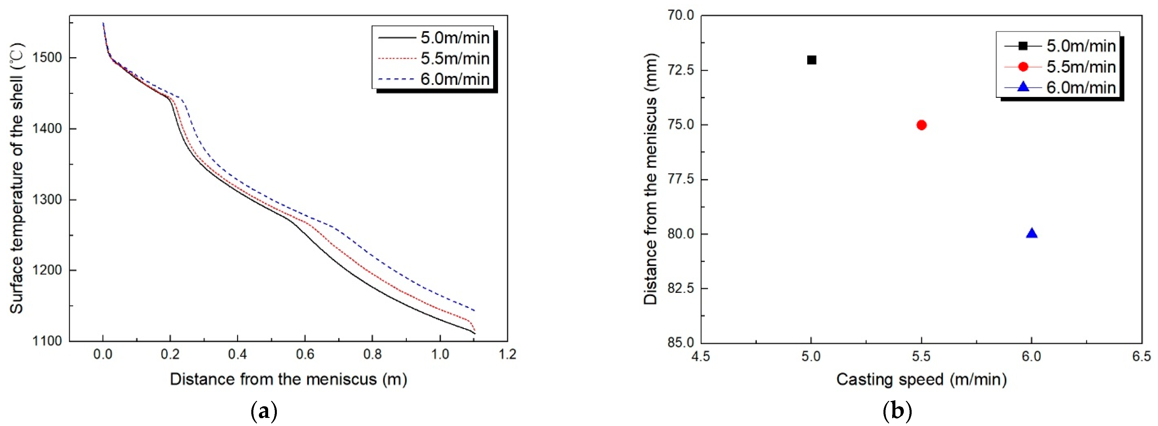
<p>(<b>a</b>) The surface temperatures of blank shells at different casting speeds; (<b>b</b>) the location of solid phase transformation on the surface of thin slab shells at different casting speeds.</p> "> Figure 3
<p>Thickness of thin slab shell at different casting speeds.</p> "> Figure 4
<p>Longitudinal crack morphology of hyper-peritectic steel continuous casting thin slab.</p> "> Figure 5
<p>Schematic diagram of SHTT-II crystallization temperature tester.</p> "> Figure 6
<p>Schematic diagram of viscosity experimental setup.</p> "> Figure 7
<p>Temperature control curve of melting point and melting rate tester.</p> "> Figure 8
<p>(<b>a</b>) Mold heat flow density; (<b>b</b>) liquid slag layer thickness and mold flux consumption statistics.</p> "> Figure 9
<p>(<b>a</b>) The overall surface condition of the casting thin slab after using the B-type mold flux; (<b>b</b>) local conditions of the surface of the casting thin slab after acid washing treatment.</p> ">
Abstract
:1. Introduction
2. Analysis of Longitudinal Cracking in Thin Slabs of Hyper-Peritectic Steel
2.1. Solidification Characteristics of Hyper-Peritectic Steel
2.2. Influence of the High-Speed Continuous Casting Process on Longitudinal Cracking on the Surface of Thin Slabs
- (1)
- The top of the model, which was the liquid level of the mold, adopted the first boundary condition, where the node temperature was equal to the pouring temperature of the steel liquid.
- (2)
- The thin slab model had a symmetrical structure with wide and narrow center planes and adopted adiabatic boundary conditions.
- (3)
- When the continuous casting thin slab in the mold cooled and solidified, a conduction heat transfer boundary condition was applied to its surface to transform the heat transfer resistance into an equivalent thermal resistance. The equivalent thermal resistance was then transformed into thermal conductivity.
3. Mold Flux Improvement Measures and Inspection Methods
3.1. Production Situation before Optimization
3.2. Mold Flux-Specific Improvement Measures
- (1)
- (2)
- Moderately reduce the viscosity of the mold flux to ensure a reasonable consumption and reduce the friction between the thin slab shell and the mold.
- (3)
- Increase the thickness of the liquid slag layer and reduce the slag circle, to offset the fluctuations in the liquid level and ensure the presence of liquid slag at the rising edge of the mold [22].
- (4)
- To avoid decline in the lubrication ability due to the enhanced mold flux crystallization ability, the melting and breaking temperatures of the mold flux should be moderately reduced to ensure that the lower part of the liquid slag film exists in the lower part of the mold, reducing friction of the thin slab cast inside the mold [23]. This ensures the quality of the surface avoids adhesion or an accidental breakout of the steel.
- (5)
- Maintain the stability of the mold flux liquid slag performance.
3.3. Testing Method for Physical and Chemical Properties of the Mold Flux
- (1)
- The crystallization temperature, incubation time, and critical cooling rate of the mold flux were determined using the SHTT-II melting crystallization temperature tester. The schematic diagram of the device is shown in Figure 5.
- (2)
- The viscosity of the mold flux was determined using a Brookfield rotating viscometer, heated to 1300 °C in a MoSi2 high-temperature furnace. The schematic diagram of the device is shown in Figure 6.
- (3)
- The melting temperature and speed of the mold flux were determined using an automatic slag melting point and melting speed tester. The melting speed was the time required for the slag samples to be completely melted at a constant temperature of 1350 °C. The temperature control curve is shown in Figure 7.
- (4)
- The thickness of the liquid slag layer was measured by inserting a steel plate above the liquid surface of the mold. The measurement site was located at a distance of half the width of the thin slab from the narrow copper plate.
4. Comparison of Mold Flux Effects
4.1. Mold Flux before Optimization
4.2. Optimized Mold Flux
4.3. Actual Use Effect of Mold Flux before and after Optimization
5. Conclusions
- (1)
- Through numerical simulation calculations using FactSage thermodynamic software and ANSYS finite element software, it was found that at a casting speed of 5.0~6.0 m/min, the solidification mode of hyper-peritectic steel in the thin slab mold was determined by δ → γ. The volume shrinkage caused by phase transformation resulted in a solid phase rate of up to 0.80~0.95. Furthermore, for every increase in casting speed of 0.5 m/min, the solid phase transformation position on the surface of the thin slab extended downwards by 4 mm and the average thickness of the thin slab decreased by 0.5 mm. In addition, factors such as air gaps and poor heat transfer in the initial solidification area resulted in the uneven growth of the primary thin slab, ultimately leading to longitudinal cracks on the surface.
- (2)
- To solve this, it was necessary to reduce the mold flux heat transfer performance and to ensure the lubrication of the lower part of the mold. Therefore, the basicity was increased from 1.60 to 1.68, the F- mass fraction was increased from 10.67% to 11.22%, the Na2O mass fraction was increased from 4.35% to 5.28%, the Li2O mass fraction was increased from 0.68% to 0.75%, and the carbon mass fraction was reduced from 10.86% to 10.47%. The crystallization performance of the mold flux was significantly improved, and the rheological properties were optimized, so that the lubricating ability of the mold flux was ensured while controlling the heat transfer.
- (3)
- After optimization and adjustment, the use of a new mold flux reduced the mold heat flow density, improved the mold flux liquid slag layer thickness and slag consumption, reduced the proportion of longitudinal cracks on the surface of the thin slab from 0.056% to 0.031%, and also significantly reduced the depth and length of longitudinal cracks. No sticker alarm or steel breakout accident occurred during the production process, and the expected effect was achieved.
Author Contributions
Funding
Data Availability Statement
Acknowledgments
Conflicts of Interest
References
- Wang, S.Z.; Gao, Z.H.; Wu, G.L.; Mao, X.P. Development status and prospects of thin slab continuous casting and rolling technology. Chin. J. Mech. Eng. 2022, 44, 534–545. [Google Scholar]
- Jayakrishna, P.; Ananda, S.; Chakraborty, S.; Ganguly, S.; Talukdar, P. Interfacial heat flux estimation in a funnel-shaped mould and analysis of solidification characteristics in thin slab continuous casting. J. Heat Trans. 2021, 143, 122401–122412. [Google Scholar] [CrossRef]
- Jiao, D.G.; Feng, H.J.; Feng, Y.P.; Xie, J. Progress and development direction of thin plate continuous casting and rolling technology under new situation. Foundry Tech. 2019, 9, 9111–9914. [Google Scholar]
- Zhu, L.G.; Yuan, Z.P.; Xiao, P.C.; Wang, X.J.; Yin, K.; Zhang, J. Research and optimization of mold flux for high speed continuous casting of low carbon steel thin slab. Iron Steel 2020, 55, 65–73+102. [Google Scholar]
- Li, L.P.; Wang, X.H.; Deng, X.X.; Ji, C.X. Process and quality control during high speed casting of low carbon conventional slab. J. Iron Steel Res. 2015, 22, 1–9. [Google Scholar] [CrossRef]
- Gao, X.; Li, H.X.; Han, L.; Santillana, B.; Ruvalcaba, D.; Zhuang, L.Z. Constitutive modeling and activation energy maps for a continuously cast hyperperitectic steel. Metall. Mater. Trans. A 2018, 49, 4633–4648. [Google Scholar] [CrossRef]
- Li, S.S.; Zhang, L.F.; Yang, X.G.; Li, M. Research on control of transverse cracks at the corner of continuous casting billets of hypo-peritectic steel. Steelmak 2016, 32, 67–72. [Google Scholar]
- Yao, C.G.; Yuan, S.Q.; Chen, L.; Wang, Z.J. Research and process optimization of corner cracks in Q235D continuous casting blooms of peritectic steel. Hot Working Tech. 2011, 40, 53–56. [Google Scholar]
- Li, Q.H.; Lan, P.; Wang, H.J.; Ai, H.Z.; Chen, D.L.; Wang, H.D. Formation and control of the surface defect in hypo-peritectic steel during continuous casting: A review. Int. J. Min. Met. Mater. 2023, 30, 2281–2296. [Google Scholar] [CrossRef]
- Furumai, K.; Aramaki, N.; Oikawa, K. Influence of heat flux different between wide and narrow face in continuous casting mould on unevenness of hypo-peritectic steel solidification at off-corner. Ironmak. Steelmak. 2022, 49, 1–15. [Google Scholar] [CrossRef]
- Konishi, J.; Militzer, M.; Samarasekera, I.V.; Brimacombe, J.K. Modeling the formation of longitudinal facial cracks during continuous casting of hypoperitectic steel. Metall. Mater. Trans. B 2002, 33, 413–423. [Google Scholar] [CrossRef]
- Zhang, X.M.; Wang, H.F.; Cheng, N.L. Study on the peritectic reaction of steel and the sensitivity of casting billet cracks. Contin. Cast. 2018, 43, 47–50. [Google Scholar]
- Wang, J.H.; Pan, S.Y.; Li, Y.S.; Shen, X.P.; Zhang, Q.Y.; Jia, D. A phase-field study of the peritectic reaction mechanisms in Fe-Ni alloys. Comp. Mater. Sci. 2023, 230, 112491–112501. [Google Scholar] [CrossRef]
- Bai, L.; Wang, B.; Zhong, H.G.; Ni, J.; Zhai, Q.J.; Zhang, J.Y. Experimental and numerical simulations of the solidification process in continuous casting of slab. Metals 2016, 6, 53–64. [Google Scholar] [CrossRef]
- Paweł, K.; Paweł, S.; Grzegorz, K.; Szymon, K.; Krystian, F. External surface quality of the graphite crystallizer as a factor influencing the temperature of the continuous casting process of ETP grade copper. Materials 2021, 14, 6309–6321. [Google Scholar] [CrossRef] [PubMed]
- Wang, M. Simulation Research on Solidification Heat Transfer of Thin Slab Continuous Casting at High Casting Speed. Master’s Thesis, Shenyang University of Technology, Shenyang, China, 12 June 2021. [Google Scholar]
- Liu, Z.X.; Yang, Y.S.; Xiao, P.C.; Zhu, L.G.; Zhu, R. Deformation behavior of billet shell in ultra-high speed thin slab continuous casting mold. Steelmak 2023, 39, 58–65. [Google Scholar]
- Li, Q.P.; Wen, G.H.; Chen, F.H.; Tang, P.; Hou, Z.B.; Mo, X.Y. Irregular initial solidification by mold thermal monitoring in the continuous casting of steels: A review. Int. J. Min. Met. Mater. 2023, 31, 1–13. [Google Scholar] [CrossRef]
- Gu, S.T.; Sun, M.F.; Wang, B.; Zhang, J.Y. Simulation and experimental study of fluid flow and solidification behavior in thin slabs continuous casting process under secondary electromagnetic stirring. Steel Res. Int. 2023, 95, 2300398–2300413. [Google Scholar] [CrossRef]
- Wang, Z.; Tang, P.; Mi, X.X.; Hu, Q.; Lu, Y.F.; Wen, G.H. Effect of w(CaF2) on crystallization properties of CaO-SiO2-Al2O3 based mold fluxes. Iron Steel 2018, 53, 38–44. [Google Scholar]
- Anisimov, K.N.; Longinov, A.M.; Gusev, M.P. Influence of mold flux on the thermal processes in the mold. Steel Trans. 2016, 46, 589–594. [Google Scholar] [CrossRef]
- Wu, J. Research on Lubrication Characteristics of Mold Flux for Continuous Casting Mold. Master’s Thesis, Yanshan University, Qinhuangdao, China, 15 June 2022. [Google Scholar]
- Zhu, L.L.; He, S.P.; Mao, J.H. Series planning of special thick plate continuous casting mold flux. Iron Steel 2016, 51, 44–48. [Google Scholar]
- Weng, J.J. Research and application of high basicity and high lubricity continuous casting mold flux. Steelmak 2016, 32, 52–54. [Google Scholar]
- Yang, J. Lubrication Characteristics and Heat Transfer Behaviors in Continuous Casting Mold for High Mn High Al Steel. Ph.D. Thesis, Northeastern University, Shenyang, China, 14 June 2018. [Google Scholar]
- Yuan, Z.P.; Zhu, L.G. Effect of Li2O on rheological properties, structure, and crystallization of mould flux for high-speed thin-slab continuous casting. Ironmak. Steelmak. 2022, 49, 226–237. [Google Scholar] [CrossRef]
- Gao, J.X.; Wen, G.H.; Sun, Q.H.; Tang, P. The influence of Na2O on the solidification and crystallization behavior of CaO-SiO2-Al2O3-based mold flux. Metall. Mater. Trans. B 2015, 46, 1850–1859. [Google Scholar] [CrossRef]
- Zhang, J.H.; Qi, J.; Liu, C.J.; Jiang, M.F. Effect of Li2O on the crystallization properties of CaO-Al2O3 based mold flux. J. Iron Steel Res. 2022, 34, 1211–1218. [Google Scholar]
- Wang, X.J.; Fan, Y.P.; Zhu, L.G.; Wang, L.J.; Wu, B.B.; Tian, K. Influence of CaF2 content in the continuous casting mold flux on the devitrification properties. Iron Steel Van. Tit. 2017, 38, 106–112. [Google Scholar]
- Wang, S.S.; Wang, W.H.; Chen, S.J.; Sun, M.W.; Zhang, X.B.; He, S.P. Effect of basicity on flow, crystallization and structure of high TiO2-containing mold slags. China Met. 2024, 34, 100–109. [Google Scholar]


| C | Si | Mn | P | S | Cr | Fe |
|---|---|---|---|---|---|---|
| 0.18 | 0.18 | 0.30 | 0.01 | 0.01 | 0.05 | 99.27 |
| Phase | Parameters | Value |
|---|---|---|
| Molten steel | Density/kg·m−3 | 7100, T = 1525 °C; 7800, T = 1475 °C |
| Viscosity/kg·m−1·s−1 | 0.0068 | |
| Specific Heat/J·kg−1·°C−1 | 720 | |
| Thermal Conductivity/W·m−1·°C−1 | 13.86 + 0.01113 × T | |
| Latent heat/J·kg−1 | 268,400 |
| Casting Temperature (°C) | Casting Speed (m·min−1) | Mold Taper (mm) | Mold Outlet Size (mm) |
|---|---|---|---|
| 1544 | 5.5 | 7.5 | 1517 × 72 |
| Type | SiO2 | MgO | Al2O3 | CaO | Na2O | K2O | Li2O | F- | C |
|---|---|---|---|---|---|---|---|---|---|
| A | 22.46 | 6.11 | 7.17 | 35.95 | 4.35 | 1.75 | 0.68 | 10.67 | 10.86 |
| Viscosity (Pa·s) | Break Temperature (°C) | Melting Temperature (°C) | Melting Range (°C) | Melting Rate (s) | Crystallization Temperature (°C) | Incubation Time (s) | Critical Cooling Rate (°C·s−1) |
|---|---|---|---|---|---|---|---|
| 0.14 | 1152 | 1095 | 46 | 28 | 1240 | 120 | 20 |
| Type | SiO2 | MgO | Al2O3 | CaO | Na2O | K2O | Li2O | F- | C |
|---|---|---|---|---|---|---|---|---|---|
| B | 21.35 | 5.69 | 7.78 | 35.83 | 5.28 | 1.63 | 0.75 | 11.22 | 10.47 |
| Viscosity (Pa·s) | Break Temperature (°C) | Melting Temperature (°C) | Melting Range (°C) | Melting Rate (s) | Crystallization Temperature (°C) | Incubation Time (s) | Critical Cooling Rate (°C·s−1) |
|---|---|---|---|---|---|---|---|
| 0.08 | 1110 | 1050 | 68 | 22 | 1276 | 56 | 72 |
| Mold Flux | Casting Speed m/min | Degree of Cracking (Crack Length/Steel Coil Length) |
|---|---|---|
| A | 5.5 | 0.056% |
| B | 5.5 | 0.031% |
Disclaimer/Publisher’s Note: The statements, opinions and data contained in all publications are solely those of the individual author(s) and contributor(s) and not of MDPI and/or the editor(s). MDPI and/or the editor(s) disclaim responsibility for any injury to people or property resulting from any ideas, methods, instructions or products referred to in the content. |
© 2024 by the authors. Licensee MDPI, Basel, Switzerland. This article is an open access article distributed under the terms and conditions of the Creative Commons Attribution (CC BY) license (https://creativecommons.org/licenses/by/4.0/).
Share and Cite
Yuan, Z.; Zhu, L.; Wang, X.; Zhang, K. Analysis of Longitudinal Cracking and Mold Flux Optimization in High-Speed Continuous Casting of Hyper-Peritectic Steel Thin Slabs. Metals 2024, 14, 909. https://doi.org/10.3390/met14080909
Yuan Z, Zhu L, Wang X, Zhang K. Analysis of Longitudinal Cracking and Mold Flux Optimization in High-Speed Continuous Casting of Hyper-Peritectic Steel Thin Slabs. Metals. 2024; 14(8):909. https://doi.org/10.3390/met14080909
Chicago/Turabian StyleYuan, Zhipeng, Liguang Zhu, Xingjuan Wang, and Kaixuan Zhang. 2024. "Analysis of Longitudinal Cracking and Mold Flux Optimization in High-Speed Continuous Casting of Hyper-Peritectic Steel Thin Slabs" Metals 14, no. 8: 909. https://doi.org/10.3390/met14080909