
Adaptive Neuro-Fuzzy Inference System-Based Predictive Modeling of Mechanical Properties in Additive Manufacturing

 , ,
, , 
<p>ANFIS architecture.</p> "> Figure 2
<p>One group of specimens used for bending.</p> "> Figure 3
<p>Bending test on PLA material manufactured by FFF: (<b>a</b>) bending test and (<b>b</b>) bending specimen after test.</p> "> Figure 4
<p>Stress–strain curve of experiment 37 (indicative).</p> "> Figure 5
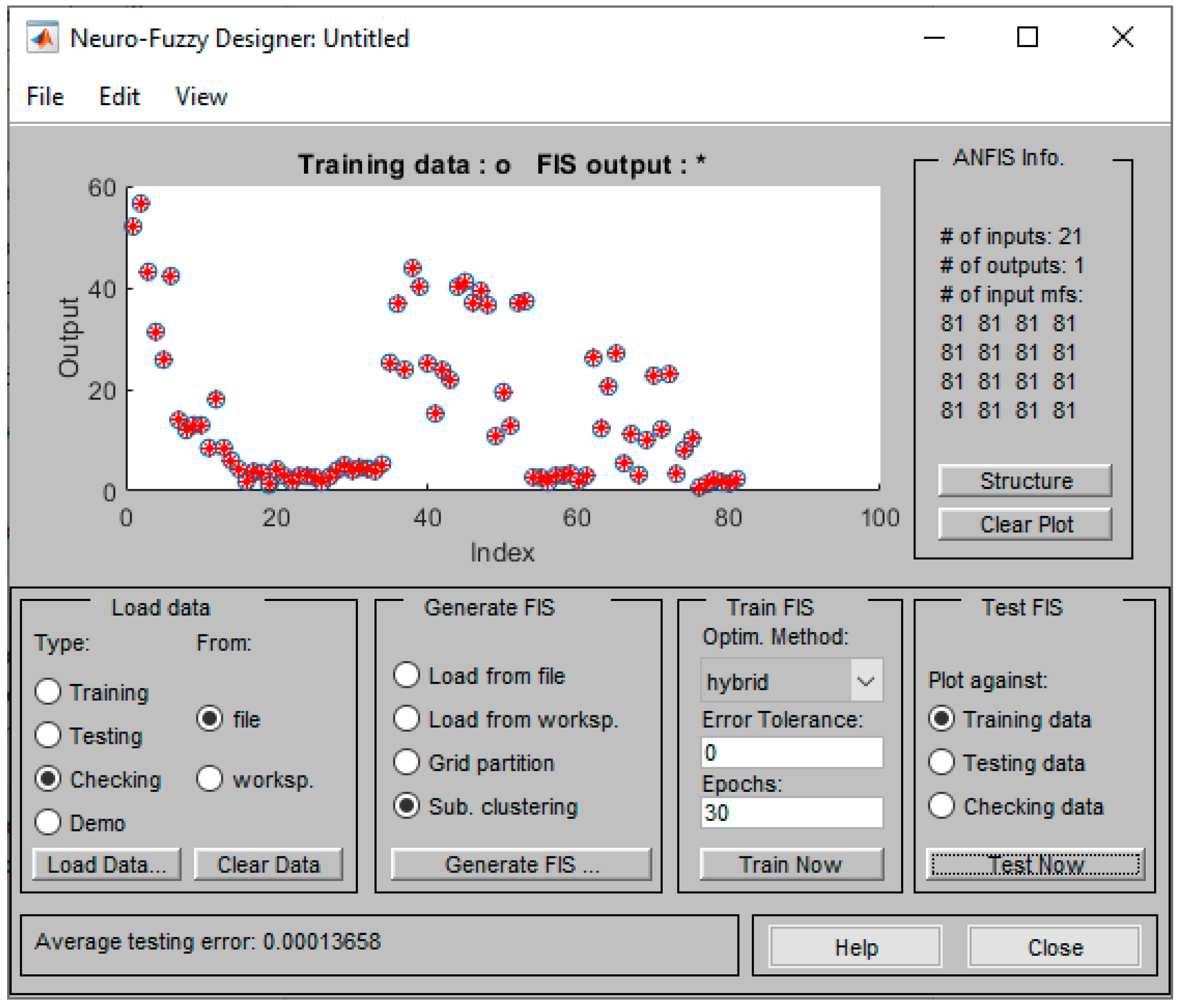
<p>Data for 21 input variables.</p> "> Figure 6
<p>Training process of the ANFIS.</p> "> Figure 7
<p>Testing error against training data (maximum stress).</p> "> Figure 8
<p>Error against checking data (maximum stress).</p> "> Figure 9
<p>ANFIS model structure.</p> "> Figure 10
<p>Data for 9 input variables.</p> "> Figure 11
<p>Training process of the ANFIS.</p> "> Figure 12
<p>Fuzzy rule activation.</p> "> Figure 13
<p>Surface plots against maximum stress between (<b>a</b>) Infill Pattern and Infill Percentage, (<b>b</b>) Infill Pattern and Layer Thickness, (<b>c</b>) Infill Percentage and Layer Thickness, and (<b>d</b>) Infill Percentage and Extruder Temperature.</p> "> Figure 14
<p>Comparison between experimental and predicted values against checking data (maximum stress).</p> "> Figure 15
<p>Comparison between experimental and predicted values against checking data (Young’s modulus).</p> "> Figure 16
<p>Comparison between experimental and predicted values against checking data (strain).</p> ">
Abstract
:1. Introduction
2. The Adaptive Neuro-Fuzzy Inference System (ANFIS)
- Rule 1: if (x is A1) and (y is B1), then (f1 = p1x + q1y + r1).
- Rule 2: if (x is A2) and (y is B2), then (f2 = p2x + q2y + r2).
3. Experimental Results and Validation
3.1. Gathering Experimental Data
3.2. The ANFIS Generic Model
3.3. The ANFIS Bending Model
4. Analysis of Model Performance
5. Conclusions
Author Contributions
Funding
Data Availability Statement
Conflicts of Interest
References
- Takagi, T.; Sugeno, M. Fuzzy identification of systems and its applications to modeling and control. IEEE Trans. Syst. Man Cybern. 1985, SMC-15, 116–132. [Google Scholar] [CrossRef]
- Jang, J.-S. ANFIS: Adaptive-network-based fuzzy inference system. IEEE Trans. Syst. Man Cybern. 1993, 23, 665–685. [Google Scholar] [CrossRef]
- ASTM F2792-12; Standard Terminology for Additive Manufacturing Technologies. ASTM International: West Conshohocken, PA, USA, 2012; Volume 1, p. 1.
- Ngo, T.D.; Kashani, A.; Imbalzano, G.; Nguyen, K.T.; Hui, D. Additive manufacturing (3D printing): A review of materials, methods, applications and challenges. Compos. Part B Eng. 2018, 143, 172–196. [Google Scholar] [CrossRef]
- Callı, M.; Albak, E.I.; Ozturk, F. Prediction and Optimization of the Design and Process Parameters of a Hybrid DED Product Using Artificial Intelligence. Appl. Sci. 2022, 12, 5027. [Google Scholar] [CrossRef]
- Ali, M.H.; Batai, S.; Sarbassov, D. 3D printing: A critical review of current development and future prospects. Rapid Prototyp. J. 2019, 25, 1108–1126. [Google Scholar] [CrossRef]
- Divjak, A.; Modrić, D.; Kovačić, I.; Cviljušac, V. Anisotropic Mechanical Properties of Materials in Stereolithographic Additive Manufacturing. Tech. Gaz. 2020, 27, 1748–1753. [Google Scholar]
- Khorasani, A.; Gibson, I.; Awan, U.S.; Ghaderi, A. The effect of SLM process parameters on density, hardness, tensile strength and surface quality of Ti-6Al-4V. Addit. Manuf. 2019, 25, 176–186. [Google Scholar] [CrossRef]
- Ramesh, M.; Panneerselvam, K. Mechanical investigation and optimization of parameter selection for Nylon material processed by FDM. Mater. Today Proc. 2021, 46, 9303–9307. [Google Scholar] [CrossRef]
- Abouelmajd, M.; Bahlaoui, A.; Arroub, I.; Zemzami, M.; Hmina, N.; Lagache, M.; Belhouideg, S. Experimental analysis and optimization of mechanical properties of FDM-processed polylactic acid using Taguchi design of experiment. Int. J. Simul. Multidiscip. Des. Optim. 2021, 12, 30. [Google Scholar] [CrossRef]
- Sagias, V.D.; Giannakopoulos, K.I.; Stergiou, C. Mechanical properties of 3D printed polymer specimens. Procedia Struct. Integr. 2018, 10, 85–90. [Google Scholar] [CrossRef]
- Polyzos, E.; Katalagarianakis, A.; Polyzos, D.; Van Hemelrijck, D.; Pyl, L. A multi-scale analytical methodology for the prediction of mechanical properties of 3D-printed materials with continuous fibres. Addit. Manuf. 2020, 36, 101394. [Google Scholar] [CrossRef]
- Kumar Mishra, P.; Senthil, P. Prediction of in-plane stiffness of multi-material 3D printed laminate parts fabricated by FDM process using CLT and its mechanical behaviour under tensile load. Mater. Today Commun. 2020, 23, 100955. [Google Scholar] [CrossRef]
- Yadav, D.; Chhabra, D.; Gupta, R.K.; Phogat, A.; Ahlawat, A. Modeling and analysis of significant process parameters of FDM 3D printer using ANFIS. Mater. Today Proc. 2020, 21, 1592–1604. [Google Scholar] [CrossRef]
- Mehrpouya, M.; Gisario, A.; Rahimzadeh, A.; Nematollahi, M.; Baghbaderani, K.S.; Elahinia, M. A prediction model for finding the optimal laser parameters in additive manufacturing of NiTi shape memory alloy. Int. J. Adv. Manuf. Technol. 2019, 105, 4691–4699. [Google Scholar] [CrossRef]
- Mohamed, O.A.; Xu, W. Comment about lack of sufficient data on “A prediction model for finding the optimal laser parameters in additive manufacturing of NiTi shape memory alloy” by Mehrpouya et al. [The International Journal of Advanced Manufacturing Technology 105.11 (2019): 4691–4699.]. Prog. Addit. Manuf. 2021, 7, 435–442. [Google Scholar]
- Dhar, A.R.; Gupta, D.; Roy, S.S. Development of a bi- directional multi- input- multioutput predictive model for the fused deposition modelling process using co-active adaptive neurofuzzy inference system, IOP Conference Series. Mater. Sci. Eng. 2021, 1136, 12007. [Google Scholar] [CrossRef]
- Abate, K.M.; Nazir, A.; Jeng, J.-Y. Design, optimization, and selective laser melting of vin tiles cellular structure-based hip implant. Int. J. Adv. Manuf. Technol. 2021, 112, 2037–2050. [Google Scholar] [CrossRef]
- Hu, Z.; Mahadevan, S. Uncertainty quantification in prediction of material properties during additive manufacturing. Scr. Mater. 2019, 135, 135–140. [Google Scholar] [CrossRef]
- Dev, S.; Srivastava, R. Experimental investigation and optimization of FDM process parameters for material and mechanical strength. Mater. Today Proc. 2017, 26, 1995–1999. [Google Scholar] [CrossRef]
- Zacharia, P.T. An Adaptive Neuro-fuzzy Inference System for Robot Handling Fabrics with Curved Edges towards Sewing. J. Intell. Robot Syst. 2010, 58, 193–209. [Google Scholar] [CrossRef]
- Azad, A.; Karami, H.; Farzin, S.; Saeedian, A.; Kashi, H.; Sayyahi, F. Prediction of Water Quality Parameters Using ANFIS Optimized by Intelligence Algorithms (Case Study: Gorganrood River). KSCE J. Civ. Eng. 2018, 22, 2206–2213. [Google Scholar] [CrossRef]
- Vakhshouri, B.; Nejadi, S. Prediction of compressive strength of self-compacting concrete by ANFIS models. Neurocomputing 2018, 280, 13–22. [Google Scholar] [CrossRef]
- Ly, H.-B.; Pham, B.T.; Dao, D.V.; Le, V.M.; Le, L.M.; Le, T.-T. Improvement of ANFIS Model for Prediction of Compressive Strength of Manufactured Sand Concrete. Appl. Sci. 2019, 9, 3841. [Google Scholar] [CrossRef]
- El-Hasnony, I.M.; Barakat, S.I.; Mostafa, R.R. Optimized ANFIS Model Using Hybrid Metaheuristic Algorithms for Parkinson’s Disease Prediction in IoT Environment. IEEE Access 2020, 8, 119252–119270. [Google Scholar] [CrossRef]
- Saleh, M.; Anwar, S.; Al-Ahmari, A.M.; AlFaify, A.Y. Prediction of Mechanical Properties for Carbon fiber/PLA Composite Lattice Structures Using Mathematical and ANFIS Models. Polymers 2023, 15, 1720. [Google Scholar] [CrossRef]
- ASTM D638-14; Standard Test Method for Tensile Properties of Plastics. ASTM International: West Conshohocken, PA, USA, 2014; Volume 1, p. 1.
- ASTM D695-15; Standard Test Method for Compressive Properties of Rigid Plastics. ASTM International: West Conshohocken, PA, USA, 2015; Volume 1, p. 1.
- ASTM D790-17; Standard Test Methods for Flexural Properties of Unreinforced and Reinforced Plastics and Electrical Insulating Materials. ASTM International: West Conshohocken, PA, USA, 2017; Volume 1, p. 1.
- ASTM D3039; Standard Test Method for Tensile Properties of Polymer Matrix Composite Materials. ASTM International: West Conshohocken, PA, USA, 2014; Volume 1, p. 1.
- ASTM D5279-21; Standard Test Method for Plastics: Dynamic Mechanical Properties: In Torsion. ASTM International: West Conshohocken, PA, USA, 2021; Volume 1, p. 1.
- ASTM D7791-17; Standard Test Method for Uniaxial Fatigue Properties of Plastics. ASTM International: West Conshohocken, PA, USA, 2017; Volume 1, p. 1.
- Srisaeng, P.; Baxter, G. Predicting Australia’s Domestic Airline Passenger Demand using an Anfis Approach. Transp. Telecommun. 2022, 23, 151–159. [Google Scholar] [CrossRef]


| Input/Factor | Number of Levels | Levels | Level Code |
|---|---|---|---|
| Input 1 */AM Technology | 4 discrete values | FFF/FDM | 1 |
| SLA | 2 | ||
| SLS | 3 | ||
| DED | 4 | ||
| Input 2 */Testing Method | 3 discrete values | Bending | 1 |
| Tensile | 2 | ||
| Torsion | 3 | ||
| Input 3 */Material | 8 discrete values | ABS + PLA | 1 |
| PLA | 2 | ||
| ABS | 3 | ||
| Resin Pro CR | 4 | ||
| ABS + | 5 | ||
| PETG | 6 | ||
| SUS316L | 7 | ||
| Ti | 8 | ||
| Input 4 */Infill Pattern | 6 discrete values | Rectilinear | 1 |
| Triangle | 2 | ||
| Honeycomb | 3 | ||
| Spiral | 4 | ||
| Cross | 5 | ||
| Diamond | 6 | ||
| Input 5 */Infill Percentage | Continuous (Range values) | Lower Level 0% Higher Level 100% | As input |
| Input 6 */Layer Thickness | Continuous (Range values) | Lower Level Higher Level | As input |
| Input 7 */Wall Thickness | Continuous (Range values) | Lower Level Higher Level | As input |
| Input 8/Speed | Continuous (Range values) | Lower Level Higher Level | As input |
| Input 9/Extruder Temperature | Continuous (Range values) | Lower Level Higher Level | As input |
| Input 10/Laser Power Ratio | Continuous (Range values) | Lower Level 0% Higher Level 100% | As input |
| Input 11/Bed Temperature | Continuous (Range values) | Lower Level 0 °C Higher Level 100 °C | As input |
| Input 12 */Position on Printer Platform | 6 | X | 1 |
| X + 30° | 2 | ||
| X + 45° | 3 | ||
| X + 60° | 4 | ||
| X + 90° | 5 | ||
| Y | 6 | ||
| Input 13 */Inclination against Printer Platform | 6 | On table | 1 |
| On table +30° | 2 | ||
| On table +45° | 3 | ||
| On table +60° | 4 | ||
| On table +90° | 5 | ||
| Vertical | 6 | ||
| Input 14 */Twist Angle around Center of Gravity axis | 2 | On table | 1 |
| On table +90° | 2 | ||
| Input 15 */Raster Angle | 7 | 0° | 1 |
| 90° | 2 | ||
| 0°/90° | 3 | ||
| 90°/0° | 4 | ||
| 30°/0°/−30° | 5 | ||
| 45°/−45° | 6 | ||
| 0°/120°/240° | 7 | ||
| Input 16/Layers for Altering Raster Angle (Block) | 7 | Per 1 layer | 1 |
| Per block—2 layers | 2 | ||
| Per block—3 layers | 3 | ||
| Per block—4 layers | 4 | ||
| Per block—5 layers | 5 | ||
| Per block—6 layers | 6 | ||
| Per block—7 layers | 7 | ||
| Input 17/Percentage of First Material | Continuous (Range values) | Lower Level 0% Higher Level 100% | As input |
| Input 18/Curing Time | Continuous (Range values) | Lower Level Higher Level | As input |
| Input 19/Curing Power | 4 discrete values | 0 | 0 |
| UT1 | 1 | ||
| UT2 | 2 | ||
| UT3 | 3 | ||
| Input 20/Layer Composition | 2 | Sandwich | 1 |
| Wave | 2 | ||
| Input 21/Cross-Section | 3 discrete values | Rectangle | 1 |
| Dogbone | 2 | ||
| Circle | 3 |
| S/N | Infill Pattern | Infill (%) | Layer Thickness (mm) | Speed (mm/s) | Temperature (°C) | Bed Temperature (°C) | Position on Bed | Twist Angle (°) | Inclination (°) |
|---|---|---|---|---|---|---|---|---|---|
| 1 | 2 | 50 | 0.07 | 50 | 200 | 60 | 1 | 1 | 5 |
| 2 | 2 | 75 | 0.07 | 50 | 200 | 60 | 3 | 1 | 5 |
| 3 | 3 | 100 | 0.18 | 50 | 200 | 60 | 5 | 1 | 7 |
| 4 | 2 | 75 | 0.18 | 50 | 200 | 60 | 5 | 1 | 5 |
| 5 | 2 | 100 | 0.18 | 50 | 200 | 60 | 1 | 1 | 5 |
| 6 | 3 | 50 | 0.18 | 50 | 200 | 60 | 3 | 1 | 7 |
| 7 | 2 | 100 | 0.3 | 50 | 200 | 60 | 3 | 1 | 5 |
| 8 | 2 | 50 | 0.3 | 50 | 200 | 60 | 5 | 1 | 5 |
| 9 | 3 | 75 | 0.3 | 50 | 200 | 60 | 1 | 1 | 7 |
| 10 | 1 | 60 | 0.18 | 25 | 215 | 55 | 1 | 1 | 6 |
| 11 | 3 | 60 | 0.18 | 38 | 215 | 55 | 5 | 1 | 7 |
| 12 | 2 | 60 | 0.18 | 50 | 215 | 55 | 1 | 5 | 5 |
| 13 | 3 | 60 | 0,18 | 25 | 230 | 55 | 1 | 5 | 7 |
| 14 | 2 | 60 | 0.18 | 38 | 230 | 55 | 1 | 1 | 5 |
| 15 | 1 | 60 | 0.18 | 50 | 230 | 55 | 5 | 1 | 6 |
| 16 | 2 | 60 | 0.18 | 25 | 245 | 55 | 5 | 1 | 5 |
| 17 | 1 | 60 | 0.18 | 38 | 245 | 55 | 1 | 5 | 6 |
| 18 | 3 | 60 | 0.18 | 50 | 245 | 55 | 1 | 1 | 7 |
| 19 | 1 | 15 | 0.18 | 25 | 215 | 55 | 1 | 1 | 6 |
| 20 | 3 | 15 | 0.18 | 38 | 215 | 55 | 5 | 1 | 7 |
| 21 | 2 | 15 | 0.18 | 50 | 215 | 55 | 1 | 5 | 5 |
| 22 | 3 | 15 | 0.18 | 25 | 230 | 55 | 1 | 5 | 7 |
| 23 | 2 | 15 | 0.18 | 38 | 230 | 55 | 1 | 1 | 5 |
| 24 | 1 | 15 | 0.18 | 50 | 230 | 55 | 5 | 1 | 6 |
| 25 | 2 | 15 | 0.18 | 25 | 245 | 55 | 5 | 1 | 5 |
| 26 | 1 | 15 | 0.18 | 37.5 | 245 | 55 | 1 | 5 | 6 |
| 27 | 3 | 15 | 0.18 | 50 | 245 | 55 | 1 | 1 | 7 |
| 28 | 1 | 15 | 0.18 | 25 | 180 | 25 | 1 | 1 | 6 |
| 29 | 3 | 15 | 0.18 | 38 | 180 | 25 | 5 | 1 | 7 |
| 30 | 2 | 15 | 0.18 | 50 | 180 | 25 | 1 | 5 | 5 |
| 31 | 3 | 15 | 0.18 | 25 | 195 | 25 | 1 | 5 | 7 |
| 32 | 2 | 15 | 0.18 | 37.5 | 195 | 25 | 1 | 1 | 5 |
| 33 | 1 | 15 | 0.18 | 50 | 195 | 25 | 5 | 1 | 6 |
| 34 | 2 | 15 | 0.18 | 25 | 210 | 25 | 5 | 1 | 5 |
| 35 | 1 | 15 | 0.18 | 38 | 210 | 25 | 1 | 5 | 6 |
| 36 | 3 | 15 | 0.18 | 50 | 210 | 25 | 1 | 1 | 7 |
| 37 | 1 | 60 | 0.18 | 25 | 180 | 60 | 1 | 1 | 6 |
| 38 | 3 | 60 | 0.18 | 37.5 | 180 | 60 | 5 | 1 | 7 |
| 39 | 2 | 60 | 0.18 | 50 | 180 | 60 | 1 | 5 | 5 |
| 40 | 3 | 60 | 0.18 | 25 | 195 | 60 | 1 | 5 | 7 |
| 41 | 2 | 60 | 0.18 | 37.5 | 195 | 60 | 1 | 1 | 5 |
| 42 | 1 | 60 | 0.18 | 50 | 195 | 60 | 5 | 1 | 6 |
| 43 | 2 | 60 | 0.18 | 25 | 210 | 60 | 5 | 1 | 5 |
| 44 | 1 | 60 | 0.18 | 37.5 | 210 | 60 | 1 | 5 | 6 |
| 45 | 3 | 60 | 0.18 | 50 | 210 | 60 | 1 | 1 | 7 |
| S/N | Stress Average (MPa) | Stress Standard Deviation | Strain Average (%) | Strain Standard Deviation | Young’s Modulus (GPa) |
|---|---|---|---|---|---|
| 1 | 14.00 | 1.10 | 5.80 | 0.62 | 6.03 |
| 2 | 12.00 | 0.67 | 7.00 | 0.52 | 4.29 |
| 3 | 13.00 | 0.66 | 5.00 | 0.71 | 6.50 |
| 4 | 13.00 | 0.60 | 8.50 | 0.72 | 3.82 |
| 5 | 8.50 | 0.41 | 5.00 | 0.45 | 4.25 |
| 6 | 18.00 | 0.62 | 6.00 | 0.77 | 7.50 |
| 7 | 8.50 | 0.34 | 5.00 | 0.24 | 4.25 |
| 8 | 8.00 | 0.78 | 2.50 | 0.49 | 8.00 |
| 9 | 6.00 | 0.73 | 4.50 | 0.58 | 3.33 |
| 10 | 3.20 | 0.45 | 2.50 | 0.42 | 3.20 |
| 11 | 4.00 | 0.41 | 3.40 | 0.64 | 3.02 |
| 12 | 1.00 | 0.35 | 0.82 | 0.68 | 3.20 |
| 13 | 2.00 | 0.35 | 1.50 | 0.49 | 3.59 |
| 14 | 3.00 | 0.42 | 2.45 | 0.74 | 3.38 |
| 15 | 4.00 | 0.42 | 3.00 | 0.66 | 3.76 |
| 16 | 2.00 | 0.57 | 1.50 | 0.62 | 3.85 |
| 17 | 1.50 | 0.24 | 1.00 | 0.42 | 4.43 |
| 18 | 4.00 | 0.44 | 3.45 | 0.32 | 3.51 |
| 19 | 3.75 | 0.70 | 2.50 | 0.64 | 4.64 |
| 20 | 4.00 | 0.55 | 2.50 | 0.47 | 5.06 |
| 21 | 2.50 | 0.47 | 1.60 | 0.56 | 5.05 |
| 22 | 2.00 | 0.23 | 1.20 | 0.38 | 5.51 |
| 23 | 4.00 | 0.40 | 2.60 | 0.44 | 5.20 |
| 24 | 3.00 | 0.51 | 1.95 | 0.59 | 5.31 |
| 25 | 4.00 | 0.48 | 2.50 | 0.57 | 5.64 |
| 26 | 1.50 | 0.33 | 1.05 | 0.47 | 5.14 |
| 27 | 4.00 | 0.53 | 2.55 | 0.54 | 5.77 |
| 28 | 4.08 | 0.75 | 4.78 | 0.49 | 2.14 |
| 29 | 5.09 | 0.62 | 4.51 | 0.77 | 2.82 |
| 30 | 4.03 | 0.80 | 1.86 | 0.83 | 5.41 |
| 31 | 4.27 | 0.52 | 1.85 | 0.42 | 5.77 |
| 32 | 4.53 | 0.79 | 4.44 | 0.55 | 2.55 |
| 33 | 4.45 | 0.67 | 4.33 | 0.65 | 2.57 |
| 34 | 3.96 | 1.04 | 4.28 | 0.98 | 2.32 |
| 35 | 3.13 | 0.75 | 1.90 | 0.53 | 4.12 |
| 36 | 5.29 | 0.54 | 4.70 | 0.62 | 2.81 |
| 37 | 2.73 | 0.83 | 5.18 | 0.92 | 0.74 |
| 38 | 2.64 | 0.76 | 3.75 | 0.81 | 0.99 |
| 39 | 2.66 | 0.48 | 2.77 | 0.39 | 1.35 |
| 40 | 1.69 | 0.52 | 2.80 | 0.64 | 0.85 |
| 41 | 3.03 | 0.62 | 4.63 | 0.52 | 0.92 |
| 42 | 2.98 | 0.62 | 4.80 | 0.58 | 0.87 |
| 43 | 3.36 | 0.83 | 3.82 | 0.78 | 1.24 |
| 44 | 1.98 | 0.40 | 2.53 | 0.37 | 1.10 |
| 45 | 3.01 | 0.70 | 4.90 | 0.69 | 0.86 |
| Infill Pattern | Infill (%) | Layer Thickness (mm) | Speed (mm/s) | Temperature (°C) | Bed Temperature (°C) | Position on Bed | Twist angle (°) | Inclination (°) |
|---|---|---|---|---|---|---|---|---|
| 2 | 50 | 0.1 | 50 | 200 | 60 | 1 | 1 | 5 |
| 2 | 75 | 0.1 | 50 | 200 | 60 | 3 | 1 | 5 |
| 3 | 100 | 0.1 | 50 | 200 | 60 | 5 | 1 | 7 |
| 2 | 75 | 0.2 | 50 | 200 | 60 | 5 | 1 | 5 |
| 2 | 100 | 0.2 | 50 | 200 | 60 | 1 | 1 | 5 |
| 3 | 50 | 0.2 | 50 | 200 | 60 | 3 | 1 | 7 |
| 2 | 100 | 0.3 | 50 | 200 | 60 | 3 | 1 | 5 |
| 2 | 50 | 0.3 | 50 | 200 | 60 | 5 | 1 | 5 |
| 3 | 75 | 0.3 | 50 | 200 | 60 | 1 | 1 | 7 |
Disclaimer/Publisher’s Note: The statements, opinions and data contained in all publications are solely those of the individual author(s) and contributor(s) and not of MDPI and/or the editor(s). MDPI and/or the editor(s) disclaim responsibility for any injury to people or property resulting from any ideas, methods, instructions or products referred to in the content. |
© 2024 by the authors. Licensee MDPI, Basel, Switzerland. This article is an open access article distributed under the terms and conditions of the Creative Commons Attribution (CC BY) license (https://creativecommons.org/licenses/by/4.0/).
Share and Cite
Sagias, V.D.; Zacharia, P.; Tempeloudis, A.; Stergiou, C. Adaptive Neuro-Fuzzy Inference System-Based Predictive Modeling of Mechanical Properties in Additive Manufacturing. Machines 2024, 12, 523. https://doi.org/10.3390/machines12080523
Sagias VD, Zacharia P, Tempeloudis A, Stergiou C. Adaptive Neuro-Fuzzy Inference System-Based Predictive Modeling of Mechanical Properties in Additive Manufacturing. Machines. 2024; 12(8):523. https://doi.org/10.3390/machines12080523
Chicago/Turabian StyleSagias, Vasileios D., Paraskevi Zacharia, Athanasios Tempeloudis, and Constantinos Stergiou. 2024. "Adaptive Neuro-Fuzzy Inference System-Based Predictive Modeling of Mechanical Properties in Additive Manufacturing" Machines 12, no. 8: 523. https://doi.org/10.3390/machines12080523