ECFI: Asynchronous Control Flow Integrity for
Programmable Logic Controllers
Ali Abbasi∗
Thorsten Holz
University of Twente
The Netherlands
a.abbasi@utwente.nl
Ruhr-Universität Bochum
Germany
thorsten.holz@rub.de
Emmanuele Zambon
Sandro Etalle2
SecurityMatters B.V.
The Netherlands
emmanuele.zambon@secmatters.com
Eindhoven University of Technology
The Netherlands
s.etalle@tue.nl
ABSTRACT
1
Programmable Logic Controllers (PLCs) are a family of embedded
devices that are being used to control physical processes in critical infrastructures. Similar to other embedded devices, PLCs are
vulnerable to memory corruption and control-flow hijacking attacks. Because PLCs are being used for critical control applications,
compromised PLCs constitute a significant security and safety risk.
In this paper, we introduce a novel, PLC-compatible control-flow
integrity (CFI) mechanism named ECFI to protect such devices from
control-flow hijacking attacks. Our CFI approach is the first system
for real-time PLCs and considers the runtime operation of the PLC
as the highest priority. We implemented a prototype of ECFI and
tested it in a real-world industrial PLC against different kinds of
attacks. Our performance evaluation demonstrates that ECFI is an
efficient, non-intrusive CFI solution that does not impose notable
performance overhead and maintains the timeliness of PLC runtime
operations, a critical property for this kind of embedded systems.
Control-flow hijacking represents one of the major attack vectors
against computer systems in the last two decades. Given the impact
that control-flow attacks had on general-purpose computers [18],
most operating systems adopted the Executable Space Protection
(ESP, also known as NX, W ⊕ X , or DEP) mechanism [10, 24] together with Address Space Layout Randomization (ASLR). To overcome these exploit mitigation approaches, a new exploitation technique named return-oriented programming (ROP) [46] was proposed,
which allows an attacker to circumvent ESP.
To address this problem, Abadi et al. suggested the concept of
control-flow integrity (CFI) as a general defense against ROP attacks [1]. CFI ensures that program execution only passes through
approved execution paths taken from the software’s control-flow
graph (CFG). To achieve this, at each indirect jump/call and return instruction, the destination address is checked to determine
whether it follows a valid path in the CFG [7]. Following Abadi
et al. [1] various researchers suggested different CFI policies and
implementations for general-purpose computers [9, 49, 50, 52, 54].
Similar to general-purpose computers, an attacker can use ROP
and ROP-like techniques such as Ret2ZP [21] to overcome exploit
mitigation mechanisms in embedded systems. However, embedded
systems are a lot more diverse in terms of resources, availability, and
thus CFI system requirements and specifications are different with
respect to general-purpose computers. Because of this diversity,
only few CFI approaches were proposed for embedded platforms
such as mobile devices [12, 38].
Among embedded systems, a family of industrial devices named
Programmable Logic Controllers (PLCs) plays a major role in critical infrastructures. PLCs are real-time embedded systems which
control physical industrial processes via their I/O interfaces. Due
to their sensitive role in controlling industrial processes, successful
exploitation of a PLC can affect the physical world and, as a result,
can have severe consequences. Despite their importance regarding
the safety and security of industrial processes, PLCs are as vulnerable to control-flow attacks as (most) other systems [22]. Similar
to general-purpose computers, control-flow hijacking attacks such
as ROP are one of the key techniques that an attacker can use to
obtain system level access to a given PLC. Due to lack of protection
mechanisms inside a PLC, getting system level access to it can pave
the way for attackers to silently manipulate industrial processes
KEYWORDS
PLC, Real-Time, Industrial Control System (ICS), Embedded System
ACM Reference format:
Ali Abbasi, Thorsten Holz, Emmanuele Zambon, and Sandro Etalle. 2017.
ECFI: Asynchronous Control Flow Integrity for Programmable Logic Controllers. In Proceedings of ACSAC 2017, San Juan, PR, USA, December 4ś8,
2017, 12 pages.
https://doi.org/10.1145/3134600.3134618
∗ Also
2 Also
with Ruhr-Universität Bochum.
with Services, Cyber Security and Safety Group, University of Twente.
Permission to make digital or hard copies of all or part of this work for personal or
classroom use is granted without fee provided that copies are not made or distributed
for profit or commercial advantage and that copies bear this notice and the full citation
on the first page. Copyrights for components of this work owned by others than the
author(s) must be honored. Abstracting with credit is permitted. To copy otherwise, or
republish, to post on servers or to redistribute to lists, requires prior specific permission
and/or a fee. Request permissions from permissions@acm.org.
ACSAC 2017, December 4ś8, 2017, San Juan, PR, USA
© 2017 Copyright held by the owner/author(s). Publication rights licensed to Association for Computing Machinery.
ACM ISBN 978-1-4503-5345-8/17/12. . . $15.00
https://doi.org/10.1145/3134600.3134618
INTRODUCTION
�ACSAC 2017, December 4–8, 2017, San Juan, PR, USA
without being detected using techniques such as the Pin Control Attack [2]. Despite such attack vectors, to the best of our knowledge,
no CFI solution for PLCs has been devised. Existing CFI approaches
for other non-critical embedded systems or general-purpose computers cannot work for a PLC: As described in the NIST (National
Institute of Standards and Technology) 800-82 guideline, any security measures for Industrial Control Systems (ICS), including PLCs,
must also consider availability and real-time requirements of the
system [48]. To the best of our knowledge, no CFI system to date
considers availability and timeliness (real-time) requirements of
the PLC.
In this paper, we present the design and implementation of ECFI,
the first control-flow verification system for environments where
availability and hard real-time systems are crucial. To address its
environmental requirements, ECFI considers the availability and
timeliness of the PLC more important than the security of it. ECFI
is a fine-grained CFI approach that protects both forward edges
and backward edges of the control-flow graph. ECFI consists of
a non-conditional simple instrumentation code and a lock-free
asynchronous shadow stack which is implemented as a ring buffer,
combined with a checking routine. This architecture allows the PLC
OS to schedule runtime CFI checks according to the PLC’s real-time
constraints. Our prototype implementation of this concept supports
the ARM architecture. We especially focus on ARM-based devices
since a large share of PLCs use ARM processors [44].
To test ECFI, we implemented it in a real-world industrial PLC,
running a Real-Time Operating System (RTOS). We use ECFI to
protect a PLC runtime application which reads I/O inputs, executes
PLC control logic, updates the outputs, and provides a Modbus
TCP server for the SCADA server. Besides respecting real-time
constraints, our prototype implementation induces a moderate 1.5%
CPU overhead.
Maintaining the availability and timeliness requirement of the
PLC comes at a cost. In our case, to preserve the real-time properties of the PLC, we devoted the CFI-checker to a separate process
that has lower priority. We also had to make our shadow stack
overwrite-able to avoid priority inversion, which is a common issue
for real-time systems [42]. Using these features of ECFI, an attacker
can force a process to "starve" by keeping the CPU busy (e.g., by
using a DoS attack) and then overwrite the shadow stack with normal values that do not raise any alert. However, we use inherited
features of the real-time systems to design a strategy that mitigates
this attack possibility. In a real-time system, the range of consumed
CPU cycles of the tasks is both small and predictable. Thus ECFI
monitors the CPU cycles consumed per PLC scan cycle to detect
an attack against the shadow stack. To evaluate this strategy, we
construct a ROP chain to attack our shadow stack and overwrite
the control-flow meta-data with fake but acceptable values. In the
same time, we executed a DoS attack against the PLC which consumed all CPU resources of the device. However, our prototype
implementation was still able to detect the shadow stack overwrite
and raise an alert for this attack.
In summary, the contributions of this paper are as follows:
• First CFI approach for PLCs: ECFI is the first CFI enforcement
system that was designed for real-world industrial PLCs.
Ali Abbasi, Thorsten Holz, Emmanuele Zambon, and Sandro Etalle
Our CFI approach has limited CPU overhead and no I/O
performance impact.
• Hard real-time compatibility: the main objective of a PLC is
to control physical processes with real-time constraints. The
priority of applications running inside a PLC is thus subject
to the PLC’s ability to run its primary tasks: updating I/Os
and running the control logic on time. ECFI, to the best of
our knowledge, is the first CFI approach that considers the
real-time requirements of the PLC runtime.
2
BACKGROUND
Before diving into the technical details of our approach, we briefly
discuss the necessary background information needed to understand the rest of the paper.
2.1
Programmable Logic Controllers
Programmable Logic Controllers (PLCs) are a family of embedded
devices that are used in critical industrial environments. Usually,
these environments mandate real-time control over an industrial
process. Failing to execute one or multiple I/O operations in a timely
manner may result in the failure of an industrial process, which
leads to unacceptable consequences. To overcome this problem, the
majority of PLCs are equipped with RTOS to execute their tasks in
a predictable manner.
For example, a PLC which operators use in a sewer network
must be able to react to the changes in the water level due to rain
in real-time. In a power plant, a PLC-like device must react to an
out-of-phase generator by controlling a generator breaker on a
millisecond scale.
Generally speaking, a PLC runs a software called the runtime
that controls its primary task, I/O operations. The runtime software
interprets or executes another code known as the control logic. The
control logic is a compiled form of the PLC’s programming language,
such as Structured Text, Function Block Diagram (FBD), or ladder
logic. FBDs and ladder logic are graphical programming languages
that describe the control logic of a given industrial process. The PLC
runtime usually prepares the control logic execution by scanning
the inputs and storing it in the variable table and then updating the
outputs. A sequence consisting of reading the inputs, executing the
control logic code, and updating the outputs is called the program
scan cycle. The PLC program scan is an infinite loop and runs
indefinitely. The variable table is a virtual table that contains all the
variables needed by the control logic: setpoints, counters, timers,
inputs, and outputs. During the program scan cycle, every change
in the I/O of the PLC is ignored until the next program scan cycle.
Figure 1 depicts the PLC runtime operation, the running of the
logic, and its interaction with the I/O.
One of the most common architectures used for PLCs is the
ARM architecture [44]. For example, various models of PLCs manufactured by vendors such as Allen-Bradley, Schneider Electric,
Honeywell, and WAGO PLCs are using the ARM architecture [44].
2.2
PLC Logic
There are two types of PLC logic: bytecode based and binary based.
In bytecode-based logic, the bytecode will get executed by the PLC
runtime with a Just-in-Time (JIT) compiler. An example of PLC
�ECFI: Asynchronous Control Flow Integrity for Programmable Logic Controllers
PLC Runtime
Logic
Variable Table
(VT)
Logic
Program
Program Scan
Read Inputs
Update
Outputs
Read/Write
VT
Inputs from
I/O
Set Points
Output to I/O
(Pin 22 = 001)
Write Output value
Virtually Mapped I/O
Address
0XBEFFFFFF
Value
001
Figure 1: Overview of PLC runtime operation in a program
scan cycle and its interaction with the I/O.
runtime which executes bytecode is the Siemens S7 series PLC
runtime. In binary-based logic, the logic program gets converted to
a binary first and then gets uploaded to the PLC. The PLC runtime
then executes the binary inside the PLC. An example of PLC runtime that executes executable is the 3S Codesys runtime, which is
currently used by more than 261 PLC vendors [14] including ABB,
Schneider-Electric, Beckhoff, Wago, Mitsubishi, and Bosch. In this
paper, we only focus on PLCs which are using binary logic in their
runtime. However, a similar approach employed in RockJIT [34]
can also be used to protect bytecode based PLC logic.
2.3
Existing Attacks and Defenses against PLCs
For an attacker, the ultimate objective when attacking an industrial control network is to manipulate the physical process without
being detected by advanced intrusion detection systems (IDS) or
plant operators [3]. As described by Abbasi et. al. [2] there are
three family of attacks against PLCs named as Firmware modification attacks (FMA) [6, 37], Configuration manipulation attacks (CMA) [29, 30] and Control-flow attacks (CFA) [22, 22]. For
FMA [5, 16] and CMA [6, 28] attacks in the PLC, at least one tailored
defensive solution exists. Although several techniques have been
proposed to detect or prevent control-flow attacks on general IT
systems or generic embedded systems [4], currently, no research
suggests a control-flow detection mechanism specifically designed
for real-time PLCs.
2.4
Attacker Model
Since a PLC is a computer device which is mostly being used in Operational Technology (OT) domain of an Industrial Control System
(ICS), we can not just describe our attacker model in the traditional
ACSAC 2017, December 4–8, 2017, San Juan, PR, USA
IT domain which is usual in other CFI papers. Instead, we will divide our attacker model to two parts. We first describe our attacker
model for the OT and then IT domain.
2.4.1 OT Attacker Model: In this paper, we do not consider
adversaries that do not understand the behavior of the target process and do not want to manipulate the physical process carefully.
An adversary who wants to cause a naïve attack can simply achieve
her objective by overwriting the return address of a memory corruption vulnerability to a non-valid memory address and thus terminate the PLC runtime (DoS attack), causing the PLC to lose its
control of the physical process. No CFI system can cope with such
attack. Instead, in our attacker model, we assume an adversary
whose objective is to exploit the PLC to manipulate an industrial
process carefully. We believe that in the majority of attacks which
manipulate the physical process there will be a delay between infection of the PLC and manipulation of the physical process. This
delay is due to two reasons:
• Delay caused by infecting multiple types of equipment: once
an attacker gets access to an industrial network, depending
on the complexity of the physical process, she might need
to infect more than one industrial equipment such as PLC
to be able to manipulate the process. Therefore, the attacker
in this step will infect multiple devices before executing
the attack. Indeed, looking at the German steel mill cyber
attack reported by BSI (Bundesamt fur Sicherheit in der
Informationstechnik) [19, 25] and the Stuxnet [17] attackers
had to infect multiple devices (e.g., infecting both operation
PLC and fail-safe PLCs) before executing the attack.
• Delay due to process and I/O mapping: as described by McLaughlin et al. [29] even if an attacker completely takes control
of a PLC, she still faces two challenges. Firstly, the attacker
needs to gain knowledge about the control system behavior, and secondly, the attacker needs to recover semantics
of PLC memory locations that are mapped to physical I/O
to execute process manipulation. SABOT [29] can generate such payload and retrieve the mapping of the system
automatically assuming that attacker is fully aware of the
control system behavior. However, it needs time to process
and model the PLC behavior to be able to recover the mapping of the I/O interfaces and the PLC memory. Looking into
the Stuxnet case [17] again, the attackers were recording the
process control data for weeks after infection before they
start their actual process manipulation. A similar technique
(infect, wait, then manipulate) was used in Ukrainian power
grid blackout [8, 51].
2.4.2 IT Attacker Model: In this paper, we assume an attacker
who tries to hijack the control flow of a vulnerable hard real-time
PLC runtime using a ROP attack. We also assume that the PLC has
a modern RTOS with MMU support and is equipped with exploit
mitigation techniques such as ASLR, PIE, NX, and stack cookies, but
the attacker can bypass such defenses using an information-leak
primitive within the PLC runtime. Our CFI approach must be able
to detect any attempts of arbitrary code execution in a protected
application/service inside the PLC according to the defined scope
of the attack.
�ACSAC 2017, December 4–8, 2017, San Juan, PR, USA
3
Ali Abbasi, Thorsten Holz, Emmanuele Zambon, and Sandro Etalle
ECFI DESIGN
In the following, we present ECFI, our CFI enforcement system that
was designed and tested for PLCs.
3.1
Application
Source
Code
1
Application
Assembly
Code
2
Design Considerations for CFI in a PLC
Generally speaking, we can divide any protection mechanism into
active and passive forms. In the case of active protection mechanism,
the system will prevent the attack upon detection, while in the case
of a passive protection, the system raises an alert notifying about
the attack. In a CFI context for a PLC, active protection means that
the PLC runtime gets terminated upon a control-flow violation.
Passive detection in a PLC means that the CFI system raises an
alert upon a control-flow violation without any intervention. In the
following, we describe the parameters for designing a CFI solution
for PLCs:
Availability: to the best of our knowledge, all existing CFI implementations for embedded systems act as an active protection
system and if deployed in a PLC, terminating the PLC runtime
process upon control-flow hijacking would violate the availability
requirement of the PLC. In case of a false positive, an active protection system could hence cause a dumb disruption in a critical
infrastructure. However, one can rightfully argue that this is an
engineering issue and existing CFI systems can get fixed to act as a
passive protection system. To maintain the availability of the PLC,
ECFI serves as a passive protection system. While one can use ECFI
as an active protection system (by activating a related flag in the
checker), we do not enable it by default except the process requires
such an intrusive approach in an industrial environment.
Timeliness: real-time properties of a PLC is measured by predicting its execution time. Any CFI implementation that uses conditional branches, exception handlers, or loops can significantly
complicate the predictability of the execution time [41] in the PLC
program. To address this issue, a CFI approach must then perform a complex Worst-case Execution Time analysis. Otherwise,
the entire PLC software must be considered as unpredictable and
thus non-real-time, which is unacceptable. Unfortunately, no CFI
system provides such an analysis. Looking at the two existing wellknown CFI system for embedded systems named as MoCFI [12]
and CFR [38], shows that they use conditional branches [12, 38],
exception handler [12] and loops [38], which makes them unsuitable for a real-time PLC. ECFI does not use such instructions in its
instrumentation code.
Additionally, in existing CFI systems, the CFG verification mechanism is always part of the application and is not running in a
separate process. Due to the usage of conditional branches, exception handlers and conditional loops in the CFI, the PLC process
might also face the priority inversion problem [27] which is not
acceptable in real-time systems. The priority inversion is a problem
where a lower priority task in the software locks the resources or
execution of a higher priority task. As a result, the higher priority
task can experience an additional delay since the lower priority
has locked the resource up to the end of its execution. As a result,
a higher priority task will fail to execute its tasks in a predictable
manner. In real-time systems, a priority inversion should not happen. For a hard real-time PLC, the highest priority task is the actual
Instrumented
Application
Generate
CFG
CFG
4
Compile
Instrumentation
Instructions
Injecting
Instrumentation
Instructions
(CPI Module)
3
Ring Buffer
Shadow Stack
CFI Checker and
CPU Cycles
Monitoring
5
Figure 2: Simplified design of ECFI.
control program which executes the process (so-called program
scan cycle), while the lower priority task is the CFG verification.
With the traditional approaches, the PLC functions call/return must
wait until CFG verification system decide whether a control-flow
violation occurred or not. ECFI separates the CFG verification process from the protected runtime to avoid the complex execution
time analysis and prevent the priority inversion problem.
As mentioned before, ECFI considers the availability and timeliness requirement of the real-time PLC more important than the
security of it and thus makes compromises to address them.
3.2
General Principle of Operation
ECFI is a compiler-level CFI approach which injects instrumentation
instructions into the existing assembly code of the application
during the compilation phase. Figure 2 depicts a high-level overview
of the architecture of ECFI. The system consists of five modules:
(1) Instrumentation instructions to copy the real control-flow
data to the ring buffer.
(2) Code Parser-Injector (CPI), which parses the application’s
assembly code and adds instrumentation instructions to the
code.
(3) Ring buffer shadow stack that stores the runtime controlflow data.
(4) Control-flow graph that contains the correct execution path
of the application.
(5) Checker that verifies the control-flow information with the
CFG.
3.3
Instrumentation Instructions
The instrumentation instructions are a set of instructions which
copy the control-flow values to the ring buffer shadow stack. Our
code does not contain any conditional branch, loop, function pointer,
direct and indirect recursion, or exception handler. Since a PLC
runtime must be real-time, it is essential to have instrumentation
instructions that have predictable worst execution time. Therefore,
we made the computation of Worst-Case Execution Time (WCET)
in our instrumentation instructions feasible by following the recommendations made by Puschner et al. [41] for real-time applications
using CPU cycles.
�ECFI: Asynchronous Control Flow Integrity for Programmable Logic Controllers
Hard Real-Time PLC
Runtime
Non-Realtime
CFI
Verification
Write
R3, 0x90
to buffer
Read Multiple
When Resource
Available
Instrument (ID=0x90)
BLX R3
(Indirect Function Call)
Instrument (ID=0x86)
Write
[LR], 0x86
to buffer
BX R14/POP {R7,PC}
( Function Return)
Ring Buffer
Shadow
Stack
CPU Registers
R3
LR
0x1053C (Func1)
0x76beffaa
Read(0x1053C, 0x90,
0x104b8, 0x86)
Verify
Control
Flow
Stack
0x76beffaa 0x104b8 (main+0x48)
....
....
Figure 3: Ring buffer shadow stack design.
3.4
Instrumentation Injector
There are two locations in the execution flow of the ARM-based
application where an attacker can hijack the control flow. First, by
modifying the register value in the indirect function call (indirect
branches). Second, by modifying return address values right before
the return instruction (returns). Therefore, these two locations must
be instrumented, and the program execution flow information must
be passed to the ring buffer shadow stack before the actual call or
branch occurs.
The instrumentation injector will parse the assembly code of
the application and insert the instrumentation instructions to those
two locations:
Indirect Branches. In the ARM architecture, indirect function
calls are performed by the BLX instruction. The BLX instruction
calls a value in a register (e.g., BLX r3) where the register value is
dynamically calculated at runtime.
The indirect branch destination will be passed to our shadow
stack for verification (see Figure 3). We do not control the destination of direct branches since the direct branches have a hard-coded
destination in the application binary, and it would be impossible for
an attacker to hijack the control flow right before direct branches.
Note that we consider all instructions which directly modify the
Program Counter (PC) in ARM architecture as indirect branches
(e.g., LDR PC, RegX).
Returns. Another way to hijack control flow on the ARM architecture is when the function or the basic block (BB) returns. The
return address will be pushed onto the stack and will be recovered
at the end of function epilogue. If an attacker manages to overwrite
the stack value that holds the return address, she can obtain control over the execution flow of the PLC runtime. Therefore, ECFI
monitors all function returns in the PLC.
3.5
The Ring Buffer and Checker Design
To ensure the PLC runtime remains real-time, we need to design
a protection system that does not disrupt the real-time execution
of the PLC runtime. We designed our ring buffer shadow stack
which is a shared memory in a way which is lock-free and asynchronous. This design makes it possible for the RTOS to halt the
ECFI system whenever another important PLC task such as I/O
operations needs resources, while the ECFI checker process runs on
ACSAC 2017, December 4–8, 2017, San Juan, PR, USA
a lower priority. The ring buffer shadow stack is a fixed-size shared
memory region that is accessible to the real-time application and
control-flow checker subsystem. Whenever the CPU executes an
instrumented BB, the BB writes the destination or return address,
combined with their respective identification number, to the ring
buffer. In this paper, we call the identification number HotsiteID.
Finally, the ring buffer acts as a shared memory which is accessible
to both checker application and the protected PLC runtime. The
ring buffer is created with group permission (via S_IWGRP and
S_IRGRP).
Checker Application. The checker application is a non-real-time
program running as a separate process with a lower priority (compared to the protected PLC runtime application). Instead of invoking
the instrumentation instruction every time it writes to the shadow
stack, the checker will wait for the operating system to allocate
system resources. The checker then reads the data from the shadow
stack, and copies the data to its dynamic memory, and evaluates
the control-flow data using the CFG. By default, the checker application will not terminate the PLC runtime upon the detection
of a control-flow hijacking attack (while we have a flag in ECFI to
kill the process). Instead, it generates a log regarding the attack,
which a plant operator can read. To securely store the log files, the
checker application runs under a different user (while being in the
same user group as the PLC runtime) and the log files are only
write/readable by that user and therefore, not accessible by the PLC
runtime user.
Lock-Free Design. There are two features in our shadow stack
which make our approach real-time friendly. First, during write
or read operations, no locking is enforced on the shadow stack.
Consequently, while the shadow stack is being written, the checker
application can read it at the same time. By not locking the shadow
stack, we avoid the common priority inversion problem in real-time
systems caused by resource/memory locking.
Second, our shadow stack allows memory overwrite. This means
that if there are no resources available for the checker to execute
and the shadow stack gets full, the real-time application is allowed
to overwrite previously written control-flow data. Therefore, at the
end of the ring buffer, there is no forced call of the checker to free
the shadow stack (by reading its values). However, this feature can
be used by the attacker to overwrite the ring buffer.
Ring Buffer Protection. An attacker may want to take advantage
of the ring buffer lock-free mechanism for attack concealment.
For that she can, for example, perform a Denial of Service (DoS)
attack against the PLC to increase its CPU usage. Once the CPU
usage increases, the checker application less frequently verifies
the control flow of the PLC runtime (or halts until resources are
available again). In the meantime, the attacker can exploit the ring
buffer by overwriting it with fake values. However, since PLC is a
hard real-time machine, the attacker’s capabilities can be limited
by monitoring the number of CPU cycles performed in every PLC
program scan cycle. Also for an attacker to remain stealth, the DoS
attack should not be prolonged, since DoS attacks would diminish
the PLC’s ability to update I/O values on time. Anomalous behavior
of PLC I/O might be detected by the PLC operator. Therefore, the
�ACSAC 2017, December 4–8, 2017, San Juan, PR, USA
attacker can only execute its DoS attack during a short period, e.g.,
for few seconds.
As described in Section 2, PLCs executes control logic program in
a program scan cycle. Due to real-time nature of PLC runtime, the
number of CPU cycles it uses in every program scan cycle is limited
and predictable. Therefore, with the help of a learning mode, it is
possible to establish a pattern of normal CPU cycle usage in a PLC
program scan. The learning mode captures worse CPU cycle usage
of the PLC scan cycle. We can then compare the number of CPU
cycles consumed by the PLC runtime during program scan with
the values extracted in the learning mode. In the case of significant
contradiction (more than 10 percent) between the worst CPU cycle
usage in a PLC program scan cycle at the learning mode and at
runtime, ECFI raises an alert. To calculate the number of CPU scan
cycles consumed in a PLC program scan we use the Performance
Monitoring Unit (PMU) of the ARM architecture. Note that ECFI
does not utilize PMU to detect control-flow violations, but to detect
possible malicious overwrite in the ring buffer.
Adaptive Scheduling in RTOS. Adaptive scheduling is a concept
in RTOS in which the OS scheduler guarantees a certain amount
of resources (e.g., CPU cycles) to an application when a resource
constraint occurs. Adaptive scheduling is nothing new in RTOS
domain [15]. Since adaptive scheduling can guarantee a certain
amount of CPU cycles by setting a threshold (e.g., 20%) for the
checker application, we can reduce (but not eliminate) the chance
of ring buffer overwrite and increase the number of checking operation at the time of high CPU load in a PLC. We will discuss using
adaptive scheduling to eliminate the possibility of deceiving ECFI
by overwriting the ring buffer in Section 5.4.
4
ECFI IMPLEMENTATION DETAILS
Based on the design described in the previous section, we now
present several technical details of our implementation
4.1
Target Platform
As a basis for our prototype implementation, we choose a WAGO
PFC200 750-8202 PLC. It is a modular PLC with a 600MHz singlecore 64bit ARM Cortex A8 CPU and 256 megabytes of RAM and a
WAGO 750-1506 8-Channel Digital I/O module attached to it. WAGO
PLC runs on Pengutronix Real-Time Linux with a PREEMPT RT
Kernel 3.18.13.
For the PLC runtime, we could not use the Codesys runtime
(standard WAGO PLC runtime) since the vendor informed us that
they could only provide the source code to the OEMs (Original
Equipment Manufacturers). Therefore, we choose OpenPLC [35]
runtime. OpenPLC is the first fully functional standardized open
source PLC runtime with real-time responses.
OpenPLC has several components including a graphical Integrated Development Environment (IDE) called PLCOpen. PLCOpen
is used for writing Structured Text (ST) control logic on a PC and
transferring the resultant binary logic generated by MatIEC compiler [47] to the PLC. Additionally, OpenPLC runs a NodeJS web
interface for SCADA servers to retrieve and visualize data from
the PLC runtime. Finally, OpenPLC includes a PLC runtime engine executing uploaded control logic within the PLC. Similarly to
the Codesys runtime, OpenPLC converts the ST language control
Ali Abbasi, Thorsten Holz, Emmanuele Zambon, and Sandro Etalle
logic to a binary file on a programming (engineering) station before
uploading it to a PLC.
Concerning real-time settings, in our experiments, we set the
OpenPLC priority to 99 (highest possible value) while the ECFI
checker priority was running on a non-real-time default process
priority.
4.2
CFG Generation and HotsiteID
4.2.1 CFG Generation. ECFI uses the compiler to generate accurate CFG of the PLC runtime and the control logic. The result
gives us a complete CFG which can cover the entire control-flow
of the PLC runtime and control logic.
4.2.2 ECFI CFG Metadata Injection. To cope with ASLR, during
the CFG generation, ECFI also analyzes the instrumented OpenPLC
runtime and extracts BB offsets and function addresses and the
distance between each BB via the symbols table of the application
binary. The extracted information is added to the CFG. We use this
information later to calculate all valid function relative addresses
for CFG checking. The updated graph is reprocessed, and an identification number named as HotsiteID added to it. The HotsiteID
is a unique ID of instrumented basic blocks. Each BB has a unique
HotsiteID which will be used by the Code-Parser Injector (CPI)
module of ECFI to determine instrumentation location. Also, the
HotsiteID is being used by our checker application to immediately
identify the location of the application execution flow in the CFG.
4.3
Instrumenting OpenPLC
In our approach, we perform instrumentation of the PLC runtime at
compile time. This task does not require the high-level code of the
application (e.g., C code); instead, we use the assembly code of the
OpenPLC. It is worth mentioning that since ECFI does not require
high-level source code of the application, it makes it feasible to
use ECFI as a binary-based CFI solution in the future. In ECFI, we
instrument every indirect function call and function return address
in the OpenPLC assembly code (see also Figure 4).
Instrumentation Instructions. Instrumentation instructions are a
set of light ARM assembly instructions which pass the control flow
information to our ring buffer. We developed the following three
types of instrumentation instructions:
• The setup code is an assembly code injected immediately
after the function prologue in main(). This code makes the
ring buffer shadow stack (created by the checker) accessible
in the application memory. Once the ring buffer becomes
accessible, the setup code passes the main() address to the
ring buffer. Using the main() address combined with the
metadata of our CFG, ECFI can calculate all other functions
addresses. The calculation of all other function addresses is
an essential task when the PLC OS has an implementation
for ASLR.
• Function epilogue instrumentation instruction (backward
edge monitor): the function epilogue instrumentation instruction passes values of the Frame Pointer(FP) or $LR registers (depending on the function epilogue generated by the
compiler) and the HotSiteID to the ring buffer shadow stack.
�ECFI: Asynchronous Control Flow Integrity for Programmable Logic Controllers
Instrumentation In ARM Architecture
Original ARM Application
Instrumented ARM Application
Instruction 10
Instruction 10
Instruction 11
Instruction 11
Instrumentation Code
Pass HotsiteID and
Destination Address (RegX
value)
Push R0, R1
Copy RegX
...
BLX <RegX>
.......
BLX <RegX>
/RegX1 to R0
Store R0, R1 into Write Offset +
Beginning of Buffer
Update Write offset
Pop R0, R1
Magnifier
....
Instruction 20
Instrumentation Code
Pass HotsiteID and RegX2
value
Push R0 (If function returns something)
LDR/ADR PC, RegX2
Copy LR/FP value to R0
Instruction 30
Load HotsiteID to R1
Instrumentation Code
Pass HotsiteID and Return
Address value
Store R0, R1 in Write offset + Beginning
of Buffer
BX LR
POP {R11, PC}
Finally, the CPI module searches for the beginning of the main
function and inserts the setup code right after the function prologue.
Load HotsiteID to R1
LDR/ADR PC RegX2
BX LR
POP {R11, PC}
LDMFD SP!, {FP, PC}
ACSAC 2017, December 4–8, 2017, San Juan, PR, USA
Update Write offset
Magnifier
Pop R0 (If function returns something)
Figure 4: ARM Application instrumentation by CPI module.
• Indirect function call instrumentation instruction (forward
edge monitor): the indirect function call instrumentation
instruction passes the call target destination to the ring buffer
alongside the HotsiteID. The HotSiteID is added by the CPI
module to the assembly code of the PLC runtime at the next
stage.
Code Parser-Injector. The Code Parser-Injector (CPI) component
parses the ARM assembly code of the application to select the locations to inject instrumentation code. The CPI will also take care of
relocation data by inserting a new label for program variables into
the assembly code. In particular, within the application assembly
code, the CPI locates the function epilogues for backward-edge
monitoring, and indirect function calls for forward-edge monitoring. Besides, the CPI searches for any instructions that modify the
PC. Figure 4 illustrate the locations where the CPI module inserts
instrumentation instructions.
• On the ARM architecture, we identify indirect function calls
by spotting a BLX instruction. Once the CPI identifies an indirect branch, it first reads the register used by the instruction
for the indirect function call. This register can be different in
program assembly code (it can be either r3, r2, etc). Therefore, the CPI module updates the instrumentation instruction
according to the register used for the indirect function call.
The CPI also inserts the HotsiteID that corresponds to the
BB using the information in the CFG.
• Those instructions that modify PC directly are instrumented
with the same code that is used for indirect function calls.
• For returns, the CPI looks for various type of instructions
that are being used in ARM assembly. In particular, ECFI
looks for LDMFA, BX LR, or POP R11, PC instructions. Once
ECFI finds the desired instructions, it updates the instrumentation instruction with the register that holds the return
address. The return address register can be different in different functions. For example, for passing the return address
to the ring buffer, we replace the LR with a R11 or vice versa,
depending on the assembly code generated by the compiler
for function epilogue.
4.4
Ring Buffer and CFG Check
The ring buffer consists of three parts: The read offset, the write
offset, and the actual data buffer. The read offset contains information about the location that the checker has to read the data from
the ring buffer. The read offset is being maintained by the checker
application which also holds a copy of the last read buffer in its
internal memory. The write buffer is being maintained by the instrumentation instruction. The performance counter offset contains
the number of CPU cycles in every PLC program scan cycle and is
managed by the instrumentation instruction inside the OpenPLC
runtime. The buffer size is 1024 bytes. This lets the instrumentation
instruction write 128 times to the buffer before the checker needs
to run and read it. There is no enforcement for the checker to run
even after 128 times (due to real-time requirements). It is worth
mentioning that we set the ring buffer size to 1024 bytes based on
several experiments on OpenPLC and available resources in the
Wago PLC. One can change the size of the ring buffer based on the
resources available within the PLC. This value is small enough for
the checker to quickly read the buffer and large enough to let the
real-time application to run without concern for overwriting the
ring buffer data.
Initialization of the Ring Buffer. Once the CFG checker executes,
it creates the ring buffer shadow stack. After that, the checker loads
the CFG that contains destination targets and control flow data.
Note that the CFG gets loaded at the beginning of the execution of
the checker and is loaded into checker memory. Subsequently, the
checker replaces the source addresses with previously generated
HotsiteID numbers inside its internal memory. In the next step,
the checker application reads the main function address from the
shadow stack and calculates all functions base addresses via previously calculated offsets from the application binary (using CFG
metadata). The function base addresses are utilized by the checker
to calculate all valid return addresses, and indirect function calls
destination address from determined HotsiteID. This initial process
makes our CFG verification faster.
CFG Checks. At this stage, the checker is ready to read any data
forwarded to the ring buffer and to verify it with the target addresses listed in the checker. Every time the OS runs the checker,
the checker will read all written values in the ring buffer and verify
the destination or return addresses.
The entire process of write and read operations is illustrated in
Figure 5. In the first step, the instrumentation instruction will write
the control-flow data (the HotSiteID and destination or return address) to the shadow stack, but the operating system does not have
resources yet to initiate the checker application (see Figure 5.A).
While the checker waits for the resource, the PLC runtime continues its tasks (executing control logic) and the instrumentation
instruction will write the control-flow data to the ring buffer and
update the write offset (Figure 5.B). Once the resources become
available, the checker application runs and reads every data in the
�ACSAC 2017, December 4–8, 2017, San Juan, PR, USA
ring buffer, up to the location where the write offset points (Figure 5.C). At this stage, the checker verifies the control-flow data
with the CFG or waits until the resources become available again.
Since ECFI does not block overwrites to the ring buffer and
does not forcefully run the checker once the ring buffer becomes
full, this creates an attack surface. To detect malicious overwrites
to the ring buffer (e.g., during a DoS attack), ECFI uses the ARM
PMU capabilities. We pre-calculate the range of CPU cycle in every
program scan cycle of the PLC runtime. Each time the checker runs,
it reads all the written values of the CPU cycles of the PLC and
divides it by the number of PLC program scan cycles carried out
by the PLC. To determine how many scan cycles was performed by
the PLC runtime while checker process was waiting for resources
we use the system time. Everytime ECFI checker checks the CFG,
it stores the system time in its internal buffer. In the next round
of check, the checker first gets the current time and then read the
previously stored time from its internal buffer. The checker then
divides the elapsed time to the duration of program scan cycle
in the PLC which is a fixed value (e.g., the program scan cycle is
happening every five milliseconds). The checker at this point knows
how many PLC program scan cycle was executed during since the
last check. The checker then reads the PMU values for CPU cycles
consumed since the previous check and divide it by the number of
CPU cycles executed in the PLC (since the last check). The checker
then compares this value with our acceptable CPU cycle count per
program scan cycle. If it is more than our acceptable range, ECFI
raises an alert for ring buffer overwrite.
Calculating the accurate range of CPU cycle is achievable in
the PLC environment where the PLC OS is a Real-Time system
compared to other operating systems. To calculate acceptable PLC
program scan cycle, we store the CPU cycles of one thousand iterations of our logic. It is important to note that we do not use
the PMU counters to detect control-flow attacks against the PLC
runtime. Instead, we use it to detect malicious overwrites to the
ring buffer shadow stack. Additionally, it is worth mentioning that
we do not set up any interrupt handlers for the CPU cycle event.
5
EVALUATION
Unlike general-purpose computers and other embedded systems
CFI, we do not represent our evaluation based on average performance overhead. Instead, we use worst observed overhead in
multiple runs for our evaluation. The general average performance
overhead does not necessarily mean the satisfaction of system timeliness. For example, SPEC is an industry standard benchmarking
tool which is extensively employed in the majority of CFI systems
to evaluate their performance overhead. However, SPEC provides
average performance penalty and no worst-case performance of
the application. Additionally, in the case of SPEC, we cannot even
use it for our target PLC, due to its hardware limitation. Our WAGO
PFC PLC contains 256MB of RAM and a 64bit ARM CPU, while
the minimum RAM requirements of SPEC in a 64bit CPU is two
gigabytes. Therefore, in our work, it is impossible to use SPEC for
benchmarking the WAGO PLC.
Ali Abbasi, Thorsten Holz, Emmanuele Zambon, and Sandro Etalle
5.1
Performance Overhead
We follow two paths to evaluate performance overhead in ECFI.
Firstly, we use CPU cycles used by our application which is a common practice in real-time systems [11, 26]. Secondly, we use the
SciMark2 [40] scientific computing benchmarking suite designed
by NIST, as another benchmarking suite, since its functionality was
integrated as part of SPEC but did (unlike the full SPEC suite) meet
the requirements of our platform.
To evaluate our performance overhead with CPU cycles, we used
perf [13] which was the only available benchmarking tool in our
PLC firmware. Using perf, we calculated the CPU cycles of OpenPLC in each PLC scan cycle using the control logic illustrated in
Algorithm 1. This control logic involves all analog and digital I/O
interfaces of the PLC and performs basic arithmetic operations. We
then instrumented the OpenPLC runtime and our simple control
logic code and used the perf tool for calculating the CPU cycles.
Table 1 shows the worst CPU cycle and average CPU cycles for protected (instrumented) and unprotected OpenPLC runtime running
our logic. The table indicates that ECFI using simple logic imposes
at worst 1.5% overhead.
input : Read In.25 (Temprature Sensor Readings)
output : Write Out .22 (ServoMotor PWM)
while True do
read input;
while input True & input bigger than 100 do
A, B, C =Random Int; //set points; D= A+B+C;
//Update Pulse Width Modulation I/O;
PWM.IO(22) = 1.5 + 0.5*SIN(t);
t := t + D;
end
if input smaller than 100 then
A = 0.1; B = 0.01; C = 0.001; //set points;
D = (A -B -C);
//Update Pulse Width Modulation I/O;
PWM.IO(22) = 0.7 + 0.2*SIN(t);
t = t + D;
go to first while;
else
go to first while;
end
end
Algorithm 1: Simple Control Logic
However, the basic control logic only represents the simple operation of the PLC. To demonstrate the worst scenario of performance
overhead in ECFI, instead of executing a control logic which at most
involves several IF conditions, we created a logic binary which follows a complex path of SHA-2 hash calculation. We break our new
logic (SHA-2 hash calculator) to smaller functions to increase the
number of instrumentation points (the locations where the CIP
module injects instrumentation code). Breaking the SHA-2 hash
generator into smaller functions caused a significant code overhead
as illustrated in Table 1.
�ECFI: Asynchronous Control Flow Integrity for Programmable Logic Controllers
A
Priority: Flexible
Priority: Highest
Running
RB
Shadow
Stack
PLC Runtime
B
Wait
CFG Check
ACSAC 2017, December 4–8, 2017, San Juan, PR, USA
Priority: Highest
Running
R
Priority: Flexible
RB
Shadow
Stack
PLC Runtime
CFG Check
Wait
R
W
Ring buffer memory content
Ring buffer memory content
Resource
N/A
R
0
W
0
+8
Ring Buffer
Update by Checker (R)
R
Resource N/A offset 0
W
0
Ring Buffer
Resource N/A offset 0
+8
Ring Buffer
Resource N/A offset 0
+16
Ring Buffer
Resource N/A offset 0
+24
Ring Buffer
+16
Update by Instrumentation Code (W)
+24
Read
Offset
Write
Offset
Update by Checker (R)
W
Write Direction Available to
Runtime
Update by Instrumentation Code (W)
No Resource
Available
Ring Buffer (RB)
C
Read
Offset
Priority: Highest
Running
Written 24 Bytes to RB
(each write 8 bytes)
Write
Offset
No Resource
Available
Priority: Flexible
RB
Shadow
Stack
PLC Runtime
CFG Check
Run
Ring buffer memory content
W
Resource N/A
R
0
W
0
Ring Buffer
Resource N/A
0
+8
Ring Buffer
Resource N/A
0
+16
Ring Buffer
Resource N/A
0
+24
Ring Buffer
Resource Free
+24
+32
Ring Buffer
Update by Checker (R)
R
Read
Offset
Write
Offset
Update by Instrumentation Code (W)
Resource
Available
Written 32 Bytes to
RB
Figure 5: Ring buffer update procedure.
We then compared the CPU cycles of our application with and
without instrumentation code as shown in Table 1. While it is unrealistic to assume that the PLC logic calculates expensive hash
functions (especially when we have broken it into multiple smaller
functions), we followed this approach to evaluate the worst possible overhead in our ECFI implementation. As illustrated in Table 1,
ECFI had 8.3% worst case overhead in a SHA-2 hash function calculation. Table 2 illustrates generic worst CPU overhead of ECFI in 50
individual runs using SciMark2. The results show that ECFI overall
(Composite Score) induces around 1.5% performance overhead.
Finally, we used the baseline of worst CPU cycle (98,046) as a
basis for detecting ring buffer overwrites in the SHA-2 control logic
(note that we use a different baseline for each logic). As mentioned
earlier, any attempt by the attacker to overwrite the ring buffer
which must involve a Denial of Service attack will raise the number
of CPU cycles. This is discussed in Section 5.3.
5.2
Checker Performance Overhead
We evaluated the checker performance overhead for nearly 1000
iterations and computed its CPU cycles. We could identify that our
checker imposed around 2.52% CPU cycles overhead. The performance of the checker does not include the initial target calculation
after receiving the main function address (to cope with ASLR) since
it will only happen one time at the beginning of the application
execution.
5.3
Vulnerable Application and Detection
Capabilities
To evaluate our detection capabilities, we intentionally put two
vulnerable functions inside the OpenPLC runtime. First, the OpenPLC will contain a simple function which never gets called in the
OpenPLC call graph. The attacker will try to hijack the control flow
toward this function. We use the first function only to determine
capabilities of ECFI for simple stack overflow attacks. In the second
example, we have a vulnerable function which contains a trivial
stack buffer overflow vulnerability. We tried to hijack the control
flow and perform a ROP attack against the OpenPLC. The objective
in the second example was to execute a system-level command
using the system() function in libc. To write our ROP payload,
�ACSAC 2017, December 4–8, 2017, San Juan, PR, USA
Ali Abbasi, Thorsten Holz, Emmanuele Zambon, and Sandro Etalle
Table 1: ECFI Performance Overhead including worst and average CPU cycles overhead for protected and unprotected OpenPLC Runtime.
Target Logic
Simple Logic
SHA-2 Logic
worst unprotected
67836
90521
worst protected
68906
98046
average unprotected
53912
81383
average protected
54184
86913
average protected %
0.55%
6.8%
worst protected %
1.57%
8.3%
code overhead %
8.6%
20.8%
Table 2: ECFI worst performance overhead in 50 individual runs using NIST SciMark2 benchmark.
SciMark2
No Protection
Protected
Overhead %
FFT
8.69
8.98
3.34%
SOR
33.19
33.32
0.4%
Sparse matmult
6.24
6.41
2.7%
we need to use ROP gadgets. In our example, we use two instructions in the seed48() function as ARM gadgets to prepare function
argument for the system() function. In both examples, ECFI could
detect the control-flow violation, and identify the function which
diverted the control flow (via HotsiteID).
5.4
Attacking The Ring Buffer
As described earlier, there is a possibility that the attacker tries to
overwrite the ring buffer after performing a ROP attack by somehow flooding the system with the performance-intensive tasks. We
evaluate our PMU measurements to see how ECFI reacts to an attacker who tries to overwrite our ring buffer with his desired value
in the PLC program scan cycle. We wrote a payload to overwrite
32 bytes of the ring buffer (the last four entries in the buffer) after
control-flow hijacking with valid control-flow data while the PLC
was under heavy requests and its CPU was fully used.
It is important to mention that our ROP payload only contained
two single instructions. One to copy the write values and destination address (ring buffer address) to the registers and another one
to use a STR gadget to overwrite the last four entries of the buffer
(each entry contains destination address and HotSiteID).
However, we could not fool the checker application. The checker
raised an alert for both control flow hijacking and ring buffer overwrites attack. The reason for the detection of control-flow hijacking
is that even though the PLC runtime was under heavy load, the
RTOS was randomly allocating some resource to the checker. This
situation caused our ring buffer overwrite to be unsuccessful since
we could not fully overwrite the buffer before checker verifies the
integrity of control-flow data. Besides that, the checker also raised
another alert for the extra CPU cycles consumed by attack payload
(the DoS attack and two gadgets) which was overwriting the ring
buffer. The average CPU cycles consumed by PLC (caused by the
combination of DoS attack and overwriting the ring buffer with
two gadgets) was 28,565 CPU cycles (worst scenario 32,026 and
minimum 24,927 in 1,000 iterations). We set the baseline for the
CPU cycle counts in our checker to the worst observed protected
runtime CPU cycles of our logic which were 68,906 (as illustrated
in Table 1). The extra 29,000 CPU cycle was clearly suggesting that
there was an overwrite to the ring buffer shadow stack. As a result,
ECFI raised an alert for ring buffer overwrite. Using PMU to detect
ring buffer overwrite makes ECFI unaffected to attacks based on
flushing buffers against CFI approaches [43].
Monte Carlo
11.18
11.51
2.9%
LU
19.71
19.99
1.4%
Composite Score
15.81
16.05
1.52%
Having adaptive scheduler in RTOSes makes the attack against
ring buffer even more complicated since the checker application
will always have guaranteed percentage of CPU cycles within the
RTOS. Assuming that a PLC runtime which runs the RTOS with
adaptive scheduler, the uncertainty for the attacker to overwrite
the shadow stack before checker reads the data will be even higher.
It is safe to assume that once the RTOS has an adaptive scheduler,
ECFI does not need extra protection for ring buffer overwrites.
6
LIMITATIONS
False Positive. There is a possibility for ECFI to generate a false
positive on an attack targeting a shadow stack overwrite. We can
imagine this can occur when we have a unpredicted I/O input,
something that was not expected in the PLC logic variable set
points. If during sampling of CPU cycles in a PLC scan cycle, we do
not spot this specific I/O input, there is the possibility that the PLC
logic follows a different path which was never modeled during our
learning mode. As a result of this unexpected I/O input, the CPU
cycles count will significantly change, and ECFI will raise an alert
for ring buffer overwrite attack, which is not true. However, this
will not be a significant problem in the industrial control domain.
Significant fluctuation in the I/O input readings is always being
monitored by the SCADA servers as well. Therefore, the plant
operator can correlate between abnormal I/O inputs and alert for
an attack against the ring buffer raised by ECFI.
Delay on Control-flow Violation Detection. ECFI does not have
any major delay in detecting control-flow violations. However, if
there are no resources available at the moment, ECFI raise the
alert with delay. This delay based on our evaluation is only in
millisecond/nanosecond scale. Considering our attacker model,
the delay between infection of the PLC and exploitation of the
physical process in an industrial network will be far greater than
nano/milliseconds scale. The alert generated by ECFI will give the
operator an opportunity to start manual safety overrides of the
physical process before attacker initiates the exploitation stage.
ECFI Fine-grained Approach Limitations. The OpenPLC runtime
used in our evaluation did not have any code-pointer call, and thus
we did not face code pointer call issues, which is a common problem
in fine-grained CFI systems for general-purpose applications. We
believe that unresolvable code-pointer calls are not common in realtime systems. This is the case because the PLC runtime must be
�ECFI: Asynchronous Control Flow Integrity for Programmable Logic Controllers
predictable in its execution path. Therefore, the code pointer calls
in the PLCs and other real-time applications will be deterministic
and thus resolvable by the compiler. In case the PLC runtime does
have a non-deterministic code-pointer call, one has to either use
the coarse-grained approach for ECFI forward edge or use the
common techniques for fine-grained CFG generation as mention
in the literature [20, 33, 49].
7
RELATED WORK
Some previous research introduced tailored CFI for high-end embedded devices such as mobile phones namely MoCFI [12] and
CFR [38]. MoCFI [12] is a CFI for embedded systems which enforce
CFI on the ARM architecture. MoCFI analyzes the binary of an iOS
app to extract its CFG. At load time, MoCFI inserts trampolines into
a runtime component before each jump. This runtime component
then checks each jump targets against the CFG. Finally, MoCFI
uses exception handlers and loops in its CFG verification, making
it unsuitable for a real-time PLC. In contrast, CFR [38] is a finegrained CFI instrumentation technique for ARM-based iOS devices.
CFR injects its monitoring code to the iOS apps during compilation
time by using an LLVM addon. Such approach eliminates the need
for disassembly and construction of a CFG. Similar to MoCFI, CFR
widely uses extensive loops for CFG verification and as a result,
cannot be utilized in a PLC with real-time constraints.
A FreeRTOS fork named as TrackOS suggested a CFI system
to Micro-controllers(MCU) without any MMU/MPU support [39].
However, TrackOS does not actively monitor the application control
flow. Instead, it reads the application control flow data (e.g., register
values, stack values) from the kernel-space and performs checks in
a fixed, periodic manner. This approach makes it possible to bypass
the TrackOS due to deterministic checking periods. Furthermore,
TrackOS does not provide any overhead measurements at all.
Some other CFI solutions focused more generically on embedded
systems with a specific family of CPUs [45, 52] but none tackled the
challenge of developing an enforcement approach for PLCs. CFIMon [52] leverages the pervasively available hardware support for
performance monitoring unit (PMU) in commercial processors, to
detect the control-flow deviation of a running application. CFIMon
was never considered as a CFI for embedded systems, but since
similar hardware functionalities (PMU) exist for most of the embedded processors, we recognize it as a CFI for embedded systems.
However, the CFIMon approach was found unreliable due to its
significant false negatives and false positives rates [53].
Finally, a relevant stream of work suggested verifying controlflow integrity in an asynchronous way for non-real-time systems.
For example, kBouncer [36] verifies the control-flow of the application using Intel LBR (Last Branch Record). The verification
mechanism is invoked whenever there is a call to suspicious APIs
and by checking. The asynchronous verification then read the last
16 entries of the LBR to check whether a control flow violation
occurred. Unlike kBouncer, ECFI works in a real-time environment,
and there is no condition for checking the ring buffer except having resources for it. Additionally, CPU cycle monitoring in ECFI
checks whether an attacker tries to exploit the system resources
to manipulate the ring buffer. ShadowReplica [23] is another implementation which uses the concept of asynchronous verification
ACSAC 2017, December 4–8, 2017, San Juan, PR, USA
but in the concept of Data Flow Tracking (DFT) for dynamic taint
analysis and shadow memory-based analysis [31]. ShadowReplica
decouples the DFT from application execution by using spare CPU
cores to accelerate the task. Speck [32] is a system that makes it
feasible to execute expensive security checks from an application
by decoupling the checks from the application runtime. For doing
this, Speck (similar to ShadowReplica) uses the other CPU cores for
executing the security checks. Additionally, Speck holds the output
buffer of the application (e.g., output to screen or the network) and
will not release it until the security checks are finished. Obviously,
Speck mechanism in real-time systems causes priority inversion
and other predictability issues.
8
CONCLUSION
From the practical viewpoint, we believe that the most interesting
attack techniques against PLCs are control-flow hijacking attacks.
Indeed when we consider existing attacks and defenses for PLCs,
we can find control-flow hijacking attacks more relevant since no
defense has been devised for this family of attacks against PLCs.
Therefore, in this paper, we introduced the first PLC-compatible
CFI approach, which is a non-blocking CFI design that respects
real-time requirements of PLC. Our evaluation shows that it is feasible to deploy traditional control-flow protection mechanisms in a
PLC with real-time constraints and limited hardware. We believe
that in any attack against PLCs, control-flow integrity verification
measures will pose a notable hindrance to attackers, significantly
reducing their success rate and add a barrier for attackers to execute their post-exploitation techniques such as the Pin Control
Attack [2].
ACKNOWLEDGMENTS
We are immensely grateful to Marina Krotofil, Tim van de Kamp,
Moritz Contag, Christine Utz, Andre Pawlowski, Tim Blazytko,
Teemu Rytilahty, Sergej Schumilo, Cornelius Aschermann, and
Dennis Tatang for their insights on the manuscript. We thank the
anonymous reviewers and our shepherd Vasileios P. Kemerlis for
their valuable feedback. This work was partly supported by the
Franco-German BERCOM Project (FKZ: 13N13741) co-funded by
the German Federal Ministry of Education and Research (BMBF).
The work of the fourth author has been partially supported by the
Netherlands Organization for Scientific Research (NWO), through
SpySpot project (no. 628.001.004).
REFERENCES
[1] Martín Abadi, Mihai Budiu, Ulfar Erlingsson, and Jay Ligatti. 2005. Control-flow
integrity. In ACM Conference on Computer and Communications Security (CCS).
[2] Ali Abbasi and Majid Hashemi. 2016. Ghost in the PLC Designing an Undetectable
Programmable Logic Controller Rootkit via Pin Control Attack. Black Hat Europe
(2016).
[3] Ali Abbasi, Jos Wetzels, Wouter Bokslag, Emmanuele Zambon, and Sandro Etalle.
2014. On Emulation-Based Network Intrusion Detection Systems. In Symposium
on Recent Advances in Intrusion Detection (RAID). https://doi . org/10 . 1007/9783-319-11379-11 9
[4] Ali Abbasi, Jos Wetzels, Wouter Bokslag, Emmanuele Zambon, and Sandro Etalle.
2017. µ Shield: configurable code reuse attack mitigation for embedded systems.
In International Conference on Network and System Security. Springer, 694ś709.
[5] F. Adelstein, M. Stillerman, and D. Kozen. 2002. Malicious code detection for
open firmware. In Annual Computer Security Applications Conference (ACSAC).
https://doi . org/10 . 1109/CSAC . 2002 . 1176312
�ACSAC 2017, December 4–8, 2017, San Juan, PR, USA
[6] Zachry Basnight, Jonathan Butts, Juan Lopez Jr., and Thomas Dube. 2013.
Firmware modification attacks on programmable logic controllers. International Journal of Critical Infrastructure Protection 6, 2 (2013), 76 ś 84. https:
//doi . org/10 . 1016/j . ijcip . 2013 . 04 . 004
[7] Tyler Bletsch, Xuxian Jiang, and Vince Freeh. 2011. Mitigating Code-reuse Attacks
with Control-flow Locking. In Annual Computer Security Applications Conference
(ACSAC). https://doi . org/10 . 1145/2076732 . 2076783
[8] Defense Use Case. 2016. Analysis of the Cyber Attack on the Ukrainian Power
Grid. (2016).
[9] Yueqiang Cheng, Zongwei Zhou, Miao Yu, Xuhua Ding, and Robert H Deng. 2014.
ROPecker: A generic and practical approach for defending against ROP attacks.
In Symposium on Network and Distributed System Security (NDSS).
[10] Hind Chfouka, Hamed Nemati, Roberto Guanciale, Mads Dam, and Patrik Ekdahl.
2015. Trustworthy Prevention of Code Injection in Linux on Embedded Devices.
In European Symposium on Research in Computer Security (ESORICS). https:
//doi . org/10 . 1007/978-3-319-24174-65
[11] Matjaž Colnarič, Wolfgang A Halang, and Marek Wkegrzyn. 2005. Real-Time
Programming 2004. Gulf Professional Publishing.
[12] Lucas Davi, Alexandra Dmitrienko, Manuel Egele, Thomas Fischer, Thorsten
Holz, Ralf Hund, Stefan Nürnberger, and Ahmad-Reza Sadeghi. 2012. MoCFI: A
Framework to Mitigate Control-Flow Attacks on Smartphones.. In Symposium
on Network and Distributed System Security (NDSS).
[13] Arnaldo Carvalho de Melo. 2009. Performance counters on Linux. In Linux
Plumbers Conference.
3S CoDeSys, Project Basecamp.
(2012).
http:
[14] DigitalBond. 2012.
//www . digitalbond . com/tools/basecamp/3s-codesys/
[15] B. S. Doerr, T. Venturella, R. Jha, C. D. Gill, and D. C. Schmidt. 1999. Adaptive
scheduling for real-time, embedded information systems. In Digital Avionics
Systems Conference. https://doi . org/10 . 1109/DASC . 1999 . 863703
[16] Loïc Duflot, Yves-Alexis Perez, and Benjamin Morin. 2011. What if you can not
trust your network card?. In Symposium on Recent Advances in Intrusion Detection
(RAID).
[17] Nicolas Falliere, Liam O Murchu, and Eric Chien. 2011. W32. stuxnet dossier.
White paper, Symantec Corp., Security Response 5 (2011).
[18] Aurélien Francillon, Daniele Perito, and Claude Castelluccia. 2009. Defending Embedded Systems Against Control Flow Attacks. In First ACM
Workshop on Secure Execution of Untrusted Code (SecuCode ’09). 8. https:
//doi . org/10 . 1145/1655077 . 1655083
[19] Bundesamt fÃijr Sicherheit in der Informationstechnik. 2014. Die Lage der
IT-Sicherheit in Deutschland 2014. http://bit . ly/13cGiGL. (2014).
[20] Xinyang Ge, Nirupama Talele, Mathias Payer, and Trent Jaeger. 2016. Fine-grained
control-flow integrity for kernel software. In Security and Privacy (EuroS&P), 2016
IEEE European Symposium on. 179ś194.
[21] Z. S. Huang and I. G. Harris. 2012. Return-oriented vulnerabilities in ARM executables. In IEEE International Symposium on Technologies for Homeland Security.
https://doi . org/10 . 1109/THS . 2012 . 6459817
[22] ICS-CERT. 2016. Rockwell Automation MicroLogix 1100 PLC Overflow Vulnerability. (2016). https://ics-cert . us-cert . gov/advisories/ICSA-16-026-02
[23] Kangkook Jee, Vasileios P Kemerlis, Angelos D Keromytis, and Georgios Portokalidis. 2013. ShadowReplica: efficient parallelization of dynamic data flow
tracking. In ACM Conference on Computer and Communications Security (CCS).
235ś246.
[24] P. Larsen, A. Homescu, S. Brunthaler, and M. Franz. 2014. SoK: Automated Software Diversity. In IEEE Symposium on Security and Privacy. https:
//doi . org/10 . 1109/SP . 2014 . 25
[25] Robert M Lee, Michael J Assante, and Tim Conway. 2014. German steel mill
cyber attack. Industrial Control Systems 30 (2014).
[26] Joseph YT Leung. 2004. Handbook of scheduling: algorithms, models, and performance analysis. CRC Press.
[27] D. Locke, L. Sha, R. Rajikumar, J. Lehoczky, and G. Burns. 1988. Priority Inversion
and Its Control: An Experimental Investigation. In Second International Workshop
on Real-time Ada Issues (IRTAW ’88). 4. https://doi . org/10 . 1145/58612 . 59374
[28] T. C. Maxino and P. J. Koopman. 2009. The Effectiveness of Checksums for Embedded Control Networks. IEEE Transactions on Dependable and Secure Computing
(2009). https://doi . org/10 . 1109/TDSC . 2007 . 70216
[29] Stephen McLaughlin and Patrick McDaniel. 2012. SABOT: Specificationbased Payload Generation for Programmable Logic Controllers. In ACM
Conference on Computer and Communications Security (CCS).
https:
//doi . org/10 . 1145/2382196 . 2382244
[30] Stephen E McLaughlin. 2011. On Dynamic Malware Payloads Aimed at Programmable Logic Controllers. In HotSec.
[31] Nicholas Nethercote and Julian Seward. 2007. Valgrind: a framework for heavyweight dynamic binary instrumentation. In ACM Sigplan notices, Vol. 42. 89ś100.
[32] Edmund B Nightingale, Daniel Peek, Peter M Chen, and Jason Flinn. 2008. Parallelizing security checks on commodity hardware. In ACM Sigplan Notices, Vol. 43.
ACM, 308ś318.
Ali Abbasi, Thorsten Holz, Emmanuele Zambon, and Sandro Etalle
[33] Ben Niu and Gang Tan. 2014. Modular Control-flow Integrity. SIGPLAN Not. 49,
6 (June 2014), 577ś587. https://doi . org/10 . 1145/2666356 . 2594295
[34] Ben Niu and Gang Tan. 2014. RockJIT: Securing Just-In-Time Compilation
Using Modular Control-Flow Integrity. In Proceedings of the 2014 ACM SIGSAC
Conference on Computer and Communications Security. ACM, New York, NY, USA,
1317ś1328.
[35] OpenPLC. 2014. The OpenPLC Project. (2014). http://www . openplcproject . com
[36] Vasilis Pappas, Michalis Polychronakis, and Angelos D Keromytis. 2013. Transparent ROP exploit mitigation using indirect branch tracing. In USENIX Security
Symposium.
[37] Daniel Peck and Dale Peterson. 2009. Leveraging ethernet card vulnerabilities in
field devices. In SCADA Security Scientific Symposium (S4).
[38] Jannik Pewny and Thorsten Holz. 2013. Control-flow Restrictor: Compilerbased CFI for iOS. In Annual Computer Security Applications Conference (ACSAC).
https://doi . org/10 . 1145/2523649 . 2523674
[39] Lee Pike, Pat Hickey, Trevor Elliott, Eric Mertens, and Aaron Tomb. 2016. TrackOS:
A Security-Aware Real-Time Operating System. In International Conference on
Runtime Verification. Springer, 302ś317.
[40] R Pozo and BR Miller. 2016. SciMark 2. http://math . nist . gov/scimark2/. (2016).
[41] P. Puschner and Ch. Koza. 1989.
Calculating the maximum execution time of real-time programs. Real-Time Systems 1, 2 (1989). https:
//doi . org/10 . 1007/BF00571421
[42] Douglas C Schmidt, Sumedh Mungee, Sergio Flores-Gaitan, and Aniruddha
Gokhale. 2001. Software architectures for reducing priority inversion and nondeterminism in real-time object request brokers. Real-Time Systems 21, 1-2 (2001),
77ś125.
[43] Felix Schuster, Thomas Tendyck, Jannik Pewny, Andreas Maaß, Martin Steegmanns, Moritz Contag, and Thorsten Holz. 2014. Evaluating the effectiveness
of current anti-ROP defenses. In Research in Attacks, Intrusions and Defenses,
Angelos Stavrou, Herbert Bos, and Georgios Portokalidis (Eds.). Springer, 88ś108.
[44] Moses D Schwartz, John Mulder, Jason Trent, and William D Atkins. 2010. Control
system devices: Architectures and supply channels overview. Sandia Report
SAND2010-5183, Sandia National Laboratories, Albuquerque, New Mexico (2010).
[45] David Sehr, Robert Muth, Cliff Biffle, Victor Khimenko, Egor Pasko, Karl Schimpf,
Bennet Yee, and Brad Chen. 2010. Adapting Software Fault Isolation to Contemporary CPU Architectures. In USENIX Security Symposium.
[46] Hovav Shacham. 2007. The geometry of innocent flesh on the bone: Return-intolibc without function calls (on the x86). In ACM Conference on Computer and
Communications Security (CCS).
[47] Mario de Sousa. 2012. MATIEC-IEC 61131-3 compiler, 2014. (2012).
[48] K Stouffer, S Lightman, V Pillitteri, M Abrams, and A Hahn. 2014. NIST special
publication 800-82, revision 2: Guide to industrial control systems (ICS) security.
National Institute of Standards and Technology (2014).
[49] Caroline Tice, Tom Roeder, Peter Collingbourne, Stephen Checkoway, Úlfar
Erlingsson, Luis Lozano, and Geoff Pike. 2014. Enforcing forward-edge controlflow integrity in GCC & LLVM. In USENIX Security Symposium.
[50] Victor van der Veen, Dennis Andriesse, Enes Göktaş, Ben Gras, Lionel Sambuc,
Asia Slowinska, Herbert Bos, and Cristiano Giuffrida. 2015. Practical contextsensitive CFI. In ACM Conference on Computer and Communications Security
(CCS).
[51] David E Whitehead, Kevin Owens, Dennis Gammel, and Jess Smith. 2014. Ukraine
Cyber-Induced Power Outage: Analysis and Practical Mitigation Strategies. https:
//selinc . com/api/download/117044/. (2014).
[52] Yubin Xia, Yutao Liu, H. Chen, and B. Zang. 2012. CFIMon: Detecting violation of control flow integrity using performance counters. In IEEE/IFIP
International Conference on Dependable Systems and Networks (DSN). https:
//doi . org/10 . 1109/DSN . 2012 . 6263958
[53] Chao Zhang, Tao Wei, Zhaofeng Chen, Lei Duan, Laszlo Szekeres, Stephen McCamant, Dong Song, and Wei Zou. 2013. Practical control flow integrity and
randomization for binary executables. In IEEE Symposium on Security and Privacy.
[54] Mingwei Zhang and R Sekar. 2015. Control flow and code integrity for COTS
binaries: An effective defense against real-world ROP attacks. In Annual Computer
Security Applications Conference (ACSAC).
�
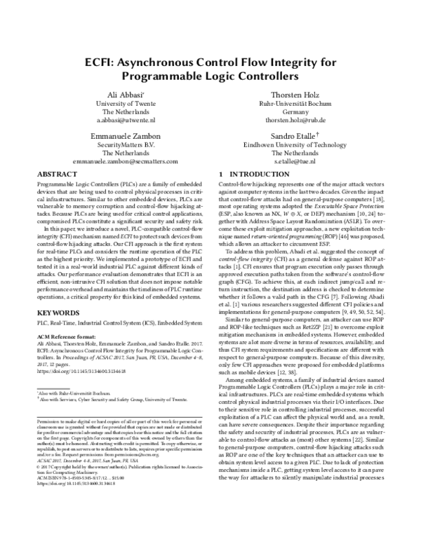
 Sandro Etalle