Academia.edu no longer supports Internet Explorer.
To browse Academia.edu and the wider internet faster and more securely, please take a few seconds to upgrade your browser.
2004, Proceedings - 2004 International Conference on Electrical, Electronic and Computer Engineering, ICEEC'04
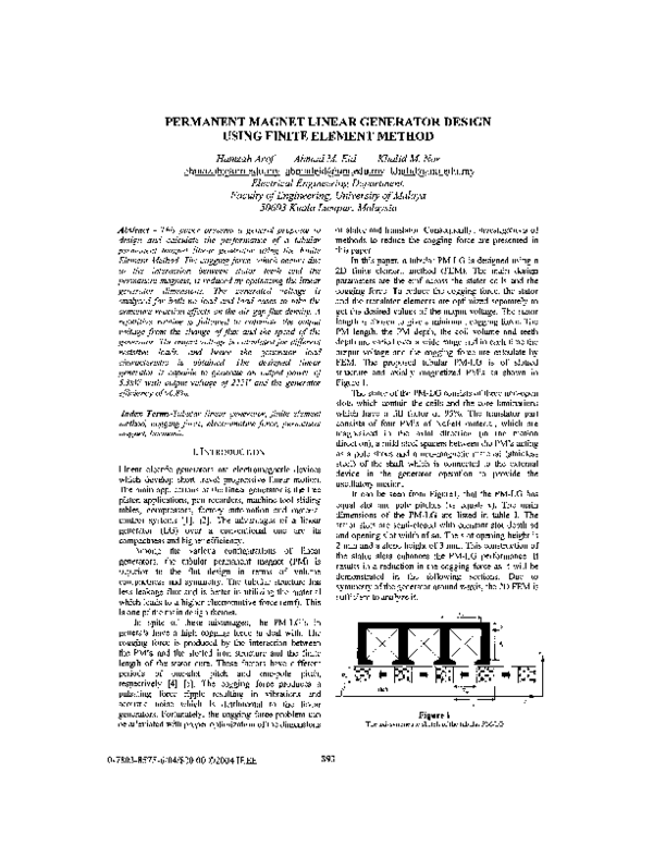
This paper presents a general proposal to design and calculate the performance of a tubular permanent magnet linear generator using the Finite Element Method, The cogging force, which occurs due to the interaction between stator teeth and the permanent magnets, is reduced by optimizing the linear generator dimensions. The generated voltage is analyzed for both no load and load cases to take the armature reaction effects on the air gap flux density. A repetitive routine is followed to calculate the output voltage from the change afflux and the speed of the generator. The output voltage is calculated for different resistive loads, and hence the generator load characteristic is obtained. The designed linear generator is capable to generate an output power of 5.3kW with output voltage of 222V and the generator efficiency of 96.8%. © 2004 IEEE. http://ieeexplore.ieee.org/xpl/articleDetails.jsp?arnumber=1374629
Journal of Power Electronics
Detent Force Reduction of Tubular Linear Generator Using an Axial Stepped Permanent Magnet Structure2006 •
39th International Universities Power Engineering Conference, UPEC 2004
Cogging force reduction using special magnet design for tubular permanent magnet linear generators2004 •
Various methods are explained to reduce the cogging force in tubular permanent magnet linear generator. The proposed methods depend on the variation of the permanent magnet construction. These methods include two approaches in the form of sloped magnets, and conical magnets in addition to the conventional method of varying the magnet length. Thus the magneto-motive force which is proportional to the permanent magnet length is not constant in the radial direction. The undesired cogging force ripples are calculated by a two dimensional Finite Element Method. Moreover, the generated electromotive force in the stator coils is calculated for each configuration of the permanent magnet. The experimental results agree well with those obtained from the FEM simulations. Reduction in the cogging force is obtained in the range of 40% while the root mean square of the output voltage is maintained. http://ieeexplore.ieee.org/xpls/abs_all.jsp?arnumber=1492075
– The paper presents design considerations of permanent magnet synchronous motors (PMSM) with concentrated windings and outer rotor topology for a light in-wheel electric vehicle (EV) application. A wide poles/slots range considered initially as a search space and machines with 48-poles/54-slots and 60-poles/63-slots were finally adopted. Finite element analysis (FEA) is employed in order to determine the performance of each motor. Systematic optimization on slots, permanent magnet's (PM) height and pole-arc to pole-pitch ratio was conducted, and relevant results are presented. It is shown that the maximum torque capability, the low torque ripple, the low cogging torque and low weight of the particular machines are well fitted to the specific EV application.
The multi-objective design of an axial-flux permanent magnet (PM) generator with the yokeless and segmented armature is done, for use in the small-scale direct-drive wind turbines. Using the multi-objective genetic algorithm technique, an optimisation process is performed for maximising the efficiency and minimising the cost, size, and mass of active materials, considering the practical constraints of the wind generator. The Pareto optimal fronts are used to find the best solutions. Also, a comparative study is performed to determine the most appropriate configuration among 12 configurations with the different combinations of poles and stator segments. Then, the selected optimal configuration is analysed using the three-dimensional (3D) finite element analysis (FEA). The inherent cogging torque of the PM wind generator affects the cut-in speed and start-up of the turbine. Thus, to improve the turbine performance, especially at low starting speeds, the generator cogging torque should be reduced to an acceptable level. In this study, using a new and practical approach, the peak-to-peak value of the cogging torque is reduced largely (81.4%), without notable reduction in the generator loadability. A prototype of the designed generator is fabricated and tested. The experimental results show good agreement with the 3D FEA simulation results.
IEEE Transactions on Magnetics
Design, Prototyping, and Analysis of a Novel Tubular Permanent-Magnet Linear Machine2000 •
Space-mapping optimization applied to the design of a novel electromagnetic actuator for active suspension
We present the design optimization of the magnetic pole and slot design options that minimize the cogging torque of permanent-magnet (PM) brushless generators for small wind turbine generators. Most small wind-turbines use direct-driven PM generators which have the characteristics of low speed and high efficiency. Small wind-turbines are usually self-starting and require very simple controls. The cogging torque is an inherent characteristic of PM generators, and is mainly caused by the generator's geometry. The inherent the cogging torque can cause problems during turbine start-up and cut-in in order to start softly and to run a power generator even when there is little wind power during turbine start-up. Thus, to improve the operation of small turbines, it is important to minimize the cogging torque. To determine the effects of the cogging torque reductions, we adjust the slot opening width, slot skewing, mounting method of magnets, magnet shape, and the opening and combinations of different numbers of slots per pole. Of these different methods, we combine the methods and optimized the design variables for the most significant design options affecting the cogging torque. Finally, we apply to the target design model and compare FEA simulation and measured results to validate the design optimization.
2009 •
… , 2007. IECON 2007 …
Analysis of a Segmented Brushless PM Machine Utilising Soft Magnetic Composites2008 •
IEEE Transactions on Industry Applications
Modeling and Experimental Verification of a Tubular Actuator for 20-g Acceleration in a Pick-and-Place Application2010 •
1st International Forum On Strategic Technology "e-Vehicle Technology", IFOST 2006
Design of a permanent magnet linear generator2006 •
Power Electronics Systems …
A novel outer-rotor permanent-magnet flux-switching machine for urban electric vehicle propulsion2009 •
IEEE Transactions on Industrial Electronics
IEEE TRANSACTION ON INDUSTRIAL ELECTRONICSIEEE Transactions on Magnetics
Analytical Modeling of the Open-Circuit Magnetic Field in Axial Flux Permanent-Magnet Machines With Semi-Closed Slots2000 •
IEEE Transactions on Industrial Electronics
Comparative Study of Air-Cored Axial Flux Permanent Magnet Machines with Different Stator Winding ConfigurationsIEEE Transactions on Industrial Electronics
Small Linear PM Oscillatory Motor: Magnetic Circuit Modeling Corrected by Axisymmetric 2-D FEM and Experimental Characterization2012 •
COMPEL: Int J for …
Design and analysis of a new outer-rotor permanent-magnet flux-switching machine for electric vehicle propulsion2011 •
39th International Universities Power Engineering Conference, UPEC 2004
Design of a 5 kW tubular permanent magnet linear generator2004 •
2009 International Conference on Electrical Machines and Systems
Characteristic investigations of a new three-phase flux-switching permanent magnet machine by FEM simulations and experimental verification2009 •
IEEE Transactions on Industrial Electronics
Influence of Leading Design Parameters on the Force Performance of a Complementary and Modular Linear Flux-Switching Permanent-Magnet Motor2000 •
IEEE Transactions on Industry Applications
A Practical Solution to Mitigate Vibrations in Industrial PM Motors Having Concentric WindingsIEEE Transactions on Magnetics
Design and Operation of Interior Permanent-Magnet Motors With Two Axial Segments and High Rotor Saliency2000 •
 Hamzah Arof