PRL 99, 206102 (2007)
PHYSICAL REVIEW LETTERS
week ending
16 NOVEMBER 2007
Effect of Surface Stress on the Stiffness of Cantilever Plates
Michael J. Lachut and John E. Sader*
Department of Mathematics and Statistics, The University of Melbourne, Victoria 3010, Australia
(Received 2 May 2007; published 15 November 2007)
Measurements over the past 30 years have indicated that surface stress can significantly affect the
stiffness of microcantilever plates. Several one-dimensional models based on beam theory have been
proposed to explain this phenomenon, but are found to be in violation of Newton’s third law, in spite of
their good agreement with measurements. In this Letter, we review this work and rigorously examine the
effect of surface stress on the stiffness of cantilever plates using a full three-dimensional model. This study
establishes the relationship between surface stress and cantilever stiffness, and in so doing elucidates its
scaling behavior with cantilever dimensions. The use of short nanoscale cantilevers thus presents the most
promising avenue for future investigations.
DOI: 10.1103/PhysRevLett.99.206102
PACS numbers: 68.37.Ps, 85.85.+j
Surface stress is an essential property of a solid surface
that has been widely studied using a range of experimental
techniques [1,2] and first principles calculations [3,4]. An
ability to control its effects lies at the core of many applications including the deposition of metal coatings [1],
epitaxial growth of semiconductor films [4], formation of
self-assembled monolayers [2], and design and construction of ultrasensitive mechanical sensors [5]. One such
sensing platform that has received considerable attention
is the microcantilever, due to its ease of construction,
implementation, and versatility [5]. In spite of this activity,
knowledge of the effect of surface stress on the stiffness of
cantilever plates remains an outstanding problem in the
physical sciences.
Over the past 30 years, measurements have suggested
that the stiffness of microcantilever plates can be tuned by
varying their surface stress. This phenomenon was first
reported by Lagowski et al. [6], who studied GaAs cantilevers as a function of surface preparation. These authors
proposed a one-dimensional model based on classical
beam theory for the effect that changes in strainindependent surface stress [6 –8] have on the resonant
frequency; see Eq. (5) of Ref. [6]. However, this model
was later shown to be incorrect by Gurtin et al. [8] who
wrote, ‘‘Within the framework of classical beam theory it
is shown that strain-independent surface stress has no
effect on the natural frequency of a thin cantilever beam.
Therefore, the experimental results of Lagowski, Gatos,
and Sproles must have a different explanation.’’ Since that
time, numerous other models based essentially on the
Lagowski hypothesis have been proposed [9–12]. Indeed,
such models have recently been used to argue that strainindependent surface stress dominates the dynamic response of microcantilevers in biomolecular recognition
measurements [11]. It is thus of critical importance to
assess the validity of such models.
Gurtin et al. [8] also examined the effects of surface
elasticity, i.e., ‘‘strain-dependent’’ surface stress, by considering a general constitutive model for surface stress [7],
and showed theoretically that this can affect cantilever
0031-9007=07=99(20)=206102(4)
stiffness. However, they concluded that this effect is negligible, leaving the experimental results of Ref. [6] unexplained. Other authors have subsequently adopted this idea
of surface elasticity [12 –14] in an attempt to account for
the experimental measurements.
In this Letter, we return to the original question: What is
the relationship between strain-independent surface stress
change and the stiffness of cantilever plates?
As we shall discuss, the origin of this relationship lies in
an alternative mechanical process to that proposed previously in Refs. [6,8–12].
To determine this relationship, we abandon the conventional approach that uses (approximate) classical beam
theory and replace it with a rigorous three-dimensional
treatment of the deformation problem, within the framework of the theory of linear elasticity. There are two
equivalent approaches to examining the effect of surface
stress change on cantilever stiffness: (i) monitor the change
in deflection for a given applied normal load, or (ii) monitor the resonant frequency change. Since the latter is most
commonly reported and easily measured, we focus our
investigation on the change in the fundamental resonant
frequency, while noting that our conclusions also apply to
the first approach.
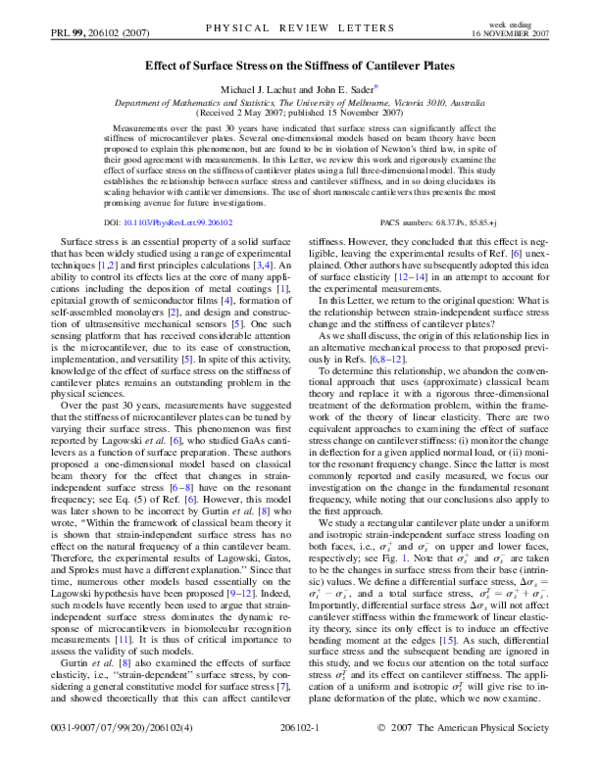
We study a rectangular cantilever plate under a uniform
and isotropic strain-independent surface stress loading on
�
both faces, i.e., ��
s and �s on upper and lower faces,
�
respectively; see Fig. 1. Note that ��
s and �s are taken
to be the changes in surface stress from their base (intrinsic) values. We define a differential surface stress, ��s �
�
T
�
�
��
s � �s , and a total surface stress, �s � �s � �s .
Importantly, differential surface stress ��s will not affect
cantilever stiffness within the framework of linear elasticity theory, since its only effect is to induce an effective
bending moment at the edges [15]. As such, differential
surface stress and the subsequent bending are ignored in
this study, and we focus our attention on the total surface
stress �Ts and its effect on cantilever stiffness. The application of a uniform and isotropic �Ts will give rise to inplane deformation of the plate, which we now examine.
206102-1
2007 The American Physical Society
�PHYSICAL REVIEW LETTERS
PRL 99, 206102 (2007)
z
y
x
L
σs+
b
σs−
decay in the x direction with a characteristic length scale
given by the cantilever width b. As such, there exists a
region near the clamp, x < O�b�, where nonzero in-plane
stresses exist, outside of which in-plane stress is zero.
Consequently, increasing the aspect ratio, L=b, of the
cantilever will reduce the overall effect of the applied
surface stress. To derive the scaling law, we use the (twodimensional) governing equation for small deflection of a
thin cantilever plate, D@ii @jj w � Nij @ij w � q, where w is
the deflection in the z direction, D is the flexural rigidity, N
is the in-plane stress tensor, and q is the applied load per
unit area. Making use of this plate equation and Eq. (1)
then leads to the following leading order scaling dependence for the effective flexural rigidity Deff ,
� �� � �
�
�1 � ���Ts b b 2
Deff
:
�1�O
L h
Eh
D
FIG. 1. Schematic of rectangular cantilever plate showing
coordinate system and applied surface stresses. Origin of coordinate system is at center of mass of the clamped end.
To begin, we consider the related problem of an unrestrained plate. Here, the no-traction boundary condition
along all edges ensures that the plate is in a state of uniform
plane stress, where the integral of the stress over the
thickness h is zero everywhere; i.e., the net in-plane stress
is zero. The displacement field for this problem is
�u; v� � ��1 � ���Ts �x; y�=�Eh�;
(2)
This result contrasts directly with the result obtained from
classical beam theory, which predicts a zero surface stress
effect. Since cantilever stiffness is proportional to the
flexural rigidity, the leading order dependence of the relative change in resonant frequency due to an applied surface
stress is
� �� �2
�!
b b
;
� ������
!0
L h
(1)
where u and v are displacements in the x and y directions,
respectively, E and � are the Young’s modulus and
Poisson’s ratio, respectively. Since the net in-plane stress
is zero, the resonant frequency of an unrestrained (free)
plate is independent of the applied surface stress.
In contrast, application of a uniform isotropic surface
stress �Ts to a cantilever plate will not yield uniform inplane deformation. To account for this behavior, the effect of the clamp must be included. This is achieved by
decomposing the original cantilever problem into two
subproblems.
Subproblem (1).—Deformation of an unrestrained plate
under application of a total surface stress �Ts .
Subproblem (2).—Cantilever plate with no surface stress
load and a specified in-plane displacement at its clamped
end: u � 0, v � �1 � ���Ts y=�Eh�, w � 0.
Superposition of these subproblems gives the required
in-plane deformation of the original cantilever problem,
with exact satisfaction of free edge and clamped boundary conditions. The in-plane stress distribution in Subproblem (2) is identical to the original cantilever problem,
since Subproblem (1) has zero net in-plane stress. As such,
resonant frequencies of the original cantilever problem are
given by those of Subproblem (2).
An exact analytical solution to Subproblem (2) poses a
formidable challenge. To gain insight into the dependence
of surface stress on cantilever stiffness, we initially examine its scaling behavior. The load at the clamped end in
Subproblem (2) will induce nonzero in-plane stresses that
week ending
16 NOVEMBER 2007
(3)
where !0 is the resonant frequency in the absence of an
applied surface stress, �! � ! � !0 , �� � �1 � ���Ts =�Eh�
is the dimensionless surface stress change, and ���� is a
function purely dependent on Poisson’s ratio �. This expression is expected to be valid in the limit L � b � h,
and when surface stress has a small effect on stiffness,
which is frequently encountered in practice.
Next we solve Subproblem (2) using a full threedimensional finite element analysis [16]. To begin, we
examine the prediction of Eq. (3) that the change in resonant frequency varies in proportion to the square of width
to thickness ratio b=h, for a fixed aspect ratio L=b. Figure 2
presents results for the relative change in resonant frequency, �!=!0 , which have been scaled by �b=h�2 , in
accordance with Eq. (3). From Fig. 2, it is strikingly
evident that Eq. (3) accurately captures the dominant width
ratio b=h dependence, with all curves collapsing onto each
other for a given Poisson’s ratio �. Also note that the
frequency shift depends strongly on Poisson’s ratio, with
increasing � enhancing the effect. This is to be expected,
since the applied load is a deformation in the y direction,
and the stiffness probed is predominantly in the x direction.
Interestingly, we find that for � � 0, varying the surface
stress has a negligible effect on stiffness in comparison to
nonzero �.
The numerical results in Fig. 2 include all nonlinear
surface stress effects, which have been ignored in the
formulation of Eq. (3). Consequently, to make a quantitative and rigorous comparison to Eq. (3), we henceforth
206102-2
�PHYSICAL REVIEW LETTERS
PRL 99, 206102 (2007)
result into Eq. (3) gives the required dependence of the
relative frequency shift on surface stress change,
0.004
L /b = 25 / 3
� �� �
��1 � ���Ts b b 2
�!
� �0:042
:
L h
Eh
!0
0.002
∆ω
ω0
0
−0.002
Increasing Poisson's Ratio
ν
−0.004
−2
−1
0
(b / h )
1
2
2
σ
2
FIG. 2. Results for relative frequency shift �!=!0 vs ��b=h�
�
for L=b � 25=3. Three groups of Poisson’s ratio shown: � � 0,
0.25, 0.49. Each group contains b=h � 16, 19.2, 24, 32, 48.
extract the linear portion of these numerical results using
linear regression and report these results only.
In Fig. 3, we assess the aspect ratio (L=b) dependence
predicted in Eq. (3). Results are presented for a range of
aspect ratios L=b, Poisson’s ratio � � 0:25, with width
ratios b=h corresponding to those used in Fig. 2. Results
for other nonzero Poisson’s ratios are similar to those in
Fig. 3, apart from a change in magnitude. The vertical axis
is scaled in accordance with Eq. (3) to examine its validity.
From Fig. 3, it is clear that Eq. (3) also captures the
dominant aspect ratio dependence for large L=b, which is
the regime in which it was derived, while a higher order
dependence on aspect ratio is also visible for smaller L=b;
this higher order dependence can be calculated from results
in Fig. 3 if required. These results confirm the validity of
the scaling argument behind Eq. (3).
To determine ����, the data in Fig. 3 are extrapolated in
the binary limit L=b ! 1 and b=h ! 1. Given the linearity of the data in this limit, extrapolation is robust and
accurate. Results of extrapolation for various Poisson’s
ratio are then used to evaluate ����. We find that ����
varies approximately linearly with Poisson’s ratio and is
well described by ���� � �0:042� [17]. Substituting this
Normalized Frequency Shift Ω
0.012
ν = 0.25
0.01
Increasing b / h
0.008
0.006
0.004
0
week ending
16 NOVEMBER 2007
0.1
0.2
0.3
0.4
0.5
b/L
FIG. 3. Results for normalized frequency shift �
2
�
j; b=h � 16, 19.2, 24, 32, 48; � �
j�!lin =!0 j=j��b=L��b=h�
0:25. Subscript ‘‘lin’’ indicates result from linear regression.
(4)
We emphasize that this result is not inconsistent with the
null result of Gurtin et al. [8], since they implicitly considered the formal limit L=b ! 1 using classical beam
theory. In this limit, Eq. (4) also predicts that surface stress
change has no effect. The mechanism giving rise to surface
stress induced stiffness changes lies in development of inplane stresses near the clamp, which are inherently ignored
in beam theory.
The resonant frequency change is dictated by the ratio of
the modified total surface stress ��1 � ���Ts to the stiffness
kref � Eh3 L=b3 . Increasing the length L therefore has a
relatively weak effect in comparison to changing the thickness or width. Importantly, this scaling dependence differs
considerably from that for surface elasticity effects (straindependent surface stress) [13] and can be used as a signature to investigate the presence of strain-independent
surface stress effects. Indeed, probing the scaling dependence of strain-independent and strain-dependent surface
stress contributions with cantilever geometry allows for
determination of the underlying mechanism driving stress
induced changes in cantilever stiffness. In principle, Eq. (4)
could be combined with static bending measurements,
which probe differential surface stress, to determine surface stress changes on each face of the cantilever, i.e.,
�
individual measurement of ��
s and �s . Such application
would, of course, be contingent on the frequency resolution
achievable in practice. Equation (4) establishes that use of
low aspect ratio cantilevers and reduction in thickness will
yield the greatest sensitivity. We emphasize that our study
is applicable to nanoscale structures where the classical
theory of elasticity is valid, the subject of which was
investigated recently [18]. Miniaturization to the nanoscale
thus presents a promising avenue for future developments.
We now examine the validity of recent models [9–12]
derived using beam theory. Similar to Lagowski’s model,
these models attempt to simplify the problem by replacing
surface stress with an external axial force equal to the total
surface stress �Ts integrated over the cantilever dimensions.
However, such approaches are not physically justified
since the cantilever free end is unrestrained with zero net
force. Application of a (uniform) axial force along the
beam is therefore in direct violation of Newton’s third
law. As explained by Gurtin et al. [8], application of
surface stress will result in a commensurate stress of
opposite sign within the beam material, ensuring zero net
in-plane stress across the beam [13]. Therefore, the physical basis of all such one-dimensional models based on
beam theory is flawed. The true effect of surface stress
change can only be captured using higher dimensional
models that account for nonuniform distribution of inplane stresses in the cantilever, as given above.
206102-3
�PRL 99, 206102 (2007)
PHYSICAL REVIEW LETTERS
Next, we compare predictions of Eq. (4) with published
experimental results for surface stress induced changes in
cantilever stiffness. While the primary focus of Ref. [6]
was (intrinsic) residual stress, modification of surface
properties by etching was also examined; see Fig. 4 of
Ref. [6]. Variations in resonant frequency from a few
percent to nearly 100% are reported. Using their unphysical model (see above), surface stress changes in the vicinity of 0:2 N=m are calculated, which are in agreement with
expected values. While a direct comparison with their
measurements is not possible, due to omission of specific
cantilever dimensions with resonant frequency shifts in
their study, we can provide an estimate of the relative
frequency shift. Using typical values for the material properties of GaAs and the limiting cantilever geometry L=b �
6, b=h � 500 [6], yields a relative frequency shift
�!=!0 � 10�4 , which is significantly smaller than the
shift observed in Ref. [6]. The observations in Ref. [6]
are therefore not due to strain-independent surface stress;
Gurtin et al. [8] obtained the same conclusion based on the
null result from beam theory.
Recent measurements use silicon and silicon nitride
microcantilevers and monitor resonant frequency change
as the surface is modified. Since absolute surface stress
change is not measured, direct comparison with Eq. (4) is
again not possible. Instead, we determine the required
surface stress change to recover the experimentally observed frequency shifts. While significant variation exists
between measurements in different studies, the range of
frequency shifts is �!=!0 � 0:002–0:06. Reference [10]
used gold coated silicon rectangular cantilevers with dimensions 499 97 0:8 �m3 and reported frequency
shifts up to �!=!0 � 0:01 following an amino-ethanethiol-gold adsorption binding event. These authors also
measured surface stress change from the static deflection
of the cantilever and compared it to dynamic measurements based on an (unphysical) axial stress model; see
above. Good agreement was found between these independent measurements and the axial stress model for the first
six modes. However, from Eq. (4), we find that the total
surface stress change required to achieve this maximum
frequency shift is �Ts � 60 N=m. This value is orders of
magnitude higher than typical surface stress changes, and
�105 times larger than surface stresses reported in
Ref. [10]. A similar conclusion is drawn on measurements
in Refs. [9,19]. This analysis indicates that these experimental results are not due to the effects of strainindependent surface stress, as has been implicitly assumed.
We have investigated the effects of strain-independent
surface stress change on the stiffness of cantilever plates
using a three-dimensional analysis and scaling argument.
This overcomes the limitations of beam theory, which
predicts a null effect of strain-independent surface stress.
We also discussed the invalidity of so-called axial stress
models that proliferate the current literature. Our analysis
indicates that current measurements of surface induced
stiffness changes are not due to strain-independent sur-
week ending
16 NOVEMBER 2007
face stress. While changes in surface elasticity have been
proposed to explain these experiments, a quantitative
comparison with measurements remains elusive. The scaling laws of these complementary approaches can thus be
used to investigate the true nature of surface induced
changes in cantilever stiffness and presents a rigorous
avenue for elucidating the underlying mechanism. The
use of low aspect ratio nanoscale cantilevers presents the
most promising approach for investigating the effects of
strain-independent surface stress change on cantilever
stiffness.
The authors gratefully acknowledge support of the
Particulate Fluids Processing Centre and the Australian
Research Council Grants Scheme.
*jsader@unimelb.edu.au
[1] G. G. Stoney, Proc. R. Soc. A 82, 172 (1909); G. Hass and
R. E. Thun, Physics of Thin Films (Academic, New York,
1966).
[2] R. Berger et al., Science 276, 2021 (1997).
[3] V. Fiorentini, M. Methfessel, and M. Scheffler, Phys. Rev.
Lett. 71, 1051 (1993).
[4] H. Ibach, Surf. Sci. Rep. 29, 195 (1997).
[5] N. V. Lavrik, M. J. Sepaniak, and P. G. Datskos, Rev. Sci.
Instrum. 75, 2229 (2004).
[6] J. Lagowski, H. C. Gatos, and E. S. Sproles, Jr., Appl.
Phys. Lett. 26, 493 (1975).
[7] M. E. Gurtin and A. I. Murdoch, Arch. Ration. Mech.
Anal. 57, 291 (1975). Constitutive model for surface stress
with strain-independent and strain-dependent components.
[8] M. E. Gurtin, X. Markenscoff, and R. N. Thurston, Appl.
Phys. Lett. 29, 529 (1976).
[9] G. Y. Chen et al., J. Appl. Phys. 77, 3618 (1995);
Y. Zhang, Q. Ren, and Y.-P. Zhao, J. Phys. D 37, 2140
(2004); K. S. Hwang et al., Appl. Phys. Lett. 89, 173905
(2006).
[10] A. W. McFarland et al., Appl. Phys. Lett. 87, 053505
(2005).
[11] J. Dorignac et al., Phys. Rev. Lett. 96, 186105 (2006).
[12] G. F. Wang and X. Q. Feng, Appl. Phys. Lett. 90, 231904
(2007).
[13] P. Lu et al., Phys. Rev. B 72, 085405 (2005).
[14] D. W. Dareing and T. Thundat, J. Appl. Phys. 97, 043526
(2005).
[15] J. E. Sader, J. Appl. Phys. 89, 2911 (2001).
[16] LUSAS is a trademark of and is available from FEA Ltd.
Forge House, 66 High Street, Kingston Upon Thames,
Surrey KT1 1HN, UK. The 3D quadrilateral elements with
linear interpolation were used. Mesh was refined to 99%
convergence.
[17] Corresponding analysis of a cantilever with a static uniformly distributed normal load at its free end gave identical conclusions, but with ���� � �0:063�.
[18] R. Maranganti and P. Sharma, Phys. Rev. Lett. 98, 195504
(2007).
[19] S. Cherian and T. Thundat, Appl. Phys. Lett. 80, 2219
(2002); J. H. Lee, T. S. Kim, and K. H. Yoon, Appl. Phys.
Lett. 84, 3187 (2004).
206102-4
�
 Michael Lachut