SLAC-PUB-14448
A PROOF-OF-PRINCIPLE ECHO-ENABLED HARMONIC GENERATION
EXPERIMENT AT SLAC∗
M. Dunning† , E. Colby, Y. Ding, J. Frederico, S. Gilevich, C. Hast, K. Jobe, D. McCormick,
J. Nelson, T.O. Raubenheimer, K. Soong, G. Stupakov, Z. Szalata, D. Walz, S. Weathersby,
M. Woodley, D. Xiang, SLAC, Menlo Park, CA, USA
J. Corlett, J. Qiang, G. Penn, S. Prestemon, R. Schlueter, M. Venturini, W. Wan
LBNL, Berkeley, CA, USA
P-L. Pernet, EPFL, Lausanne, Switzerland
Abstract
In this paper we describe the technical design of an ongoing proof-of-principle echo-enabled harmonic generation (EEHG) experiment at the Next Linear Collider Test
Accelerator (NLCTA) at SLAC. We present the design considerations and the technical details of the experiment.
a chicane (termed chiane minus one, or C-1), the beam is
typically used for high-gradient rf structure testing, or can
be used for various experiments including the SLAC E163
laser acceleration experiments [6].
INTRODUCTION
Recently a new method, entitled echo-enabled harmonic
generation, was proposed for generation of high harmonics using the beam echo effect [1, 2]. In an EEHG free
electron laser (FEL), an electron beam is energy modulated
in a modulator and then sent through a dispersive section
with a high dispersion strength. After this first stage, the
modulation obtained in the modulator is macroscopically
washed out, while simultaneously introducing complicated
fine structure (separated energy bands) into the phase space
of the beam. A second laser is used to further modulate the
beam energy in a second modulator. After passing through
a second dispersive section, the separated energy bands will
be converted into current modulation and the echo signal
then occurs as a recoherence effect caused by the mixing
of the correlations between the modulation in the second
modulator and the fine structures in the beam.
The EEHG scheme has a remarkable up-frequency conversion efficiency; it has been shown that the EEHG FEL
scheme may allow generation of soft x-rays directly from
a UV seed laser in a single stage [3]. In order to confirm
the physics behind the EEHG technique and benchmark the
theory, a proof-of-principle EEHG experiment was planned
at SLAC. The experiment is now in a commissioning stage
and the preliminary results are reported in a separate paper
of these proceedings [4]. In this paper we present the design considerations and the details of the experiment setup.
LAYOUT
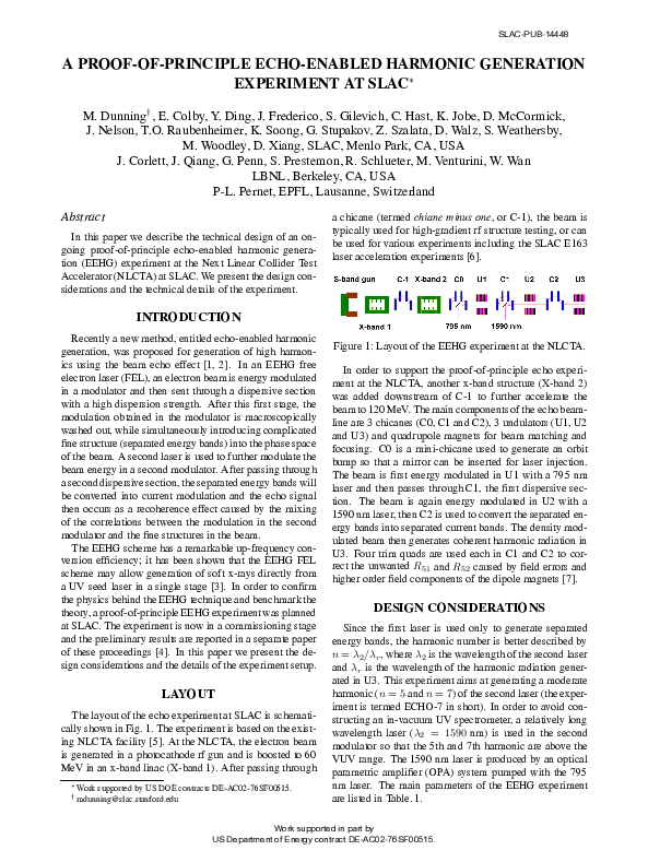
The layout of the echo experiment at SLAC is schematically shown in Fig. 1. The experiment is based on the existing NLCTA facility [5]. At the NLCTA, the electron beam
is generated in a photocathode rf gun and is boosted to 60
MeV in an x-band linac (X-band 1). After passing through
∗ Work
supported by US DOE contracts DE-AC02-76SF00515.
† mdunning@slac.stanford.edu
Figure 1: Layout of the EEHG experiment at the NLCTA.
In order to support the proof-of-principle echo experiment at the NLCTA, another x-band structure (X-band 2)
was added downstream of C-1 to further accelerate the
beam to 120 MeV. The main components of the echo beamline are 3 chicanes (C0, C1 and C2), 3 undulators (U1, U2
and U3) and quadrupole magnets for beam matching and
focusing. C0 is a mini-chicane used to generate an orbit
bump so that a mirror can be inserted for laser injection.
The beam is first energy modulated in U1 with a 795 nm
laser and then passes through C1, the first dispersive section. The beam is again energy modulated in U2 with a
1590 nm laser, then C2 is used to convert the separated energy bands into separated current bands. The density modulated beam then generates coherent harmonic radiation in
U3. Four trim quads are used each in C1 and C2 to correct the unwanted R51 and R52 caused by field errors and
higher order field components of the dipole magnets [7].
DESIGN CONSIDERATIONS
Since the first laser is used only to generate separated
energy bands, the harmonic number is better described by
n = λ2 /λr , where λ2 is the wavelength of the second laser
and λr is the wavelength of the harmonic radiation generated in U3. This experiment aims at generating a moderate
harmonic (n = 5 and n = 7) of the second laser (the experiment is termed ECHO-7 in short). In order to avoid constructing an in-vacuum UV spectrometer, a relatively long
wavelength laser (λ2 = 1590 nm) is used in the second
modulator so that the 5th and 7th harmonic are above the
VUV range. The 1590 nm laser is produced by an optical
parametric amplifier (OPA) system pumped with the 795
nm laser. The main parameters of the EEHG experiment
are listed in Table. 1.
Work supported in part by
US Department of Energy contract DE-AC02-76SF00515.
�SLAC-PUB-14448
Table 1: Main parameters of the EEHG experiment.
Beam energy
Normalized emittance
Bunch charge
Laser wavelength in U1
Laser wavelength in U2
Slice energy spread
Np × λu for U1
Np × λu for U2
Np × λu for U3
Peak energy modulation in U1 and U2
R56 for C1 and C2
Radiation wavelength in radiator
120 MeV
8 mm-mrad
25 pC
795 nm
1590 nm
2-10 keV
10 × 3.3 cm
10 × 5.5 cm
10 × 2 cm
10-40 keV
1.0-9.0 mm
318 and 227 nm
U1 and U2 have fixed gaps while U3 is designed to be
adjustable in gap so that it can be tuned to the 5th or 7th
harmonic of the second laser.
Because EEHG requires a long term memory of the
beam phase space, it is in general sensitive to diffusion
effects. For a low energy beam, typically the quantum
diffusion from incoherent synchrotron radiation and incoherent undulator radiation is not a serious issue and the
second order effect from the emittance (particles with different betatron amplitude have different path lengths) is a
major concern. The lattice is carefully designed to have
a small βmax /βmin to mitigate the smearing from second
order transport effects. For the 7th harmonic case, the longitudinal phase space at the entrance to U3 is simulated
with elegant [8] and is shown in Fig. 2 for two different values of the transverse emittance. In order to quantify the smearing effect, a bunch with vanishing length was
tracked through the echo beam line; at the beamline exit
the bunch length is increased to approximately 80 nm. The
simulations indicate that the current beam quality (about 8
mm-mrad emittance) is adequate for generating the 7th harmonic, but improved beam quality is needed if one plans to
generate higher harmonics. Future plans are to replace the
photocathode and drive laser and modify C-1, to achieve
an emittance of approximately 2 mm-mrad. This will enable generation and measurement of the 15th harmonic of
the second laser in U3 (3rd harmonic of the fundamental
radiation which is tuned to the 5th harmonic of the second
laser).
Figure 2: Phase space at the entrance to U3 for different
beam emittances: 1 mm mrad (left); 8 mm mrad (right).
In addition to second order effects from the transverse
emittance, several other effects could wash out the fine
structure in the beam, including misalignment of the quads,
field errors of the dipoles, and the non-zero field integral of
the undulators. Extensive simulations have been performed
to set the corresponding tolerances. For instance, the beam
was tracked in simulation through a chicane of which the
dipoles had 0.5% field errors. The simulated phase space
after C2 is shown in Fig 3, where it is shown that the
fine structure is nearly completely washed out without trim
quad correction. Analysis shows that the smearing effect is
from the unwanted x − z coupling from the non-zero R51
and R52 caused by the field errors. For this specific case,
we have R51 ≈ 2.4 × 10⁻⁴ , R52 ≈ 2.9 × 10⁻⁴ and the
bunching factor is about 0.2%. Considering the fact that at
the entrance to the chicane σx ≈ 0.3 mm and σx′ ≈ 0.13
mrad, the x − z�coupling may wash out any structure that
is finer than 2π (σx R51 )2 + (σx′ R52 )2 ≈ 500 nm.
Figure 3: Longitudinal phase space at the exit of C2 with
(right) and without (left) trim quad correction when 0.5%
field error is present.
In our design the dipoles are powered by the same power
supply, but due to mechanical differences, the field integral
has some error. In order to reduce the field errors to within
0.1%, the trim coils are integrated with the main windings
of the dipoles so that one can finely adjust the trim coil current to compensate for the field differences from the main
windings. Furthermore, two trim quads are also used in the
chicane to correct the field error and the higher order field
components. Simulation shows that by empirically adjusting the strength of the trim quads, one can greatly reduce
the R51 and R52 so that the x − z coupling effect is significantly mitigated. For the example above, when the trim
quads were adjusted to proper settings, R51 and R52 were
reduced by one order of magnitude and the fine structure
was restored after C2 (see right plot of Fig. 3).
The beam will receive a kick after exiting the undulator
if the first field integral is non-zero. Similarly the beam
will have an offset after exiting the undulator if the second
field integral is non-zero. The effect of the kick is similar
to a dipole that causes x − z coupling which tends to wash
out the fine structure in phase space. In order not to significantly affect the EEHG performances, the specifications for
the first field integral of the undulators is set to 10 G·cm,
which corresponds to a kick of about 25 µrad. The second
field integral is set to 1000 G·cm2 which corresponds to an
offset of about 25 µm.
Work supported in part by
US Department of Energy contract DE-AC02-76SF00515.
�SLAC-PUB-14448
Diagnostics for measuring the echo signal are also a major concern. While backward transition radiation in the UV
range can still be generated with an optical transition radiation (OTR) foil, it is not suitable for coherent radiation
generation when the electron beam transverse size is comparable to or larger than γλr . The transverse beam size
does not affect the phase of the radiation if it is observed
on-axis in far field. However, the OTR intensity peaks at
1/γ. So if the radiation is measured at this angle, the transverse size of the beam will affect the phase of the radiation,
and thus the radiation intensity is significantly suppressed
when beam size is larger than γλr . For our case the beam
size is about one order of magnitude larger than γλr when
λr = 227 nm, and analysis shows that we will measure
few coherent photons with an OTR foil. As an alternative,
undulator radiation intensity peaks in the forward direction
and is much less sensitive to the transverse beam size. A
third undulator was installed for generating coherent radiation at 318 nm and 227 nm.
EXPERIMENT SETUP
The beam line was completed in April 2010 and
presently the experiment is in the commissioning stage.
Some preliminary results are presented in these proceedings [4]. Here we describe some details of the experiment
setup.
An image of the second chicane, C2, after installation is
shown in Fig. 4, where the blue elements are the dipoles
and orange elements are the trim quads for field error correction. The trim quads can be moved remotely so that no
beam kick results when the bend angle is changed. Two
mirrors were installed in the center of the chicane: one is
used to reflect out the upstream laser so that the laser power
and mode quality can be monitored during the experiment,
and the other is used to inject the downstream laser. By
reflecting out the laser, the background in the echo signal
measurement is also effectively reduced.
and is analyzed with an oscilloscope (2.5 GHz bandwidth).
By referencing the signals to an external trigger, the laser
and beam can be synchronized to within approximately
30 ps. More precise timing is done by using a fast scanning
delay stage and measuring the coherent radiation enhancement that is produced when the beam is bunched by each
modulator and dispersive section.
Figure 5: Image of U2 after installation.
SUMMARY
In order to confirm the physics behind the EEHG
technique and benchmark the theory, a proof-of-principle
EEHG experiment is underway at the NLCTA at SLAC. It
has gone from the design stage into commissioning within
one year. After the 5th and 7th harmonics (227 nm and
318 nm) are measured, beamline upgrades are planned to
enable the measurement of the 15th harmonic (106 nm).
ACKNOWLEDGEMENTS
We thank C. Adolphsen, J. Byrd, A. Chao, P. Emma, W.
Fawley, J. Frisch , G. Hays, Z. Huang, H. Loos, H. Nuhn, F.
Wang, X. Wang W. White, J. Wu and A. Zholents for helpful discussions, comments and commissioning assistances.
REFERENCES
Figure 4: Image of C2 after installation.
The second undulator, U2, is shown in Fig. 5. OTR
screens are installed immediately upstream and downstream of each undulator, which are used for laser-electron
spatial overlap. Another OTR screen immediately downstream of each undulator is used to reflect out the laser and
undulator radiation for temporal synchronization; the radiation is detected by a fast photodiode (2 GHz bandwidth)
[1] G. Stupakov, Phys. Rev. Lett, 102 (2009) 074801.
[2] D. Xiang and G. Stupakov, Phys. Rev. ST-AB, 12 (2009)
030702.
[3] D. Xiang and G. Stupakov, “Coherent soft x-ray generation
in the water window with the EEHG scheme”, Proceedings
of PAC’09.
[4] D. Xiang et al., “Preliminary results of the echo-seeding experiment ECHO-7 at SLAC”, These proceedings, (2010).
[5] “NLC test accelerator conceptual design report”, SLACReport-411, (1993).
[6] C. Sears et al., Phys. Rev. ST-AB, 11 (2008) 101301.
[7] D. Xiang and G. Stupakov, “Tolerance study for the echoenabled harmonic generation free electron laser”, Proceedings of PAC’09, (2009); see also SLAC-PUB-13644.
[8] M. Borland, ”Elegant: A flexible SDDS-compliant code for
accelerator simulation,” Advanced Photon Source LS-287,
September, (2000).
Work supported in part by
US Department of Energy contract DE-AC02-76SF00515.
�
 S. Gilevich