US5772050A - Ink stamp rack - Google Patents
Ink stamp rack Download PDFInfo
- Publication number
- US5772050A US5772050A US08/808,464 US80846497A US5772050A US 5772050 A US5772050 A US 5772050A US 80846497 A US80846497 A US 80846497A US 5772050 A US5772050 A US 5772050A
- Authority
- US
- United States
- Prior art keywords
- post
- disk
- flange
- hole
- stamp rack
- Prior art date
- Legal status (The legal status is an assumption and is not a legal conclusion. Google has not performed a legal analysis and makes no representation as to the accuracy of the status listed.)
- Expired - Lifetime
Links
- 238000005299 abrasion Methods 0.000 description 1
- 230000004048 modification Effects 0.000 description 1
- 238000012986 modification Methods 0.000 description 1
Images


Classifications
-
- B—PERFORMING OPERATIONS; TRANSPORTING
- B41—PRINTING; LINING MACHINES; TYPEWRITERS; STAMPS
- B41K—STAMPS; STAMPING OR NUMBERING APPARATUS OR DEVICES
- B41K1/00—Portable hand-operated devices without means for supporting or locating the articles to be stamped, i.e. hand stamps; Inking devices or other accessories therefor
- B41K1/36—Details
- B41K1/58—Stands or other means for keeping hand stamps or the like within easy reach
Definitions
- the present utility model relates to a rack and, more particularly, to an ink stamp rack having at least one disk supported by a post which is fixedly connected to a base and a cap connected to the post to position the disk which has a plurality of recesses defined therein such that the ink stamps can be received in the recesses.
- Stamps are used in a variety of fields in offices and which are convenient to mark documents with writing or symbols in colored ink.
- a clerical worker has many stamps which are stored in a drawer or a box or the like so that they may be selected conveniently.
- storing stamps in a drawer or a box results in abrasion to the stamps and this reduces their lifespan.
- the drawer and/or the box for the ink stamps received therein will be contaminated by ink on the stamps.
- the present utility model intends to provide an ink stamp rack which has at least one disk disposed thereto which has a plurality of recesses defined therein so as to mitigate and/or obviate the above-mentioned problems.
- the present utility model provides an ink stamp rack which comprises a base having a first central hole defined therein and a skirt portion extending downwardly from a periphery thereof.
- a first post has a first end having a first flange extending radially therefrom and a first hole defined in the first post beneath the first flange, and a second end which has an annular flange extending radially therefrom and an engaging rod extending longitudinally therefrom.
- the second end of the first post is connected to the base by engaging the engaging rod with the first central hole of the base.
- a first disk has a second central hole defined therein so as to be mounted to the first end of the first post and supported by the first flange.
- a plurality of first recesses are defined in the first disk along a periphery of the first disk.
- a second post has a first end having a second flange extending radially therefrom and a second end which has a first protrusion extending radially from a periphery thereof so as to extend through the first holes of the first post.
- a second disk has a third central hole defined therein so as to be mounted to the first end of the second post and supported by the second flange.
- a cap is mounted to the first end of the second post to position the second disk.
- FIG. 1 is a perspective view of an ink stamp rack in accordance with the present utility model
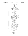
- FIG. 2 is an exploded view of the ink stamp rack in accordance with the present utility model
- FIG. 3 is a side elevational view, partly in section, of the ink stamp rack in accordance with the present utility model
- FIG. 4 is a side elevational view, partly in section, of the ink stamp rack in accordance with the present utility model seen from another direction, and
- FIG. 5 is a side elevational view, partly in section, of another embodiment of the ink stamp rack in accordance with the present utility model.
- an ink stamp rack in accordance with the present utility model generally includes a base 11 having a first central hole 111 defined therethrough and a skirt portion 101 extending downwardly from a periphery thereof.
- the skirt portion 101 has at least one protrusion 113 extending inwardly and radially therefrom.
- a first post 21 has a first end and a second end which has an annular flange 212 extending radially therefrom and an engaging rod 211 extends longitudinally therefrom.
- the engaging rod 211 has a threaded portion defined in an outer periphery thereof.
- a first flange 216 extends radially from the first post 21 near the first end of the first post 21 and a first hole 218 is defined in the first post 21 beneath the first flange 216.
- Two longitudinal grooves 210 are defined longitudinally opposite in an inner periphery of the first post 21.
- An inner plate 12 is disposed to a bottom of the base 10 and has a central threaded hole 121 defined therethrough such that the threaded portion of the engaging rod 211 is engaged with the threaded hole 121 of the inner plate 12.
- the inner plate 12 has a notch 122 defined in an outer periphery thereof such that when the inner plate 12 is disposed to the bottom of the base 10, the protrusion 113 is received in the notch 122.
- a first disk 32 has a second central hole 321 defined therein so as to be mounted to the first end of the first post 21 and supported by the first flange 216.
- a plurality of first recesses 322 are defined in the first disk 32 along a periphery thereof and each of the first recesses 322 is a substantially Y-shaped recess.
- a second post 22 has a first end and a second end and has two splines 221 extending diametrically opposite therefrom.
- the second end of the second post 22 has a first protrusion 223 extending radially therefrom so as to extend through the first hole 218 of the first post 21 with the two splines 221 received in the two longitudinal grooves 210 of the first post 21.
- Two slits 225 are defined longitudinally therein and the first protrusion 223 is located between the two slits 225 so that the first protrusion 223 can be slightly pushed inwardly before it is inserted into the first hole 218.
- a second flange 224 extends radially therefrom near the first end of the second post 22.
- the second post 22 has a second hole 226 defined therein beneath the second flange 224.
- a second disk 31 has a third central hole 311 defined therein so as to be mounted to the first end of the second post 22 and supported by the second flange 224.
- a plurality of second recesses 312 are defined in the second disk 31 along a periphery of the second disk 31 and each of the second recesses 312 is a substantially Y-shaped recess.
- a cap 40 is mounted to the first end of the second post 22 to position the second disk 31 on the second post 22 wherein the cap 40 has a second protrusion 43 extending radially therefrom such that when the cap 40 is mounted to the first end of the second post 22, the second protrusion 43 extends through the second hole 226.
- two slits 42 are defined longitudinally therein and the second protrusion 43 is located between the two slits 42 so that the second protrusion 43 can be slightly pushed inwardly before it is inserted into the second hole 226. Accordingly, stamps (not shown) can hung on the first and second disks 32, 31 and are received in the first and second recesses 322, 312.
- the ink stamp rack is also to be used by directly engaging the cap 40 to the first end of the first post 21 with the second protrusion 43 extending through the first hole 218 of the first post 21.
Landscapes
- Holo Graphy (AREA)
- Gyroscopes (AREA)
- Immobilizing And Processing Of Enzymes And Microorganisms (AREA)
- Pens And Brushes (AREA)
Abstract
A stamp rack includes a base, an inner plate disposed to a bottom of the base, a first post disposed to the base wherein an annular flange and an engaging rod respectively extend radially and longitudinally from a second end of the first post, a first disk mounted to the first post and supported by first flange, a second post securely inserted into the first post by extending a protrusion of the second post through a hole defined in the first end of the first post, a second flange extending radially from the second post so as to support a second disk mounted to the second post and a cap mounted to the second post to position the second disk. Each of the first disk and the second disk has a plurality of Y-shaped recesses defined therein for receiving stamps therein.
Description
1. Field of the Invention
The present utility model relates to a rack and, more particularly, to an ink stamp rack having at least one disk supported by a post which is fixedly connected to a base and a cap connected to the post to position the disk which has a plurality of recesses defined therein such that the ink stamps can be received in the recesses.
2. Brief Description of the Prior Art
Stamps are used in a variety of fields in offices and which are convenient to mark documents with writing or symbols in colored ink. Generally, a clerical worker has many stamps which are stored in a drawer or a box or the like so that they may be selected conveniently. However, storing stamps in a drawer or a box results in abrasion to the stamps and this reduces their lifespan. Furthermore, the drawer and/or the box for the ink stamps received therein will be contaminated by ink on the stamps.
The present utility model intends to provide an ink stamp rack which has at least one disk disposed thereto which has a plurality of recesses defined therein so as to mitigate and/or obviate the above-mentioned problems.
The present utility model provides an ink stamp rack which comprises a base having a first central hole defined therein and a skirt portion extending downwardly from a periphery thereof.
A first post has a first end having a first flange extending radially therefrom and a first hole defined in the first post beneath the first flange, and a second end which has an annular flange extending radially therefrom and an engaging rod extending longitudinally therefrom. The second end of the first post is connected to the base by engaging the engaging rod with the first central hole of the base.
A first disk has a second central hole defined therein so as to be mounted to the first end of the first post and supported by the first flange. A plurality of first recesses are defined in the first disk along a periphery of the first disk.
A second post has a first end having a second flange extending radially therefrom and a second end which has a first protrusion extending radially from a periphery thereof so as to extend through the first holes of the first post.
A second disk has a third central hole defined therein so as to be mounted to the first end of the second post and supported by the second flange. A cap is mounted to the first end of the second post to position the second disk.
It is an object of the present utility model to provide an ink stamp rack which has a simple structure and is easily to be assembled.
It is another object of the present utility model to provide an ink stamp rack which has two disks disposed thereto.
Other objects, advantages, and novel features of the utility model will become more apparent from the following detailed description when taken in conjunction with the accompanying drawings.
FIG. 1 is a perspective view of an ink stamp rack in accordance with the present utility model;
FIG. 2 is an exploded view of the ink stamp rack in accordance with the present utility model;
FIG. 3 is a side elevational view, partly in section, of the ink stamp rack in accordance with the present utility model;
FIG. 4 is a side elevational view, partly in section, of the ink stamp rack in accordance with the present utility model seen from another direction, and
FIG. 5 is a side elevational view, partly in section, of another embodiment of the ink stamp rack in accordance with the present utility model.
Referring to the drawings and initially to FIGS. 1 through 4, an ink stamp rack in accordance with the present utility model generally includes a base 11 having a first central hole 111 defined therethrough and a skirt portion 101 extending downwardly from a periphery thereof. The skirt portion 101 has at least one protrusion 113 extending inwardly and radially therefrom.
A first post 21 has a first end and a second end which has an annular flange 212 extending radially therefrom and an engaging rod 211 extends longitudinally therefrom. The engaging rod 211 has a threaded portion defined in an outer periphery thereof. A first flange 216 extends radially from the first post 21 near the first end of the first post 21 and a first hole 218 is defined in the first post 21 beneath the first flange 216. Two longitudinal grooves 210 are defined longitudinally opposite in an inner periphery of the first post 21. An inner plate 12 is disposed to a bottom of the base 10 and has a central threaded hole 121 defined therethrough such that the threaded portion of the engaging rod 211 is engaged with the threaded hole 121 of the inner plate 12. The inner plate 12 has a notch 122 defined in an outer periphery thereof such that when the inner plate 12 is disposed to the bottom of the base 10, the protrusion 113 is received in the notch 122.
A first disk 32 has a second central hole 321 defined therein so as to be mounted to the first end of the first post 21 and supported by the first flange 216. A plurality of first recesses 322 are defined in the first disk 32 along a periphery thereof and each of the first recesses 322 is a substantially Y-shaped recess.
A second post 22 has a first end and a second end and has two splines 221 extending diametrically opposite therefrom. The second end of the second post 22 has a first protrusion 223 extending radially therefrom so as to extend through the first hole 218 of the first post 21 with the two splines 221 received in the two longitudinal grooves 210 of the first post 21. Two slits 225 are defined longitudinally therein and the first protrusion 223 is located between the two slits 225 so that the first protrusion 223 can be slightly pushed inwardly before it is inserted into the first hole 218. A second flange 224 extends radially therefrom near the first end of the second post 22. The second post 22 has a second hole 226 defined therein beneath the second flange 224.
A second disk 31 has a third central hole 311 defined therein so as to be mounted to the first end of the second post 22 and supported by the second flange 224. A plurality of second recesses 312 are defined in the second disk 31 along a periphery of the second disk 31 and each of the second recesses 312 is a substantially Y-shaped recess.
A cap 40 is mounted to the first end of the second post 22 to position the second disk 31 on the second post 22 wherein the cap 40 has a second protrusion 43 extending radially therefrom such that when the cap 40 is mounted to the first end of the second post 22, the second protrusion 43 extends through the second hole 226. Similarly, two slits 42 are defined longitudinally therein and the second protrusion 43 is located between the two slits 42 so that the second protrusion 43 can be slightly pushed inwardly before it is inserted into the second hole 226. Accordingly, stamps (not shown) can hung on the first and second disks 32, 31 and are received in the first and second recesses 322, 312.
Please refer to FIG. 5, the ink stamp rack is also to be used by directly engaging the cap 40 to the first end of the first post 21 with the second protrusion 43 extending through the first hole 218 of the first post 21.
Although the utility model has been explained in relation to its preferred embodiment, it is to be understood that many other possible modifications and variations can be made without departing from the spirit and scope of the utility model as hereinafter claimed.
Claims (6)
1. A stamp rack comprising:
a base having a first central hole defined therethrough and a skirt portion extending downwardly from a periphery thereof,
a first post having a first end and a second end which has a annular flange extending radially therefrom and an engaging rod extending longitudinally therefrom for being received in said first central hole, said first post having a first flange extending radially from a periphery thereof near said first end of said first post and a first hole defined through said first post 21 beneath said first flange;
a first disk having a second central hole defined therein so as to be mounted to said first end of said first post and supported by said first flange, a plurality of first recesses defined in said first disk along a periphery of said first disk;
a second post having a first end and a second end which has a first protrusion extending radially therefrom so as to extend through said first hole of said fist post via said first end of said first post, said first end of said second post having a second flange extending radially therefrom;
a second disk having a third central hole defined therein so as to be mounted to said first end of said second post and supported by said second flange, a plurality of second recesses defined in said second disk along a periphery of said second disk, and
a cap mounted to said first end of said second post to position said second disk.
2. The stamp rack as claimed in claim 1 wherein said engaging rod has threaded portion defined in an outer periphery thereof and an inner plate is disposed to a bottom of said base, said inner plate has a central threaded hole defined therethrough such that said threaded portion of said engaging rod is engaged with said central threaded hole of said inner plate.
3. The stamp rack as claimed in claim 1 wherein said skirt portion has at least one protrusion extending inwardly and radially therefrom and said inner plate has a notch defined in an outer periphery thereof such that said protrusion is received in said notch.
4. The stamp rack as claimed in claim 1 wherein said second post has a second hole defined therethrough beneath said second flange and said cap has a second protrusion extending radially therefrom so as to extend through said second hole of said second post.
5. The stamp rack as claimed in claim 1 wherein each of said first recesses is a substantially Y-shaped recess.
6. The stamp rack as claimed in claim 1 wherein each of said second recesses is a substantially Y-shaped recess.
Priority Applications (3)
| Application Number | Priority Date | Filing Date | Title |
|---|---|---|---|
| US08/808,464 US5772050A (en) | 1997-03-03 | 1997-03-03 | Ink stamp rack |
| DE29705299U DE29705299U1 (en) | 1997-03-03 | 1997-03-24 | Stamp carrier |
| MYPI9800464 MY118810A (en) | 1997-03-03 | 1998-02-05 | Ink stamp rack |
Applications Claiming Priority (2)
| Application Number | Priority Date | Filing Date | Title |
|---|---|---|---|
| US08/808,464 US5772050A (en) | 1997-03-03 | 1997-03-03 | Ink stamp rack |
| DE29705299U DE29705299U1 (en) | 1997-03-03 | 1997-03-24 | Stamp carrier |
Publications (1)
| Publication Number | Publication Date |
|---|---|
| US5772050A true US5772050A (en) | 1998-06-30 |
Family
ID=26060110
Family Applications (1)
| Application Number | Title | Priority Date | Filing Date |
|---|---|---|---|
| US08/808,464 Expired - Lifetime US5772050A (en) | 1997-03-03 | 1997-03-03 | Ink stamp rack |
Country Status (2)
| Country | Link |
|---|---|
| US (1) | US5772050A (en) |
| DE (1) | DE29705299U1 (en) |
Cited By (88)
| Publication number | Priority date | Publication date | Assignee | Title |
|---|---|---|---|---|
| WO2001026512A1 (en) * | 1999-10-08 | 2001-04-19 | Yael Sonia Pomper | Display stand |
| US6308838B1 (en) * | 1999-11-12 | 2001-10-30 | Ronald C. Endean | Footwear storage rack |
| US6457593B1 (en) * | 2001-03-27 | 2002-10-01 | Ming-Tay Hsu | Disassemblable rotary pen exhibition rack |
| US6510951B1 (en) * | 1999-07-02 | 2003-01-28 | Roberto Bertoni | Holder for self-inking stamps |
| US6520352B2 (en) * | 2001-07-02 | 2003-02-18 | Anna L. Mondragon | Stackable lazy susan having central support column |
| US20030160013A1 (en) * | 2000-01-13 | 2003-08-28 | Pia Tellefsen | Hanger device, in particular a hanger device for hanging up various types of containers such as tubes, plastic bottles and similar |
| US20040021042A1 (en) * | 2002-07-30 | 2004-02-05 | Robert Stephen | Ring-post fastener |
| US20040037667A1 (en) * | 2002-07-31 | 2004-02-26 | Robert Stephen | Ring-post fastener |
| US6712228B2 (en) * | 2002-02-04 | 2004-03-30 | Richard B. Lowe | Mountable hanger apparatus and kit of parts therefore |
| US6715622B2 (en) * | 2001-03-20 | 2004-04-06 | Julie E. Keenan | Decorative catering device for displaying and serving individual-serving-size appetizers |
| US6808078B2 (en) * | 1999-01-22 | 2004-10-26 | Thien Q. Ta | Spiral tie and accessory rack with stacked pole segments |
| US20050005786A1 (en) * | 2003-07-08 | 2005-01-13 | Armstrong Mark E. | Storage system for ink stamps |
| US20050151034A1 (en) * | 2004-01-14 | 2005-07-14 | Leonid Shendelman | Plate stand |
| US20060043030A1 (en) * | 2004-08-31 | 2006-03-02 | Arthur Rishar | Remote control storage assembly |
| US20060261022A1 (en) * | 2005-05-18 | 2006-11-23 | Andre Sampaio | Adjustable shower caddy |
| US20070084810A1 (en) * | 2005-10-13 | 2007-04-19 | Morris James B | Carousel for electric toothbrushes |
| WO2008088634A1 (en) | 2007-01-16 | 2008-07-24 | The Boeing Company | Part positioning assembly |
| US20090188880A1 (en) * | 2008-01-28 | 2009-07-30 | Simplehuman, Llc | Shelving system |
| US7631773B1 (en) * | 2007-12-13 | 2009-12-15 | Calabrisotto Dianne | Personal rolling valet |
| USD622990S1 (en) | 2009-03-20 | 2010-09-07 | Simplehuman, Llc | Shelving system |
| USD623805S1 (en) * | 2009-12-29 | 2010-09-14 | Zenith Innovation, Llc | Modular bird feeder |
| US20100282699A1 (en) * | 2007-12-26 | 2010-11-11 | Burton Kozak | Rotary Display Rack |
| USD628841S1 (en) | 2009-12-01 | 2010-12-14 | Simplehuman, Llc | Shelving system |
| US20110073553A1 (en) * | 2008-06-05 | 2011-03-31 | Laura Davis Buege | Cosmetic organizer display |
| USD638588S1 (en) * | 2010-12-28 | 2011-05-24 | Zenith Innovation, Llc | Hanging bird feeder |
| US20110220599A1 (en) * | 2010-03-10 | 2011-09-15 | Siahpush S Anthony | Tray for carrying food and contained beverages |
| US8074814B2 (en) * | 2005-10-13 | 2011-12-13 | James Bradford Morris | Wall-mounted carousel for electric toothbrushes |
| US20110303131A1 (en) * | 2010-06-10 | 2011-12-15 | Wilton Industries, Inc. | Multiple tier center support cake stand |
| USD651837S1 (en) | 2010-03-12 | 2012-01-10 | Simplehuman, Llc | Shelving system |
| USD651838S1 (en) | 2010-03-12 | 2012-01-10 | Simplehuman, Llc | Shelving system |
| US8225946B2 (en) | 2006-06-29 | 2012-07-24 | Simplehuman, Llc | Shelving system |
| US20120318761A1 (en) * | 2011-06-17 | 2012-12-20 | Volk Donald J | Portable toothbrush holder |
| US20130087516A1 (en) * | 2011-10-11 | 2013-04-11 | Christine Kowalewski | Entertainment docking system and device |
| US8474632B2 (en) | 2008-12-01 | 2013-07-02 | Simplehuman, Llc | Shelving system |
| US20130264440A1 (en) * | 2010-08-03 | 2013-10-10 | Annette Auracher | Free-standing storage table for holding cups above a sandy subsurface |
| US8590715B2 (en) * | 2011-11-16 | 2013-11-26 | Silvio R. Gray | Beverage service rack |
| US20140014603A1 (en) * | 2012-07-12 | 2014-01-16 | Alan S. Thompson | Spice rack with adjustable carriages |
| USD726441S1 (en) | 2014-03-12 | 2015-04-14 | Simplehuman, Llc | Shelving system |
| USD727060S1 (en) | 2014-03-12 | 2015-04-21 | Simplehuman, Llc | Shelving system |
| US20150150420A1 (en) * | 2011-06-17 | 2015-06-04 | Donald J. Volk | Portable toothbrush holder |
| USD734956S1 (en) | 2014-03-13 | 2015-07-28 | Simplehuman, Llc | Shelving system |
| US9107514B1 (en) * | 2014-07-07 | 2015-08-18 | Desiree Morieras | Jewelry stand |
| USD742178S1 (en) | 2013-09-20 | 2015-11-03 | Lisa Shames | Serving tray |
| US20160081458A1 (en) * | 2014-09-23 | 2016-03-24 | Christopher Dean Sullivan | Barber clipper stand |
| USD754872S1 (en) * | 2012-11-20 | 2016-04-26 | Heathrow Scientific Llc | Pipette stand |
| US9339151B2 (en) | 2014-03-13 | 2016-05-17 | Simplehuman, Llc | Shelving system with obscurable shelving |
| US20160143469A1 (en) * | 2013-07-11 | 2016-05-26 | Glv Consulting, Designing & Fabricating, Llc | Cup holder |
| USD760032S1 (en) | 2014-07-08 | 2016-06-28 | Keurig Green Mountain, Inc. | Beverage cartridge holder |
| USD763464S1 (en) | 2012-11-20 | 2016-08-09 | Heathrow Scientific Llc | Pipette stand |
| USD763627S1 (en) | 2014-07-08 | 2016-08-16 | Keurig Green Mountain, Inc. | Beverage cartridge holder |
| USD769641S1 (en) | 2015-02-23 | 2016-10-25 | Simplehuman, Llc | Shower caddy |
| USD770198S1 (en) | 2015-02-25 | 2016-11-01 | Simplehuman, Llc | Shelving system |
| USD770197S1 (en) | 2015-02-23 | 2016-11-01 | Simplehuman, Llc | Shower caddy |
| US20160368133A1 (en) * | 2015-06-22 | 2016-12-22 | Bryan C. Welfel | Bucket insert for storing and transporting elongate objects |
| US9578992B2 (en) * | 2015-02-10 | 2017-02-28 | Bryan Knowlton | Rotatable coffee pod storage device |
| US9585476B2 (en) * | 2015-04-28 | 2017-03-07 | Joseph T. Swisher | Multifunction workstation |
| US9615661B1 (en) * | 2016-08-09 | 2017-04-11 | Steven Hildebrand | Multi level rack apparatus having intersecting arms |
| US20170214992A1 (en) * | 2016-01-21 | 2017-07-27 | The Music People, Inc. | Music Stand With Threaded Shaft Lug |
| US9717360B2 (en) * | 2011-08-24 | 2017-08-01 | Mark Krull | Organizational storage methods and apparatus |
| USD793185S1 (en) * | 2015-09-29 | 2017-08-01 | Prince Lionheart, Inc. | Carousel for food packages |
| US9839311B2 (en) | 2013-12-30 | 2017-12-12 | Lisa Shames | Multipurpose serving tray |
| USD808222S1 (en) | 2013-09-20 | 2018-01-23 | Lisa Shames | Serving tray |
| US9883742B2 (en) | 2014-03-14 | 2018-02-06 | Simplehuman, Llc | Shower caddy with shelf adjustably maounted along an elongate support member |
| US9894989B2 (en) | 2011-08-03 | 2018-02-20 | Teri Kramer | Portable organizer system |
| US9943192B2 (en) | 2014-03-13 | 2018-04-17 | Simplehuman, Llc | Shelving system with obscurable shelving |
| US9949554B2 (en) * | 2014-09-23 | 2018-04-24 | Christopher Dean Sullivan | Barber clipper stand |
| USD824189S1 (en) | 2017-02-23 | 2018-07-31 | Simplehuman, Llc | Shower caddy |
| USD831429S1 (en) * | 2017-10-20 | 2018-10-23 | PierPoint, Inc. | Cupholder tray |
| US10123636B2 (en) * | 2007-02-02 | 2018-11-13 | Kratos Enterprises Holdings, Llc | Merchandise display system |
| USD833828S1 (en) * | 2017-10-27 | 2018-11-20 | PierPoint, Inc. | Cupholder tray |
| USD836719S1 (en) | 2017-05-10 | 2018-12-25 | Societe Bic | Stand for writing instruments |
| US10179334B2 (en) | 2016-07-29 | 2019-01-15 | Heathrow Scientific Llc | Universal pipette stand |
| USD839481S1 (en) * | 2016-08-01 | 2019-01-29 | Ashley Seutter | Cosmetic drying rack |
| USD842044S1 (en) * | 2017-10-20 | 2019-03-05 | PierPoint, Inc. | Cupholder tray |
| US10238226B2 (en) * | 2016-10-14 | 2019-03-26 | Dalila Reid | Toothbrush holder |
| USD849485S1 (en) * | 2017-07-18 | 2019-05-28 | Traycups, Llc | Integral tray and cup |
| USD854250S1 (en) * | 2016-12-28 | 2019-07-16 | Actman Corp. | Brush holder |
| USD855698S1 (en) | 2018-03-22 | 2019-08-06 | Societe Bic | Stand for writing instruments |
| US10405651B1 (en) | 2014-02-07 | 2019-09-10 | Teri Kramer | Portable paper organizer |
| US10441071B2 (en) | 2017-12-19 | 2019-10-15 | PierPoint, Inc. | Travel tray and container system |
| USD867073S1 (en) * | 2016-06-13 | 2019-11-19 | 1316 Llc | Baby food jar holder |
| USD887859S1 (en) | 2018-08-07 | 2020-06-23 | PierPoint, Inc. | Storage container |
| USD888507S1 (en) | 2018-08-07 | 2020-06-30 | PierPoint, Inc. | Storage container |
| USD894688S1 (en) | 2018-09-17 | 2020-09-01 | PierPoint, Inc. | Cupholder tray |
| US10835057B1 (en) * | 2019-04-29 | 2020-11-17 | Gpk Enterprises | Confectionary display apparatus |
| USD929226S1 (en) | 2018-08-23 | 2021-08-31 | PierPoint, Inc. | Storage container lid |
| US20220260248A1 (en) * | 2021-02-14 | 2022-08-18 | Simone Halstead | Combination Candle Holder Vase |
| US11439254B1 (en) * | 2021-04-08 | 2022-09-13 | Jeffery J. Kacines | Tiered ornament tree |
Citations (8)
| Publication number | Priority date | Publication date | Assignee | Title |
|---|---|---|---|---|
| US652257A (en) * | 1899-05-20 | 1900-06-26 | Harry S Folger | Caster-rack for stamps. |
| FR317699A (en) * | 1902-01-11 | 1902-09-23 | Sonnenfeld | A holder for stamped stamps |
| US1890420A (en) * | 1930-10-14 | 1932-12-06 | Zero Heat Cone Containers Prop | Ice cream cone supporting device for use with refrigerating safes |
| US1900610A (en) * | 1930-09-08 | 1933-03-07 | William H Mullins | Adjustable display stand |
| CH238700A (en) * | 1944-04-06 | 1945-08-15 | Memmel & Cie Aktiengesellschaf | Stamp carrier. |
| DK63981A (en) * | 1980-11-28 | 1982-05-29 | Krone | SELF-STANDARD CONNECTING CONNECTOR FOR ESTABLISHING A SCREW SCREW AND DEPOSIT-FREE CONTACT |
| US4534471A (en) * | 1983-04-27 | 1985-08-13 | Schwaab Inc. | Stamp holding clip and rack therefor |
| US4865283A (en) * | 1987-04-03 | 1989-09-12 | Parker Robert J | Merchandising display stand |
-
1997
- 1997-03-03 US US08/808,464 patent/US5772050A/en not_active Expired - Lifetime
- 1997-03-24 DE DE29705299U patent/DE29705299U1/en not_active Expired - Lifetime
Patent Citations (8)
| Publication number | Priority date | Publication date | Assignee | Title |
|---|---|---|---|---|
| US652257A (en) * | 1899-05-20 | 1900-06-26 | Harry S Folger | Caster-rack for stamps. |
| FR317699A (en) * | 1902-01-11 | 1902-09-23 | Sonnenfeld | A holder for stamped stamps |
| US1900610A (en) * | 1930-09-08 | 1933-03-07 | William H Mullins | Adjustable display stand |
| US1890420A (en) * | 1930-10-14 | 1932-12-06 | Zero Heat Cone Containers Prop | Ice cream cone supporting device for use with refrigerating safes |
| CH238700A (en) * | 1944-04-06 | 1945-08-15 | Memmel & Cie Aktiengesellschaf | Stamp carrier. |
| DK63981A (en) * | 1980-11-28 | 1982-05-29 | Krone | SELF-STANDARD CONNECTING CONNECTOR FOR ESTABLISHING A SCREW SCREW AND DEPOSIT-FREE CONTACT |
| US4534471A (en) * | 1983-04-27 | 1985-08-13 | Schwaab Inc. | Stamp holding clip and rack therefor |
| US4865283A (en) * | 1987-04-03 | 1989-09-12 | Parker Robert J | Merchandising display stand |
Cited By (115)
| Publication number | Priority date | Publication date | Assignee | Title |
|---|---|---|---|---|
| US6808078B2 (en) * | 1999-01-22 | 2004-10-26 | Thien Q. Ta | Spiral tie and accessory rack with stacked pole segments |
| US6510951B1 (en) * | 1999-07-02 | 2003-01-28 | Roberto Bertoni | Holder for self-inking stamps |
| US6241105B1 (en) * | 1999-10-08 | 2001-06-05 | Yael Sonia Pomper | Display stand |
| WO2001026512A1 (en) * | 1999-10-08 | 2001-04-19 | Yael Sonia Pomper | Display stand |
| US6308838B1 (en) * | 1999-11-12 | 2001-10-30 | Ronald C. Endean | Footwear storage rack |
| US20030160013A1 (en) * | 2000-01-13 | 2003-08-28 | Pia Tellefsen | Hanger device, in particular a hanger device for hanging up various types of containers such as tubes, plastic bottles and similar |
| US6715622B2 (en) * | 2001-03-20 | 2004-04-06 | Julie E. Keenan | Decorative catering device for displaying and serving individual-serving-size appetizers |
| US6457593B1 (en) * | 2001-03-27 | 2002-10-01 | Ming-Tay Hsu | Disassemblable rotary pen exhibition rack |
| US6520352B2 (en) * | 2001-07-02 | 2003-02-18 | Anna L. Mondragon | Stackable lazy susan having central support column |
| US6712228B2 (en) * | 2002-02-04 | 2004-03-30 | Richard B. Lowe | Mountable hanger apparatus and kit of parts therefore |
| US6880787B2 (en) * | 2002-07-30 | 2005-04-19 | Nmc Group, Inc. | Ring-post fastener |
| US20040021042A1 (en) * | 2002-07-30 | 2004-02-05 | Robert Stephen | Ring-post fastener |
| US20040037667A1 (en) * | 2002-07-31 | 2004-02-26 | Robert Stephen | Ring-post fastener |
| US6880788B2 (en) * | 2002-07-31 | 2005-04-19 | Nmc Group, Inc. | Ring-post fastener |
| US20050005786A1 (en) * | 2003-07-08 | 2005-01-13 | Armstrong Mark E. | Storage system for ink stamps |
| US20050151034A1 (en) * | 2004-01-14 | 2005-07-14 | Leonid Shendelman | Plate stand |
| US6971613B2 (en) * | 2004-01-14 | 2005-12-06 | Leonid Shendelman | Plate stand |
| US20060043030A1 (en) * | 2004-08-31 | 2006-03-02 | Arthur Rishar | Remote control storage assembly |
| US20060261022A1 (en) * | 2005-05-18 | 2006-11-23 | Andre Sampaio | Adjustable shower caddy |
| US7395939B2 (en) * | 2005-10-13 | 2008-07-08 | James Bradford Morris | Carousel for electric toothbrushes |
| US20070084810A1 (en) * | 2005-10-13 | 2007-04-19 | Morris James B | Carousel for electric toothbrushes |
| US8074814B2 (en) * | 2005-10-13 | 2011-12-13 | James Bradford Morris | Wall-mounted carousel for electric toothbrushes |
| US8408405B2 (en) | 2006-06-29 | 2013-04-02 | Simplehuman, Llc | Shelving system |
| US8225946B2 (en) | 2006-06-29 | 2012-07-24 | Simplehuman, Llc | Shelving system |
| US8763821B2 (en) | 2006-06-29 | 2014-07-01 | Simplehuman, Llc | Shelving system |
| US9481059B2 (en) | 2007-01-16 | 2016-11-01 | The Boeing Company | Part positioning apparatus |
| AU2007343651B2 (en) * | 2007-01-16 | 2013-07-18 | The Boeing Company | Part positioning assembly |
| WO2008088634A1 (en) | 2007-01-16 | 2008-07-24 | The Boeing Company | Part positioning assembly |
| JP2010515925A (en) * | 2007-01-16 | 2010-05-13 | ザ・ボーイング・カンパニー | Part positioning assembly |
| US10123636B2 (en) * | 2007-02-02 | 2018-11-13 | Kratos Enterprises Holdings, Llc | Merchandise display system |
| US8016133B1 (en) * | 2007-12-13 | 2011-09-13 | Calabrisotto Dianne | Personal rolling valet |
| US7631773B1 (en) * | 2007-12-13 | 2009-12-15 | Calabrisotto Dianne | Personal rolling valet |
| US20100282699A1 (en) * | 2007-12-26 | 2010-11-11 | Burton Kozak | Rotary Display Rack |
| US20090188880A1 (en) * | 2008-01-28 | 2009-07-30 | Simplehuman, Llc | Shelving system |
| US20110073553A1 (en) * | 2008-06-05 | 2011-03-31 | Laura Davis Buege | Cosmetic organizer display |
| US8474632B2 (en) | 2008-12-01 | 2013-07-02 | Simplehuman, Llc | Shelving system |
| USD622990S1 (en) | 2009-03-20 | 2010-09-07 | Simplehuman, Llc | Shelving system |
| USD628841S1 (en) | 2009-12-01 | 2010-12-14 | Simplehuman, Llc | Shelving system |
| USD623805S1 (en) * | 2009-12-29 | 2010-09-14 | Zenith Innovation, Llc | Modular bird feeder |
| US20110220599A1 (en) * | 2010-03-10 | 2011-09-15 | Siahpush S Anthony | Tray for carrying food and contained beverages |
| US8186524B2 (en) * | 2010-03-10 | 2012-05-29 | Siahpush S Anthony | Tray for carrying food and contained beverages |
| USD651837S1 (en) | 2010-03-12 | 2012-01-10 | Simplehuman, Llc | Shelving system |
| USD651838S1 (en) | 2010-03-12 | 2012-01-10 | Simplehuman, Llc | Shelving system |
| US20110303131A1 (en) * | 2010-06-10 | 2011-12-15 | Wilton Industries, Inc. | Multiple tier center support cake stand |
| US8276524B2 (en) * | 2010-06-10 | 2012-10-02 | Wilton Industries Inc. | Multiple tier center support cake stand |
| US20130264440A1 (en) * | 2010-08-03 | 2013-10-10 | Annette Auracher | Free-standing storage table for holding cups above a sandy subsurface |
| USD638588S1 (en) * | 2010-12-28 | 2011-05-24 | Zenith Innovation, Llc | Hanging bird feeder |
| US20120318761A1 (en) * | 2011-06-17 | 2012-12-20 | Volk Donald J | Portable toothbrush holder |
| US20150150420A1 (en) * | 2011-06-17 | 2015-06-04 | Donald J. Volk | Portable toothbrush holder |
| US9204761B2 (en) * | 2011-06-17 | 2015-12-08 | Donald J. Volk | Portable toothbrush holder |
| US10426264B2 (en) | 2011-08-03 | 2019-10-01 | Teri Kramer | Portable organizer system |
| US10820695B2 (en) | 2011-08-03 | 2020-11-03 | Teri Kramer | Portable organizer system |
| US9894989B2 (en) | 2011-08-03 | 2018-02-20 | Teri Kramer | Portable organizer system |
| US9717360B2 (en) * | 2011-08-24 | 2017-08-01 | Mark Krull | Organizational storage methods and apparatus |
| US20130087516A1 (en) * | 2011-10-11 | 2013-04-11 | Christine Kowalewski | Entertainment docking system and device |
| US8590715B2 (en) * | 2011-11-16 | 2013-11-26 | Silvio R. Gray | Beverage service rack |
| US20140014603A1 (en) * | 2012-07-12 | 2014-01-16 | Alan S. Thompson | Spice rack with adjustable carriages |
| USD754872S1 (en) * | 2012-11-20 | 2016-04-26 | Heathrow Scientific Llc | Pipette stand |
| USD763464S1 (en) | 2012-11-20 | 2016-08-09 | Heathrow Scientific Llc | Pipette stand |
| US20160143469A1 (en) * | 2013-07-11 | 2016-05-26 | Glv Consulting, Designing & Fabricating, Llc | Cup holder |
| US9795234B2 (en) * | 2013-07-11 | 2017-10-24 | Glv Consulting, Designing & Fabricating, Llc | Shaft mounted cup holder assembly |
| USD742178S1 (en) | 2013-09-20 | 2015-11-03 | Lisa Shames | Serving tray |
| USD808222S1 (en) | 2013-09-20 | 2018-01-23 | Lisa Shames | Serving tray |
| USD766665S1 (en) | 2013-09-20 | 2016-09-20 | Lisa Shames | Serving tray |
| US9839311B2 (en) | 2013-12-30 | 2017-12-12 | Lisa Shames | Multipurpose serving tray |
| US20220312963A1 (en) * | 2014-02-07 | 2022-10-06 | Teri Kramer | Portable Paper Organizer |
| US10405651B1 (en) | 2014-02-07 | 2019-09-10 | Teri Kramer | Portable paper organizer |
| US10869551B2 (en) | 2014-02-07 | 2020-12-22 | Teri Kramer | Portable paper organizer |
| US11324313B2 (en) | 2014-02-07 | 2022-05-10 | Teri Kramer | Portable paper organizer |
| US11882933B2 (en) * | 2014-02-07 | 2024-01-30 | Teri Kramer | Portable paper organizer |
| US12232612B2 (en) | 2014-02-07 | 2025-02-25 | Teri Kramer | Portable paper organizer |
| USD727060S1 (en) | 2014-03-12 | 2015-04-21 | Simplehuman, Llc | Shelving system |
| USD726441S1 (en) | 2014-03-12 | 2015-04-14 | Simplehuman, Llc | Shelving system |
| USD753411S1 (en) | 2014-03-13 | 2016-04-12 | Simplehuman, Llc | Shelving system |
| US9943192B2 (en) | 2014-03-13 | 2018-04-17 | Simplehuman, Llc | Shelving system with obscurable shelving |
| US9339151B2 (en) | 2014-03-13 | 2016-05-17 | Simplehuman, Llc | Shelving system with obscurable shelving |
| USD734956S1 (en) | 2014-03-13 | 2015-07-28 | Simplehuman, Llc | Shelving system |
| US9883742B2 (en) | 2014-03-14 | 2018-02-06 | Simplehuman, Llc | Shower caddy with shelf adjustably maounted along an elongate support member |
| US9107514B1 (en) * | 2014-07-07 | 2015-08-18 | Desiree Morieras | Jewelry stand |
| USD763627S1 (en) | 2014-07-08 | 2016-08-16 | Keurig Green Mountain, Inc. | Beverage cartridge holder |
| USD760032S1 (en) | 2014-07-08 | 2016-06-28 | Keurig Green Mountain, Inc. | Beverage cartridge holder |
| US20160081458A1 (en) * | 2014-09-23 | 2016-03-24 | Christopher Dean Sullivan | Barber clipper stand |
| US9949554B2 (en) * | 2014-09-23 | 2018-04-24 | Christopher Dean Sullivan | Barber clipper stand |
| US9578992B2 (en) * | 2015-02-10 | 2017-02-28 | Bryan Knowlton | Rotatable coffee pod storage device |
| USD806434S1 (en) | 2015-02-23 | 2018-01-02 | Simplehuman, Llc | Shower caddy |
| USD770197S1 (en) | 2015-02-23 | 2016-11-01 | Simplehuman, Llc | Shower caddy |
| USD769641S1 (en) | 2015-02-23 | 2016-10-25 | Simplehuman, Llc | Shower caddy |
| USD770198S1 (en) | 2015-02-25 | 2016-11-01 | Simplehuman, Llc | Shelving system |
| US9585476B2 (en) * | 2015-04-28 | 2017-03-07 | Joseph T. Swisher | Multifunction workstation |
| US20160368133A1 (en) * | 2015-06-22 | 2016-12-22 | Bryan C. Welfel | Bucket insert for storing and transporting elongate objects |
| US9956684B2 (en) * | 2015-06-22 | 2018-05-01 | Bryan C. Welfel | Bucket insert for storing and transporting elongate objects |
| USD793185S1 (en) * | 2015-09-29 | 2017-08-01 | Prince Lionheart, Inc. | Carousel for food packages |
| CN106991992A (en) * | 2016-01-21 | 2017-07-28 | 音乐人股份有限公司 | Music easel with threaded shaft lug |
| US20170214992A1 (en) * | 2016-01-21 | 2017-07-27 | The Music People, Inc. | Music Stand With Threaded Shaft Lug |
| USD867073S1 (en) * | 2016-06-13 | 2019-11-19 | 1316 Llc | Baby food jar holder |
| US10179334B2 (en) | 2016-07-29 | 2019-01-15 | Heathrow Scientific Llc | Universal pipette stand |
| USD839481S1 (en) * | 2016-08-01 | 2019-01-29 | Ashley Seutter | Cosmetic drying rack |
| US9615661B1 (en) * | 2016-08-09 | 2017-04-11 | Steven Hildebrand | Multi level rack apparatus having intersecting arms |
| US10238226B2 (en) * | 2016-10-14 | 2019-03-26 | Dalila Reid | Toothbrush holder |
| USD854250S1 (en) * | 2016-12-28 | 2019-07-16 | Actman Corp. | Brush holder |
| USD824189S1 (en) | 2017-02-23 | 2018-07-31 | Simplehuman, Llc | Shower caddy |
| USD836719S1 (en) | 2017-05-10 | 2018-12-25 | Societe Bic | Stand for writing instruments |
| USD849485S1 (en) * | 2017-07-18 | 2019-05-28 | Traycups, Llc | Integral tray and cup |
| USD831429S1 (en) * | 2017-10-20 | 2018-10-23 | PierPoint, Inc. | Cupholder tray |
| USD842044S1 (en) * | 2017-10-20 | 2019-03-05 | PierPoint, Inc. | Cupholder tray |
| USD833828S1 (en) * | 2017-10-27 | 2018-11-20 | PierPoint, Inc. | Cupholder tray |
| US10441071B2 (en) | 2017-12-19 | 2019-10-15 | PierPoint, Inc. | Travel tray and container system |
| USD855698S1 (en) | 2018-03-22 | 2019-08-06 | Societe Bic | Stand for writing instruments |
| USD888507S1 (en) | 2018-08-07 | 2020-06-30 | PierPoint, Inc. | Storage container |
| USD887859S1 (en) | 2018-08-07 | 2020-06-23 | PierPoint, Inc. | Storage container |
| USD929226S1 (en) | 2018-08-23 | 2021-08-31 | PierPoint, Inc. | Storage container lid |
| USD894688S1 (en) | 2018-09-17 | 2020-09-01 | PierPoint, Inc. | Cupholder tray |
| US10835057B1 (en) * | 2019-04-29 | 2020-11-17 | Gpk Enterprises | Confectionary display apparatus |
| US20220260248A1 (en) * | 2021-02-14 | 2022-08-18 | Simone Halstead | Combination Candle Holder Vase |
| US11439254B1 (en) * | 2021-04-08 | 2022-09-13 | Jeffery J. Kacines | Tiered ornament tree |
Also Published As
| Publication number | Publication date |
|---|---|
| DE29705299U1 (en) | 1997-06-05 |
Similar Documents
| Publication | Publication Date | Title |
|---|---|---|
| US5772050A (en) | Ink stamp rack | |
| US4972947A (en) | Multiple pen caddy for children and artists | |
| US4773544A (en) | Multiple pocket pen holder | |
| USD398934S (en) | Pen | |
| US6749061B2 (en) | Compact disc carrying container | |
| US6386363B1 (en) | Compact tool holder and display system | |
| CA2122128C (en) | Pocket container and stand for writing implements | |
| US5560480A (en) | Socket holder apparatus | |
| US6796443B2 (en) | Carousel | |
| US5819929A (en) | CD container storage device | |
| US6196093B1 (en) | Hand-held tool handle | |
| USD287373S (en) | Writing instrument | |
| US5909709A (en) | Stackable stamps | |
| US5825271A (en) | Magnet assembly | |
| US4782957A (en) | Lockable flanged item caddy | |
| US6098504A (en) | Nut holding devices | |
| USD422310S (en) | Pen | |
| USD465239S1 (en) | Writing instrument with glitter covered barrel | |
| USD482394S1 (en) | Writing pen with a base | |
| EP1652789A1 (en) | Tool display rack for a ratchet wrench having holding and rotation test function | |
| USD288450S (en) | Writing instrument | |
| USD403566S (en) | Tool tray for automotive repair | |
| USD357698S (en) | Ball point pen desk set | |
| USD270547S (en) | Pen | |
| USD530745S1 (en) | Writing instrument |
Legal Events
| Date | Code | Title | Description |
|---|---|---|---|
| STCF | Information on status: patent grant |
Free format text: PATENTED CASE |
|
| FEPP | Fee payment procedure |
Free format text: PAYOR NUMBER ASSIGNED (ORIGINAL EVENT CODE: ASPN); ENTITY STATUS OF PATENT OWNER: SMALL ENTITY |
|
| FPAY | Fee payment |
Year of fee payment: 4 |
|
| FPAY | Fee payment |
Year of fee payment: 8 |
|
| FPAY | Fee payment |
Year of fee payment: 12 |