KR101984926B1 - Mowing robot - Google Patents
Mowing robot Download PDFInfo
- Publication number
- KR101984926B1 KR101984926B1 KR1020180007091A KR20180007091A KR101984926B1 KR 101984926 B1 KR101984926 B1 KR 101984926B1 KR 1020180007091 A KR1020180007091 A KR 1020180007091A KR 20180007091 A KR20180007091 A KR 20180007091A KR 101984926 B1 KR101984926 B1 KR 101984926B1
- Authority
- KR
- South Korea
- Prior art keywords
- motor
- wheel
- disposed
- sensor
- plane
- Prior art date
Links
- 244000025254 Cannabis sativa Species 0.000 claims abstract description 10
- 238000000034 method Methods 0.000 claims description 20
- 230000001133 acceleration Effects 0.000 claims description 11
- 238000010008 shearing Methods 0.000 claims 1
- 238000003032 molecular docking Methods 0.000 description 45
- 230000000903 blocking effect Effects 0.000 description 36
- 230000003014 reinforcing effect Effects 0.000 description 13
- 238000005259 measurement Methods 0.000 description 6
- 230000002093 peripheral effect Effects 0.000 description 6
- 238000001514 detection method Methods 0.000 description 4
- 238000002474 experimental method Methods 0.000 description 4
- 230000013011 mating Effects 0.000 description 4
- 238000004891 communication Methods 0.000 description 3
- 230000000994 depressogenic effect Effects 0.000 description 3
- 230000000052 comparative effect Effects 0.000 description 2
- 239000000470 constituent Substances 0.000 description 2
- 238000003780 insertion Methods 0.000 description 2
- 230000037431 insertion Effects 0.000 description 2
- 239000000463 material Substances 0.000 description 2
- 230000002265 prevention Effects 0.000 description 2
- 230000001012 protector Effects 0.000 description 2
- 241001494496 Leersia Species 0.000 description 1
- 238000010521 absorption reaction Methods 0.000 description 1
- 230000008878 coupling Effects 0.000 description 1
- 238000010168 coupling process Methods 0.000 description 1
- 238000005859 coupling reaction Methods 0.000 description 1
- 238000007599 discharging Methods 0.000 description 1
- 230000014509 gene expression Effects 0.000 description 1
- 230000002452 interceptive effect Effects 0.000 description 1
- 239000004973 liquid crystal related substance Substances 0.000 description 1
- 230000005426 magnetic field effect Effects 0.000 description 1
- 230000035939 shock Effects 0.000 description 1
- 239000010409 thin film Substances 0.000 description 1
- 230000000007 visual effect Effects 0.000 description 1
Images


Classifications
-
- A—HUMAN NECESSITIES
- A01—AGRICULTURE; FORESTRY; ANIMAL HUSBANDRY; HUNTING; TRAPPING; FISHING
- A01D—HARVESTING; MOWING
- A01D34/00—Mowers; Mowing apparatus of harvesters
- A01D34/01—Mowers; Mowing apparatus of harvesters characterised by features relating to the type of cutting apparatus
- A01D34/412—Mowers; Mowing apparatus of harvesters characterised by features relating to the type of cutting apparatus having rotating cutters
- A01D34/63—Mowers; Mowing apparatus of harvesters characterised by features relating to the type of cutting apparatus having rotating cutters having cutters rotating about a vertical axis
-
- A—HUMAN NECESSITIES
- A01—AGRICULTURE; FORESTRY; ANIMAL HUSBANDRY; HUNTING; TRAPPING; FISHING
- A01D—HARVESTING; MOWING
- A01D34/00—Mowers; Mowing apparatus of harvesters
- A01D34/006—Control or measuring arrangements
- A01D34/008—Control or measuring arrangements for automated or remotely controlled operation
-
- A—HUMAN NECESSITIES
- A01—AGRICULTURE; FORESTRY; ANIMAL HUSBANDRY; HUNTING; TRAPPING; FISHING
- A01D—HARVESTING; MOWING
- A01D34/00—Mowers; Mowing apparatus of harvesters
- A01D34/001—Accessories not otherwise provided for
-
- A—HUMAN NECESSITIES
- A01—AGRICULTURE; FORESTRY; ANIMAL HUSBANDRY; HUNTING; TRAPPING; FISHING
- A01D—HARVESTING; MOWING
- A01D34/00—Mowers; Mowing apparatus of harvesters
- A01D34/006—Control or measuring arrangements
-
- A—HUMAN NECESSITIES
- A01—AGRICULTURE; FORESTRY; ANIMAL HUSBANDRY; HUNTING; TRAPPING; FISHING
- A01D—HARVESTING; MOWING
- A01D34/00—Mowers; Mowing apparatus of harvesters
- A01D34/01—Mowers; Mowing apparatus of harvesters characterised by features relating to the type of cutting apparatus
- A01D34/412—Mowers; Mowing apparatus of harvesters characterised by features relating to the type of cutting apparatus having rotating cutters
- A01D34/42—Mowers; Mowing apparatus of harvesters characterised by features relating to the type of cutting apparatus having rotating cutters having cutters rotating about a horizontal axis, e.g. cutting-cylinders
- A01D34/56—Driving mechanisms for the cutters
- A01D34/58—Driving mechanisms for the cutters electric
-
- B—PERFORMING OPERATIONS; TRANSPORTING
- B25—HAND TOOLS; PORTABLE POWER-DRIVEN TOOLS; MANIPULATORS
- B25J—MANIPULATORS; CHAMBERS PROVIDED WITH MANIPULATION DEVICES
- B25J11/00—Manipulators not otherwise provided for
-
- B—PERFORMING OPERATIONS; TRANSPORTING
- B25—HAND TOOLS; PORTABLE POWER-DRIVEN TOOLS; MANIPULATORS
- B25J—MANIPULATORS; CHAMBERS PROVIDED WITH MANIPULATION DEVICES
- B25J13/00—Controls for manipulators
- B25J13/08—Controls for manipulators by means of sensing devices, e.g. viewing or touching devices
- B25J13/088—Controls for manipulators by means of sensing devices, e.g. viewing or touching devices with position, velocity or acceleration sensors
-
- B—PERFORMING OPERATIONS; TRANSPORTING
- B25—HAND TOOLS; PORTABLE POWER-DRIVEN TOOLS; MANIPULATORS
- B25J—MANIPULATORS; CHAMBERS PROVIDED WITH MANIPULATION DEVICES
- B25J5/00—Manipulators mounted on wheels or on carriages
- B25J5/007—Manipulators mounted on wheels or on carriages mounted on wheels
-
- A—HUMAN NECESSITIES
- A01—AGRICULTURE; FORESTRY; ANIMAL HUSBANDRY; HUNTING; TRAPPING; FISHING
- A01D—HARVESTING; MOWING
- A01D2101/00—Lawn-mowers
Landscapes
- Engineering & Computer Science (AREA)
- Life Sciences & Earth Sciences (AREA)
- Environmental Sciences (AREA)
- Robotics (AREA)
- Mechanical Engineering (AREA)
- Human Computer Interaction (AREA)
- Harvester Elements (AREA)
Abstract
본 발명에 따른 잔디깎기 로봇은, 외형 및 내부 공간을 형성하는 바디; 상기 바디가 지면에 대해 회전 운동 및 전진 운동이 가능하도록 각각 독립적으로 회전 가능하게 좌우에 구비되는, 제 1휠 및 제 2휠; 상기 제 1휠의 회전력을 제공하는 제 1모터; 상기 제 2휠의 회전력을 제공하는 제 2모터; 및 상기 내부 공간에 배치되고, 적어도 수평의 회전에 대한 자이로(Gyro) 센싱 기능이 구비되고, 자기장 센싱 기능이 구비되는 센서를 포함한다. ⅰ상기 제 1휠의 전단과 상기 제 2휠의 전단에 접하고 수직 배치된 가상의 휠 전단 평면, ⅱ상기 제 1휠의 후단과 상기 제 2휠의 후단에 접하고 수직 배치된 가상의 휠 후단 평면, ⅲ상기 제 1모터의 상단에 접하고 수평 배치된 가상의 제 1모터 상단 평면, 및 ⅳ상기 제 2모터의 상단에 접하고 수평 배치된 가상의 제 2모터 상단 평면을 정의할 때, 상기 센서는, 상기 휠 전단 평면 및 상기 휠 후단 평면의 사이에 배치되고, 상기 제 1모터 상단 평면 및 상기 제 2모터 상단 평면보다 상측에 배치된다.A grass mower robot according to the present invention includes: a body forming an outer shape and an inner space; A first wheel and a second wheel that are independently rotatably provided on left and right sides so that the body can rotate and advance with respect to the ground; A first motor for providing rotational force of the first wheel; A second motor for providing rotational force of the second wheel; And a sensor disposed in the inner space, having a gyro sensing function for at least horizontal rotation, and equipped with a magnetic field sensing function. A virtual wheel front-end plane vertically disposed in contact with a front end of the first wheel and a front end of the second wheel; (ii) a virtual wheel rear-end plane vertically disposed in contact with a rear end of the first wheel and a rear end of the second wheel; Iii) a virtual first motor upper plane horizontally disposed in contact with the upper end of the first motor; and iv) a virtual second motor upper plane horizontally disposed in contact with the upper end of the second motor, Wheel front end plane and the rear wheel end plane, and is disposed above the first motor top plane and the second motor top plane.

Description
본 발명은 잔디깎기 로봇의 센서 배치 구조에 관한 것이다.The present invention relates to a sensor arrangement structure of a lawn mower robot.
로봇은 산업용으로 개발되어 공장 자동화의 일 부분을 담당하여 왔다. 최근에는 로봇을 응용한 분야가 더욱 확대되어, 의료용 로봇, 우주 항공 로봇 등이 개발되고, 일반 가정에서 사용할 수 있는 가정용 로봇도 만들어지고 있다. 이러한 로봇 중에서 자력으로 주행이 가능한 것을 이동 로봇이라고 한다. 가정의 야외 환경에서 사용되는 이동 로봇의 대표적인 예는 잔디깎기 로봇이다.Robots have been developed for industrial use and have been part of factory automation. In recent years, medical robots, aerospace robots, and the like have been developed, and household robots that can be used in ordinary homes are being developed. Among these robots, mobile robots capable of traveling by magnetic force are called mobile robots. A typical example of a mobile robot used in the outdoor environment of a home is a lawn mower robot.
일반적으로 잔디깎기 장치는, 사용자가 탑승하여 사용자의 운전에 따라 이동하면서 잔디를 깎는 승용형 장치와, 사용자가 수동으로 끌거나 밀어서 잔디를 깎는 워크비하인드타입 또는 핸드타입의 장치와, 상술한 자율 주행이 가능한 잔디깎기 로봇이 있다.Generally, the lawn mowing device includes a passive type device for lawn mowing by a user while moving according to a user's driving, a work-behind type or hand type device for manually cutting or sliding lawn by a user, There is a lawn mower robot that can do this.
실내를 자율 주행하는 이동 로봇의 경우 벽이나 가구 등에 의해 이동 가능 영역이 제한되나, 실외를 자율 주행하는 상기 잔디깎기 로봇의 경우 이동 가능한 영역을 사전에 설정해야 할 필요성이 있다. 또한, 상기 잔디깎기 로봇이 잔디가 심어진 영역을 주행하도록, 이동 가능한 영역을 제한해줄 필요성이 있다.In the case of a mobile robot that autonomously moves indoors, the movable area is restricted by a wall or furniture. However, in the case of the mowing robot that autonomously travels outdoors, there is a need to set a movable area in advance. In addition, there is a need to limit the movable area so that the lawnmower robot travels in the area where lawn is planted.
종래 기술(한국공개특허공보 제2015-0125508호)에서는, 잔디깎기 로봇이 이동할 영역을 설정하기 와이어를 매설하고, 잔디깎기 로봇은 와이어에 의해 흐르는 전류에 의해 형성되는 자기장을 센싱(sensing)하여 와이어에 의해 설정된 영역 내에서 이동할 수 있다.In the prior art (Korean Patent Laid-Open Publication No. 2015-0125508), a wire is laid to set an area where the lawn mower robot moves, and the lawn mower robot senses a magnetic field formed by a current flowing by the wire, As shown in FIG.
또한, 종래의 잔디깎기 로봇은 자율 주행에 따른 결과 등을 센싱하기 위한 센서를 구비한다. 예를 들어, 자이로(Gyro) 센서와 가속도 센서를 이용하여, 잔디깎기 로봇의 자율 주행의 경로 등을 감지할 수 있다.In addition, the conventional lawnmower robot has a sensor for sensing the result of autonomous driving. For example, by using a gyro sensor and an acceleration sensor, it is possible to detect the self-running route of the lawn mower.
잔디깎기 로봇이 자이로 센서와 자기장 센서를 별도로 구비하면, 센서의 비용 및 각 센서를 배치시키는 구조 소요가 커진다. 본 발명에서는 상기 비용 및 상기 구조 소요를 절감하기 위해, 자이로 센싱 기능과 자기장 센싱 기능이 함께 구비된 센서를 이용하고, 이러한 센서의 감지 결과에 따라 잔디깎기 로봇의 자율 주행을 제어케 한다.If the lawnmower robot has a gyro sensor and a magnetic field sensor separately, the cost of the sensor and the structural requirements for arranging each sensor are increased. In the present invention, a sensor having a gyro sensing function and a magnetic field sensing function is used in order to reduce the cost and the structural requirement, and the self-running of the lawn mower is controlled according to the detection result of the sensor.
특히, 잔디깎기 로봇은 실내에서 주행하는 로봇 청소기 등과 달리 실외에서 주행하므로, 주변 영상을 통해 위치를 확인하는 것이 곤란하고, 자체의 회전 및 이동을 감지하기 위한 자이로 센싱 기능 및 가속도 센싱 기능의 역할이 중요하다.Especially, since the lawn mower robot travels outdoors unlike the robot cleaner that runs in the room, it is difficult to confirm the position through the peripheral image, and the role of the gyro sensing function and the acceleration sensing function It is important.
본 발명의 제 1과제는, 비용 절감을 위해 자이로 센싱 기능과 자기장 센싱 기능이 함께 구비된 센서를 잔디깎기 로봇에 이용하고, 이러한 센서를 이용함에 따른 문제를 해결하는 것이다. 나아가, 상기 센서가 자이로 센싱 기능과 자기장 센싱 기능과 가속도 센싱 기능을 구비할 때, 이러한 센서를 이용함에 따른 문제를 해결하는 것이다.A first object of the present invention is to use a sensor provided with a gyro sensing function and a magnetic field sensing function in a lawn mower to reduce the cost and solve the problem of using such a sensor. Furthermore, when the sensor has a gyro sensing function, a magnetic field sensing function, and an acceleration sensing function, the problem of using such a sensor is solved.
본 발명의 제 2과제는, 상기 센서의 자이로 센싱 결과가 이동 로봇의 실제 회전 결과를 보다 효과적으로 반영토록 하고, 나아가 상기 센서의 자이로 센싱 결과와 가속도 센싱 결과의 조합 결과가 이동 로봇의 실제 운동 결과를 보다 효과적으로 반영토록 하는 것이다.A second object of the present invention is to provide a robot control system in which the result of gyroscopic sensing of the sensor more effectively reflects the actual rotation result of the mobile robot and the result of combination of the gyro sensing result and the acceleration sensing result of the sensor, And to reflect it more effectively.
본 발명의 제 3과제는, 상기 제 1과제 및 제 2과제를 달성하면서도, 잔디깎기 로봇의 다른 부품에 의해 발생되는 자기장이 상기 센서의 자기장 센싱 결과에 미치는 영향을 저감시켜, 상기 센서가 외부의 자기장을 보다 정확히 센싱할 수 있게 하는 것이다.A third object of the present invention is to reduce the influence of the magnetic field generated by other parts of the lawn mower robot on the magnetic field sensing result of the sensor while achieving the first and second problems, So that the magnetic field can be more accurately sensed.
상기 과제들을 해결하기 위하여, 본 발명의 해결 수단에 따른 잔디깎기 로봇은, 외형 및 내부 공간을 형성하는 바디; 상기 바디가 지면에 대해 회전 운동 및 전진 운동이 가능하도록 각각 독립적으로 회전 가능하게 좌우에 구비되는, 제 1휠 및 제 2휠; 상기 제 1휠의 회전력을 제공하는 제 1모터; 상기 제 2휠의 회전력을 제공하는 제 2모터; 및 상기 내부 공간에 배치되고, 적어도 수평의 회전에 대한 자이로(Gyro) 센싱 기능이 구비되고, 자기장 센싱 기능이 구비되는 센서를 포함한다. ⅰ상기 제 1휠의 전단과 상기 제 2휠의 전단에 접하고 수직 배치된 가상의 휠 전단 평면, ⅱ상기 제 1휠의 후단과 상기 제 2휠의 후단에 접하고 수직 배치된 가상의 휠 후단 평면, ⅲ상기 제 1모터의 상단에 접하고 수평 배치된 가상의 제 1모터 상단 평면, 및 ⅳ상기 제 2모터의 상단에 접하고 수평 배치된 가상의 제 2모터 상단 평면을 정의할 때, 상기 센서는, 상기 휠 전단 평면 및 상기 휠 후단 평면의 사이에 배치되고, 상기 제 1모터 상단 평면 및 상기 제 2모터 상단 평면보다 상측에 배치된다.In order to solve the above problems, a lawn mower robot according to the solution means of the present invention comprises: a body forming an outer shape and an inner space; A first wheel and a second wheel that are independently rotatably provided on left and right sides so that the body can rotate and advance with respect to the ground; A first motor for providing rotational force of the first wheel; A second motor for providing rotational force of the second wheel; And a sensor disposed in the inner space, having a gyro sensing function for at least horizontal rotation, and equipped with a magnetic field sensing function. A virtual wheel front-end plane vertically disposed in contact with a front end of the first wheel and a front end of the second wheel; (ii) a virtual wheel rear-end plane vertically disposed in contact with a rear end of the first wheel and a rear end of the second wheel; Iii) a virtual first motor upper plane horizontally disposed in contact with the upper end of the first motor; and iv) a virtual second motor upper plane horizontally disposed in contact with the upper end of the second motor, Wheel front end plane and the rear wheel end plane, and is disposed above the first motor top plane and the second motor top plane.
상기 센서는, 상기 휠 전단 평면, 상기 휠 후단 평면, 및 상기 제 1휠의 중심 및 상기 제 2휠의 중심을 지나며 수직 배치된 가상의 휠축 평면 중, 상기 휠축 평면에 가장 가깝게 배치될 수 있다.The sensor may be disposed closest to the wheel axis plane among the wheel front end plane, the wheel rear end plane, and a virtual wheel axis plane vertically disposed through the center of the first wheel and the center of the second wheel.
상기 센서는 상기 휠축 평면을 교차하게 배치될 수 있다.The sensor may be arranged to cross the wheel axis plane.
상기 잔디깎기 로봇은, 상기 제 1휠의 중심 및 상기 제 2휠의 중심의 전방에 배치되고 잔디를 깎기 위해 회전 가능하게 구비된 블레이드; 상기 블레이드의 회전력을 제공하는 블레이드 모터; 및 상기 제 1휠의 중심 및 상기 제 2휠의 중심의 후방에 배치되고 상기 제 1모터, 상기 제 2모터 및 상기 블레이드 모터에 전원을 제공하는 배터리를 포함할 수 있다.The lawn mower robot includes: a blade disposed in front of a center of the first wheel and a center of the second wheel and rotatably provided for cutting grass; A blade motor for providing rotational force of the blade; And a battery disposed behind the center of the first wheel and the center of the second wheel and providing power to the first motor, the second motor, and the blade motor.
상기 센서는 상기 내부 공간의 상측부에 배치되고, 상기 제 1모터, 상기 제 2모터, 상기 블레이드 모터 및 상기 배터리는 상기 내부 공간의 하측부에 배치될 수 있다.The sensor may be disposed at an upper portion of the inner space, and the first motor, the second motor, the blade motor, and the battery may be disposed at a lower side of the inner space.
상기 센서는, 상기 블레이드 모터의 후단에 접하고 수직 배치된 가상의 블레이드 모터 후단 평면보다 후측에 배치되고, 상기 블레이드 모터의 상단에 접하고 수평 배치된 가상의 블레이드 모터 상단 평면보다 상측에 배치될 수 있다.The sensor may be disposed on the rear side of a virtual blade motor rear-end plane vertically disposed in contact with a rear end of the blade motor, and may be disposed on an upper side of a virtual blade motor upper plane disposed horizontally and in contact with an upper end of the blade motor.
상기 센서는, 상기 배터리의 전단에 접하고 수직 배치된 가상의 배터리 전단 평면보다 전방에 배치되고, 상기 배터리의 상단에 접하고 수평 배치된 가상의 배터리 상단 평면보다 상측에 배치될 수 있다.The sensor may be arranged in front of a virtual battery shear plane vertically disposed in contact with a front end of the battery and disposed above a virtual battery upper plane horizontally disposed in contact with an upper end of the battery.
상기 센서는, 상기 블레이드 모터의 후단에 접하고 수직 배치된 가상의 블레이드 모터 후단 평면보다 후측에 배치되고, 상기 배터리의 전단에 접하고 수직 배치된 가상의 배터리 전단 평면보다 전방에 배치될 수 있다.The sensor may be arranged on the rear side of the virtual blade motor rear end planes vertically disposed in contact with the rear end of the blade motor and disposed in front of a virtual battery front end planes vertically disposed in contact with the front end of the battery.
상기 센서는, 상기 블레이드 모터의 상단에 접하고 수평 배치된 가상의 블레이드 모터 상단 평면보다 상측에 배치되고, 상기 배터리의 상단에 접하고 수평 배치된 가상의 배터리 상단 평면보다 상측에 배치될 수 있다.The sensor may be disposed above the imaginary blade motor upper plane in contact with the upper end of the blade motor and horizontally disposed above the imaginary battery upper plane in contact with the upper end of the battery.
상기 제 1모터는 상기 제 2모터보다 좌측에 배치될 수 있다. 상기 센서는, 상기 제 1모터의 우단에 접하고 수직 배치된 가상의 제 1모터 우단 평면보다 우측에 배치되고, 상기 제 2모터의 좌단에 접하고 수직 배치된 가상의 제 2모터 좌단 평면보다 좌측에 배치될 수 있다.The first motor may be disposed on the left side of the second motor. The sensor is arranged on the right side of the hypothetical first motor right end plane vertically arranged in contact with the right end of the first motor and disposed on the left side of the hypothetical second motor left end plane vertically disposed in contact with the left end of the second motor .
상기 센서가 고정되고, 상기 제 1모터에서 바라볼 때 상기 센서를 모두 가려주고, 상기 제 2모터에서 바라볼 때 상기 센서를 모두 가려주는 가림부를 더 포함할 수 있다.The sensor may be fixed, and may further include a shielding portion which shields the sensor when viewed from the first motor and covers the sensor when viewed from the second motor.
상기 센서는, 상기 배터리의 상단에 접하고 수평 배치된 가상의 배터리 상단 평면보다 상측에 배치될 수 있다. 상기 가림부는, 상기 배터리에서 바라볼 때 상기 센서를 모두 가려줄 수 있다.The sensor may be disposed above the imaginary battery top plane horizontally disposed in contact with the top of the battery. The shielding portion may cover the sensor when viewed from the battery.
상기 가림부는, 하측에서 바라볼 때 상기 센서를 모두 가려줄 수 있다.The shielding portion may cover the sensor when viewed from below.
상기 잔디깎기 로봇은, 상기 제 1모터 및 상기 제 2모터보다 상측에 배치되고, 상기 가림부의 하측에 배치되며, 하측에서 바라볼 때 상기 센서를 모두 가려주고, 상기 제 1모터 및 상기 제 2모터의 구동을 제어하는 메인 보드를 더 포함할 수 있다.Wherein the lawnmower robot is disposed above the first motor and the second motor and disposed below the shielding portion and covers the sensor when viewed from the lower side and the first motor and the second motor And a main board for controlling driving of the main body.
상기 잔디깎기 로봇은, 상기 가림부를 상기 메인 보드에 이격시켜 고정시키는 가림 지지부를 더 포함할 수 있다.The lawnmower robot may further include a closure support portion for fixing the closure portion to the main board by spacing the closure portion from the main board.
상기 잔디깎기 로봇은, 상기 바디의 내부에 배치되고, 상기 센서, 상기 가림부 및 상기 메인 보드를 내부에 수용하는 모듈 케이스; 및 상기 센서보다 상측에 배치되고, 상기 모듈 케이스의 상측부에 고정되는 디스플레이 모듈;을 더 포함할 수 있다.The lawn mower robot includes a module case disposed inside the body, the module case housing the sensor, the cover, and the main board therein; And a display module disposed on the upper side of the sensor and fixed to the upper side of the module case.
상기 센서는 가속도 센싱 기능이 더 구비될 수 있다.The sensor may further include an acceleration sensing function.
상기 제 1휠 및 상기 제 2휠이 각각 독립적으로 구동됨으로써, 상기 제 1휠 및 상기 제 2휠을 연결하는 영역이 수평면 상의 회전 운동이 일어나는 중심이 된다. 상기 센서를 상기 휠 전단 평면 및 상기 휠 후단 평면의 사이에 배치시킴으로써, 상기 잔디깎기 로봇의 수평 회전이 효과적으로 반영된 정보를 감지할 수 있다.The first wheel and the second wheel are driven independently of each other, so that the area connecting the first wheel and the second wheel becomes the center where rotational motion on the horizontal plane occurs. By disposing the sensor between the wheel front plane and the rear plane of the wheel, information that effectively reflects the horizontal rotation of the lawn mower robot can be sensed.
상기 센서가 상대적으로 상기 휠축 평면에 가장 가깝게 배치되거나, 상기 휠축 평면을 교차하게 배치됨으로써, 상기 잔디깎기 로봇의 수평 회전이 더욱 효과적으로 반영된 정보를 감지할 수 있다.The sensor may be disposed closest to the wheel axis plane or may be arranged to cross the wheel axis plane so that the information on the horizontal rotation of the mower can be more effectively reflected.
상기 센서는 상기 제 1모터 상단 평면보다 상측에 배치되고, 상기 센서는 상기 제 2모터 상단 평면보다 상측에 배치됨으로써, 상기 센서가 외부의 자기장 감지시, 상기 제 1모터와 상기 제 2모터의 자기장 영향을 저감시킬 수 있다.Wherein the sensor is disposed on an upper side of the first motor upper plane and the sensor is disposed on an upper side of the second motor upper plane so that when the sensor detects an external magnetic field, The influence can be reduced.
상기 센서는 상기 블레이드 모터 상단 평면보다 상측에 배치되고, 상기 블레이드 모터 후단 평면보다 후측에 배치됨으로써, 상기 센서가 외부의 자기장 감지시, 상기 블레이드 모터의 자기장 영향을 저감시킬 수 있다.The sensor is disposed on the upper side of the upper plane of the blade motor and disposed on the rear side of the blade motor rear plane so that the influence of the magnetic field of the blade motor when the sensor detects an external magnetic field can be reduced.
상기 센서는, 상기 배터리 상단 평면보다 상측에 배치되고, 상기 배터리 전단 평면보다 전방에 배치됨으로써, 상기 센서가 외부의 자기장 감지시, 상기 배터리의 자기장 영향을 저감시킬 수 있다.The sensor is disposed on the upper side of the battery upper plane and is located forward of the battery front plane so that the influence of the magnetic field of the battery can be reduced when the sensor detects an external magnetic field.
상기 메인 보드가 센서를 가려줌으로써, 상기 메인 보드는 상기 제 1모터, 상기 제 2모터, 상기 블레이드 모터 및 상기 배터리의 상기 센서에 대한 자기장 영향을 저감시켜 준다.By the fact that the main board covers the sensor, the main board reduces the influence of the magnetic field on the first motor, the second motor, the blade motor, and the sensor of the battery.
상기 가림부가 센서를 가려줌으로써, 상기 가림부는 상기 제 1모터, 상기 제 2모터, 상기 블레이드 모터 및 상기 배터리의 상기 센서에 대한 자기장 영향을 저감시켜 준다.The shielding portion shields the sensor so that the shielding portion reduces the magnetic field influence of the first motor, the second motor, the blade motor, and the battery on the sensor.
상기 센서가 자이로 센싱 기능, 자기장 센싱 기능 및 가속도 센싱 기능을 구비함으로써 센서 비용을 절감하면서도, 상기 센서의 배치 특징을 통해, 상기 잔디깎기 로봇의 회전 운동이나 직진/후진 운동이 효과적으로 반영된 정보를 감지할 수 있다. 특히, 상기 잔디깎기 로봇이 회전 운동을 할 때, 전후 방향으로 상기 휠축 평면평면으로부터 지나치게 멀리 떨어져 있는 위치에서 자이로 센싱 및 가속도 센싱을 수행하게 되면, 잔디깎기 로봇의 실제 주행 궤도와 차이가 있는 정보를 측정하게 되는 문제가 있는데, 본 발명의 해결 수단은 이러한 문제를 해결하여 정확한 궤도 추정이 가능케 하면서도, 제 1모터, 제 2모터, 블레이드 모터 및/또는 배터리에 의한 영향을 최소화하여 외부의 자기장을 감지할 수 있다.The sensor is provided with a gyro sensing function, a magnetic field sensing function, and an acceleration sensing function, thereby reducing the sensor cost and sensing the information reflecting the rotational motion or the rectilinear motion of the lawnmower robot through the arrangement feature of the sensor . In particular, when the mowing robot performs rotational motion, the gyroscopic sensing and the acceleration sensing are performed at positions far away from the plane of the wheel axis in the forward and backward direction, information that is different from the actual traveling trajectory of the lawnmower robot The solution of the present invention solves this problem to enable precise trajectory estimation while at the same time minimizing the influence of the first motor, the second motor, the blade motor and / or the battery, can do.
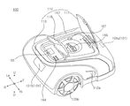
도 1은 본 발명의 일 실시예에 따른 잔디깎기 로봇(100)의 사시도이다.
도 2는 도 1의 잔디깎기 로봇(100)을 도킹(docking)시키는 도킹 기기(200)를 도시한 사시도이다.
도 3은 도 1의 잔디깎기 로봇(100)의 정면을 바라본 입면도이다.
도 4는 도 1의 잔디깎기 로봇(100)의 우측면을 바라본 입면도이다.
도 5는 도 1의 잔디깎기 로봇(100)의 하측면을 바라본 입면도이다.
도 6은 도 1의 잔디깎기 로봇(100)에서 케이스(112) 및 모듈 케이스(190)를 제거한 상태에서 상측면을 바라본 입면도이다.
도 7은 도 6의 잔디깎기 로봇(100)의 센서(170)이 배치된 부분을 도시한 부분 사시도이다.
도 8은, 도 1의 잔디깎기 로봇(100)을 도 7의 라인 S1-S1'를 따라 수직으로 자른 단면도이다.
도 9는, 도 8의 잔디깎기 로봇(100)을 라인 S2-S2'를 따라 수직으로 자른 단면도이다.1 is a perspective view of a
FIG. 2 is a perspective view showing a
3 is a front elevational view of the
4 is an elevational view of the right side of the
Fig. 5 is an elevational view of the
FIG. 6 is an elevational view of the
7 is a partial perspective view showing a portion where the
Fig. 8 is a cross-sectional view of the
Fig. 9 is a cross-sectional view of the
이하에서 언급되는 “전(F)/후(R)/좌(Le)/우(Ri)/상(U)/하(D)” 등의 방향을 지칭하는 표현은 도면에 표시된 바에 따라 정의하나, 이는 어디까지나 본 발명이 명확하게 이해될 수 있도록 설명하기 위한 것이며, 기준을 어디에 두느냐에 따라 각 방향들을 다르게 정의할 수도 있음은 물론이다.The expressions referring to directions such as " previous (F) / after (R) / left (Le) / right (R) / upper (U) / lower (D) " , It is to be understood that the present invention is to be clearly understood, and it goes without saying that the directions may be defined differently depending on where the reference is placed.
이하에서 언급되는 구성요소 앞에 ‘제 1, 제 2' 등의 표현이 붙는 용어 사용은, 지칭하는 구성요소의 혼동을 피하기 위한 것일 뿐, 구성요소 들 사이의 순서, 중요도 또는 주종관계 등과는 무관하다. 예를 들면, 제 1 구성요소 없이 제 2구성요소 만을 포함하는 발명도 구현 가능하다.The use of the term "first, second, etc." in front of the constituent elements mentioned below is intended to avoid confusion of the constituent elements referred to above, and is not related to the order, importance, . For example, an invention including only the second component without the first component is also feasible.
도 1 및 도 3 내지 도 9를 참고하여, 잔디깎기 로봇(100)은 외형을 형성하는 바디(110)를 포함한다. 바디(110)는 내부 공간을 형성한다. 잔디깎기 로봇(100)은 지면(주행면)에 대해 바디(110)를 운동시키는 구동 휠(wheel) 모듈(120)을 포함한다. 구동 휠 모듈(120)은, 각각 독립적으로 회전 가능하게 좌우에 구비되는 제 1휠(120a) 및 제 2휠(120b)을 포함한다. 잔디깎기 로봇(100)은 구동 휠 모듈(120)에 회전력을 제공하는 구동 모터 모듈(130)을 포함한다. 구동 모터 모듈(130)은, 제 1휠(120a)의 회전력을 제공하는 제 1모터(130a)와, 제 2휠(120b)의 회전력을 제공하는 제 2모터(130b)를 포함한다. 제 1모터(130a)는 제 2모터(130b)의 좌측에 배치된다. 잔디깎기 로봇(100)은 잔디를 깎기 위해 회전 가능하게 구비된 블레이드(140)를 포함한다. 잔디깎기 로봇(100)은 블레이드(140)의 회전력을 제공하는 블레이드 모터(150)를 포함한다. 잔디깎기 로봇(100)은 구동 모터 모듈(130)에 전원을 공급하는 배터리(Bt)를 포함한다. 배터리(Bt)는 블레이드 모터(150)에 전원을 공급할 수 있다. Referring to Figs. 1 and 3 to 9, the
잔디깎기 로봇(100)은 바디(110)의 상기 내부 공간에 배치되는 센서(170)을 포함한다. 상기 센서(170)은 자이로(gyro) 센싱 기능 및 자기장 센싱 기능을 구비한다. 상기 센서(170)은 가속도 센싱 기능을 더 구비할 수 있다.The
도 6 내지 도 9를 참고하여, 상기 제 1휠(120a)은 좌우로 연장된 가상의 휠축(Ow)을 중심으로 회전 가능하게 구비될 수 있다. 상기 제 2휠(120b)은 상기 휠축(Ow)을 중심으로 회전 가능하게 구비될 수 있다. 그러나, 반드시 이에 제한될 필요는 없으며, 상기 제 1휠의 회전축과 상기 제 2휠의 회전축이 서로 각을 이루며 교차하게 구비되거나, 상기 제 1휠의 회전축과 상기 제 2휠의 회전축이 잔디깎기 로봇의 이동 제어에 따라 변경 가능하게 구비될 수도 있다. 즉, 본 실시예에서는 제 1휠(120a)의 중심 및 제 2휠(120b)의 중심을 이어주는 가상의 직선이 상기 휠축(Ow)이나, 제 1휠(120a)의 중심 및 제 2휠(120b)의 중심을 이어주는 가상의 직선이 제 1휠(120a)의 회전축과 다르고 제 2휠(120b)의 회전축과 다를 수도 있다.Referring to FIGS. 6 to 9, the
상기 휠축(Ow)은 제 1휠(120a) 및 제 2휠(120b)의 회전축의 위치를 설명하기 위한 가상의 축(Axis)으로서, 샤프트(shaft) 등의 실제 부품을 지칭하는 것이 아니다. 제 1휠(120a) 및 제 2휠(120b)이 상기 휠축(Ow)을 중심으로 회전되게 하기 위하여, 본 실시예에서는 제 1휠(120a) 및 제 2휠(120b)이 각각 제 1모터(130a)의 회전축 및 제 2모터(130b)의 회전축에 직접 연결되나, 제 1휠(120a) 및 제 2휠(120b)에 샤프트 등의 부품이 연결될 수도 있고, 기어나 체인 등에 의해 모터(130a, 130b)의 회전력이 휠(120a, 120b)에 전달되게 구현될 수도 있다.The wheel axis Ow is a virtual axis Axis for describing the positions of the rotation axes of the
도 6 내지 도 9를 참고하여, 본 발명의 구성을 설명하기 위한 가상의 평면(Plane)들을 정의하면 다음과 같다. 다음의 가상의 평면들(V1, V2, V3, V4a, V4b, V5a, V5b, H1a, H1b, H2, H3)은 실제 부품이나 실제의 평면을 지칭하는 것이 아니다. 여기서, 수직(vertically) 배치된 평면은 상하 방향 축(U, D)에 평행한 평면을 의미하고, 수평(horizontally) 배치된 평면은 전후 방향 축(F, R) 및 좌우 방향 축(Le, Ri)에 평행한 평면을 의미한다.6 to 9, virtual planes for describing the configuration of the present invention are defined as follows. The following virtual planes V1, V2, V3, V4a, V4b, V5a, V5b, H1a, H1b, H2, H3 do not refer to actual components or actual planes. Here, the vertically arranged plane means a plane parallel to the vertical axes U and D, and the horizontally disposed plane means the front and rear axes F and R and the left and right axes Le and Ri ). ≪ / RTI >
상기 제 1휠(120a)의 중심 및 상기 제 2휠(120b)의 중심을 지나며 수직 배치된 가상의 휠축 평면 가상의 휠축 평면(V1)이 정의된다. 상기 휠축 평면(V1)은 상기 휠축(Ow)을 포함하는 평면일 수 있다. 블레이드 모터(150)의 후(R)단(end)에 접하고 수직 배치된 가상의 블레이드 모터 후단 평면(V2)이 정의된다. 배터리(Bt)의 전(F)단(end)에 접하고 수직 배치된 가상의 배터리 전단 평면(V3)이 정의된다. 제 1휠(120a)의 전단과 제 2휠(120b)의 전단에 접하고 수직 배치된 가상의 휠 전단 평면(V4a)이 정의된다. 제 1휠(120a)의 후단과 제 2휠(120b)의 후단에 접하고 수직 배치된 가상의 휠 후단 평면(V4b)이 정의된다. 제 1모터(130a)의 우(Ri)단(end)에 접하고 수직 배치된 가상의 제 1모터 우단 평면(V5a)이 정의된다. 제 2모터(130b)의 좌(Le)단(end)에 접하고 수직 배치된 가상의 제 2모터 좌단 평면(V5b)이 정의된다. 제 1모터(130a)의 상(U)단(end)에 접하고 수평 배치된 가상의 제 1모터 상단 평면(H1a)가 정의된다. 제 2모터(130b)의 상단에 접하고 수평 배치된 가상의 제 2모터 상단 평면(H1b)이 정의된다. 제 1모터 상단 평면(H1a) 및 제 2모터 상단 평면(H1b)은 동일 평면을 구성할 수 있다. 구동 모터 모듈(130)의 상단에 접하고 수평 배치된 구동 모터 상단 평면(H1a, H1b)이 정의될 수 있다. 블레이드 모터(150)의 상단에 접하고 수평 배치된 가상의 블레이드 모터 상단 평면(H2)이 정의된다. 배터리(Bt)의 상단에 접하고 수평 배치된 가상의 배터리 상단 평면(H3)이 정의된다.A hypothetical wheel axis plane imaginary wheel axis plane V1 vertically arranged passing through the center of the
도 1 및 도 3 내지 도 5를 참고하여, 잔디깎기 로봇(100)은 전방의 장애물을 감지하는 장애물 감지부(161)를 포함한다. 복수의 장애물 감지부(161a, 161b, 161c)가 구비될 수 있다. 장애물 감지부(161)는 바디(110)의 전방면에 배치된다. 장애물 감지부(161)는 프레임(111)보다 상측에 배치된다.Referring to Figs. 1 and 3 to 5, the
잔디깎기 로봇(100)은 비(rain)를 감지하는 레인 감지부(미도시)를 포함할 수 있다. 상기 레인 감지부는 케이스(112)에 배치될 수 있다. 상기 레인 감지부는 프레임(111)보다 상측에 배치될 수 있다.The
잔디깎기 로봇(100)은 외부의 원격 신호를 수신하는 원격 신호 수신부(101)를 포함한다. 외부의 리모트 컨트롤러에 의한 원격 신호가 송신되면, 원격 신호 수신부(101)가 상기 원격 신호를 수신할 수 있다. 예를 들어, 상기 원격 신호는 적외선 신호일 수 있다. 원격 신호 수신부(101)에 의해 수신된 신호는 제어부(163)에 의해 처리될 수 있다.The
복수의 원격 신호 수신부(101)가 구비될 수 있다. 복수의 원격 신호 수신부(101)는, 바디(110)의 전방부에 배치된 제 1원격 신호 수신부(101a)와, 바디(110)의 후방부에 배치된 제 2원격 신호 수신부(101b)를 포함할 수 있다. 제 1원격 신호 수신부(101a)는 전방으로부터 송신되는 원격 신호를 수신한다. 제 2원격 신호 수신부(101b)는 후방으로부터 송신되는 원격 신호를 수신한다.A plurality of remote
잔디깎기 로봇(100)은 제 1휠(120a) 및 제 2휠(120b)의 전방에 배치되는 보조 휠(162)을 포함한다. 보조 휠(162)은 블레이드(140)의 전방에 배치될 수 있다. 보조 휠(162)은 모터에 의한 구동력을 전달받지 않는 휠로서, 바디(110)를 지면에 대해 보조적으로 지지하는 역할을 한다. 보조 휠(162)의 회전축을 지지하는 캐스터(107)은 수직한 축에 대해 회전 가능하게 프레임(111)에 결합된다. 좌측에 배치된 제 1보조 휠(162a)과 우측에 배치된 제 2보조 휠(162b)이 구비될 수 있다.The
잔디깎기 로봇(100)은 사용자의 각종 지시를 입력할 수 있는 입력부(164)를 포함할 수 있다. 입력부(164)는 버튼, 다이얼, 터치형 디스플레이 등을 포함할 수 있다. 입력부(164)는 음성 인식을 위한 마이크(미도시)를 포함할 수 있다. 본 실시예에서, 케이스(112)의 상측부에 다수의 버튼이 배치된다.The
잔디깎기 로봇(100)은 사용자에게 각종 정보를 출력해주는 출력부(165)를 포함할 수 있다. 출력부(165)는 시각적 정보를 출력하는 디스플레이 모듈(165)을 포함할 수 있다. 출력부(165)는 청각적 정보를 출력하는 스피커(미도시)를 포함할 수 있다. The
본 실시예에서, 디스플레이 모듈(165)은 상측 방향으로 화상을 출력한다. 디스플레이 모듈(165)은 케이스(112)의 상측부에 배치된다. 일 예로, 디스플레이 모듈(165)은 액정 표시(LCD: Thin film transistor liquid-crystal display) 패널을 포함할 수 있다. 그 밖에도, 디스플레이 모듈(165)은, 플라스마 디스플레이 패널(plasma display panel) 또는 유기 발광 디스플레이 패널(organic light emitting diode display panel) 등의 다양한 디스플레이 패널을 이용하여, 구현될 수 있다.In this embodiment, the
잔디깎기 로봇(100)은 외부의 기기(단말기 등), 서버, 공유기 등과 통신하기 위한 통신부(미도시)를 포함할 수 있다. 상기 통신부는 통신하고자 하는 다른 장치 또는 서버의 통신 방식이 무엇인지에 따라 달라질 수 있다.The
잔디깎기 로봇(100)은 지면에 대한 블레이드(140)의 높이를 변경 가능하게 구비되어, 잔디의 깎는 높이를 변경할 수 있다. 잔디깎기 로봇(100)은 사용자가 상기 블레이드(140)의 높이를 변경하기 위한 높이 조절부(166)를 포함한다. 높이 조절부(166)는 회전 가능한 다이얼을 포함하여, 상기 다이얼을 회전시킴으로써 상기 블레이드(140)의 높이를 변경시킬 수 있다.The
잔디깎기 로봇(100)은 블레이드(140)의 높이의 수준을 표시해주는 높이 표시부(167)를 포함한다. 높이 조절부(166)의 조작에 따라 블레이드(140)의 높이가 변경되면, 높이 표시부(167)가 표시하는 높이 수준도 같이 변경된다. 예를 들어, 높이 표시부(167)에는 현재의 블레이드(140) 높이 상태로 잔디깎기 로봇(100)이 잔디 깎기를 수행한 후 예상되는 잔디의 높이 값이 표시될 수 있다.The
잔디깎기 로봇(100)은 GPS(Global Positioning System) 신호를 감지하기 위해 구비되는 GPS 보드(168)를 포함한다. GPS 보드(168)는 PCB일 수 있다.The
잔디깎기 로봇(100)은 도킹 기기(200)에 도킹 시, 도킹 기기(200)와 연결되는 도킹 삽입부(169)를 포함한다. 도킹 삽입부(169)는 도킹 기기(200)의 도킹 연결부(210)가 삽입되도록 함몰되게 구비된다. 도킹 삽입부(169)는 바디(110)의 정면부에 배치된다. 도킹 삽입부(169)와 도킹 연결부(210)의 연결에 의해, 잔디깎기 로봇(100)이 충전시 정확한 위치가 안내될 수 있다.The
잔디깎기 로봇(100)은, 도킹 삽입부(169)가 도킹 연결부(210)에 삽입된 상태에서, 후술할 충전 단자(211)와 접촉 가능한 위치에 배치되는 충전 대응 단자(102)를 포함할 수 있다. 충전 대응 단자(102)는 한 쌍의 충전 단자(211a, 211b)와 대응되는 위치에 배치되는 한 쌍의 충전 대응 단자(102a, 102b)를 포함할 수 있다. 한 쌍의 충전 대응 단자(102a, 102b)는 도킹 삽입부(169)를 사이에 두고 좌우로 배치될 수 있다.The
도킹 삽입부(158)와 한 쌍의 충전 단자(211a, 211b)를 개폐 가능하게 덮어주는 단자 커버(미도시)가 구비될 수 있다. 이동 로봇()의 주행시, 상기 단자 커버는 상기 도킹 삽입부(158)와 한 쌍의 충전 단자(211a, 211b)를 가려줄 수 있다. 이동 로봇()이 도킹 기기()와 연결시, 상기 단자 커버가 열려 상기 도킹 삽입부(158)와 한 쌍의 충전 단자(211a, 211b)가 노출될 수 있다.A terminal cover (not shown) may be provided to cover the docking insert 158 and the pair of charging
잔디깎기 로봇(100)은 자율 주행을 제어하는 제어부(163)를 포함한다. 제어부(163)는 장애물 감지부(161)의 신호를 처리할 수 있다. 제어부(163)는 GPS 보드(168)의 신호를 처리할 수 있다. 제어부(163)는 상기 센서(170)의 신호를 처리할 수 있다. 제어부(163)는 입력부(164)의 신호를 처리할 수 있다.The
제어부(163)는 제 1모터(130a) 및 제 2모터(130b)의 구동을 제어할 수 있다. 제어부(163)는 블레이드 모터(150)의 구동을 제어할 수 있다. 제어부(163)는 출력부(165)의 출력을 제어할 수 있다.The
제어부(163)는 바디(110)의 상기 내부 공간에 배치되는 메인 보드(163)를 포함한다. 메인 보드(163)는 PCB를 의미한다.The
한편, 도 2를 참고하여, 도킹 기기(200)는 바닥에 배치되는 도킹 베이스(230)와, 도킹 베이스(230)의 전방부에서 상측으로 돌출된 도킹 지지부(220)를 포함한다. 잔디깎기 로봇(100)의 충전시, 도킹 삽입부(169)에 삽입되는 도킹 연결부(210)를 포함한다. 도킹 연결부(210)는 도킹 지지부(220)에서 후방으로 돌출될 수 있다.2, the
도킹 연결부(210)는 상하 방향의 두께가 좌우 방향의 폭보다 작게 형성될 수 있다. 도킹 연결부(210)의 좌우 방향 폭은 후측으로 갈수록 좁아지게 형성될 수 있다. 상측에서 바라볼 때, 도킹 연결부(210)는 전체적으로 사다리꼴이다. 도킹 연결부(210)는 좌우 대칭된 형상으로 형성된다. 도킹 연결부(210)의 후방부는 자유단을 형성하고, 도킹 연결부(210)의 전방부는 도킹 지지부(220)에 고정된다. 도킹 연결부(210)의 후방부는 라운드진 형상으로 형성될 수 있다.The
도킹 연결부(210)가 도킹 삽입부(169)에 완전히 삽입되면, 잔디깎기 로봇(100)의 도킹 기기에 의한 충전이 이루어질 수 있다.When the
도킹 기기(200)는 잔디깎기 로봇(100)을 충전시키기 위한 충전 단자(211)를 포함한다. 충전 단자(211)와 잔디깎기 로봇(100)의 충전 대응 단자(102)가 접촉하여, 도킹 기기(200)로부터 잔디깎기 로봇(100)으로 충전을 위한 전원이 공급될 수 있다.The
충전 단자(211)는 후측을 바라보는 접촉면을 포함하고, 충전 대응 단자(102)는 전방을 바라보는 접촉 대응면을 포함한다. 충전 단자(211)의 상기 접촉면과 충전 대응 단자(102)의 상기 접촉 대응면이 접촉함으로써, 도킹 기기(200)의 전원이 잔디깎기 로봇(100) 연결된다.The charging
충전 단자(211)는 +극 및 -극을 형성하는 한 쌍의 충전 단자(211a, 211b)를 포함할 수 있다. 제 1충전 단자(211a)는 제 1충전 대응 단자(102a)와 접촉하게 구비되고, 제 2충전 단자(211b)는 제 2충전 대응 단자(102b)에 접촉하게 구비된다. The charging
한 쌍의 충전 단자(211a, 211b)는 도킹 연결부(210)를 사이에 두고 배치될 수 있다. 한 쌍의 충전 단자(211a, 211b)는 도킹 연결부(210)의 좌우에 배치될 수 있다.The pair of charging
도킹 베이스(230)는 잔디깎기 로봇(100)의 구동 휠 모듈(120) 및 보조 휠(162)이 올라서는 휠 가드(232)를 포함한다. 휠 가드(232)는, 제 1보조 휠(162)의 이동을 안내하는 제 1휠 가드(232a)와, 제 2보조 휠(162)의 이동을 안내하는 제 2휠 가드(232b)를 포함한다. 제 1휠 가드(232a)와 제 2휠 가드(232b)의 사이에는 상측으로 볼록한 중앙 베이스(231)가 배치된다. 도킹 베이스(230)는 제 1휠(120a) 및 제 2휠(120b)의 미끄럼을 방지하기 위한 슬립 방지부(234)를 포함한다. 슬립 방지부(234)는 상측으로 돌출된 복수의 돌기를 포함할 수 있다.The
다시, 도 1 및 도 3 내지 도 9를 참고하여, 바디(110)는 상기 제 1모터(130a) 및 제 2모터(130b)가 고정되는 프레임(111)을 포함한다. 프레임(111)에 상기 블레이드 모터(150)가 고정된다. 프레임(111)은 메인 보드(163), 후술할 모듈 지지부(180) 및 센서(170)를 지지한다. 프레임(111)은 모듈 케이스(190)를 지지한다. 프레임(111)은 배터리(Bt)를 지지한다. 프레임(111)은 그 밖에도 다른 여러 부품들을 지지하는 뼈대 구조를 제공한다. 프레임(111)은 보조 휠(162) 및 구동 휠 모듈(120)에 의해 지지된다.Referring again to FIGS. 1 and 3 to 9, the
바디(110)는 블레이드(140)의 양측방에서 사용자의 손가락이 블레이드(140)로 진입하는 것을 차단하기 위한 측방 차단부(111a)를 포함한다. 측방 차단부(111a)는 프레임(111)에 고정된다. 측방 차단부(111a)는 프레임(111)의 다른 부분의 하측면에 비해 하측으로 돌출되어 배치된다. 측방 차단부(111a)는 휠 모듈(120)과 보조 휠(162)의 사이 공간의 상측부를 커버하며 배치된다.The
한 쌍의 측방 차단부(111a-1, 111a-2)가 블레이드(140)를 사이에 두고 좌우로 배치된다. 측방 차단부(111a)는 블레이드(140)로부터 소정 거리 이격되어 배치된다. A pair of
측방 차단부(111a)의 전방면(111af)은 라운드지게 형성된다. 전방면(111af)은 측방 차단부(111a)의 하측면에서부터 전방으로 갈수록 라운드지게 상측으로 꺾이는 표면을 형성한다. 이러한 전방면(111af)의 형상을 이용하여, 잔디깎기 로봇(100)이 전방으로 이동할 때 측방 차단부(111a)는 소정 기준 이하의 하부 장애물을 쉽게 타고 넘어갈 수 있다.The front face 111af of the
바디(110)는 블레이드(140)의 전방에서 사용자의 손가락이 블레이드(140)로 진입하는 것을 차단하기 위한 전방 차단부(111b)를 포함한다. 전방 차단부(111b)는 프레임(111)에 고정된다. 전방 차단부(111b)는 한 쌍의 보조 휠(162a, 162b)의 사이 공간의 상측부의 일부를 커버하며 배치된다.The
전방 차단부(111b)는 프레임(111)의 다른 부분의 하측면에 비해 하측으로 돌출되는 돌출 리브(111ba)를 포함한다. 돌출 리브(111ba)는 전후 방향으로 연장된다. 돌출 리브(111ba)의 상단부는 프레임(111)에 고정되고, 돌출 리브(111ba)의 하단부는 자유단을 형성한다.The
복수의 돌출 리브(111ba)가 좌우 방향으로 이격되어 배치될 수 있다. 복수의 돌출 리브(111ba)가 서로 평행하게 배치될 수 있다. 인접하는 2개의 돌출 리브(111ba) 사이에 틈이 형성된다. A plurality of protruding ribs 111ba can be arranged so as to be spaced laterally. A plurality of protruding ribs 111ba can be arranged parallel to each other. A gap is formed between two adjacent protruding ribs 111ba.
돌출 리브(111ba)의 전방면은 라운드지게 형성된다. 돌출 리브(111ba)의 상기 전방면은 돌출 리브(111ba)의 하측면에서부터 전방으로 갈수록 라운드지게 상측으로 꺾이는 표면을 형성한다. 이러한 돌출 리브(111ba)의 상기 전방면의 형상을 이용하여, 잔디깎기 로봇(100)이 전방으로 이동할 때 돌출 리브(111ba)는 소정 기준 이하의 하부 장애물을 쉽게 타고 넘어갈 수 있다.The front surface of the protruding rib 111ba is rounded. The front surface of the protruding rib 111ba forms a surface that is rounded upward toward the front from the bottom surface of the protruding rib 111ba. Using the shape of the front surface of the protruding rib 111ba, when the
전방 차단부(111b)는 강성을 보조하는 보조 리브(111bb)를 포함한다. 인접하는 2개의 돌출 리브(111ba)의 상단부의 사이에, 전방 차단부(111b)의 강성을 보강하기 위한 보조 리브(111bb)가 배치된다. 보조 리브(111bb)는 하측으로 돌출되고 격자형으로 연장되어 형성될 수 있다.The
프레임(111)에는 보조 휠(162)을 회전 가능하게 지지하는 캐스터(107)가 배치된다. 캐스터(107)는 프레임(111)에 대해 회전 가능하게 배치된다. 캐스터(107)는 수직 축을 중심으로 회전 가능하게 구비된다. 캐스터(107)는 프레임(111)의 하측에 배치된다. 한 쌍의 보조 휠(162)에 대응하는 한 쌍의 캐스터(107)가 구비된다.In the
프레임(111)과 캐스터(107)를 연결시키는 캐스터 연결부(103)가 구비된다. 캐스터 연결부(103)는 프레임(111)을 상하로 관통하며 배치될 수 있다. 캐스터 연결부(103)는 프레임(111) 및 캐스터(107) 중 어느 하나에 고정되고 다른 하나에 회전 가능하게 연결될 수 있다. 한 쌍의 캐스터(107)에 대응하는 한 쌍의 캐스터 연결부(103a, 103b)가 구비된다.And a
바디(110)는 프레임(111)을 상측에서 덮어주는 케이스(112)를 포함한다. 케이스(112)는 잔디깎기 로봇(100)의 상측면 및 전/후/좌/우 측면을 형성한다. The
케이스(112)의 측면부에는 내측으로 함몰된 함몰부(112a)가 형성될 수 있다. 한 쌍의 함몰부(112a)가 케이스(112)의 양측 표면에 형성될 수 있다. 함몰부(112a)는, 후방부에서 전방부 방향으로 갈수록 함몰 깊이가 점점 깊어지는 부분을 포함한다.A
바디(110)는 케이스(112)를 프레임(111)에 고정시키는 케이스 연결부(104)를 포함한다. 케이스 연결부(104)의 상단에 케이스(112)가 고정된다. 케이스 연결부(104)의 상측부는 프레임(111)의 상측으로 노출된다.The
케이스 연결부(104)는 프레임(111)에 유동 가능하게 배치된다. 케이스 연결부(104)는 프레임(111)에 대해 상하 방향으로만 유동 가능하게 배치될 수 있다. 케이스 연결부(104)는 소정 범위 내에서만 유동 가능하게 구비된다. 케이스 연결부(104)는 케이스(112)와 일체로 유동한다. 이에 따라, 케이스(112)는 프레임(111)에 대해 유동이 가능하다.The
한 쌍의 케이스 연결부(104a, 104)가 프레임(111)의 양측에 배치될 수 있다. 한 쌍의 케이스 연결부(104)는 프레임(111)의 전방부에 배치될 수 있다.A pair of
프레임(111)에는 상기 케이스 연결부(104)의 유동을 감지하는 유동 감지 센서(미도시)가 구비된다. 이를 통해, 프레임(111)에 대해 케이스(112)가 상측으로 들어올려지면, 상기 케이스 연결부(104)가 상측으로 유동하게 되고, 상기 유동 감지 센서가 상기 케이스(112)의 들어올려짐을 감지하게 된다. 상기 유동 감지 센서가 상기 케이스(112)의 들어올려짐을 감지하면, 제어부(163)는 블레이드(140)의 동작을 정지시키도록 제어할 수 있다. 예를 들어, 사용자가 케이스(112)를 들어올리거나 상당한 크기의 하부 장애물이 케이스(112)를 들어올리는 상황 발생시, 상기 유동 감지 센서가 이를 감지할 수 있다.The
바디(110)는 전방부에 배치되는 범퍼(112b)를 포함한다. 범퍼(112b)는 외부의 장애물과 접촉시 충격을 흡수해 주는 기능을 수행한다. 범퍼(112b) 정면부에는, 후측으로 함몰되어 좌우 방향으로 길게 형성된 범퍼 홈(112h)이 형성될 수 있다. 복수의 범퍼 홈(112h)이 상하 방향으로 이격되어 배치될 수 있다. 돌출 리브(111ba)의 하단이 보조 리브(111bb)의 하단보다 더 낮은 위치에 배치된다.The
범퍼(112b)는 전방면 및 좌우 측면이 서로 연결되어 형성된다. 범퍼(112b)의 전방면 및 측면은 라운드지게 연결된다.The
바디(110)는 범퍼(112b)의 외표면을 감싸며 배치되는 범퍼 보조부(112c)를 포함할 수 있다. 범퍼 보조부(112c)는 범퍼(112b)의 전방면의 하부 및 좌우 측면의 하부를 감싸준다. 범퍼 보조부(112c)는 범퍼(112b)의 전방면 및 좌우 측면의 하반부를 덮어줄 수 있다. The
범퍼 보조부(112c)의 전단면은 범퍼(112b)의 전단면보다 전방에 배치된다. 범퍼 보조부(112c)는 범퍼(112b)의 표면에서돌출된 표면을 형성한다. The front end surface of the bumper
범퍼 보조부(112c)는 고무 등 충격 흡수에 유리한 재질로 형성될 수 있다. 범퍼 보조부(112c)는 플렉서블한 재질로 형성될 수 있다.The bumper
범퍼 보조부(112c)는 범퍼(112b)에 결합된다. 범퍼 보조부(112c)는 범퍼(112b)에 결합되는 범퍼 결합부(112ca)를 포함한다. 범퍼 결합부(112ca)는 범퍼 보조부(112c)에서 범퍼(112b)의 내측 방향으로 돌출되어, 범퍼(112b)의 표면을 관통하게 배치될 수 있다. 범퍼 결합부(112ca)는 후크를 구비하여, 범퍼(112b)에 후크 결합된다. 도 5에는, 범퍼 결합부(112ca)가 범퍼(112b)를 관통하여, 범퍼 결합부(112ca)의 돌출 말단이 범퍼(112b)이 배면에 배치되는 모습이 도시된다.The bumper
프레임(111)에는, 범퍼(112b)가 고정되는 유동 고정부(105)가 구비된다. 유동 고정부(105)는 프레임(111)의 상측으로 돌출되게 배치될 수 있다. 유동 고정부(105)의 상단부에 범퍼(112b)가 고정된다. The
범퍼(112b)는 프레임(111)에 대해 소정 범위 내 유동 가능하게 배치된다. 범퍼(112b)는 유동 고정부(105)에 고정되어 유동 고정부(105)와 일체로 유동한다.The
유동 고정부(105)는 프레임(111)에 유동 가능하게 배치된다. 본 실시예에서, 유동 고정부(105)는 프레임(111)에 소정 범위 내 회전 가능하게 배치된다. 유동 고정부(105)의 돌출 방향으로 연장된 가상의 회전축을 중심으로, 유동 고정부(105)가 프레임(111)에 대해 회전 가능하게 구비된다. 이에 따라, 범퍼(112b)는 프레임(111)에 대해 유동 고정부(105)와 일체로 회전 가능하게 구비된다.The
유동 고정부(105)의 회전을 감지하는 회전 감지 센서(미도시)가 구비될 수 있다. 예를 들어, 유동 고정부(105)의 하부의 일측에 자석을 배치하고, 프레임(111)에 상기 자석의 자기장의 변화를 감지하는 자기장 센싱부를 배치할 수 있다. 유동 고정부(111)가 회전시 상기 자기장 센싱부는 상기 자석의 자기장 변화를 감지함으로써, 유동 고정부(105)의 회전을 감지하는 상기 회전 감지 센서가 구현될 수 있다.(Not shown) for sensing the rotation of the
범퍼(112b)가 외부의 장애물에 충돌하면, 범퍼(112b)와 일체로 유동 고정부(105)가 회전한다. 상기 회전 감지 센서가 유동 고정부(105)의 회전을 감지함으로써, 범퍼(112b)의 충격을 감지할 수 있다.When the
바디(110)는 손잡이(113)를 포함한다. 손잡이(113)는 케이스(112)의 후측부에 배치될 수 있다.The
바디(110)는 배터리(Bt)를 인출입하기 위한 배터리 투입부(114)를 포함한다. 배터리 투입부(114)는 프레임(111)의 하측면에 배치될 수 있다. 배터리 투입부(114)는 프레임(111)의 후측부에 배치될 수 있다.The
바디(110)는 잔디깎기 로봇(100)의 전원을 On/Off하기 위한 전원 스위치(115)를 포함한다. 전원 스위치(115)는 프레임(111)의 하측면에 배치될 수 있다.The
바디(110)는 블레이드(140)의 중앙부의 하측을 가려주는 블레이드 보호부(116)를 포함한다. 블레이드 보호부(116)는 블레이드(140)의 원심 방향 부분의 날이 노출되되 블레이드(140)의 중앙부가 가려지도록 구비된다.The
바디(110)는 높이 조절부(166)및 높이 표시부(167)가 배치된 부분을 개폐시키는 제 1개폐부(117)를 포함한다. 제 1개폐부(117)는 케이스(112)에 힌지 결합되어, 열림 동작 및 닫힘 동작이 가능하게 구비된다. 제 1개폐부(117)는 케이스(112)의 상측면에 배치된다.The
제 1개폐부(117)는 판형으로 형성되어, 닫힘 상태에서 높이 조절부(166) 및 높이 표시부(167)의 상측을 덮어준다.The first opening and closing
바디(110)는 디스플레이 모듈(165) 및 입력부(164)가 배치된 부분을 개폐시키는 제 2개폐부(118)를 포함한다. 제 2개폐부(118)는 케이스(112)에 힌지 결합되어, 열림 동작 및 닫힘 동작이 가능하게 구비된다. 제 2개폐부(118)는 케이스(112)의 상측면에 배치된다. 제 2개폐부(118)는 제 1개폐부(117)의 후방에 배치된다.The
제 2개폐부(118)는 판형으로 형성되어, 닫힘 상태에서 디스플레이 모듈(165) 및 입력부(164)를 덮어준다. The second opening and closing
제 2개폐부(118)의 상기 열림 가능 각도는 상기 제 1개폐부(117)의 상기 열림 가능 각도에 비해 작도록, 기설정된다. 이를 통해, 제 2개폐부(118)의 열림 상태에서도, 사용자가 제 1개폐부(117)를 쉽게 열게 해주고, 사용자가 쉽게 높이 조절부(166)를 조작할 수 있게 해준다. 또한, 제 2개폐부(118)의 열림 상태에서도, 사용자가 높이 표시부(167)의 내용을 시각적으로 확인할 수 있게 해준다.The openable angle of the second opening and closing
예를 들어, 제 1개폐부(117)의 열림 가능 각도는 닫힘 상태를 기준으로 약 80 내지 90도 정도가 되도록 구비될 수 있다. 예를 들어, 제 2개폐부(118)의 열림 가능 각도는 닫힘 상태를 기준으로 약 45 내지 60도 정도가 되도록 구비될 수 있다.For example, the openable angle of the first opening and closing
제 1개폐부(117)는 전단부를 중심으로 후단부가 상측으로 들어올려져 열림 동작하고, 제 2개폐부(118)는 전단부를 중심으로 후단부가 상측으로 들어올려져 열림 동작한다. 이를 통해, 잔디 깎기 로봇(100)이 전방으로 이동할 때에도 안전한 지역인 잔디 깎기 로봇(100)의 후방에서, 사용자가 제 1개폐부(117) 및 제 2개폐부(118)를 여닫을 수 있다. 또한, 이를 통해, 제 1개폐부(117)의 열림 동작과 제 2개폐부(118)의 열림 동작이 서로 간섭되지 않게 할 수 있다.The rear end of the first opening /
제 1개폐부(117)의 전단부에서 좌우 방향으로 연장된 회전축을 중심으로, 제 1개폐부(117)가 케이스(112)에 대해 회전 동작 가능하게 구비될 수 있다. 제 2개폐부(118)의 전단부에서 좌우 방향으로 연장된 회전축을 중심으로, 제 2개폐부(118)가 케이스(112)에 대해 회전 동작 가능하게 구비될 수 있다.The first opening and closing
한편, 잔디깎기 로봇(100)은 상기 제 1개폐부(117) 및 상기 제 2개폐부(118) 중 적어도 하나의 개폐 여부를 감지하는 개폐 감지부(미도시)를 포함할 수 있다. 상기 개폐 감지부는 케이스(112)에 배치될 수 있다. 상기 개폐 감지부는 프레임(111)보다 상측에 배치될 수 있다.The
한편, 프레임(111)에는 케이블(미도시)이 연결되는 케이블 연결부(106)를 포함한다. 케이블 연결부(106)는 복수의 케이블(미도시)이 각각 연결되는 복수의 단자를 포함할 수 있다.Meanwhile, the
상기 복수의 단자는, 상기 장애물 감지부(161)의 감지 정보를 전달하는 케이블이 연결되는 제 1단자(106a)를 포함할 수 있다. 상기 복수의 단자는, 상기 레인 감지부의 감지 정보를 전달하는 케이블이 연결되는 제 2단자(106b)를 포함할 수 있다. 상기 복수의 단자는, 상기 개폐 감지부의 감지 정보를 전달하는 케이블이 연결되는 제 3단자(106c)를 포함할 수 있다. 상기 복수의 단자는, 상기 입력부(164)의 입력 정보를 전달하는 케이블이 연결되는 제 4단자(106d)를 포함할 수 있다.The plurality of terminals may include a first terminal 106a to which a cable for transmitting sensing information of the
상기 장애물 감지부(161), 상기 레인 감지부, 상기 개폐 감지부 및 상기 입력부(164)는 프레임(111)보다 상측에 배치되고, 상기 케이블 연결부(106)는 프레임(111)의 상측면에 배치된다. 상기 복수의 단자로 전달된 신호(감지 정보, 입력 정보)는, 추가적으로 연결되는 케이블 등에 의해 제어부(163)로 전달된다.The
상기 복수의 단자는 프레임의 일 부분에 집중 배치될 수 있다. 상측에서 바라볼 때, 상기 복수의 단자는 케이블 가이드(108)에 의해 둘러싸진다. 케이블 가이드(108)는 프레임(111)에서 상측으로 돌출된 리브 형상으로 형성될 수 있다. 케이블 가이드(108)는 상측에서 바라볼 때 사각 형상으로 연장되되, 일측면의 일부에 홈을 형성시킬 수 있다. 상기 케이블은 케이블 가이드(108)의 상기 홈에 삽입되어, 케이블의 배치를 안내받을 수 있다.The plurality of terminals may be disposed concentrically on a part of the frame. When viewed from above, the plurality of terminals are surrounded by a
구동 휠(wheel) 모듈(120)은 좌측에 배치되는 제 1휠(120a) 및 우측에 배치되는 제 2휠(120b)을 포함한다. 제 1휠(120a)은 제 2휠(120b)보다 좌측에 배치된다. 제 1휠(120a) 및 제 2휠(120b)은 좌우로 이격 배치된다. 제 1휠(120a) 및 제 2휠(120b)은 바디(110)의 후측 하방부에 배치된다.The
제 1휠(120a) 및 제 2휠(120b)은 바디(110)가 지면에 대해 회전 운동 및 전진 운동이 가능하도록 각각 독립적으로 회전 가능하게 구비된다. 예를 들어, 제 1휠(120a)과 제 2휠(120b)이 같은 회전 속도로 회전할 때, 바디(110)는 지면에 대해 전진 운동할 수 있다. 예를 들어, 제 1휠(120a)의 회전 속도가 제 2휠(120b)의 회전 속도보다 빠르거나 제 1휠(120a)의 회전 방향 및 제 2휠(120b)의 회전 방향이 서로 다를 때, 바디(110)는 지면에 대해 회전 운동을 할 수 있다.The
제 1휠(120a) 및 제 2휠(120b)은 보조 휠(162)보다 크게 형성될 수 있다. 제 1휠(120a)의 중심부에 제 1모터(130a)의 축이 고정될 수 있고, 제 2휠(120b)의 중심부에 제 2모터(130b)의 축이 고정될 수 있다.The
휠(120)은 지면과 접촉하는 휠 외주부(122)를 포함한다. 예를 들어, 휠 외주부(122)는 타이어일 수 있다. 휠 외주부(122)에는 지면과의 마찰력을 상승시키기 위한 복수의 돌기가 형성될 수 있다.The
휠(120)은 휠 외주부(122)를 고정시키고 모터(130)의 동력을 전달받는 휠 프레임(미도시)을 포함할 수 있다. 상기 휠 프레임의 중앙부에 모터(130)의 축이 고정되어, 회전력을 전달받을 수 있다. 휠 외주부(122)는 상기 휠 프레임의 둘레를 감싸며 배치된다.The
휠(120)은 상기 휠 프레임의 외측 표면을 덮어주는 휠 커버(121)를 포함한다. 휠 커버(121)는 상기 휠 프레임을 기준으로 모터(130)가 배치된 방향의 반대 방향(이하 '외측 방향'이라 지칭함)에 배치된다. 휠 커버(121)는 휠 외주부(122)의 중앙부에 배치된다. 휠 커버(121)의 중심을 휠 축(Ow)이 관통하게 구비될 수 있다. The
휠 커버(121)는 휠 축(Ow)이 관통하는 중앙부(121a)를 포함한다. 측면에서 바라볼 때, 상기 중앙부(121a)는 원형으로 형성된다. The
휠 커버(121)는 중앙부(121a)에서 상기 휠 축(Ow)으로부터 멀어지는 방향으로 연장되는 원심부(121b)를 포함한다. 복수의 원심부(121b)가 상기 휠 축(Ow)을 중심으로 한 둘레 방향을 따라 서로 일정 간격 이격되어 배치된다. 본 실시예에서, 6개의 원심부(121b)가 구비된다.The
상기 중앙부(121a) 및 상기 원심부(121b)는 휠 커버(121)의 다른 부분(121c)에 비해 상기 외측 방향으로 돌출된 표면을 가진다. 휠 커버(121)는, 상기 중앙부(121a) 및 상기 원심부(121b)에 비해 상기 외측 방향의 반대 방향으로 함몰된 표면을 가진 함몰부(121c)를 포함한다. 인접한 2개의 원심부(121b) 사이에 함몰부(121c)가 배치된다.The
구동 모터 모듈(130)은 좌측에 배치되는 제 1모터(130a) 및 우측에 배치되는 제 2모터(130b)를 포함한다. 상기 제 1모터(130a)는 상기 제 2모터(130b)보다 좌측에 배치된다. 제 1모터(130a)와 제 2모터(130b)는 좌우로 이격되어 배치된다. The driving
제 1모터(130a) 및 제 2모터(130b)는 바디(110)의 하측부에 배치된다. 제 1모터(130a) 및 제 2모터(130b)는 바디(110)의 후방부에 배치된다.The
제 1모터(130a)는 제 1휠(120a)의 우측에 배치되고, 제 2모터(130b)는 제 2휠(120b)의 좌측에 배치된다. 제 1모터(130a) 및 제 2모터(130b)는 바디(110)에 고정된다.The
블레이드(140)는 상기 제 1휠(120a)의 중심의 전방에 배치된다. 블레이드(140)는 상기 제 2휠(120b)의 중심의 전방에 배치된다. 본 실시예에서, 블레이드(140)는 휠축(Ow)의 전방에 배치된다. The
블레이드(140)는 보조 휠(162)의 후측에 배치된다. 블레이드(140)는 바디(110)의 하측부에 배치된다. 블레이드(140)는 상하 방향으로 연장된 회전축을 중심으로 회전하여, 잔디를 깎는다.The
블레이드 모터(150)는 상기 제 1휠(120a)의 중심의 전방에 배치된다. 블레이드 모터(150)는 상기 제 2휠(120b)의 중심의 전방에 배치된다. 본 실시예에서, 블레이드 모터(150)는 휠축(Ow)의 전방에 배치된다. The
블레이드 모터(150)는 보조 휠(162)의 후측에 배치된다. 블레이드 모터(150)는 바디(110)의 하측부에 배치된다. 블레이드 모터(150)는 상측으로 돌출된 모터축을 회전시킨다. 상기 모터축의 회전력은 기어 등의 구조를 이용하여 블레이드(140)에 전달된다.The
센서(170)는 바디(110)의 적어도 수평의 회전에 대한 자이로(Gyro) 센싱 기능이 구비된다. 이와 동시에, 센서(170)는 자기장 센싱 기능이 구비된다. 나아가, 센서(170)는 가속도 센싱 기능이 더 구비되는 것이 바람직하다.The
센서(170)는 서로 직교하는 공간 좌표계의 3개의 축에 대한 자이로 센싱 기능을 구비하는 것이 바람직하다. 또한, 센서(170)는 상기 3개의 축에 대한 자기장 센싱 기능이 구비되는 것이 바람직하다. 또한, 센서(170)는 상기 3개의 축에 대한 가속도 센싱 기능이 구비되는 것이 바람직하다. The
센서(170)는 상기 휠 전단 평면(V4a) 및 상기 휠 후단 평면(V4b)의 사이에 배치된다. 구체적으로, 센서(170)는 상기 휠 전단 평면(V4a)의 후측에 배치되고, 상기 휠 후단 평면(V4b)의 전방에 배치된다. 이를 통해, 센서(170)가 잔디깎기 로봇(100)의 수평 회전이 일어나는 중심(제 1휠 및 제 2휠(120b)의 사이)에서 수평 회전에 대한 자이로 센싱을 수행함으로써, 잔디깎기 로봇(100)의 수평 회전이 효과적으로 반영된 정보를 감지할 수 있다.The
또한, 센서(170)는 상기 휠 전단 평면(V4a), 상기 휠 후단 평면(V4b), 및 상기 휠축 평면 중, 상기 휠축 평면(V1)에 가장 가깝게 배치되는 것이 바람직하다. 구체적으로, 센서(170)에서 감지를 하는 지점은 상기 휠 전단 평면(V4a), 상기 휠 후단 평면(V4b), 및 상기 휠축 평면 중, 상기 휠축 평면(V1)에 가장 가깝게 배치되는 것이 바람직하다. 또한, 센서(170)는 상기 휠축 평면(V1)을 교차하게 배치되는 것이 바람직하다. 이러한 센서(170)의 배치를 통해, 잔디깎기 로봇(100)의 수평 회전이 더욱 효과적으로 반영된 정보를 감지할 수 있다.It is preferable that the
센서(170)는 상기 제 1모터 상단 평면(H1a)보다 상측에 배치된다. 센서(170)는 상기 제 2모터 상단 평면(H1b)보다 상측에 배치된다. 또한, 센서(170)는, 상기 제 1모터 우단 평면(V5a)보다 우측에 배치되고, 상기 제 2모터 좌단 평면(V5b)보다 좌측에 배치된다. 이를 통해, 센서(170)가 외부의 자기장 감지시, 제 1모터(130a)와 제 2모터(130b)의 자기장 영향을 저감시킬 수 있다.The
센서(170)는 상기 블레이드 모터 상단 평면(H2)보다 상측에 배치된다. 센서(170)는 상기 블레이드 모터 후단 평면(V2)보다 후측에 배치된다. 이를 통해, 센서(170)가 외부의 자기장 감지시, 블레이드 모터(150)의 자기장 영향을 저감시킬 수 있다.The
센서(170)는 상기 배터리의 상단에 접하고 수평 배치된 가상의 배터리 상단 평면보다 상측에 배치된다. 센서(170)는 상기 배터리 전단 평면(V3)보다 전방에 배치된다. 이를 통해, 센서(170)가 외부의 자기장 감지시, 배터리(Bt)의 자기장 영향을 저감시킬 수 있다.The
바람직하게, 센서(170)는 상기 제 1모터 상단 평면(H1a), 상기 제 2모터 상단 평면(H1b), 상기 블레이드 모터 상단 평면(H2) 및 상기 배터리 상단 평면 보다 상측에 배치된다. 센서(170)는 바디(110)의 상기 내부 공간의 상측부에 배치된다. 상기 제 1모터(130a) 및 상기 제 2모터(130b)는 상기 내부 공간의 하측부에 배치된다. 상기 블레이드 모터(150)는 상기 내부 공간의 하측부에 배치된다. 상기 배터리(Bt)는 상기 내부 공간의 하측부에 배치된다. 이를 통해, 센서(170)가 외부의 자기장 감지시, 제 1모터(130a), 제 2모터(130b), 블레이드 모터(150) 및 배터리(Bt)의 자기장 영향을 저감시킬 수 있다.Preferably, the
구체적으로, 블레이드 모터(150)는 바디(110)의 상기 내부 공간 내에서 중앙부의 하측에 배치된다. 배터리(Bt)는 바디(110)의 상기 내부 공간 내에서 후측부의 하측에 배치된다. 제 1모터(130a)는 바디(110)의 상기 내부 공간 내에서 좌측부의 하측에 배치된다. 제 2모터(130b)는 바디(110)의 상기 내부 공간 내에서 우측부의 하측에 배치된다. Specifically, the
제 1모터(130a)의 전단은 배터리 전단 평면(V3)보다 전방에 배치된다. 제 2모터(130b)의 전단의 배터리 전단 평면(V3)보다 전방에 배치된다.The front end of the
제 1모터(130a)의 상단은 배터리 상단 평면(H3)보다 낮게 배치된다. 제 2모터(130b)의 상단은 배터리 상단 평면(H3)보다 낮게 배치된다. 제 1모터(130a)의 상단은 블레이드 모터 상단 평면(H2)보다 낮게 배치된다. 제 2모터(130b)의 상단은 블레이드 모터 상단 평면(H2)보다 낮게 배치된다.The upper end of the
센서(170)는 수평의 판 형상으로 형성될 수 있다. 센서(170)는 하측에서 바라볼 때 메인 보드(163)에 의해 가려질 수 있다. 센서(170)는 하측에서 바라볼 때 가림부(181)에 의해 가려질 수 있다. 센서(170)는 가림부(181)의 중앙부에 배치될 수 있다.The
메인 보드(163)는 상기 제 1모터(130a) 및 상기 제 2모터(130b)의 구동을 제어한다. 메인 보드(163)는 블레이드 모터(150)의 구동을 제어한다.The
메인 보드(163)는 상기 제 1모터(130a) 및 상기 제 2모터(130b)보다 상측에 배치된다. 메인 보드(163)는 제 1모터 상단 평면(H1a)보다 상측에 배치된다. 메인 보드(163)는 제 2모터 상단 평면(H1b)보다 상측에 배치된다. 또한, 메인 보드(163)는, 제 1모터 우단 평면(V5a) 및 제 2모터 좌단 평면(V5b)의 사이에 배치되는 것이 바람직하다.The
또한, 메인 보드(163)는 블레이드 모터 상단 평면(H2)보다 상측에 배치되는 것이 바람직하다. 메인 보드(163)는 배터리 상단 평면(H3)보다 상측에 배치되는 것이 바람직하다.Further, it is preferable that the
메인 보드(163)는 가림부(181)의 하측에 배치된다. 메인 보드(163)는 가림부(181)과 상하로 이격되어 배치될 수 있다. The
하측에서 바라볼 때, 메인 보드(163)는 가림부(181)를 모두 가려줄 수 있다. 메인 보드(163)의 수평 면적은 가림부(181)의 수평 면적보다 클 수 있다. 메인 보드(163)의 좌우 방향 길이는 가림부(181)의 좌우 방향 길이보다 큰 것이 바람직하다. 메인 보드(163)의 전후 방향 길이는 가림부(181)의 전후 방향 길이보다 큰 것이 바람직하다.When viewed from the lower side, the
메인 보드(163)는 센서(170)보다 아래에 배치된다. 메인 보드(163)는, 하측에서 바라볼 때 센서(170)를 모두 가려준다. 이를 통해, 메인 보드(163)는 제 1모터(130a), 제 2모터(130b), 블레이드 모터(150) 및 배터리(Bt)의 센서(170)에 대한 자기장 영향을 저감시켜 준다.The
도 9를 참고하여, 본 발명의 배치 구조에 따른 일 실험예를 설명하면 다음과 같다. 본 실험예에서, 각 실험군 별로, X축 및 Y축에 대한 자기장 측정을 하여, 이에 대한 평균 크기(XY 평균 자기장)를 uT 단위로 산출한 것이다. 여기서, X축 및 Y축을 포함하는 평면은 수평의 평면을 의미한다. 본 실험은, 본 실시예에 따른 센서(170) 배치와 다른 비교 예시(E1, E2)에 따른 센서(170)의 배치에 따른 자기장 측정 결과를 비교하기 위한 것이다. 본 실험에 대한 대조군을 위하여, 잔디깎기 로봇(100)과 무관한 외부의 환경에서 자기장 측정 결과는 301.9772 uT이다. 본 실시예에 따른 센서(170)의 자기장 측정 결과는 308.0956 uT로서, 대조군에 비해 매우 미미한 차이를 보인다. 반면, 비교군1에 따른 위치(E1)에 센서(170)를 배치하여 자기장을 측정한 결과는 271.9353이고, 비교군2에 따른 위치(E2)에 센서(170)를 배치하여 자기장을 측정한 결과는 385.6744 uT로서, 대조군과 상대적으로 현격히 큰 차이가 나타난다. Referring to FIG. 9, an experimental example according to the arrangement structure of the present invention will be described below. In this experimental example, the magnetic field is measured for the X axis and the Y axis for each experiment group, and the average size (XY average magnetic field) is calculated in units of uT. Here, the plane including the X axis and the Y axis means a horizontal plane. This experiment is for comparing the results of the magnetic field measurement according to the arrangement of the
구체적으로, 상기 실험에서, 상기 대조군과 본 실시예의 자기장 측정 결과 차이는 약 6 uT인 것으로 관측된다. 반면, 상기 대조군과 상기 비교군1의 자기장 측정 결과 차이는 약 30 uT이고, 상기 대조군과 상기 비교군2의 자기장 측정 결과 차이는 약 83 uT로 관측된다. 상기 대조군1 및 상기 대조군2을 본 실시예와 비교할 때, 본 실시예에 따른 센서(170)의 자기장 측정 결과의 정확성이 현저히 향상됨을 확인할 수 있다. Specifically, in the experiment, the magnetic field measurement result difference between the control and the present example is observed to be about 6 uT. On the other hand, the difference between the result of the magnetic field measurement of the control group and that of the
도 6 내지 도 9를 참고하여, 메인 보드(163)는 센서(170)와 제 1모터(130a) 사이의 가상의 직선 경로를 가로지르며 배치된다. 메인 보드(163)는 센서(170)와 제 2모터(130b) 사이의 가상의 직선 경로를 가로지르며 배치된다. 메인 보드(163)는 센서(170)와 블레이드 모터(150) 사이의 가상의 직선 경로를 가로지르며 배치된다. 메인 보드(163)는 센서(170)와 배터리(Bt) 사이의 가상의 직선 경로를 가로지르며 배치된다.6 to 9, the
메인 보드(163)의 수평 면적은 센서(170)의 수평 면적보다 큰 것이 바람직하다. 메인 보드(163)의 좌우 방향 길이는 센서(170)의 좌우 방향 길이보다 크다. 메인 보드(163)의 전후 방향 길이는 센서(170)의 전후 방향 길이보다 크다.It is preferable that the horizontal area of the
메인 보드(163)는 수평의 판 형상으로 형성될 수 있다. 메인 보드(163)는 하측에서 바라볼 때 직사각형 형상이다. 메인 보드(163)의 상측면에 각종 소자가 배치될 수 있다.The
메인 보드(163)의 후단은 상기 배터리 전단 평면(V3)보다 후방에 위치할 수 있다. 메인 보드(163)의 좌단은 배터리(Bt)의 좌단보다 좌측에 배치되고, 메인 보드(163)의 우단은 배터리(Bt)의 우단보다 우측에 배치될 수 있다.The rear end of the
메인 보드(163)의 전단은 상기 제 1휠의 중심 및 상기 제 2휠의 중심보다 전방에 위치한다. 메인 보드(163)의 전단은 상기 휠축 평면(V1)보다 전방에 위치한다.The front end of the
잔디깎기 로봇(100)은, 상기 센서를 지지하는 모듈 지지부(180)를 포함한다. 모듈 지지부(180)는 메인 보드(163)에 고정될 수 있다. 모듈 지지부(180)는 상기 가림부(181)을 포함한다. 모듈 지지부(180)는 상기 가림부(181)를 메인 보드(163)에 이격시켜 고정시키는 가림 지지부(182)를 포함한다.The
상기 가림부(181)에 센서(170)가 고정될 수 있다. 예를 들어, 체결 부재에 의해 센서(170)의 4개의 귀퉁이가 가림부(181)에 체결될 수 있다.The
상기 가림부(181)는, 하측에서 바라볼 때 상기 센서(170)를 모두 가려준다. 이를 통해, 메인 보드(163)는 제 1모터(130a), 제 2모터(130b), 블레이드 모터(150) 및 배터리(Bt)의 센서(170)에 대한 자기장 영향을 저감시켜 준다.The blocking
상기 가림부(181)는, 상기 제 1모터(130a)에서 바라볼 때 상기 센서(170)를 모두 가려주고, 상기 제 2모터에서 바라볼 때 상기 센서를 모두 가려준다. 가림부(181)는 센서(170)와 제 1모터(130a) 사이의 가상의 직선 경로를 가로지르며 배치된다. 가림부(181)는 센서(170)와 제 2모터(130b) 사이의 가상의 직선 경로를 가로지르며 배치된다. The blocking
상기 가림부(181)는, 블레이드 모터(150)에서 바라볼 때 상기 센서(170)를 모두 가려준다. 가림부(181)는 센서(170)와 블레이드 모터(150) 사이의 가상의 직선 경로를 가로지르며 배치된다.The shielding
상기 가림부(181)는, 배터리(Bt)에서 바라볼 때 상기 센서(170)를 모두 가려준다. 가림부(181)는 센서(170)와 배터리(Bt) 사이의 가상의 직선 경로를 가로지르며 배치된다.The shielding
상기 가림부(181)의 수평 면적은 센서(170)의 수평 면적보다 큰 것이 바람직하다. 상기 가림부(181)의 좌우 방향 길이는 센서(170)의 좌우 방향 길이보다 크다. 상기 가림부(181)의 전후 방향 길이는 센서(170)의 전후 방향 길이보다 크다.It is preferable that the horizontal area of the blocking
상기 가림부(181)는 수평의 판 형상으로 형성될 수 있다. 상기 가림부(181)는 하측에서 바라볼 때 메인 보드(163)보다 작은 직사각형 형상이다. 상기 가림부(181)의 상측면에 센서(170)가 고정될 수 있다.The blocking
가림부(181)의 후단은 상기 배터리 전단 평면(V3)보다 후방에 위치할 수 있다. 가림부(181)의 좌단은 배터리(Bt)의 좌단보다 좌측에 배치되고, 가림부(181)의 우단은 배터리(Bt)의 우단보다 우측에 배치될 수 있다.The rear end of the shielding
가림부(181)의 전단은 상기 제 1휠의 중심 및 상기 제 2휠의 중심보다 전방에 위치한다. 가림부(181)의 전단은 상기 휠축 평면(V1)보다 전방에 위치한다.The front end of the covering
상기 가림 지지부(182)는 상하 방향으로 연장되어, 하단이 메인 보드(163)에 고정되고, 상단이 가림부(181)에 고정될 수 있다. 복수의 가림 지지부(182)가 구비될 수 있다. 본 실시예에서, 4개의 가림 지지부(182)가 가림부(181)의 4개의 모서리에 고정된다.The upper end of the
GPS 보드(168)는 상기 휠 전단 평면(V4a) 및 상기 휠 후단 평면(V4b)의 사이에 배치될 수 있다. 또한, GPS 보드(168)는 상기 휠 전단 평면(V4a), 상기 휠 후단 평면(V4b), 및 상기 휠축 평면 중, 상기 휠축 평면(V1)에 가장 가깝게 배치되는 것이 바람직하다.The
GPS 보드(168)는 가림부(181)의 상측에 배치될 수 있다. GPS 보드(168)는 센서(170)의 상측에 배치될 수 있다. GPS 보드(168)는 가림부(181)에 체결 부재에 의해 고정될 수 있다. GPS 보드(168)는 가림부(181)의 상측면과 이격된 틈을 형성하고, 상기 틈에 센서(171)의 적어도 일부가 배치될 수 있다. 가림부(181)는, 하측에서 바라볼 때 GPS 보드(168)를 모두 가려줄 수 있다. 메인 보드(163)는, 하측에서 바라볼 때 GPS 보드(168)를 모두 가려줄 수 있다.The
잔디깎기 로봇(100)은 상기 바디의 내부에 배치되는 모듈 케이스(190)를 포함한다. 모듈 케이스(190)는 센서(170)를 내부에 수용한다. 모듈 케이스(190)는 모듈 지지부(180)를 내부에 수용한다. 모듈 케이스(190)는 메인 보드(163)를 내부에 수용한다. 모듈 케이스(190)는 GPS 보드(168)를 내부에 수용한다.The
모듈 케이스(190)는 케이스(112)와 별도로 구비된다. 모듈 케이스(190)는 프레임(111)에 결합될 수 있다. 모듈 케이스(190)의 상측면 중 일부는 상기 제 2개폐부(118)의 열림 상태에서 외부로 노출될 수 있다.The
모듈 케이스(190)는 모듈 케이스 전방부(191)와, 모듈 케이스 후방부(192)와, 모듈 케이스 측방부(193)를 포함한다. 모듈 케이스 전방부(191)와 모듈 케이스 후방부(192)와 모듈 케이스 측방부(193)는 디스플레이 모듈(165)을 지지한다. 모듈 케이스 전방부(191)와 모듈 케이스 후방부(192)와 모듈 케이스 측방부(193)는 센서(170)를 상측에서 덮어준다. 모듈 케이스(190)는 센서(170)를 하측에서 덮어주는 모듈 케이스 하방부(194)를 포함한다. The
디스플레이 모듈(165)은 센서(170)보다 상측에 배치된다. 디스플레이 모듈(165)은 센서(170)와 상하로 이격되게 배치된다. 디스플레이 모듈(165)은 모듈 케이스(190)의 상측부에 고정된다. 디스플레이 모듈(165)과 가림부(181)의 사이에 센서(170)가 배치된다.The
배터리(Bt)는 상기 제 1휠(120a)의 중심 및 상기 제 2휠(120b)의 중심의 후방에 배치된다. 배터리(Bt)는 휠축 평면보다 후측에 배치된다. 한 쌍의 배터리(Bt)가 좌우로 배치될 수 있다. 배터리(Bt)는 제 1모터 우단 평면(V5a) 및 제 2모터 좌단 평면(V5b) 사이에 배치될 수 있다.The battery Bt is disposed at the center of the
배터리(Bt)는 상기 제 1모터(130a)에 전원을 제공한다. 배터리(Bt)는 상기 제 2모터(130b)에 전원을 제공한다. 배터리(Bt)는 상기 블레이드 모터(150)에 전원을 제공한다. 배터리(Bt)는 메인 보드(163), 센서(170) 및 디스플레이 모듈(165)에 전원을 제공할 수 있다.The battery Bt supplies power to the
상기 잔디깎기 로봇(100)은, 제 1모터(130a)를 내부에 수용하는 제 1모터 하우징(119a)과, 제 2모터(130b)를 내부에 수용하는 제 2모터 하우징(119b)을 포함한다. 제 1모터 하우징(119a)은 프레임(111)의 좌측에 고정되고, 제 2모터 하우징(119b)은 프레임의 우측에 고정된다. 제 1모터 하우징(119a)의 우단이 프레임(111)에 고정된다. 제 2모터 하우징(119b)의 좌단이 프레임(111)에 고정된다.The
제 1모터 하우징(119a)은 전체적으로 좌우로 높이를 형성하는 원통형으로 형성된다. 제 1모터 하우징(119a)의 외주부에는 강성 보강 리브(119a1)가 형성된다. 강성 보강 리브(119a1)는 제 1모터 하우징(119a)의 외주부에서 휠 축(Ow)으로부터 멀어지는 방향으로 돌출된다. 강성 보강 리브(119a1)는 휠 축(Ow)에 평행한 방향으로 길게 연장된다. 강성 보강 리브(119a1)의 일단은 프레임(111)에 고정된다. 강성 보강 리브(119a1)의 타단은 돌출 높이가 줄어들며 종단을 형성한다. 복수의 강성 보강 리브(119a1)가 제 1모터 하우징(119a)의 외주부의 둘레를 따라 서로 이격되어 배치된다.The
제 2모터 하우징(119b)은 전체적으로 좌우로 높이를 형성하는 원통형으로 형성된다. 제 2모터 하우징(119b)의 외주부에는 강성 보강 리브(119b1)가 형성된다. 강성 보강 리브(119b1)는 제 2모터 하우징(119b)의 외주부에서 휠 축(Ow)으로부터 멀어지는 방향으로 돌출된다. 강성 보강 리브(119b1)는 휠 축(Ow)에 평행한 방향으로 길게 연장된다. 강성 보강 리브(119b1)의 일단은 프레임(111)에 고정된다. 강성 보강 리브(119b1)의 타단은 돌출 높이가 줄어들며 종단을 형성한다. 복수의 강성 보강 리브(119b1)가 제 2모터 하우징(119b)의 외주부의 둘레를 따라 서로 이격되어 배치된다.The
제 1모터 하우징(119a)은 상기 센서(170)와 제 1모터(130a) 사이의 가상의 직선 경로를 막아준다. 제 2모터 하우징(119b)은 상기 센서(170)와 제 2모터(130b) 사이의 가상의 직선 경로를 막아준다.The
제 1모터(130a)는 제 1모터 하우징(119a)의 내부에 배치되어, 좌측으로 모터축이 돌출되게 구비된다. 제 2모터(130b)는 제 2모터 하우징(119b)의 내부에 배치되어, 우측으로 모터축이 돌출되게 구비된다.The
상기 잔디깎기 로봇(100)은, 블레이드 모터(150)를 내부에 수용하는 블레이드 모터 하우징(119c)을 포함한다. 블레이드 모터 하우징(119c)은 프레임(111)의 중앙부에 고정된다. 블레이드 모터 하우징(119c)의 하단이 프레임(111)에 고정된다. 블레이드 모터 하우징(119c)은 전체적으로 상하로 높이를 형성하는 원통형으로 형성된다. 블레이드 모터 하우징(119c)은 상기 센서(170)와 블레이드 모터(150) 사이의 가상의 직선 경로를 막아준다.The
상기 잔디깎기 로봇(100)은, 배터리(Bt)를 내부에 수용하는 배터리 하우징(119d)을 포함한다. 한 쌍의 배터리(Bt)에 대응되게 한 쌍의 배터리 하우징(119d)이 구비될 수 있다. 배터리 하우징(119d)은 프레임(111)의 후측부에 배치된다. 배터리 하우징(119d)의 하단이 프레임(111)에 고정된다. 배터리 하우징(119d)은 하측부로 개구부를 형성하여, 상기 개구부를 통해 배터리(Bt)의 인출입이 가능토록 한다. 상기 배터리 투입부(114)는 배터리 하우징(119d)의 상기 개구부를 막아준다.The
100: 잔디깎기 로봇 161: 장애물 감지부
162: 보조 휠 163: 메인 보드
164: 입력부 165: 디스플레이 모듈
166: 높이 조절부 167: 높이 표시부
169: 도킹 삽입부 110: 바디
111: 프레임 112: 케이스
119a: 제 1모터 하우징 119b: 제 2모터 하우징
119c: 블레이드 모터 하우징 119d: 배터리 하우징
120: 구동 휠 모듈 120a: 제 1휠
120b: 제 2휠 130: 구동 모터 모듈
130a: 제 1모터 130b: 제 2모터
140: 블레이드 150: 블레이드 모터
170: 센서 180: 모듈 지지부
181: 가림부 182: 가림 지지부
190: 모듈 케이스 Bt: 배터리
Ow: 휠축 V1: 휠축 평면
V2: 블레이드 모터 후단 평면 V3: 배터리 전단 평면
V4a: 휠 전단 평면 V4b: 휠 후단 평면
V5a: 제 1모터 우단 평면 V5b: 제 2모터 좌단 평면
H1a: 제 1모터 상단 평면 H1b: 제 2모터 상단 평면
H2: 블레이드 모터 상단 평면 H3: 배터리 상단 평면100: Mowing robot 161: Obstacle detecting unit
162: auxiliary wheel 163: main board
164: input unit 165: display module
166: Height adjuster 167: Height indicator
169: docking insert 110: body
111: frame 112: case
119a:
119c:
120:
120b: second wheel 130: drive motor module
130a:
140: Blade 150: Blade motor
170: sensor 180: module support
181: blocking portion 182:
190: Module case Bt: Battery
Ow: Wheel axis V1: Wheel axis plane
V2: Blade motor rear plane V3: Battery front plane
V4a: Wheel shear plane V4b: Wheel rear plane
V5a: 1st motor right end plane V5b: 2nd motor left end plane
H1a: first motor top plane H1b: second motor top plane
H2: Blade motor top plane H3: Battery top plane
Claims (16)
상기 바디가 지면에 대해 회전 운동 및 전진 운동이 가능하도록 각각 독립적으로 회전 가능하게 좌우에 구비되는, 제 1휠 및 제 2휠;
상기 제 1휠의 회전력을 제공하는 제 1모터;
상기 제 2휠의 회전력을 제공하는 제 2모터; 및
상기 내부 공간에 배치되고, 적어도 수평의 회전에 대한 자이로(Gyro) 센싱 기능이 구비되고, 자기장 센싱 기능이 구비되는 센서를 포함하고,
ⅰ상기 제 1휠의 전단과 상기 제 2휠의 전단에 접하고 수직 배치된 가상의 휠 전단 평면, ⅱ상기 제 1휠의 후단과 상기 제 2휠의 후단에 접하고 수직 배치된 가상의 휠 후단 평면, ⅲ상기 제 1모터의 상단에 접하고 수평 배치된 가상의 제 1모터 상단 평면, 및 ⅳ상기 제 2모터의 상단에 접하고 수평 배치된 가상의 제 2모터 상단 평면을 정의할 때,
상기 센서는,
상기 휠 전단 평면 및 상기 휠 후단 평면의 사이에 배치되고, 상기 제 1모터 상단 평면 및 상기 제 2모터 상단 평면보다 상측에 배치되는, 잔디깎기 로봇.A body forming an outer shape and an inner space;
A first wheel and a second wheel that are independently rotatably provided on left and right sides so that the body can rotate and advance with respect to the ground;
A first motor for providing rotational force of the first wheel;
A second motor for providing rotational force of the second wheel; And
A sensor disposed in the inner space and equipped with a gyro sensing function for at least horizontal rotation and equipped with a magnetic field sensing function,
A virtual wheel front-end plane vertically disposed in contact with a front end of the first wheel and a front end of the second wheel; (ii) a virtual wheel rear-end plane vertically disposed in contact with a rear end of the first wheel and a rear end of the second wheel; Iii) a virtual first motor upper plane horizontally disposed adjacent to the upper end of the first motor; and iv) a virtual second motor upper plane horizontally disposed in contact with the upper end of the second motor.
The sensor includes:
Wherein the first motor upper plane and the second motor upper plane are disposed between the wheel front end planes and the rear wheel end planes, and are disposed above the first motor upper plane and the second motor upper plane.
상기 센서는,
상기 휠 전단 평면, 상기 휠 후단 평면, 및 상기 제 1휠의 중심 및 상기 제 2휠의 중심을 지나며 수직 배치된 가상의 휠축 평면 중, 상기 휠축 평면에 가장 가깝게 배치되는, 잔디깎기 로봇.The method according to claim 1,
The sensor includes:
Wherein the wheel shearing plane is located closest to the wheel axis plane among a wheel front plane, a wheel rear plane, and a virtual wheel axis plane vertically disposed through the center of the first wheel and the center of the second wheel.
상기 센서는 상기 휠축 평면을 교차하게 배치되는, 잔디깎기 로봇.3. The method of claim 2,
Wherein the sensor is disposed so as to cross the wheel axis plane.
상기 제 1휠의 중심 및 상기 제 2휠의 중심의 전방에 배치되고 잔디를 깎기위해 회전 가능하게 구비된 블레이드;
상기 블레이드의 회전력을 제공하는 블레이드 모터; 및
상기 제 1휠의 중심 및 상기 제 2휠의 중심의 후방에 배치되고 상기 제 1모터, 상기 제 2모터 및 상기 블레이드 모터에 전원을 제공하는 배터리를 포함하고,
상기 센서는 상기 내부 공간의 상측부에 배치되고,
상기 제 1모터, 상기 제 2모터, 상기 블레이드 모터 및 상기 배터리는 상기 내부 공간의 하측부에 배치되는, 잔디깎기 로봇.The method according to claim 1,
A blade disposed in front of a center of the first wheel and a center of the second wheel and rotatably provided for cutting grass;
A blade motor for providing rotational force of the blade; And
And a battery disposed behind the center of the first wheel and the center of the second wheel and providing power to the first motor, the second motor, and the blade motor,
Wherein the sensor is disposed at an upper portion of the inner space,
Wherein the first motor, the second motor, the blade motor, and the battery are disposed on a lower side of the inner space.
상기 제 1휠의 중심 및 상기 제 2휠의 중심의 전방에 배치되고 잔디를 깎기위해 회전 가능하게 구비된 블레이드; 및
상기 블레이드의 회전력을 제공하는 블레이드 모터를 더 포함하고,
상기 센서는,
상기 블레이드 모터의 후단에 접하고 수직 배치된 가상의 블레이드 모터 후단 평면보다 후측에 배치되고, 상기 블레이드 모터의 상단에 접하고 수평 배치된 가상의 블레이드 모터 상단 평면보다 상측에 배치되는, 잔디깎기 로봇.The method according to claim 1,
A blade disposed in front of a center of the first wheel and a center of the second wheel and rotatably provided for cutting grass; And
Further comprising a blade motor for providing a rotational force of the blade,
The sensor includes:
Wherein the blade motor is disposed on the rear side of a virtual blade motor rear end plane vertically disposed in contact with the rear end of the blade motor and disposed above the imaginary blade motor upper plane horizontally disposed in contact with the upper end of the blade motor.
상기 제 1휠의 중심 및 상기 제 2휠의 중심의 후방에 배치되고 상기 제 1모터 및 상기 제 2모터에 전원을 제공하는 배터리를 더 포함하고,
상기 센서는,
상기 배터리의 전단에 접하고 수직 배치된 가상의 배터리 전단 평면보다 전방에 배치되고, 상기 배터리의 상단에 접하고 수평 배치된 가상의 배터리 상단 평면보다 상측에 배치되는, 잔디깎기 로봇.The method according to claim 1,
Further comprising a battery disposed at a center of the first wheel and a center of the second wheel and providing power to the first motor and the second motor,
The sensor includes:
Wherein the battery is disposed at a position higher than a virtual battery top plane vertically disposed in contact with a front end of the battery and disposed above a virtual battery top plane disposed horizontally and in contact with an upper end of the battery.
상기 제 1휠의 중심 및 상기 제 2휠의 중심의 전방에 배치되고 잔디를 깎기위해 회전 가능하게 구비된 블레이드;
상기 블레이드의 회전력을 제공하는 블레이드 모터; 및
상기 제 1휠의 중심 및 상기 제 2휠의 중심의 후방에 배치되고 상기 제 1모터, 상기 제 2모터 및 상기 블레이드 모터에 전원을 제공하는 배터리를 포함하고,
상기 센서는,
상기 블레이드 모터의 후단에 접하고 수직 배치된 가상의 블레이드 모터 후단 평면보다 후측에 배치되고, 상기 배터리의 전단에 접하고 수직 배치된 가상의 배터리 전단 평면보다 전방에 배치되는, 잔디깎기 로봇.The method according to claim 1,
A blade disposed in front of a center of the first wheel and a center of the second wheel and rotatably provided for cutting grass;
A blade motor for providing rotational force of the blade; And
And a battery disposed behind the center of the first wheel and the center of the second wheel and providing power to the first motor, the second motor, and the blade motor,
The sensor includes:
Wherein the rear surface of the virtual blade motor is disposed rearwardly of a rear surface of a virtual blade motor disposed in contact with a rear end of the blade motor and disposed in front of a virtual battery frontal plane vertically disposed in contact with a front end of the battery.
상기 센서는,
상기 블레이드 모터의 상단에 접하고 수평 배치된 가상의 블레이드 모터 상단 평면보다 상측에 배치되고, 상기 배터리의 상단에 접하고 수평 배치된 가상의 배터리 상단 평면보다 상측에 배치되는, 잔디깎기 로봇.8. The method of claim 7,
The sensor includes:
Wherein the upper surface of the imaginary blade motor is disposed above the upper surface of the hypothetical blade motor which is in contact with the upper end of the blade motor.
상기 제 1모터는 상기 제 2모터보다 좌측에 배치되고,
상기 센서는,
상기 제 1모터의 우단에 접하고 수직 배치된 가상의 제 1모터 우단 평면보다 우측에 배치되고, 상기 제 2모터의 좌단에 접하고 수직 배치된 가상의 제 2모터 좌단 평면보다 좌측에 배치되는, 잔디깎기 로봇.9. The method of claim 8,
The first motor is disposed on the left side of the second motor,
The sensor includes:
And a second motor disposed on the left side of a virtual second motor left end plane vertically disposed in contact with the left end of the second motor and disposed on the right side of a virtual first motor right end plane vertically arranged in contact with the right end of the first motor, robot.
상기 센서가 고정되고, 상기 제 1모터에서 바라볼 때 상기 센서를 모두 가려주고, 상기 제 2모터에서 바라볼 때 상기 센서를 모두 가려주는 가림부를 더 포함하는, 잔디깎기 로봇.The method according to claim 1,
Wherein the sensor further comprises a shielding portion which covers the sensor when viewed from the first motor and covers the sensor when viewed from the second motor.
상기 제 1모터 및 상기 제 2모터에 전원을 제공하는 배터리를 포함하고,
상기 센서는,
상기 배터리의 상단에 접하고 수평 배치된 가상의 배터리 상단 평면보다 상측에 배치되고,
상기 가림부는,
상기 배터리에서 바라볼 때 상기 센서를 모두 가려주는, 잔디깎기 로봇.11. The method of claim 10,
And a battery for supplying power to the first motor and the second motor,
The sensor includes:
A battery disposed on an upper side of a virtual upper battery plane horizontally disposed in contact with an upper end of the battery,
Wherein,
Wherein the sensor covers the sensor when viewed from the battery.
상기 가림부는,
하측에서 바라볼 때 상기 센서를 모두 가려주는, 잔디깎기 로봇.11. The method of claim 10,
Wherein,
A grass mower robot that covers all the sensors when viewed from the bottom.
상기 제 1모터 및 상기 제 2모터보다 상측에 배치되고, 상기 가림부의 하측에 배치되며, 하측에서 바라볼 때 상기 센서를 모두 가려주고, 상기 제 1모터 및 상기 제 2모터의 구동을 제어하는 메인 보드를 더 포함하는, 잔디깎기 로봇.13. The method of claim 12,
A first motor and a second motor disposed above the first motor and the second motor and disposed below the shielding portion and covering the sensor when viewed from below, A grass mower robot, which contains more boards.
상기 가림부를 상기 메인 보드에 이격시켜 고정시키는 가림 지지부를 더 포함하는, 잔디깎기 로봇.14. The method of claim 13,
Further comprising a scraper support portion for separating and securing the closure portion to the main board.
상기 바디의 내부에 배치되고, 상기 센서, 상기 가림부 및 상기 메인 보드를 내부에 수용하는 모듈 케이스; 및
상기 센서보다 상측에 배치되고, 상기 모듈 케이스의 상측부에 고정되는 디스플레이 모듈;을 더 포함하는, 잔디깎기 로봇.14. The method of claim 13,
A module case disposed inside the body, the module case housing the sensor, the cover, and the main board; And
And a display module disposed above the sensor and fixed to an upper portion of the module case.
상기 센서는 가속도 센싱 기능이 더 구비되는, 잔디깎기 로봇.
The method according to claim 1,
Wherein the sensor further comprises an acceleration sensing function.
Priority Applications (4)
| Application Number | Priority Date | Filing Date | Title |
|---|---|---|---|
| KR1020180007091A KR101984926B1 (en) | 2018-01-19 | 2018-01-19 | Mowing robot |
| AU2019200303A AU2019200303B2 (en) | 2018-01-19 | 2019-01-17 | Mowing robot |
| EP19152518.7A EP3513644B1 (en) | 2018-01-19 | 2019-01-18 | Mowing robot |
| US16/251,957 US11140816B2 (en) | 2018-01-19 | 2019-01-18 | Mowing robot |
Applications Claiming Priority (1)
| Application Number | Priority Date | Filing Date | Title |
|---|---|---|---|
| KR1020180007091A KR101984926B1 (en) | 2018-01-19 | 2018-01-19 | Mowing robot |
Publications (1)
| Publication Number | Publication Date |
|---|---|
| KR101984926B1 true KR101984926B1 (en) | 2019-05-31 |
Family
ID=65041637
Family Applications (1)
| Application Number | Title | Priority Date | Filing Date |
|---|---|---|---|
| KR1020180007091A KR101984926B1 (en) | 2018-01-19 | 2018-01-19 | Mowing robot |
Country Status (4)
| Country | Link |
|---|---|
| US (1) | US11140816B2 (en) |
| EP (1) | EP3513644B1 (en) |
| KR (1) | KR101984926B1 (en) |
| AU (1) | AU2019200303B2 (en) |
Cited By (4)
| Publication number | Priority date | Publication date | Assignee | Title |
|---|---|---|---|---|
| KR20210034312A (en) * | 2019-09-20 | 2021-03-30 | 한국자동차연구원 | Control unit for automatic operation of the engine-driven lawn mower and automatic driving method thereof |
| KR20210080004A (en) | 2019-12-20 | 2021-06-30 | 엘지전자 주식회사 | Robot and control method thereof |
| KR20210103301A (en) * | 2020-02-13 | 2021-08-23 | 엘지전자 주식회사 | Wheel for lawn mower robot and lawn mower robot including the same |
| US11864495B2 (en) | 2020-03-16 | 2024-01-09 | Samsung Electronics Co., Ltd. | Robot lawnmower |
Families Citing this family (12)
| Publication number | Priority date | Publication date | Assignee | Title |
|---|---|---|---|---|
| SE541243C2 (en) * | 2017-02-21 | 2019-05-14 | Husqvarna Ab | Autonomous self-propelled robotic lawnmower comprising cambered wheels |
| US11058053B2 (en) * | 2018-03-30 | 2021-07-13 | Irobot Corporation | Blade guard for a robot lawnmower |
| US11166409B2 (en) | 2018-04-06 | 2021-11-09 | Lg Electronics Inc. | Lawn mower robot |
| EP3549423B1 (en) * | 2018-04-06 | 2021-06-16 | Lg Electronics Inc. | Lawn mower robot |
| US11129330B2 (en) * | 2018-04-06 | 2021-09-28 | Lg Electronics Inc. | Lawn mower robot |
| EP3549429B1 (en) * | 2018-04-06 | 2021-10-27 | LG Electronics Inc. | Lawn mower robot |
| EP3560312B1 (en) * | 2018-04-06 | 2021-10-20 | LG Electronics Inc. | Lawn mower robot |
| EP3549426B1 (en) | 2018-04-06 | 2021-09-08 | LG Electronics Inc. | Lawn mower robot |
| EP3549424B1 (en) * | 2018-04-06 | 2022-01-05 | Lg Electronics Inc. | Lawn mower robot |
| EP3549425B1 (en) * | 2018-04-06 | 2021-08-04 | LG Electronics Inc. | Lawn mower robot |
| EP3888440B1 (en) | 2020-03-31 | 2025-01-29 | Globe (Jiangsu) Co., Ltd. | A robotic mower with integrated assemblies |
| CN216609039U (en) * | 2021-11-17 | 2022-05-27 | 哈尔滨理工大学 | An intelligent bionic manipulator structure for working in high-risk environments |
Citations (5)
| Publication number | Priority date | Publication date | Assignee | Title |
|---|---|---|---|---|
| KR20150125508A (en) | 2014-04-30 | 2015-11-09 | 엘지전자 주식회사 | Lawn mower robot and Controlling Method for the same |
| KR20150133079A (en) * | 2014-05-19 | 2015-11-27 | 태하메카트로닉스 (주) | Robot base for medical robot having lifting function |
| JP2016208886A (en) * | 2015-04-30 | 2016-12-15 | 日立工機株式会社 | Mower |
| KR20170123927A (en) * | 2016-04-29 | 2017-11-09 | 엘지전자 주식회사 | Moving robot and controlling method thereof |
| KR20170134093A (en) * | 2016-05-27 | 2017-12-06 | 엘지전자 주식회사 | Moving robot and controlling method thereof |
Family Cites Families (11)
| Publication number | Priority date | Publication date | Assignee | Title |
|---|---|---|---|---|
| JP2012235712A (en) | 2011-05-10 | 2012-12-06 | Original Soft:Kk | Automatic mower with mowing situation monitoring function |
| DE102014226436A1 (en) | 2014-12-18 | 2016-06-23 | Robert Bosch Gmbh | Micromechanical sensor device and corresponding manufacturing method |
| AU2015418271B2 (en) * | 2015-12-24 | 2019-04-04 | Honda Motor Co., Ltd. | Autonomous lawn mower |
| JP6280147B2 (en) | 2016-03-18 | 2018-02-14 | 本田技研工業株式会社 | Unmanned work vehicle |
| JP6263567B2 (en) * | 2016-03-31 | 2018-01-17 | 本田技研工業株式会社 | Control device for autonomous vehicle |
| JP6373930B2 (en) * | 2016-10-31 | 2018-08-15 | 本田技研工業株式会社 | Autonomous vehicle |
| EP3470311B1 (en) * | 2016-11-30 | 2021-01-06 | Honda Motor Co., Ltd. | Autonomously travelling vehicle |
| KR101918995B1 (en) * | 2017-01-02 | 2018-11-16 | 엘지전자 주식회사 | Lawn mower robot |
| EP3591513A4 (en) * | 2017-03-03 | 2020-02-19 | Honda Motor Co., Ltd. | DISPLAY CONTROL DEVICE, METHOD FOR CONTROLLING A DISPLAY AND STORAGE MEDIUM |
| US10881047B2 (en) * | 2018-06-04 | 2021-01-05 | Kubota Corporation | Robot mower with protruding blades |
| KR102315678B1 (en) * | 2019-07-05 | 2021-10-21 | 엘지전자 주식회사 | Lawn mower robot and control method the same |
-
2018
- 2018-01-19 KR KR1020180007091A patent/KR101984926B1/en active IP Right Grant
-
2019
- 2019-01-17 AU AU2019200303A patent/AU2019200303B2/en active Active
- 2019-01-18 EP EP19152518.7A patent/EP3513644B1/en active Active
- 2019-01-18 US US16/251,957 patent/US11140816B2/en active Active
Patent Citations (5)
| Publication number | Priority date | Publication date | Assignee | Title |
|---|---|---|---|---|
| KR20150125508A (en) | 2014-04-30 | 2015-11-09 | 엘지전자 주식회사 | Lawn mower robot and Controlling Method for the same |
| KR20150133079A (en) * | 2014-05-19 | 2015-11-27 | 태하메카트로닉스 (주) | Robot base for medical robot having lifting function |
| JP2016208886A (en) * | 2015-04-30 | 2016-12-15 | 日立工機株式会社 | Mower |
| KR20170123927A (en) * | 2016-04-29 | 2017-11-09 | 엘지전자 주식회사 | Moving robot and controlling method thereof |
| KR20170134093A (en) * | 2016-05-27 | 2017-12-06 | 엘지전자 주식회사 | Moving robot and controlling method thereof |
Cited By (7)
| Publication number | Priority date | Publication date | Assignee | Title |
|---|---|---|---|---|
| KR20210034312A (en) * | 2019-09-20 | 2021-03-30 | 한국자동차연구원 | Control unit for automatic operation of the engine-driven lawn mower and automatic driving method thereof |
| KR102341829B1 (en) | 2019-09-20 | 2021-12-23 | 한국자동차연구원 | Control unit for automatic operation of the engine-driven lawn mower and automatic driving method thereof |
| KR20210080004A (en) | 2019-12-20 | 2021-06-30 | 엘지전자 주식회사 | Robot and control method thereof |
| KR20210103301A (en) * | 2020-02-13 | 2021-08-23 | 엘지전자 주식회사 | Wheel for lawn mower robot and lawn mower robot including the same |
| KR102387190B1 (en) * | 2020-02-13 | 2022-04-15 | 엘지전자 주식회사 | Wheel for lawn mower robot and lawn mower robot including the same |
| US12120978B2 (en) | 2020-02-13 | 2024-10-22 | Lg Electronics Inc. | Wheel for lawn mower robot and lawn mower robot including the same |
| US11864495B2 (en) | 2020-03-16 | 2024-01-09 | Samsung Electronics Co., Ltd. | Robot lawnmower |
Also Published As
| Publication number | Publication date |
|---|---|
| EP3513644A1 (en) | 2019-07-24 |
| US20190223376A1 (en) | 2019-07-25 |
| EP3513644B1 (en) | 2024-07-17 |
| AU2019200303B2 (en) | 2020-03-26 |
| US11140816B2 (en) | 2021-10-12 |
| AU2019200303A1 (en) | 2019-08-08 |
Similar Documents
| Publication | Publication Date | Title |
|---|---|---|
| KR101984926B1 (en) | Mowing robot | |
| KR102090649B1 (en) | Moving robot and Moving robot system | |
| EP4019205B1 (en) | Mobile robot and control method therefor | |
| EP3395148B1 (en) | Robotic lawn mower | |
| KR102306030B1 (en) | Moving robot and Controlling method for the same | |
| KR102106100B1 (en) | Moving robot | |
| KR20210084392A (en) | Moving robot and Controlling method for the same | |
| KR102489615B1 (en) | Moving robot and Moving robot system | |
| US11116370B2 (en) | Cleaning robot | |
| KR102648105B1 (en) | Guidance robot | |
| KR102489618B1 (en) | Moving robot and Moving robot system | |
| KR102489616B1 (en) | Moving robot and Moving robot system | |
| KR20180080661A (en) | Cleaning robot | |
| KR20220025606A (en) | Mobile robot and control method thereof | |
| CN218504508U (en) | Distribution robot | |
| KR102317722B1 (en) | Moving robot | |
| KR20240029950A (en) | Moving robot | |
| KR20220025602A (en) | Mobile robot and control method thereof | |
| KR20220025605A (en) | Mobile robot and controlling method for the same |
Legal Events
| Date | Code | Title | Description |
|---|---|---|---|
| PA0109 | Patent application |
Patent event code: PA01091R01D Comment text: Patent Application Patent event date: 20180119 |
|
| PA0201 | Request for examination | ||
| E701 | Decision to grant or registration of patent right | ||
| PE0701 | Decision of registration |
Patent event code: PE07011S01D Comment text: Decision to Grant Registration Patent event date: 20190503 |
|
| GRNT | Written decision to grant | ||
| PR0701 | Registration of establishment |
Comment text: Registration of Establishment Patent event date: 20190527 Patent event code: PR07011E01D |
|
| PR1002 | Payment of registration fee |
Payment date: 20190527 End annual number: 3 Start annual number: 1 |
|
| PG1601 | Publication of registration | ||
| PR1001 | Payment of annual fee |
Payment date: 20220408 Start annual number: 4 End annual number: 4 |
|
| PR1001 | Payment of annual fee |
Payment date: 20240409 Start annual number: 6 End annual number: 6 |