EP1688727A1 - Force measuring device and elongation measuring element - Google Patents
Force measuring device and elongation measuring element Download PDFInfo
- Publication number
- EP1688727A1 EP1688727A1 EP06000767A EP06000767A EP1688727A1 EP 1688727 A1 EP1688727 A1 EP 1688727A1 EP 06000767 A EP06000767 A EP 06000767A EP 06000767 A EP06000767 A EP 06000767A EP 1688727 A1 EP1688727 A1 EP 1688727A1
- Authority
- EP
- European Patent Office
- Prior art keywords
- measuring device
- component
- force measuring
- recess
- strain gauge
- Prior art date
- Legal status (The legal status is an assumption and is not a legal conclusion. Google has not performed a legal analysis and makes no representation as to the accuracy of the status listed.)
- Granted
Links
Images


Classifications
-
- G—PHYSICS
- G01—MEASURING; TESTING
- G01L—MEASURING FORCE, STRESS, TORQUE, WORK, MECHANICAL POWER, MECHANICAL EFFICIENCY, OR FLUID PRESSURE
- G01L1/00—Measuring force or stress, in general
- G01L1/20—Measuring force or stress, in general by measuring variations in ohmic resistance of solid materials or of electrically-conductive fluids; by making use of electrokinetic cells, i.e. liquid-containing cells wherein an electrical potential is produced or varied upon the application of stress
- G01L1/22—Measuring force or stress, in general by measuring variations in ohmic resistance of solid materials or of electrically-conductive fluids; by making use of electrokinetic cells, i.e. liquid-containing cells wherein an electrical potential is produced or varied upon the application of stress using resistance strain gauges
- G01L1/2206—Special supports with preselected places to mount the resistance strain gauges; Mounting of supports
-
- A—HUMAN NECESSITIES
- A01—AGRICULTURE; FORESTRY; ANIMAL HUSBANDRY; HUNTING; TRAPPING; FISHING
- A01B—SOIL WORKING IN AGRICULTURE OR FORESTRY; PARTS, DETAILS, OR ACCESSORIES OF AGRICULTURAL MACHINES OR IMPLEMENTS, IN GENERAL
- A01B63/00—Lifting or adjusting devices or arrangements for agricultural machines or implements
- A01B63/02—Lifting or adjusting devices or arrangements for agricultural machines or implements for implements mounted on tractors
- A01B63/10—Lifting or adjusting devices or arrangements for agricultural machines or implements for implements mounted on tractors operated by hydraulic or pneumatic means
- A01B63/111—Lifting or adjusting devices or arrangements for agricultural machines or implements for implements mounted on tractors operated by hydraulic or pneumatic means regulating working depth of implements
- A01B63/112—Lifting or adjusting devices or arrangements for agricultural machines or implements for implements mounted on tractors operated by hydraulic or pneumatic means regulating working depth of implements to control draught load, i.e. tractive force
-
- G—PHYSICS
- G01—MEASURING; TESTING
- G01L—MEASURING FORCE, STRESS, TORQUE, WORK, MECHANICAL POWER, MECHANICAL EFFICIENCY, OR FLUID PRESSURE
- G01L5/00—Apparatus for, or methods of, measuring force, work, mechanical power, or torque, specially adapted for specific purposes
- G01L5/04—Apparatus for, or methods of, measuring force, work, mechanical power, or torque, specially adapted for specific purposes for measuring tension in flexible members, e.g. ropes, cables, wires, threads, belts or bands
- G01L5/10—Apparatus for, or methods of, measuring force, work, mechanical power, or torque, specially adapted for specific purposes for measuring tension in flexible members, e.g. ropes, cables, wires, threads, belts or bands using electrical means
- G01L5/103—Apparatus for, or methods of, measuring force, work, mechanical power, or torque, specially adapted for specific purposes for measuring tension in flexible members, e.g. ropes, cables, wires, threads, belts or bands using electrical means using sensors fixed at one end of the flexible member
-
- G—PHYSICS
- G01—MEASURING; TESTING
- G01L—MEASURING FORCE, STRESS, TORQUE, WORK, MECHANICAL POWER, MECHANICAL EFFICIENCY, OR FLUID PRESSURE
- G01L5/00—Apparatus for, or methods of, measuring force, work, mechanical power, or torque, specially adapted for specific purposes
- G01L5/13—Apparatus for, or methods of, measuring force, work, mechanical power, or torque, specially adapted for specific purposes for measuring the tractive or propulsive power of vehicles
- G01L5/136—Force sensors associated with a vehicle traction coupling
Definitions
- the invention relates to a force measuring device in the form of a force-transmitting component with an expansion element held on the component, which converts the force-dependent expansion of the component into an electrical signal. Furthermore, the invention relates to a Dehnüngsmesselement that detects the force-dependent strain of a component.
- a Buchkraftaufsacrificing is known from DE 41 03 765 A1.
- a tab which has one eye at each of its two longitudinal ends, is provided in the area between the eyes from two sides with a cylindrical depression.
- On the bottom of the wells serving as a strain gauge strain gauge is glued.
- the tab is inserted, for example, in the power flow of a load-carrying crane.
- the tab deforms according to the force with which it is acted upon.
- the deformation of the tab deforms in the same way the bonded to the bottom of the recess strain gauges.
- the electrical output signal of the strain gauge changes according to the deformation of the strain gauge.
- the known force transducer is provided for measuring forces in rough crane and ship operation up to a magnitude of a few hundred tons. If, on the other hand, smaller forces are to be measured, the load-dependent deformation of the tab is too small to obtain a usable electrical output signal of the strain gauge.
- the invention has for its object to improve the resolution in a force measuring device of the type mentioned, so in particular to obtain a larger electrical output signal with the same deformation of the force-transmitting component.
- a recess in the component, over which the expansion section and the adjoining sections of the carrier element are arranged, ensures the free movement of the carrier element relative to the component in the section between the attachment sections. As a result, the different elongation of individual sections of the carrier element is made possible reliably.
- the arrangement of the strain gauge at the bottom of a recess in the component protects it from mechanical damage. If the recess is designed so that the strain gauge element lies in the region of the neutral fiber of the component, the output signal of the displacement sensor is independent of a bending stress of the component.
- a simple and reliable attachment results from bonding the mounting portions of the support member with the component. A toothing of the attachment portions of the support member and a corresponding opposite teeth on the component improve the strength of the connection.
- the attachment of the carrier element takes place on the component via a clamping connection. Due to the clamping connection, a frictional connection between the carrier element and the component is achieved. Thus, no external stresses caused by the attachment act on the strain gauge, so that the strain gauge measures the strain accurately and reliably without alignment.
- an overload protection of the strain gauge is achieved by providing a clamp connection.
- the clamp connection is preferably formed as a lid, which is held on the component and covers the recess, and formed between the lid and the support member clamped pins.
- a simple clamping attachment is achieved, which is able to compensate for larger manufacturing tolerances in the manufacture of the recess.
- the length of the pins is dimensioned so that they protrude beyond the edge of the recess and the lid is plastically deformable while maintaining a residual elasticity.
- the strain gauge is designed as a preassembled unit for insertion into a recess of the component and has in addition to the carrier element and the Weggeber least a cover for covering the recess, an electronic amplifier circuit to amplify an electrical signal of the encoder, and a between the lid and provided on the support member, the strain gauge partially enclosing elastic potting compound.
- the bottom of the recess facing side of the mounting portions is not covered in each case by the potting compound.
- Such a unit can be integrated with low Installatiorisaufwand in existing components or facilitates the production of force transducers.
- the amplifier circuit provides a robust, vehicle-friendly measurement signal.
- the potting compound protects the encoder and the amplifier circuit from damage due to weathering or penetrating dirt.
- the displacement sensor is advantageously designed as a strain gauge or as a magneto-elastic encoder.
- the carrier element is designed as a ceramic board and provided with one or more thin-film strain gauges.
- the strain gauge In order to measure the force with which a mounted on an agricultural machine attachment acts on her, the strain gauge is disposed in a recess of a lower link of a hoist, via which the attachment is held on the agricultural machine.
- the recess for receiving the strain gauge is arranged in an advantageous manner in the vicinity of the machine-side eye of the lower link.
- the component for receiving the Dehnungsmesselements can also be designed as a tab, which at their longitudinal ends, each with an eye for receiving fasteners such. B. bolts provided. This embodiment allows a universal use of the force measuring device according to the invention, for. B. also in the power flow of lifting equipment.
- FIG. 1 shows a schematic representation of a tractor 10, on the back of a hoist 11 is held with a plow 12.
- the tractors 10 serves as an example of an agricultural machine.
- the hoist 11 is supported by various links on the back of the tractor 10 from. Of these links, a lower link 15 and a top link 16 are shown in FIG.
- the lower link 15 is held on the tractor 10 via a first pivot 17.
- a second pivot 18 an attachment such as the plow 12 is held on the lower link 15.
- the lower link 15 is provided at its longitudinal ends with one eye, which forms a part of the swivel joints 17 and 18, respectively. Such an eye is shown in FIGS. 2a and 2b.
- a hydraulic cylinder 20 raises and lowers the hoist 11 via a linkage formed by a lever 22 and a rod 23.
- a force sensor 25 is arranged in the vicinity of the rotary joint 17. Details of the force sensor 25 are described below with reference to FIGS 2a to 7c.
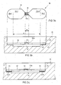
- FIG. 2 a shows a partial area of the lower link 15 with an eye 26 and the force sensor 25 in a greatly enlarged representation relative to FIG. 1.
- the eye 26 is the eye of the lower link 15 which is part of the swivel joint 17.
- the force sensor 25 is arranged in the vicinity of the machine-side eye 26 of the lower link 15.
- FIG. 2b shows a section along the line A - B.
- the force sensor 25 consists essentially of a strain gauge element 28, which is held in a depression 30 of the lower link 15 is. Details of the strain gauge 28 are shown in FIGS. 3a and 3b.
- FIG. 3a shows a top view of the strain-measuring element 28 in a simplified representation
- FIG. 3b shows a longitudinal view of the strain-measuring element 28 in the installation region shown in FIG. 2b.
- the strain gauge element 28 comprises a strip-shaped carrier element 32 and a strain gage 33 serving as a displacement sensor.
- the carrier element 32 has two end regions 32e1 and 32e2 in its longitudinal direction, a middle region 32m and intermediate regions 32l1 and 32l2 lying between them. The distance between the end regions 32e1 and 32e2 is designated by a.
- the central region 32m is made narrower than the end regions 32e1 and 32e2 and also narrower than the transition regions 32ü1 and 32ü2.
- the strain gauge 33 is fixedly connected to the support member 32 in the central region 32 m, z. B. by an adhesive bond.
- the strain gauge 33 is oriented to measure the elongation of the center region 32m in the longitudinal direction of the support member 32.
- the support member 32 of the Dehnungsmesselements 28 is held at the bottom provided with the reference numeral 40 of the recess 30.
- the end regions 32e1 and 32e2 of the support element 32 are fastened to the bottom of the depression via an adhesive bond.
- both the transition areas 32 ⁇ 1 and 32ü2 and the central area 32m are not connected to the floor 40.
- the depression 30 can be provided with an additional recess 41, which is formed in such a way that the carrier element 32 rests on the bottom 40 of the depression 30 only in the end regions 32e1 and 32e2.
- the support member 32 is thus movable between the end portions 32e1 and 32e2 relative to the lower link 15 when subjected to a longitudinal force.
- the depression 30 is formed such that the strain gauge element 28 lies in the neutral fiber 45 of the lower link 15, which is common with regard to the two bending directions.
- a bending stress of the lower link 15 has no influence on the output signal of the displacement sensor 33.
- the carrier element 32 Since the carrier element 32 is narrower in its middle region 32m than in the remaining regions, it lasts unevenly over its length when subjected to a tensile force acting in the longitudinal direction. At a constant thickness of the support member 32, the elongation of the width of the support member 32 is dependent, wherein in narrow areas, a greater elongation of the support member 32 takes place. This effect makes use of the invention.
- the width of the Rauchelemerits 32 is chosen so that at a force application, a lengthening practically only in the central region 32m takes place where the strain gauge 33 is arranged, and that in the remaining areas, the elongation is negligibly small.
- the center region 32m and with it also the strain gage 33 likewise increase by the value ⁇ a.
- the strain gauge 33 is thus more elongated than would be the case with a directly attached to the lower link 15 strain gauges. Denoting the length of the central region 32m with "d", the output signal of the strain gauge 33 increases by the factor a / d compared to the case in which the strain gauge 33 is attached directly to the lower link 15.
- the end portions 32e1 and 32e2 may be additionally provided with teeth 35 and 36, respectively, as shown in Fig. 3c.
- the toothing is a serration.
- the teeth 35 and 36 engage in correspondingly formed counter teeth 40t1 and 40t2 of the bottom 40. It should be enough clearance between the opposing teeth to ensure a tension-free attachment of the support member 32.
- the electrical connection of the strain gauge 33 via a plug 48 via a plug 48.
- the plug 48 is fixed with six screws 49 to the lower link 15.
- the flange portion 48a of the plug 48 forms a cover so that the plug 48 completely covers the recess 30.
- a seal enclosing the recess 30 can additionally be arranged between the plug 48 and the lower link 15 if required.
- a circuit board 51 is held at the projecting into the recess 30 parts of the connecting pins 50 of the plug 48.
- the connecting pins 50 simultaneously serve as an electrical connection between the plug 48 and the printed circuit board 51.
- the strain gauge 33 is connected via connecting wires 53 connected to the circuit board 51.
- the signal of the strain gauge 33 is usually only a few mV.
- the measuring amplifier is therefore arranged as close as possible to the strain gauge in order to reduce the influence of transmission errors and interference signals. At the output of the measuring amplifier you get a robust, car-friendly signal with a signal voltage between 0V and 10V, the unloaded state is signaled by a voltage of 5V.
- the carrier element 32 is connected at its outer end portions 32e1 and 32e2 by frictional engagement with the bottom 40 of the recess 30.
- a clamp is provided, which presses the end portions 32e1 and 32e2 to the bottom 40 of the recess 30.
- the contact surfaces are roughened to achieve a stronger frictional engagement.
- the recess 30 is covered by a cover 70 mounted on it.
- the cover 70 is screwed by screws 49 to the lower link 15.
- Spring packs 71 are clamped between the cover 70 and the carrier element 32 and press the end sections 32e1, 32e2 (see FIGS. 3a, 3b) of the carrier element 32 against the bottom 40.
- the contact pressure is chosen so that the frictional engagement generated thereby reliably transmits the expansion forces that are necessary for the elongation of the support member 32. Since the carrier element 32, in particular the central region 32m, has only a small cross section, the expansion forces required for its elongation are very small.
- FIG 4b Another variant of the clamp attachment is shown in Figure 4b.
- a cover 74 which is bolted to the lower link 15, and the support member 32 pins 75 are clamped.
- the pins 75 By the pins 75, the end portions 32e1, 32e2 of the support member 32 are pressed against the bottom 40 of the recess 30.
- a recess 41 ensures that only the end sections 32e1, 32e2 of the carrier element 32 are connected to the lower link 15.
- the clamping force on the pins 75 is applied by elastic deformation of the lid 74.
- the attachment of the lid 74 and the clamping of the pins 75 is shown in Figures 5a, 5b and 5c.
- Figures 5a, 5b and 5c show a cross section through the lower link 15 in the region of opposing screws 49. Further, the lid 74, holes 74a mounted therein, the recess 30, the support member 32 and the pins 75 are shown.
- the pins 75 have in relation to the depth of the recess 30 between the upper edge and the support member an excess length, ie they are slightly out of the recess 30.
- the pins 75 are placed over the end portions 32e1, 32e2 of the support member 32.
- the lid 74 is opposite with its holes 74a corresponding threaded holes 15 a arranged in the lower link 15.
- the lid 74 plastically deforms while maintaining a residual elasticity, as shown in Figure 5b. After removal of the screws 49, the lid 74 remains plastically deformed, as shown in Figure 5c.
- the residual elasticity present causes the clamping force on the pins 75.
- the lid 74 is made of a thin metal sheet. Due to the thickness of the metal sheet, the clamping force can be determined. Due to the plastic deformability of the lid, this clamp fastening variant permits large tolerances in the manufacture of the depression 30, so that the depression 30 or a lower link 15 which has such a depression 30 can be produced cost-effectively. In addition, also different material thicknesses of the carrier element can be compensated.
- the described clamps achieved a simple and reliable attachment of the support member 32 at the bottom 40. External mechanical stresses, as they may occur when welding or screwing the support member 32 to the bottom 40, do not occur. Thus, the strain gauge 28 is ready for use immediately after installation, without an adjustment of external mechanical stresses is performed.
- easily overload protection of the support member 32 and mounted thereon strain gauges 33 can be achieved by the contact pressure is chosen so that the frictional engagement transmits at most the maximum allowable tensile force.
- the strain gauge 28 the measuring amplifier and the fastening device can be provided as a pre-mounted strain gauge.
- FIG. 6 shows such a preassembled strain gauge sensor 80.
- the strain gauge sensor 80 is formed so as to be easily insertable into a recess 30 attached to the lower link 15.
- the dimensions of the strain gauge 80 are selected along with the depth of the recess so that the strain measurement is carried out in the neutral fiber of the lower link 15.
- On the cover 84 which has for screwing with the lower link 15 holes 84a, sets an elastic potting compound 76 at. This encloses the region of the strain gauge sensor 80 between the cover 84 and the carrier element 32. Furthermore, the central region 32m of the carrier element 32 is also enclosed by the potting compound in order to protect strain gauges 33 arranged thereon.
- the end portions 32e1, 32e2 of the support member 32 are not covered by the potting compound 76, so that a reliable frictional engagement between the end portions 32e1, 32e2 and the bottom 40 of the recess 30 is achieved.
- the area enclosed by the potting compound 76 also contains pins 75 or spring packs 71 which are arranged between the end sections 32e1, 32e2 and the cover 84, and the measuring amplifier for amplifying the signals of the strain gauge 33.
- a cable 82 is guided through the cover 84 in that the power supply of the measuring amplifier and the output signals leads.
- the strain gauge 80 By inserting the strain gauge 80 in the recess 30 and screwing the lid 84 with the lower link 15, the clamping attachment described with reference to Figures 4a or 4b is achieved. By wrapping with the potting compound 76, the individual elements of the strain gauge 80 are held in position to each other and are also protected from weather and dirt. Thus, the strain gauge 80 is ready for use immediately after insertion and screwing.
- the strain gauge sensor 80 may also be attached to the lower link 15 by gluing. However, it is important to ensure that only the end portions 32e1 and 32e2 of the support member 32 are bonded to the bottom 40 of the recess 30.
- the cover 84 can still be glued to the lower link outer surface.
- the strain gauge 28 can be further improved in resolution.
- Figure 7a and 7b the already described support member 32 is shown, on which now a plurality of strain gauges 90, 91, 92, 93 are arranged.
- the strain gauges 90 and 91 are connected to the central region 32m of the support member 32.
- the strain gauge 90 is disposed at the top and the strain gauge 91 at the bottom of the support member 32.
- the strain gauges 90, 91 are aligned to measure the elongation of the central region 32m in the longitudinal direction of the support member 32.
- the strain gauges 92 and 93 are arranged on the upper left and right of the central region 32 m on the upper side and aligned perpendicular to the strain gauges 90 and 91.
- strain gauges 90, 91, 92, 93 are connected in full-bridge connection. At the connection points B + and B- the supply voltage is supplied. At the terminals b1 and b2, an output signal for the measuring amplifier is removed. Strain gauges 90 and 91 are diagonally opposite each other in the full bridge circuit so that a change in length of midregion 32m results in a larger signal than would be the case using a single strain gauge.
- the strain gauges 92 and 93 which are arranged perpendicular to the direction of elongation, serve as reference resistors. As a result, the configuration of 4 strain gauges shown in FIGS. 7a, 7b and 7c is largely temperature-compensated.
- the strain gauge element may consist of a serving as a support member 32 ceramic board, which is provided with one or more, serving as a position sensor thin-film strain gauges.
- a magneto-elastic encoder can be used.
- the force measuring device consists of a force-transmitting component on which a strain gauge is held, which consists of a support member and a displacement sensor. Carrier element and displacement sensor are firmly connected to one another in a middle region of the carrier element. With the force-transmitting component only the end portions of the support element are connected. As explained below, the force measuring device according to the invention can be transferred to various other areas of application.
- Figures 8a and 8b show a force measuring device 59 according to the invention, in which the force-transmitting component is designed as a tab 60.
- the tab 60 is provided at its longitudinal ends with one eye 61 and 62, respectively.
- the eyes 61 and 62 serve to receive connecting elements for universal use of the force measuring device, for. B. also in the power flow of lifting equipment.
- the further construction of the force-measuring device 59 is consistent with the structure of the force-measuring device described in FIGS. 2a and 2b and will therefore not be described again in detail here.
- the further embodiments described above, in particular the use of a clamping attachment for the carrier element 32, or the integration of the strain gauge element 28 in a preassembled strain sensor 80 can be transferred to the trained as a tab 60 force measuring device 59 with little or no modification.
Landscapes
- Chemical & Material Sciences (AREA)
- Physics & Mathematics (AREA)
- General Physics & Mathematics (AREA)
- Life Sciences & Earth Sciences (AREA)
- Engineering & Computer Science (AREA)
- Analytical Chemistry (AREA)
- Mechanical Engineering (AREA)
- Soil Sciences (AREA)
- Environmental Sciences (AREA)
- Combustion & Propulsion (AREA)
- Force Measurement Appropriate To Specific Purposes (AREA)
- Measurement Of Force In General (AREA)
Abstract
Description
Die Erfindung betrifft eine Kraftmessvorrichtung in Form eines kraftübertragenden Bauteils mit einem an dem Bauteil gehaltenen Dehnungsmesselement, das die kraftabhängige Dehnung des Bauteils in ein elektrisches Signal umformt. Des Weiteren betrifft die Erfindung ein Dehnüngsmesselement, dass die kraftabhängige Dehnung eines Bauteils erfasst.The invention relates to a force measuring device in the form of a force-transmitting component with an expansion element held on the component, which converts the force-dependent expansion of the component into an electrical signal. Furthermore, the invention relates to a Dehnüngsmesselement that detects the force-dependent strain of a component.
Ein Zugkraftaufnehmer ist aus der DE 41 03 765 A1 bekannt. Eine Lasche, die an ihren beiden Längsenden je ein Auge besitzt, ist in dem Bereich zwischen den Augen von zwei Seiten mit einer zylinderförmigen Vertiefung versehen. Auf den Boden der Vertiefungen ist ein als Dehnungsmesselement dienender Dehnungsmessstreifen geklebt. Die Lasche ist beispielsweise in den Kraftfluss eines eine Last transportierenden Krans eingefügt. Dabei verformt sich die Lasche entsprechend der Kraft, mit der sie beaufschlagt ist. Die Verformung der Lasche verformt in gleicher Weise den auf den Boden der Vertiefung geklebten Dehnungsmessstreifen. Dabei ändert sich das elektrische Ausgangssignal des Dehnungsmessstreifens entsprechend der Verformung des Dehnungsmessstreifens.A Zugkraftaufnehmer is known from DE 41 03 765 A1. A tab, which has one eye at each of its two longitudinal ends, is provided in the area between the eyes from two sides with a cylindrical depression. On the bottom of the wells serving as a strain gauge strain gauge is glued. The tab is inserted, for example, in the power flow of a load-carrying crane. In this case, the tab deforms according to the force with which it is acted upon. The deformation of the tab deforms in the same way the bonded to the bottom of the recess strain gauges. In this case, the electrical output signal of the strain gauge changes according to the deformation of the strain gauge.
Der bekannte Kraftaufnehmer ist zur Messung von Kräften im groben Kran- und Schiffsbetrieb bis zu einer Größenordnung von einigen hundert Tonnen vorgesehen. Sollen demgegenüber kleinere Kräfte gemessen werden, ist die von der Belastung abhängige Verformung der Lasche zu klein, um ein verwertbares elektrisches Ausgangssignal des Dehnungsmessstreifens zu erhalten.The known force transducer is provided for measuring forces in rough crane and ship operation up to a magnitude of a few hundred tons. If, on the other hand, smaller forces are to be measured, the load-dependent deformation of the tab is too small to obtain a usable electrical output signal of the strain gauge.
Der Erfindung liegt die Aufgabe zugrunde, bei einer Kraftmessvorrichtung der eingangs genannten Art die Auflösung zu verbessern, also insbesondere bei gleicher Verformung des kraftübertragenden Bauteils ein größeres elektrisches Ausgangssignal zu erhalten.The invention has for its object to improve the resolution in a force measuring device of the type mentioned, so in particular to obtain a larger electrical output signal with the same deformation of the force-transmitting component.
Diese Aufgabe wird erfindungsgemäß durch eine Kraftmessvorrichtung mit den Merkmalen des Anspruchs 1 sowie ein Dehnungsmesselement mit den Merkmalen des Anspruchs 21 gelöst.This object is achieved by a force measuring device with the features of claim 1 and a strain gauge with the features of claim 21.
Durch den zweiteiligen Aufbau des eingesetzten Dehnungsmesselements aus einem Trägerelement und einem Weggeber, und durch die besondere Form des Trägerelements, das die Dehnung auf einer großen Länge des Bauteils erfasst und auf einen kleinen querschnittsreduzierten Abschnitt projiziert, auf dem der Weggeber angeordnet ist, erfolgt eine Verstärkung der kraftabhängigen Verformung des kraftübertragenden Bauteils. Durch die so erzielte Vergrößerung der Verformung des Trägerelements im Bereich des Weggebers ergibt sich eine entsprechende Erhöhung des elektrischen Ausgangssignals des Weggebers. Somit kann an einem Bauteil, das z.B. zur Aufnahme einer mechanischen Biegebelastung entsprechend kräftig ausgebildet ist, eine der Biegebelastung unabhängig überlagerte Zugbelastung zuverlässig gemessen werden.Due to the two-part construction of the strain gauge used from a support member and a displacement sensor, and by the particular shape of the support member, which detects the elongation on a large length of the component and projected onto a small cross-section reduced portion on which the displacement sensor is arranged, there is a gain the force-dependent deformation of the force-transmitting component. The thus achieved increase in the deformation of the carrier element in the region of the displacement sensor results in a corresponding increase in the electrical output signal of the displacement sensor. Thus, on a component, e.g. is designed to be strong enough to accommodate a mechanical bending load, a bending load independently superimposed tensile load can be reliably measured.
Vorteilhafte Weiterbildungen der Erfindung sind in den Unteransprüchen gekennzeichnet.Advantageous developments of the invention are characterized in the subclaims.
Eine Ausnehmung im Bauteil, über dem der Dehnungsabschnitt sowie die daran angrenzenden Abschnitte des Trägerelements angeordnet sind, gewährleistet im Abschnitt zwischen den Befestigungsabschnitten die freie Beweglichkeit des Trägerelements gegenüber dem Bauteil. Dadurch wird die unterschiedliche Längung einzelner Abschnitte des Trägerelements zuverlässig ermöglicht. Die Anordnung des Dehnungsmesselements am Boden einer Vertiefung im Bauteil schützt dieses vor mechanischer Beschädigung. Ist die Vertiefung so gestaltet, dass das Dehnungsmesselements im Bereich der neutralen Faser des Bauteils liegt, so ist das Ausgangssignal des Weggebers unabhängig von einer Biegebeanspruchung des Bauteils. Eine einfache und zuverlässige Befestigung ergibt sich durch Verkleben der Befestigungsabschnitte des Trägerelements mit dem Bauteil. Eine Verzahnung der Befestigungsabschnitte des Trägerelements sowie eine entsprechend gegenüberliegende Verzahnung am Bauteil verbessern die Festigkeit der Verbindung.A recess in the component, over which the expansion section and the adjoining sections of the carrier element are arranged, ensures the free movement of the carrier element relative to the component in the section between the attachment sections. As a result, the different elongation of individual sections of the carrier element is made possible reliably. The arrangement of the strain gauge at the bottom of a recess in the component protects it from mechanical damage. If the recess is designed so that the strain gauge element lies in the region of the neutral fiber of the component, the output signal of the displacement sensor is independent of a bending stress of the component. A simple and reliable attachment results from bonding the mounting portions of the support member with the component. A toothing of the attachment portions of the support member and a corresponding opposite teeth on the component improve the strength of the connection.
In einer besonders bevorzugten Ausgestaltung erfolgt die Befestigung des Trägerelements am Bauteil über eine Klemmverbindung. Durch die Klemmverbindung kommt ein Reibschluss zwischen Trägerelement und Bauteil zustande. Somit wirken keine durch die Befestigung hervorgerufenen Fremdspannungen auf das Dehnungsmesselement ein, so dass das Dehnungsmesselement die Dehnung ohne Abgleich präzise und zuverlässig misst. Außerdem wird durch das Vorsehen einer Klemmverbindung ein Überlastschutz des Dehnungsmesselements erzielt. Die Klemmverbindung ist in bevorzugter Weise als Deckel, der am Bauteil gehalten wird und die Vertiefung abdeckt, und zwischen dem Deckel und dem Trägerelement eingespannten Stiften ausgebildet. Dadurch wird eine einfache Klemmbefestigung erzielt, die in der Lage ist auch größere Fertigungstoleranzen beim Fertigen der Vertiefung auszugleichen. Dazu ist vorzugsweise die Länge der Stifte so bemessen, dass sie über den Rand der Vertiefung herausstehen und der Deckel ist unter Beibehaltung einer Restelastizität plastisch verformbar.In a particularly preferred embodiment, the attachment of the carrier element takes place on the component via a clamping connection. Due to the clamping connection, a frictional connection between the carrier element and the component is achieved. Thus, no external stresses caused by the attachment act on the strain gauge, so that the strain gauge measures the strain accurately and reliably without alignment. In addition, an overload protection of the strain gauge is achieved by providing a clamp connection. The clamp connection is preferably formed as a lid, which is held on the component and covers the recess, and formed between the lid and the support member clamped pins. As a result, a simple clamping attachment is achieved, which is able to compensate for larger manufacturing tolerances in the manufacture of the recess. For this purpose, preferably, the length of the pins is dimensioned so that they protrude beyond the edge of the recess and the lid is plastically deformable while maintaining a residual elasticity.
Vorzugsweise ist das Dehnungsmesselement als vormontierte Baueinheit zum Einsetzen in eine Vertiefung des Bauteils ausgebildet und weist zusätzlich zum Trägerelement und dem Weggeber wenigsten einen Deckel zum Abdecken der Vertiefung, eine elektronische Verstärkerschaltung, um ein elektrisches Signal des Weggebers zu verstärken, und eine zwischen dem Deckel und dem Trägerelement vorgesehene, das Dehnungsmesselement teilweise umschließende elastische Vergussmasse auf. Dabei ist die einem Boden der Vertiefung zugewandte Seite der Befestigungsabschnitte jeweils von der Vergussmasse nicht bedeckt. Eine solche Baueinheit lässt sich mit geringen Installatiorisaufwand in bestehende Bauteile integrieren bzw. erleichtert die Fertigung von Kraftaufnehmern. Durch die Integration einer Verstärkerschaltung in der vormontierten Baueinheit lassen sich Übertragungsstörungen des Weggebersignals vermeiden. Zudem stellt die Verstärkerschaltung ein robustes, KFZ-gerechtes Messsignal bereit. Die Vergussmasse schützt den Weggeber und die Verstärkerschaltung vor Beschädigung durch Witterung oder eindringenden Schmutz.Preferably, the strain gauge is designed as a preassembled unit for insertion into a recess of the component and has in addition to the carrier element and the Weggeber least a cover for covering the recess, an electronic amplifier circuit to amplify an electrical signal of the encoder, and a between the lid and provided on the support member, the strain gauge partially enclosing elastic potting compound. In this case, the bottom of the recess facing side of the mounting portions is not covered in each case by the potting compound. Such a unit can be integrated with low Installatiorisaufwand in existing components or facilitates the production of force transducers. By integrating an amplifier circuit in the preassembled unit, transmission disturbances of the position encoder signal can be avoided. In addition, the amplifier circuit provides a robust, vehicle-friendly measurement signal. The potting compound protects the encoder and the amplifier circuit from damage due to weathering or penetrating dirt.
Der Weggeber ist in vorteilhafter Weise als Dehnungsmessstreifen oder als magneto-elastischer Geber ausgebildet. In vorteilhafter Weise ist das Trägerelement als Keramikplatine ausgebildet und mit einem oder mehreren Dünnschicht-Dehnungsmessstreifen versehen.The displacement sensor is advantageously designed as a strain gauge or as a magneto-elastic encoder. Advantageously, the carrier element is designed as a ceramic board and provided with one or more thin-film strain gauges.
Um die Kraft zu messen, mit der ein an einer landwirtschaftlichen Maschine gehaltenes Anbaugerät an ihr angreift, wird das Dehnungsmesselement in einer Vertiefung eines Unterlenkers eines Hubwerks angeordnet, über den das Anbaugerät an der landwirtschaftlichen Maschine gehalten ist. Dabei ist die Vertiefung für die Aufnahme des Dehnungsmesselements in vorteilhafter Weise in der Nähe des maschinenseitigen Auges des Unterlenkers angeordnet. Das Bauteil für die Aufnahme des Dehnungsmesselements kann auch als Lasche ausgebildet sein, die an ihren Längsenden mit jeweils einem Auge für die Aufnahme von Verbindungselementen, wie z. B. Bolzen, versehen ist. Diese Ausgestaltung erlaubt einen universellen Einsatz der erfindungsgemäßen Kraftmessvorrichtung, z. B. auch im Kraftfluss von Hebezeugen.In order to measure the force with which a mounted on an agricultural machine attachment acts on her, the strain gauge is disposed in a recess of a lower link of a hoist, via which the attachment is held on the agricultural machine. In this case, the recess for receiving the strain gauge is arranged in an advantageous manner in the vicinity of the machine-side eye of the lower link. The component for receiving the Dehnungsmesselements can also be designed as a tab, which at their longitudinal ends, each with an eye for receiving fasteners such. B. bolts provided. This embodiment allows a universal use of the force measuring device according to the invention, for. B. also in the power flow of lifting equipment.
Die Erfindung wird im Folgenden mit ihren weiteren Einzelheiten anhand von in den Zeichnungen dargestellten Ausführungsbeispielen näher erläutert. Es zeigen
- Figur 1
- einen Ackerschlepper mit einem an seiner Rückseite gehaltenen Hubwerk für einen Pflug,
- Figur 2a
- die Seitenansicht eines Abschnitts eines Unterlenkers, über den sich das Hubwerk an dem Ackerschlepper abstützt,
- Figur 2b
- einen Schnitt A-B durch den in der Figur 2a dargestellten Bereich des Unterlenkers,
- Figur 3a
- eine Draufsicht auf ein erfindungsgemäß ausgebildetes Dehnungsmesselement,
- Figur 3b
- ein Längsschnitt durch den Einbaubereich im Unterlenker mit Seitenansicht des in Figur 3a dargestellten Dehnungsmesselements und,
- Figur 3c
- ein Längsschnitt des Einbaubereichs des Dehnungsmesselements, wobei die Befestigungsabschnitte mit einer Verzahnung versehen sind,
- Figur 4a
- ein Längsschnitt des Einbaubereichs des Dehnungsmesselements, wobei die Befestigung des Trägerelements über Federpakete erfolgt,
- Figur 4b
- ein Längsschnitt des Einbaubereichs des Dehnungsmesselements, wobei die Befestigung des Trägerelements über eingespannte Stifte erfolgt,
- Figur 5a
- ein Querschnitt durch den Einbaubereich des Dehnungsmesselements hinsichtlich der in Figur 4b dargestellten Befestigungsvariante im Zustand vor der Montage des Deckels,
- Figur 5b
- der in Figur 5a dargestellte Querschnitt nach Montage des Deckels durch Schraubverbindungen,
- Figur 5c
- der in Figur 5b dargestellte Querschnitt nach Lösen der Schraubverbindungen,
- Figur 6
- ein Dehnungssensor in Form eines vormontierten, teilweise vergossenen Bauteils,
- Figur 7a
- ein mit mehreren Dehnungsmessstreifen bestücktes Trägerelement in Draufsicht,
- Figur 7b
- das in Figur 7a dargestellte Trägerelement in Seitenansicht,
- Figur 7c
- die elektrische Verschaltung der auf dem in Figur 7a und 7b dargestellten Dehnungsmessstreifen,
- Figur 8a
- die Seitenansicht eines als Lasche ausgebildeten Kraftaufnehmers und
- Figur 8b
- einen Schnitt durch die in der Figur 4a dargestellte Lasche.
- FIG. 1
- an agricultural tractor with a lifting device for a plow held on its back,
- FIG. 2a
- the side view of a portion of a lower link, over which the hoist is supported on the tractor,
- FIG. 2b
- a section AB through the region of the lower link shown in Figure 2a,
- FIG. 3a
- a top view of an inventively formed strain gauge,
- FIG. 3b
- a longitudinal section through the installation area in the lower link with a side view of the strain gauge shown in Figure 3a and,
- Figure 3c
- a longitudinal section of the installation region of the strain gauge, wherein the mounting portions are provided with a toothing,
- FIG. 4a
- a longitudinal section of the installation area of the strain gauge, wherein the attachment of the support element via spring assemblies,
- FIG. 4b
- a longitudinal section of the installation area of the strain gauge, wherein the attachment of the support member via clamped pins,
- FIG. 5a
- a cross section through the installation area of the expansion element with respect to the mounting variant shown in Figure 4b in the state prior to installation of the lid,
- FIG. 5b
- the cross section shown in Figure 5a after mounting the lid by screw,
- FIG. 5c
- the cross section shown in Figure 5b after loosening the screw,
- FIG. 6
- a strain sensor in the form of a pre-assembled, partially molded component,
- Figure 7a
- a carrier element equipped with a plurality of strain gauges in plan view,
- FIG. 7b
- the support element shown in Figure 7a in side view,
- FIG. 7c
- the electrical connection of the strain gauges shown in FIGS. 7a and 7b,
- FIG. 8a
- the side view of a trained as a tab force transducer and
- FIG. 8b
- a section through the tab shown in Figure 4a.
Die Figur 1 zeigt in schematischer Darstellung einen Ackerschlepper 10, an dessen Rückseite ein Hubwerk 11 mit einem Pflug 12 gehalten ist. Der Ackerschlepper 10 dient hier als Beispiel für eine landwirtschaftliche Maschine. Das Hubwerk 11 stützt sich über verschiedene Lenker an der Rückseite des Ackerschleppers 10 ab. Von diesen Lenkern sind in der Figur 1 ein Unterlenker 15 und ein Oberlenker 16 dargestellt. Der Unterlenker 15 ist über ein erstes Drehgelenk 17 an dem Ackerschlepper 10 gehalten. Über ein zweites Drehgelenk 18 ist ein Anbaugerät wie der Pflug 12 an dem Unterlenker 15 gehalten. Der Unterlenker 15 ist an seinen Längsenden mit je einem Auge versehen, das jeweils einen Teil der Drehgelenke 17 bzw. 18 bildet. Ein derartiges Auge ist in den Figuren 2a und 2b dargestellt. Ein hydraulischer Zylinder 20 hebt und senkt das Hubwerk 11 über ein aus einem Hebel 22 und einer Stange 23 gebildetes Gestänge. An dem Unterlenker 15 ist in der Nähe des Drehgelenks 17 ein Kraftsensor 25 angeordnet. Einzelheiten des Kraftsensors 25 sind im Folgenden anhand der Figuren 2a bis 7c beschrieben.1 shows a schematic representation of a
Die Figur 2a zeigt in gegenüber der Figur 1 stark vergrößerter Darstellung einen Teilbereich des Unterlenkers 15 mit einem Auge 26 und dem Kraftsensor 25. Bei dem Auge 26 handelt es sich um das Auge des Unterlenkers 15, das Bestandteil des Drehgelenks 17 ist. Der Kraftsensor 25 ist in der Nähe des maschinenseitigen Auges 26 des Unterlenkers 15, angeordnet. Die Figur 2b zeigt einen Schnitt entlang der Linie A - B. Der Kraftsensor 25 besteht im Wesentlichen aus einem Dehnungsmesselement 28, das in einer Vertiefung 30 des Unterlenkers 15 gehalten ist. In den Figuren 3a und 3b sind Einzelheiten des Dehnungsmesselements 28 dargestellt.FIG. 2 a shows a partial area of the
Die Figur 3a zeigt eine Draufsicht auf das Dehnungsmesselement 28 in vereinfachter Darstellung, während die Figur 3b eine Längsansicht des Dehnungsmesselements 28 in dem in Fig. 2b dargestellten Einbaubereich zeigt. Das Dehnungsmesselement 28 besteht aus einem streifenförmigen Trägerelement 32 und einem als Weggeber dienenden Dehnungsmessstreifen 33. Das Trägerelement 32 weist in seiner Längsrichtung zwei Endbereiche 32e1 und 32e2, einen Mittelbereich 32m sowie zwischen diesen liegende Übergangsbereiche 32ü1 und 32ü2 auf. Der Abstand zwischen den Endbereichen 32e1 und 32e2 ist mit a bezeichnet. Der Mittelbereich 32m ist schmäler ausgebildet als die Endbereiche 32e1 und 32e2 und auch schmäler als die Übergangsbereiche 32ü1 und 32ü2. Dies bedeutet, dass der Querschnitt des Trägerelements 32 im Mittelbereich 32m kleiner als in den übrigen Bereichen des Trägerelements 32 ist. Der Dehnungsmessstreifen 33 ist mit dem Trägerelement 32 in dessen Mittelbereich 32m fest verbunden, z. B. durch eine Klebverbindung. Der Dehnungsmessstreifen 33 ist so ausgerichtet, dass er die Dehnung des Mittelbereichs 32m in der Längsrichtung des Trägerelements 32 misst.FIG. 3a shows a top view of the strain-measuring
Wie in der Figur 2b bzw. 3b dargestellt, ist das Trägerelement 32 des Dehnungsmesselements 28 an dem mit dem Bezugszeichen 40 versehenen Boden der Vertiefung 30 gehalten. Dabei sind nur die Endbereiche 32e1 und 32e2 des Trägerelements 32 am Boden der Vertiefung über eine Klebverbindung befestigt. Sowohl die Übergangsbereiche 32ü1 und 32ü2 als auch der Mittelbereich 32m sind dagegen nicht mit dem Boden 40 verbunden. Die Vertiefung 30 kann hierfür mit einer zusätzlichen Ausnehmung 41 versehen sein, die so ausgebildet ist, dass das Trägerelement 32 nur in den Endbereichen 32e1 und 32e2 auf dem Boden 40 der Vertiefung 30 aufliegt. Das Trägerelement 32 ist somit zwischen den Endbereichen 32e1 und 32e2 relativ zu dem Unterlenker 15 beweglich, wenn dieser mit einer in Längsrichtung wirkenden Kraft beaufschlagt wird.As shown in Figure 2b and 3b, the
Auf den Unterlenker 15 wirkt zusätzlich zur Zug- oder Druckbelastung eine erhebliche Biegelast in vertikaler Richtung beim Halten bzw. Ausheben eines landwirtschaftlichen Anbaugeräts ein (siehe Figur 1). Zudem kann eine Biegebelastung quer zur Schlepprichtung auftreten. Um die Zugkraft unabhängig von solchen quer zur Unterlenkerlängsachse auftretenden Biegelasten zu messen, ist die Vertiefung 30 so ausgebildet, dass das Dehnungsmesselement 28 in der hinsichtlich der beiden Biegerichtungen gemeinsamen neutralen Faser 45 des Unterlenkers 15 liegt. Somit hat eine Biegebeanspruchung des Unterlenkers 15 keinen Einfluss auf das Ausgangssignal des Weggebers 33.On the
Da das Trägerelement 32 in seinem Mittelbereich 32m schmäler ist als in den restlichen Bereichen, längt es sich bei Beaufschlagung mit einer in Längsrichtung wirkenden Zugkraft ungleichmäßig über seine Länge. Bei konstanter Dicke des Trägerelements 32 ist die Längung von der Breite des Trägerelements 32 abhängig, wobei in schmalen Bereichen eine größere Längung des Trägerelements 32 erfolgt. Diesen Effekt nutzt die Erfindung aus. Die Breite des Trägerelemerits 32 wird so gewählt, dass bei einer Kraftbeaufschlagung eine Längung praktisch nur in dem Mittelbereich 32m erfolgt, wo der Dehnungsmessstreifen 33 angeordnet ist, und dass in den restlichen Bereichen die Längung vernachlässigbar klein ist. Vergrößert sich der Abstand a zwischen den Endbereichen 32e1 und 32e2 bei einer Kraftbeaufschlagung um den Wert Δa, so vergrößert sich der Mittelbereich 32m und mit diesem auch der Dehnungsmessstreifen 33 ebenfalls um den Wert Δa. Der Dehnungsmessstreifen 33 wird somit stärker gelängt, als dies bei einem direkt an dem Unterlenker 15 befestigten Dehnungsmessstreifen der Fall wäre. Bezeichnet man die Länge des Mittelbereichs 32m mit "d", so vergrößert sich das Ausgangssignal des Dehnungsmessstreifens 33 um den Faktor a/d gegenüber dem Fall, in dem der Dehnungsmessstreifen 33 direkt an dem Unterlenker 15 befestigt ist.Since the
Um die Festigkeit der Klebeverbindung der Endbereiche 32e1 und 32e2 mit dem Boden 40 der Vertiefung 30 zu erhöhen, können die Endbereiche 32e1 und 32e2 zusätzlich mit einer Verzahnung 35 bzw. 36 versehen sein, wie in Figur 3c dargestellt. Bei der Verzahnung handelt es sich um eine Kerbverzahnung. Dabei greifen die Verzahnungen 35 und 36 in entsprechend ausgebildete Gegenverzahnungen 40t1 und 40t2 des Bodens 40 ein. Dabei sollte zwischen den gegenüberliegenden Verzahnungen genügend Spiel bestehen um eine verspannungsfreie Befestigung des Trägerelements 32 zu gewährleisten.In order to increase the strength of the adhesive bond of the end portions 32e1 and 32e2 to the bottom 40 of the
Wie in Figur 2a und 2b dargestellt, erfolgt der elektrische Anschluss des Dehnungsmessstreifens 33 über einen Stecker 48. Der Stecker 48 ist mit sechs Schrauben 49 an dem Unterlenker 15 befestigt. Dabei bildet der Flanschbereich 48a des Steckers 48 einen Deckel, so dass der Stecker 48 die Vertiefung 30 vollständig abdeckt. Um die Vertiefung 30 noch besser gegen das Eindringen von Staub oder Feuchtigkeit abzudichten, kann bei Bedarf zusätzlich eine die Vertiefung 30 umschließende Dichtung zwischen dem Stecker 48 und dem Unterlenker 15 angeordnet werden. An den in die Vertiefung 30 ragenden Teilen der Anschlussstifte 50 des Steckers 48 ist eine Leiterplatte 51 gehalten. Die Anschlussstifte 50 dienen gleichzeitig als elektrische Verbindung zwischen dem Stecker 48 und der Leiterplatte 51. Die Leiterplatte 51 bildet zusammen mit den auf ihr angeordneten elektrischen Bauteilen 52 einen Messverstärker zum Auslesen und Verstärken des Signals des Dehnungsmessstreifens 33. Der Dehnungsmessstreifen 33 ist über Anschlussdrähte 53 mit der Leiterplatte 51 verbunden. Das Signal des Dehnungsmessstreifens 33 beträgt üblicherweise nur einige mV. Der Messverstärker ist daher möglichst nah am Dehnungsmessstreifen angeordnet, um den Einfluss von Übertragungsfehlern und Störsignalen zu vermindern. Am Ausgang des Messverstärkers erhält man ein robustes, KFZ-gerechtes Signal mit einer Signalspannung zwischen 0V und 10V, wobei der unbelastete Zustand durch eine Spannung von 5V signalisiert wird.As shown in Figure 2a and 2b, the electrical connection of the
Anhand der Figuren 4a, 4b, 5a, 5b und 5c werden nun alternative Befestigungsmöglichkeiten für das Dehnungsmesselement 28, insbesondere das Trägerelement 32 beschrieben. Bei diesen Befestigungsvarianten ist das Trägerelement 32 an seinen äußeren Endabschnitten 32e1 und 32e2 durch Reibschluss mit dem Boden 40 der Vertiefung 30 verbunden. Dazu ist eine Klemmbefestigung vorgesehen, die die Endabschnitte 32e1 und 32e2 an den Boden 40 der Vertiefung 30 anpresst. Gegebenenfalls sind die Kontaktflächen angeraut, um einen stärkeren Reibschluss zu erzielen.With reference to FIGS. 4a, 4b, 5a, 5b and 5c, alternative attachment possibilities for the
Wie in Figur 4a dargestellt, wird die Vertiefung 30 durch einen auf ihr befestigten Deckel 70 abgedeckt. Der Deckel 70 ist über Schrauben 49 mit dem Unterlenker 15 verschraubt. Zwischen dem Deckel 70 und dem Trägerelement 32 sind Federpakete 71 eingespannt, welche die Endabschnitte 32e1, 32e2 (siehe Figur 3a, 3b) des Trägerelements 32 an dem Boden 40 anpressen. Die Anpresskraft ist dabei so gewählt, dass der dadurch erzeugte Reibschluss die Dehnungskräfte, die für die Längung des Trägerelements 32 notwendig sind, zuverlässig überträgt. Da das Trägerelement 32, insbesondere der Mittelbereich 32m, nur einen geringen Querschnitt hat, sind die für seine Längung erforderlichen Dehnungskräfte sehr gering.As shown in Figure 4a, the
Eine weitere Variante der Klemmbefestigung ist in Figur 4b dargestellt. Zwischen einem Deckel 74, der mit dem Unterlenker 15 verschraubt ist, und dem Trägerelement 32 sind Stifte 75 eingespannt. Durch die Stifte 75 werden die Endabschnitte 32e1, 32e2 des Trägerelements 32 an den Boden 40 der Vertiefung 30 angepresst. Eine Aussparung 41 gewährleistet, dass nur die Endabschnitte 32e1, 32e2 des Trägerelements 32 mit dem Unterlenker 15 verbunden sind. Die Einspannkraft auf die Stifte 75 wird durch eine elastische Verformung des Deckels 74 aufgebracht. Die Befestigung des Deckels 74 und das Einspannen der Stifte 75 ist in den Figuren 5a, 5b und 5c dargestellt.Another variant of the clamp attachment is shown in Figure 4b. Between a
Die Figuren 5a, 5b und 5c zeigen einen Querschnitt durch den Unterlenker 15 im Bereich gegenüberliegender Schrauben 49. Weiter sind der Deckel 74, darin angebrachte Bohrungen 74a, die Vertiefung 30, das Trägerelement 32 sowie die Stifte 75 dargestellt. Die Stifte 75 haben in Bezug auf die Tiefe der Vertiefung 30 zwischen deren Oberkante und dem Trägerelement eine Überlänge, d.h. sie stehen etwas aus der Vertiefung 30 hervor. Zur Befestigung der Stifte 75 und des Deckels 74 werden die Stifte 75 über den Endabschnitten 32e1, 32e2 des Trägerelements 32 angeordnet. Der Deckel 74 wird mit seinen Bohrungen 74a gegenüber entsprechenden Gewindebohrungen 15a im Unterlenker 15 angeordnet. Bei Einsetzen und Anziehen der Schrauben 49 verformt sich der Deckel 74 unter Beibehaltung einer Restelastizität plastisch, wie in Figur 5b dargestellt. Nach Entfernen der Schrauben 49 bleibt der Deckel 74 plastisch verformt, wie in Figur 5c gezeigt. Die vorhandene Restselastizität bewirkt die Einspannkraft auf die Stifte 75. In geeigneter Weise ist der Deckel 74 aus einem dünnen Metallblech gefertigt. Durch die Stärke des Metallblechs lässt sich die Einspannkraft festlegen. Diese Klemmbefestigungsvariante erlaubt durch die plastische Verformbarkeit des Deckels große Toleranzen beim Fertigen der Vertiefung 30, so dass die Vertiefung 30 bzw. ein Unterlenker 15 der eine solche Vertiefung 30 aufweist kostengünstig herstellbar ist. Außerdem könneri auch unterschiedliche Materialstärken des Trägerelements ausgeglichen werden.Figures 5a, 5b and 5c show a cross section through the
Durch die beschriebenen Klemmbefestigungen erzielt man eine einfache und zuverlässige Befestigung des Trägerelements 32 am Boden 40. Mechanische Fremdspannungen, wie sie bei einem Verschweißen oder Verschrauben des Trägerelements 32 mit dem Boden 40 auftreten können, treten nicht auf. Somit ist das Dehnungsmesselement 28 sofort nach dem Einbau betriebsbereit, ohne dass ein Abgleich von mechanischen Fremdspannungen durchzuführen ist. Außerdem lässt sich bei einer Klemmbefestigung in einfacher Weise ein Überlastschutz des Trägerelements 32 und darauf angebrachter Dehnungsmessstreifen 33 erzielen, indem die Anpresskraft so gewählt wird, dass der Reibschluss höchstens die maximal zulässige Dehnkraft überträgt.The described clamps achieved a simple and reliable attachment of the
Um den Arbeitsaufwand für die Ausrüstung eines Unterlenkers mit dem erfindungsgemäßen Kraftsensor 25 gering zu halten, kann das Dehnungsmesselement 28, der Messverstärker und die Befestigungseinrichtung als vormontierter Dehnungsmesssensor bereitgestellt werden.In order to keep the workload for the equipment of a lower link with the
In Figur 6 ist ein solcher vormontierter Dehnungsmesssensor 80 dargestellt. Der Dehnungsmesssensor 80 ist so ausgebildet, dass er einfach in eine am Unterlenker 15 angebrachte Vertiefung 30 einsetzbar ist. Die Abmessungen des Dehnungsmesssensors 80 sind zusammen mit der Tiefe der Vertiefung so gewählt, dass die Dehnungsmessung in der neutralen Faser des Unterlenkers 15 erfolgt. An dem Deckel 84, der zur Verschraubung mit dem Unterlenker 15 Bohrungen 84a aufweist, setzt eine elastische Vergussmasse 76 an. Diese umschließt den Bereich des Dehnungsmesssensors 80 zwischen dem Deckel 84 und dem Trägerelement 32. Des Weiteren ist auch der Mittelbereich 32m des Trägerelements 32 von der Vergussmasse umschlossen, um darauf angeordnete Dehnungsmessstreifen 33 zu schützen. Die Endabschnitte 32e1, 32e2 des Trägerelements 32 sind von der Vergussmasse 76 nicht bedeckt, so dass ein zuverlässiger Reibschluss zwischen den Endabschnitten 32e1, 32e2 und dem Boden 40 der Vertiefung 30 erzielt wird. Der von der Vergussmasse 76 umschlossene Bereich enthält des Weiteren Stifte 75 oder Federpakete 71, die zwischen den Endabschnitten 32e1, 32e2 und dem Deckel 84 angeordnet sind, sowie den Messverstärker zum Verstärken der Signale des Dehnungsmessstreifens 33. Durch den Deckel 84 ist ein Kabel 82 geführt, dass die Spannungsversorgung des Messverstärkers und die Ausgangssignale führt.FIG. 6 shows such a preassembled
Durch Einsetzen des Dehnungsmesssensors 80 in die Vertiefung 30 und Verschrauben des Deckels 84 mit dem Unterlenker 15 wird die anhand der Figuren 4a oder 4b beschriebene Klemmbefestigung erzielt. Durch die Umhüllung mit der Vergussmasse 76 werden die einzelnen Elemente des Dehnungsmesssensors 80 in Position zueinander gehalten und sind zudem vor Witterung und Schmutz geschützt. Somit ist der Dehnungsmesssensors 80 sofort nach dem Einsetzen und Verschrauben betriebsbereit.By inserting the
Alternativ kann der Dehnungsmesssensor 80 auch durch Verkleben am Unterlenker 15 befestigt werden. Dann entfallen die Stifte 75 bzw. Federpakete 71. Es ist jedoch darauf zu achten, dass nur die Endabschnitte 32e1 und 32e2 des Trägerelements 32 mit dem Boden 40 der Vertiefung 30 verklebt werden. Gegebenenfalls kann noch der Deckel 84 mit der Unterlenkeraußenfläche verklebt werden.Alternatively, the
Durch Verwendung mehrerer Dehnungsmessstreifen lässt sich das Dehnungsmesselement 28 hinsichtlich der Auflösung weiter verbessern. In Figur 7a und 7b ist das schon beschriebene Trägerelement 32 dargestellt, auf dem nun mehrere Dehnungsmessstreifen 90, 91, 92, 93 angeordnet sind. Die Dehnungsmessstreifen 90 und 91 sind mit dem Mittelbereich 32m des Trägerelements 32 verbunden. Der Dehnungsmessstreifen 90 ist an der Oberseite und der Dehnungsmessstreifen 91 an der Unterseite des Trägerelements 32 angeordnet. Die Dehnungsmessstreifen 90, 91 sind so ausgerichtet, dass sie die Dehnung des Mittelbereichs 32m in Längsrichtung des Trägerelements 32 messen. Die Dehnungsmessstreifen 92 und 93 sind links bzw. rechts vom Mittelbereich 32m auf der Oberseite angeordnet und senkrecht zu den Dehnungsmessstreifen 90 und 91 ausgerichtet.By using multiple strain gauges, the
In der Figur 7c ist die elektrische Verschaltung der Dehnungsmessstreifen 90, 91, 92, 93 dargestellt. Die Dehnungsmessstreifen 90, 91, 92, 93 sind in Vollbrückenschaltung verbunden. An den Anschlussstellen B+ und B- wird die Versorgungsspannung zugeführt. An den Anschlüssen b1 und b2 wird ein Ausgangssignal für den Messverstärker abgenommen. Die Dehnungsmessstreifen 90 und 91 liegen in der Vollbrückenschaltung diagonal gegenüber, so dass eine Längenänderung des Mittelbereichs 32m zu einem größeren Signal führt als es bei der Verwendung eines einzelnen Dehnungsmessstreifens der Fall wäre. Die Dehnungsmessstreifen 92 und 93, die senkrecht zur Dehnungsrichtung angeordnet sind, dienen als Referenzwiderstände. Dadurch ist die in Figur 7a, 7b und 7c dargestellte Konfiguration von 4 Dehnungsmessstreifen weitgehend temperaturkompensiert.In the figure 7c, the electrical interconnection of the strain gauges 90, 91, 92, 93 is shown. The strain gauges 90, 91, 92, 93 are connected in full-bridge connection. At the connection points B + and B- the supply voltage is supplied. At the terminals b1 and b2, an output signal for the measuring amplifier is removed. Strain gauges 90 and 91 are diagonally opposite each other in the full bridge circuit so that a change in length of
Das Dehnungsmesselement kann aus einer als Trägerelement 32 dienenden Keramikplatine bestehen, die mit einem oder mehreren, als Weggeber dienenden Dünnschicht-Dehnungsmessstreifen versehen ist.The strain gauge element may consist of a serving as a
Als Weggeber kann anstelle der in den Ausführungsbeispielen eingesetzten Dehnungsmessstreifen auch ein magneto-elastischer Geber verwendet werden.As a displacement sensor, instead of the strain gauges used in the embodiments, a magneto-elastic encoder can be used.
Die vorliegende Erfindung ist nicht auf in Unterlenker einsetzbare Kraftsensoren beschränkt. Allgemein betrachtet besteht die erfindungsgemäße Kraftmessvorrichtung aus einem kraftübertragenden Bauteil, an dem ein Dehnungsmesselement gehalten ist, das aus einem Trägerelement und einem Weggeber besteht. Trägerelement und Weggeber sind in einem Mittelbereich des Trägerelements fest miteinander verbunden. Mit dem kraftübertragenden Bauteil sind nur die Endbereiche des Trägerelements verbunden. Wie im Folgenden ausgeführt, lässt sich die erfindungsgemäße Kraftmessvorrichtung auf verschiedene weitere Anwendungsbereiche übertragen.The present invention is not limited to insertable in lower link force sensors. Generally speaking, the force measuring device according to the invention consists of a force-transmitting component on which a strain gauge is held, which consists of a support member and a displacement sensor. Carrier element and displacement sensor are firmly connected to one another in a middle region of the carrier element. With the force-transmitting component only the end portions of the support element are connected. As explained below, the force measuring device according to the invention can be transferred to various other areas of application.
Die Figuren 8a und 8b zeigen eine erfindungsgemäßen Kraftmessvorrichtung 59, bei der das kraftübertragende Bauteil als Lasche 60 ausgebildet ist. Die Lasche 60 ist an ihren Längsenden mit je einem Auge 61 bzw. 62 versehen. Die Augen 61 und 62 dienen zur Aufnahme von Verbindungselementen für einen universellen Einsatz der Kraftmessvorrichtung, z. B. auch im Kraftfluss von Hebezeugen. Der weitere Aufbau der Kraftmessvorrichtung 59 stimmt mit dem Aufbau der in den Figuren 2a ünd.2b beschriebenen Kraftmessvorrichtung überein und wird deshalb hier nicht noch einmal im Einzelnen beschrieben. Die zuvor beschriebenen weiteren Ausgestaltungen, insbesondere die Verwendung einer Klemmbefestigung für das Trägerelement 32, oder die Integration des Dehnungsmesselements 28 in einen vormontierten Dehnungssensor 80 lassen sich auf die als Lasche 60 ausgebildete Kraftmessvorrichtung 59 ohne oder unter geringer Abwandlung übertragen.Figures 8a and 8b show a
Claims (22)
dadurch gekennzeichnet,
dass das Dehnungsmesselement (28) aus einem Trägerelement (32) und einem an diesem befestigten Weggeber (33) gebildet ist,
dass das Trägerelement (32) an zwei in Dehnungsrichtung einen vorgegebenen Abstand (a) zueinander aufweisenden Befestigungsabschnitten (32e1, 32e2) am Bauteil (15, 60) befestigt ist,
dass das Trägerelement (32) einen Dehnungsabschnitt (32m) aufweist, der zwischen den Befestigungsabschnitten (32e1, 32e2) vorgesehen ist, der in Dehnungsrichtung eine geringere Länge (d) aufweist als der Abstand (a) zwischen den Befestigungsabschnitten (32e1, 32e2) und der einen geringeren Querschnitt als das restliche Trägerelement (32) aufweist, und
dass der Weggeber (33) mit dem Dehnungsabschnitt (32m) verbunden ist, um die Dehnung des Dehnungsabschnitts (32m) zu erfassen.Force measuring device in the form of a force-transmitting component (15, 60) with an expansion element (28) held on the component (15, 60), which converts the force-dependent expansion along an expansion direction of the component (15, 60) into an electrical signal,
characterized,
in that the strain gauge element (28) is formed from a carrier element (32) and a displacement sensor (33) attached to it,
that the carrier element (32) on two mutually in the stretch direction at a predetermined distance (a) having fixing portions (32e1, 32e2) is attached to the member (15, 60),
in that the carrier element (32) has an expansion section (32m) provided between the attachment sections (32e1, 32e2) which has a smaller length (d) in the direction of elongation than the distance (a) between the attachment sections (32e1, 32e2) and which has a smaller cross section than the rest of the carrier element (32), and
in that the displacement sensor (33) is connected to the expansion section (32m) in order to detect the expansion of the expansion section (32m).
dass am Bauteil (15, 60) eine Ausnehmung (41), die in Dehnungsrichtung eine größere Länge als der Dehnungsabschnitt (32m) aufweist, vorgesehen ist, und
dass der Dehnungsabschnitt (32m) und an diesen angrenzende Bereiche des Trägerelements (32) über der Ausnehmung angeordnet (41) sind.Force measuring device according to claim 1, characterized in that
that a recess (41) having in the direction of elongation of greater length than the expansion portion (32m) provided on the component (15, 60), and
in that the expansion section (32m) and adjoining areas of the carrier element (32) are arranged above the recess (41).
dass das Trägerelement (32) an den Befestigungsabschnitten (32e1, 32e2) mit dem Bauteil (15, 60) verklebt ist.Force measuring device according to one of the preceding claims, characterized
in that the carrier element (32) is adhesively bonded to the component (15, 60) at the attachment sections (32e1, 32e2).
dass das Trägerelement (32) in seinen Endbereichen (32e1, 32e2) mit ersten Verzahnungen (35, 36) versehen ist,
dass das Bauteil mit zweiten Verzahnungen (40t1, 40t2) versehen ist, die gegenüber den ersten Verzahnungen (35, 36) ein Spiel aufweisen, und
dass die beiden Verzahnungen (35 und 36, 40t1 und 40t2) jeweils miteinander verklebt sind.Force measuring device according to claim 5, characterized in that
that the carrier element (32) in its end portions (32e1, 32e2) is provided with first teeth (35, 36),
in that the component is provided with second toothings (40t1, 40t2) which have a clearance with respect to the first toothings (35, 36), and
are that the two teeth (35 and 36, 40t1, and 40t2) are each glued together.
dadurch gekennzeichnet,
dass das Dehnungsmesselement ein längliches Trägerelement (32) und einen an diesem befestigten Weggeber (33) umfasst,
dass das Trägerelement (32) zwei Befestigungsabschnitte (32e1, 32e2) für die Befestigung an dem Bauteil besitzt, wobei die Befestigungsabschnitte (32e1, 32e2) in Längsrichtung des Trägerelements (32) einen vorgegebenen Abstand (a) zueinander aufweisen,
dass das Trägerelement (32) einen Dehnungsabschnitt (32m) aufweist, der zwischen den Befestigungsabschnitten (32e1, 32e2) vorgesehen ist, der in Längsrichtung eine geringere Länge (d) aufweist als der Abstand (a) zwischen den Befestigungsabschnitten (32e1, 32e2) und der einen geringeren Querschnitt als das restliche Trägerelement (32) aufweist, und
dass der Weggeber (33) mit dem Dehnungsabschnitt (32m) verbunden ist, um die Dehnung des Dehnungsabschnitts (32m) zu erfassen.Strain gauge element for attachment to a force-transmitting component (15, 60), for converting the force-dependent expansion of the component (15, 60) into an electrical signal,
characterized,
in that the strain gauge comprises an elongate support element (32) and a displacement sensor (33) attached thereto,
in that the carrier element (32) has two attachment sections (32e1, 32e2) for attachment to the component, wherein the attachment sections (32e1, 32e2) have a predetermined distance (a) from one another in the longitudinal direction of the carrier element (32),
in that the carrier element (32) has an expansion section (32m) provided between the attachment sections (32e1, 32e2) which has a smaller length (d) in the longitudinal direction than the distance (a) between the attachment sections (32e1, 32e2) and which has a smaller cross section than the rest of the carrier element (32), and
in that the displacement sensor (33) is connected to the expansion section (32m) in order to detect the expansion of the expansion section (32m).
Applications Claiming Priority (1)
| Application Number | Priority Date | Filing Date | Title |
|---|---|---|---|
| DE102005005354A DE102005005354A1 (en) | 2005-02-05 | 2005-02-05 | Force measuring device and strain gauge |
Publications (2)
| Publication Number | Publication Date |
|---|---|
| EP1688727A1 true EP1688727A1 (en) | 2006-08-09 |
| EP1688727B1 EP1688727B1 (en) | 2012-03-14 |
Family
ID=36295343
Family Applications (1)
| Application Number | Title | Priority Date | Filing Date |
|---|---|---|---|
| EP06000767A Not-in-force EP1688727B1 (en) | 2005-02-05 | 2006-01-14 | Force measuring device and elongation measuring element |
Country Status (4)
| Country | Link |
|---|---|
| US (1) | US7357036B2 (en) |
| EP (1) | EP1688727B1 (en) |
| AT (1) | ATE549611T1 (en) |
| DE (1) | DE102005005354A1 (en) |
Cited By (10)
| Publication number | Priority date | Publication date | Assignee | Title |
|---|---|---|---|---|
| DE102015214855A1 (en) * | 2015-08-04 | 2017-02-09 | Schaeffler Technologies AG & Co. KG | Three-point hitch |
| US10670479B2 (en) | 2018-02-27 | 2020-06-02 | Methode Electronics, Inc. | Towing systems and methods using magnetic field sensing |
| US10696109B2 (en) | 2017-03-22 | 2020-06-30 | Methode Electronics Malta Ltd. | Magnetolastic based sensor assembly |
| US11084342B2 (en) | 2018-02-27 | 2021-08-10 | Methode Electronics, Inc. | Towing systems and methods using magnetic field sensing |
| US11135882B2 (en) | 2018-02-27 | 2021-10-05 | Methode Electronics, Inc. | Towing systems and methods using magnetic field sensing |
| WO2021239336A1 (en) * | 2020-05-25 | 2021-12-02 | Zf Friedrichshafen Ag | Chassis component and method for producing a chassis component of this type |
| US11221262B2 (en) | 2018-02-27 | 2022-01-11 | Methode Electronics, Inc. | Towing systems and methods using magnetic field sensing |
| RU2776191C1 (en) * | 2022-03-09 | 2022-07-14 | федеральное государственное бюджетное образовательное учреждение высшего образования "Волгоградский государственный аграрный университет" (ФГБОУ ВО Волгоградский ГАУ) | Device for measuring the horizontal force from an agricultural machine mounted on a tractor |
| US11491832B2 (en) | 2018-02-27 | 2022-11-08 | Methode Electronics, Inc. | Towing systems and methods using magnetic field sensing |
| CN116007571A (en) * | 2023-02-15 | 2023-04-25 | 滨州市特种设备检验研究院 | Crane girder deformation detection device |
Families Citing this family (18)
| Publication number | Priority date | Publication date | Assignee | Title |
|---|---|---|---|---|
| US20070113516A1 (en) * | 2005-10-27 | 2007-05-24 | Dietrich Industries, Inc. | Hold-down connectors and wall systems |
| DE102006007385A1 (en) * | 2006-02-17 | 2007-08-30 | Robert Bosch Gmbh | Force sensor and manufacturing method for a force sensor |
| DE102006057258B4 (en) * | 2006-11-22 | 2010-04-08 | Brosa Ag | Torsionsunanfälliger load cell with bar in central opening |
| WO2009127071A1 (en) * | 2008-04-18 | 2009-10-22 | Valorbec Societe En Commandite | System for sensing and displaying softness and force |
| US8833182B2 (en) * | 2012-03-07 | 2014-09-16 | Toshio Tetsuka | Bicycle input force processing apparatus |
| ES2864593T3 (en) * | 2013-04-08 | 2021-10-14 | Vishay Advanced Tech Ltd | Load sensing device |
| DE102013213672A1 (en) * | 2013-07-12 | 2015-01-15 | Lemförder Electronic GmbH | Mechanical component and method for determining a loading force acting on a mechanical component |
| DE102014223657A1 (en) | 2014-11-20 | 2016-05-25 | Zf Friedrichshafen Ag | Mechanical component with a force sensor |
| DE102014223654A1 (en) * | 2014-11-20 | 2016-05-25 | Zf Friedrichshafen Ag | Mechanical component with a force sensor |
| DE102014117712A1 (en) * | 2014-12-01 | 2016-06-02 | Westfalia-Automotive Gmbh | Trailer coupling with a sensor |
| US9726587B2 (en) * | 2015-01-30 | 2017-08-08 | Stmicroelectronics S.R.L. | Tensile stress measurement device with attachment plates and related methods |
| JP2017067764A (en) * | 2015-09-29 | 2017-04-06 | ミネベアミツミ株式会社 | Strain gauge, load sensor, and manufacturing method for strain gauge |
| KR102488452B1 (en) * | 2015-11-18 | 2023-01-13 | 주식회사 대동 | Draft cotrol appratus of tractor and tractor cotaining the same |
| CN105300588A (en) * | 2015-12-01 | 2016-02-03 | 福建省莆田市衡力传感器有限公司 | Special-purpose surface-mounted tension-pressure-torsion sensor |
| CN106768561B (en) * | 2017-01-23 | 2023-07-11 | 吉林大学 | Farm tool force measuring device for soil tank truck and force measuring method thereof |
| US11014417B2 (en) | 2018-02-27 | 2021-05-25 | Methode Electronics, Inc. | Towing systems and methods using magnetic field sensing |
| DE102020106383A1 (en) | 2020-03-09 | 2021-09-09 | Voss Automotive Gmbh | Sensor arrangement and method for producing a sensor arrangement |
| EP4253921B1 (en) * | 2022-03-31 | 2024-08-07 | Bollhoff Otalu S.A. | Elongated bending sheet for determining a mechanical vehicle load and a respective vehicle |
Citations (9)
| Publication number | Priority date | Publication date | Assignee | Title |
|---|---|---|---|---|
| GB853755A (en) | 1958-05-03 | 1960-11-09 | Philips Electrical Ind Ltd | Improvements in or relating to resistance strain gauges |
| US3621437A (en) | 1970-06-05 | 1971-11-16 | Cutler Hammer Inc | Bolt-on strain gage transducer structure |
| US3853000A (en) | 1971-02-23 | 1974-12-10 | Peak Components Ltd | Strain measuring transducer |
| US4047427A (en) | 1976-01-26 | 1977-09-13 | Vibro/Dynamics Corporation | Load-sensing and adjusting method for operable machines |
| US4203318A (en) | 1978-08-16 | 1980-05-20 | Alexander Yorgiadis | Strain gage load cell |
| US4367656A (en) | 1980-12-01 | 1983-01-11 | Massey-Ferguson Inc. | Single axis force transducer |
| DE3238951A1 (en) | 1982-10-21 | 1984-04-26 | A.M. Erichsen Gmbh, 5600 Wuppertal | Force transducer |
| DE4103765A1 (en) | 1991-02-08 | 1992-08-13 | Erich Brosa | Strain transducer for large cranes or shipping - has strain gauges on plates in centre of measurement body and protected by sealed chambers |
| EP0789234A1 (en) | 1994-10-28 | 1997-08-13 | Komatsu Ltd. | Load sensor substrate and load sensor |
Family Cites Families (9)
| Publication number | Priority date | Publication date | Assignee | Title |
|---|---|---|---|---|
| US3780817A (en) * | 1969-02-28 | 1973-12-25 | J Videon | Weighing devices |
| US3782182A (en) * | 1971-04-29 | 1974-01-01 | Vishay Intertechnology Inc | Strain multiplier |
| DE2618359C3 (en) * | 1976-04-27 | 1982-03-18 | P.A.T. (Ireland) Ltd., Shannon, Clare | Force transducers |
| US4064744A (en) * | 1976-06-04 | 1977-12-27 | Kistler-Morse Corporation | Strain sensorextensiometer |
| US4095659A (en) * | 1976-06-10 | 1978-06-20 | Eldec Corporation | Deflection-restrained load cell for on-board vehicle weighing systems |
| US4576053A (en) * | 1984-03-20 | 1986-03-18 | Yotaro Hatamura | Load detector |
| DE3502008A1 (en) * | 1985-01-23 | 1986-07-24 | Standard Elektrik Lorenz Ag, 7000 Stuttgart | EXPANSION SENSOR |
| US5222398A (en) * | 1990-11-01 | 1993-06-29 | Eastman Kodak Company | Thin film precision load cell |
| FR2786564B1 (en) * | 1998-11-27 | 2001-04-13 | Commissariat Energie Atomique | MEMBRANE PRESSURE SENSOR COMPRISING SILICON CARBIDE AND MANUFACTURING METHOD |
-
2005
- 2005-02-05 DE DE102005005354A patent/DE102005005354A1/en not_active Withdrawn
- 2005-12-23 US US11/318,275 patent/US7357036B2/en not_active Expired - Fee Related
-
2006
- 2006-01-14 AT AT06000767T patent/ATE549611T1/en active
- 2006-01-14 EP EP06000767A patent/EP1688727B1/en not_active Not-in-force
Patent Citations (9)
| Publication number | Priority date | Publication date | Assignee | Title |
|---|---|---|---|---|
| GB853755A (en) | 1958-05-03 | 1960-11-09 | Philips Electrical Ind Ltd | Improvements in or relating to resistance strain gauges |
| US3621437A (en) | 1970-06-05 | 1971-11-16 | Cutler Hammer Inc | Bolt-on strain gage transducer structure |
| US3853000A (en) | 1971-02-23 | 1974-12-10 | Peak Components Ltd | Strain measuring transducer |
| US4047427A (en) | 1976-01-26 | 1977-09-13 | Vibro/Dynamics Corporation | Load-sensing and adjusting method for operable machines |
| US4203318A (en) | 1978-08-16 | 1980-05-20 | Alexander Yorgiadis | Strain gage load cell |
| US4367656A (en) | 1980-12-01 | 1983-01-11 | Massey-Ferguson Inc. | Single axis force transducer |
| DE3238951A1 (en) | 1982-10-21 | 1984-04-26 | A.M. Erichsen Gmbh, 5600 Wuppertal | Force transducer |
| DE4103765A1 (en) | 1991-02-08 | 1992-08-13 | Erich Brosa | Strain transducer for large cranes or shipping - has strain gauges on plates in centre of measurement body and protected by sealed chambers |
| EP0789234A1 (en) | 1994-10-28 | 1997-08-13 | Komatsu Ltd. | Load sensor substrate and load sensor |
Cited By (11)
| Publication number | Priority date | Publication date | Assignee | Title |
|---|---|---|---|---|
| DE102015214855A1 (en) * | 2015-08-04 | 2017-02-09 | Schaeffler Technologies AG & Co. KG | Three-point hitch |
| US10696109B2 (en) | 2017-03-22 | 2020-06-30 | Methode Electronics Malta Ltd. | Magnetolastic based sensor assembly |
| US10940726B2 (en) | 2017-03-22 | 2021-03-09 | Methode Electronics Malta Ltd. | Magnetoelastic based sensor assembly |
| US10670479B2 (en) | 2018-02-27 | 2020-06-02 | Methode Electronics, Inc. | Towing systems and methods using magnetic field sensing |
| US11084342B2 (en) | 2018-02-27 | 2021-08-10 | Methode Electronics, Inc. | Towing systems and methods using magnetic field sensing |
| US11135882B2 (en) | 2018-02-27 | 2021-10-05 | Methode Electronics, Inc. | Towing systems and methods using magnetic field sensing |
| US11221262B2 (en) | 2018-02-27 | 2022-01-11 | Methode Electronics, Inc. | Towing systems and methods using magnetic field sensing |
| US11491832B2 (en) | 2018-02-27 | 2022-11-08 | Methode Electronics, Inc. | Towing systems and methods using magnetic field sensing |
| WO2021239336A1 (en) * | 2020-05-25 | 2021-12-02 | Zf Friedrichshafen Ag | Chassis component and method for producing a chassis component of this type |
| RU2776191C1 (en) * | 2022-03-09 | 2022-07-14 | федеральное государственное бюджетное образовательное учреждение высшего образования "Волгоградский государственный аграрный университет" (ФГБОУ ВО Волгоградский ГАУ) | Device for measuring the horizontal force from an agricultural machine mounted on a tractor |
| CN116007571A (en) * | 2023-02-15 | 2023-04-25 | 滨州市特种设备检验研究院 | Crane girder deformation detection device |
Also Published As
| Publication number | Publication date |
|---|---|
| US7357036B2 (en) | 2008-04-15 |
| US20070006669A1 (en) | 2007-01-11 |
| ATE549611T1 (en) | 2012-03-15 |
| EP1688727B1 (en) | 2012-03-14 |
| DE102005005354A1 (en) | 2006-08-10 |
Similar Documents
| Publication | Publication Date | Title |
|---|---|---|
| EP1688727B1 (en) | Force measuring device and elongation measuring element | |
| EP1347277B1 (en) | Force transducer, force transducer with a mounting device and weighing apparatus. | |
| DE60116822T2 (en) | Load sensor with a plate-like voltage-generating unit, which is equipped with expansion elements | |
| EP0012867B1 (en) | Piezoelectric strain transducer | |
| DE102016010551B3 (en) | Torque sensor with radial elastic torque transmission | |
| EP1821090A2 (en) | Force sensor and manufacturing method for a force sensor | |
| EP2839184A1 (en) | Monitoring system for tractive and compressive forces in a power track chain and corresponding force sensor | |
| DE29917639U1 (en) | Seat weight measuring device | |
| DE102020105712B4 (en) | Sensor device and method for monitoring a clamping force exerted on a component by a clamping element of a clamping device | |
| DE102006058882B4 (en) | Separate recording of application and friction forces on a brake | |
| EP2954867A1 (en) | Planar logic board for ablation catheter with force measurement functionality | |
| DE60309681T2 (en) | EXTENSION PROBE | |
| DE2631698C2 (en) | Force transducer | |
| DE4419673A1 (en) | Trailer coupling with a force transducer | |
| DE102021133762A1 (en) | Coupling device for coupling a towing vehicle to a trailer vehicle | |
| WO2021022311A1 (en) | Screw nut | |
| EP0191305B1 (en) | Device for measuring the axial load of vehicles | |
| DE19628814C1 (en) | Pressure sensor for detecting vehicle wheel braking force | |
| DE19622390A1 (en) | Crimping press with force sensor for connection of electrical conductors | |
| DE3701372C2 (en) | ||
| AT507198B1 (en) | POWER MEASURING RING WITH A RINGED HOUSING | |
| EP1044356B1 (en) | Force measuring cell | |
| AT516459B1 (en) | Device for detecting rail deformations | |
| DE19932289C1 (en) | Force measuring element for a balance | |
| EP0447782A2 (en) | Sensor of bending force, especially for balances |
Legal Events
| Date | Code | Title | Description |
|---|---|---|---|
| PUAI | Public reference made under article 153(3) epc to a published international application that has entered the european phase |
Free format text: ORIGINAL CODE: 0009012 |
|
| AK | Designated contracting states |
Kind code of ref document: A1 Designated state(s): AT BE BG CH CY CZ DE DK EE ES FI FR GB GR HU IE IS IT LI LT LU LV MC NL PL PT RO SE SI SK TR |
|
| AX | Request for extension of the european patent |
Extension state: AL BA HR MK YU |
|
| 17P | Request for examination filed |
Effective date: 20070209 |
|
| 17Q | First examination report despatched |
Effective date: 20070319 |
|
| AKX | Designation fees paid |
Designated state(s): AT BE BG CH CY CZ DE DK EE ES FI FR GB GR HU IE IS IT LI LT LU LV MC NL PL PT RO SE SI SK TR |
|
| REG | Reference to a national code |
Ref country code: DE Ref legal event code: R079 Ref document number: 502006011103 Country of ref document: DE Free format text: PREVIOUS MAIN CLASS: G01L0001220000 Ipc: G01L0005100000 |
|
| GRAP | Despatch of communication of intention to grant a patent |
Free format text: ORIGINAL CODE: EPIDOSNIGR1 |
|
| RIC1 | Information provided on ipc code assigned before grant |
Ipc: G01L 5/10 20060101AFI20110825BHEP |
|
| GRAS | Grant fee paid |
Free format text: ORIGINAL CODE: EPIDOSNIGR3 |
|
| GRAA | (expected) grant |
Free format text: ORIGINAL CODE: 0009210 |
|
| AK | Designated contracting states |
Kind code of ref document: B1 Designated state(s): AT BE BG CH CY CZ DE DK EE ES FI FR GB GR HU IE IS IT LI LT LU LV MC NL PL PT RO SE SI SK TR |
|
| REG | Reference to a national code |
Ref country code: GB Ref legal event code: FG4D Free format text: NOT ENGLISH |
|
| REG | Reference to a national code |
Ref country code: CH Ref legal event code: EP Ref country code: AT Ref legal event code: REF Ref document number: 549611 Country of ref document: AT Kind code of ref document: T Effective date: 20120315 |
|
| REG | Reference to a national code |
Ref country code: IE Ref legal event code: FG4D Free format text: LANGUAGE OF EP DOCUMENT: GERMAN |
|
| REG | Reference to a national code |
Ref country code: DE Ref legal event code: R096 Ref document number: 502006011103 Country of ref document: DE Effective date: 20120510 |
|
| REG | Reference to a national code |
Ref country code: NL Ref legal event code: VDEP Effective date: 20120314 |
|
| PG25 | Lapsed in a contracting state [announced via postgrant information from national office to epo] |
Ref country code: LT Free format text: LAPSE BECAUSE OF FAILURE TO SUBMIT A TRANSLATION OF THE DESCRIPTION OR TO PAY THE FEE WITHIN THE PRESCRIBED TIME-LIMIT Effective date: 20120314 |
|
| LTIE | Lt: invalidation of european patent or patent extension |
Effective date: 20120314 |
|
| PG25 | Lapsed in a contracting state [announced via postgrant information from national office to epo] |
Ref country code: GR Free format text: LAPSE BECAUSE OF FAILURE TO SUBMIT A TRANSLATION OF THE DESCRIPTION OR TO PAY THE FEE WITHIN THE PRESCRIBED TIME-LIMIT Effective date: 20120615 Ref country code: FI Free format text: LAPSE BECAUSE OF FAILURE TO SUBMIT A TRANSLATION OF THE DESCRIPTION OR TO PAY THE FEE WITHIN THE PRESCRIBED TIME-LIMIT Effective date: 20120314 Ref country code: LV Free format text: LAPSE BECAUSE OF FAILURE TO SUBMIT A TRANSLATION OF THE DESCRIPTION OR TO PAY THE FEE WITHIN THE PRESCRIBED TIME-LIMIT Effective date: 20120314 |
|
| PG25 | Lapsed in a contracting state [announced via postgrant information from national office to epo] |
Ref country code: CY Free format text: LAPSE BECAUSE OF FAILURE TO SUBMIT A TRANSLATION OF THE DESCRIPTION OR TO PAY THE FEE WITHIN THE PRESCRIBED TIME-LIMIT Effective date: 20120314 |
|
| PG25 | Lapsed in a contracting state [announced via postgrant information from national office to epo] |
Ref country code: IS Free format text: LAPSE BECAUSE OF FAILURE TO SUBMIT A TRANSLATION OF THE DESCRIPTION OR TO PAY THE FEE WITHIN THE PRESCRIBED TIME-LIMIT Effective date: 20120714 Ref country code: PL Free format text: LAPSE BECAUSE OF FAILURE TO SUBMIT A TRANSLATION OF THE DESCRIPTION OR TO PAY THE FEE WITHIN THE PRESCRIBED TIME-LIMIT Effective date: 20120314 Ref country code: CZ Free format text: LAPSE BECAUSE OF FAILURE TO SUBMIT A TRANSLATION OF THE DESCRIPTION OR TO PAY THE FEE WITHIN THE PRESCRIBED TIME-LIMIT Effective date: 20120314 Ref country code: EE Free format text: LAPSE BECAUSE OF FAILURE TO SUBMIT A TRANSLATION OF THE DESCRIPTION OR TO PAY THE FEE WITHIN THE PRESCRIBED TIME-LIMIT Effective date: 20120314 Ref country code: RO Free format text: LAPSE BECAUSE OF FAILURE TO SUBMIT A TRANSLATION OF THE DESCRIPTION OR TO PAY THE FEE WITHIN THE PRESCRIBED TIME-LIMIT Effective date: 20120314 Ref country code: SI Free format text: LAPSE BECAUSE OF FAILURE TO SUBMIT A TRANSLATION OF THE DESCRIPTION OR TO PAY THE FEE WITHIN THE PRESCRIBED TIME-LIMIT Effective date: 20120314 Ref country code: SE Free format text: LAPSE BECAUSE OF FAILURE TO SUBMIT A TRANSLATION OF THE DESCRIPTION OR TO PAY THE FEE WITHIN THE PRESCRIBED TIME-LIMIT Effective date: 20120314 |
|
| PG25 | Lapsed in a contracting state [announced via postgrant information from national office to epo] |
Ref country code: SK Free format text: LAPSE BECAUSE OF FAILURE TO SUBMIT A TRANSLATION OF THE DESCRIPTION OR TO PAY THE FEE WITHIN THE PRESCRIBED TIME-LIMIT Effective date: 20120314 Ref country code: PT Free format text: LAPSE BECAUSE OF FAILURE TO SUBMIT A TRANSLATION OF THE DESCRIPTION OR TO PAY THE FEE WITHIN THE PRESCRIBED TIME-LIMIT Effective date: 20120716 |
|
| PLBE | No opposition filed within time limit |
Free format text: ORIGINAL CODE: 0009261 |
|
| STAA | Information on the status of an ep patent application or granted ep patent |
Free format text: STATUS: NO OPPOSITION FILED WITHIN TIME LIMIT |
|
| PG25 | Lapsed in a contracting state [announced via postgrant information from national office to epo] |
Ref country code: DK Free format text: LAPSE BECAUSE OF FAILURE TO SUBMIT A TRANSLATION OF THE DESCRIPTION OR TO PAY THE FEE WITHIN THE PRESCRIBED TIME-LIMIT Effective date: 20120314 Ref country code: NL Free format text: LAPSE BECAUSE OF FAILURE TO SUBMIT A TRANSLATION OF THE DESCRIPTION OR TO PAY THE FEE WITHIN THE PRESCRIBED TIME-LIMIT Effective date: 20120314 |
|
| 26N | No opposition filed |
Effective date: 20121217 |
|
| REG | Reference to a national code |
Ref country code: DE Ref legal event code: R097 Ref document number: 502006011103 Country of ref document: DE Effective date: 20121217 |
|
| PG25 | Lapsed in a contracting state [announced via postgrant information from national office to epo] |
Ref country code: ES Free format text: LAPSE BECAUSE OF FAILURE TO SUBMIT A TRANSLATION OF THE DESCRIPTION OR TO PAY THE FEE WITHIN THE PRESCRIBED TIME-LIMIT Effective date: 20120625 |
|
| BERE | Be: lapsed |
Owner name: BOSCH REXROTH A.G. Effective date: 20130131 |
|
| PG25 | Lapsed in a contracting state [announced via postgrant information from national office to epo] |
Ref country code: BG Free format text: LAPSE BECAUSE OF FAILURE TO SUBMIT A TRANSLATION OF THE DESCRIPTION OR TO PAY THE FEE WITHIN THE PRESCRIBED TIME-LIMIT Effective date: 20120614 |
|
| PG25 | Lapsed in a contracting state [announced via postgrant information from national office to epo] |
Ref country code: MC Free format text: LAPSE BECAUSE OF NON-PAYMENT OF DUE FEES Effective date: 20130131 |
|
| REG | Reference to a national code |
Ref country code: CH Ref legal event code: PL |
|
| GBPC | Gb: european patent ceased through non-payment of renewal fee |
Effective date: 20130114 |
|
| REG | Reference to a national code |
Ref country code: IE Ref legal event code: MM4A |
|
| REG | Reference to a national code |
Ref country code: FR Ref legal event code: ST Effective date: 20130930 |
|
| PG25 | Lapsed in a contracting state [announced via postgrant information from national office to epo] |
Ref country code: LI Free format text: LAPSE BECAUSE OF NON-PAYMENT OF DUE FEES Effective date: 20130131 Ref country code: DE Free format text: LAPSE BECAUSE OF NON-PAYMENT OF DUE FEES Effective date: 20130801 Ref country code: CH Free format text: LAPSE BECAUSE OF NON-PAYMENT OF DUE FEES Effective date: 20130131 Ref country code: BE Free format text: LAPSE BECAUSE OF NON-PAYMENT OF DUE FEES Effective date: 20130131 |
|
| REG | Reference to a national code |
Ref country code: DE Ref legal event code: R119 Ref document number: 502006011103 Country of ref document: DE Effective date: 20130801 |
|
| PG25 | Lapsed in a contracting state [announced via postgrant information from national office to epo] |
Ref country code: FR Free format text: LAPSE BECAUSE OF NON-PAYMENT OF DUE FEES Effective date: 20130131 Ref country code: GB Free format text: LAPSE BECAUSE OF NON-PAYMENT OF DUE FEES Effective date: 20130114 |
|
| PG25 | Lapsed in a contracting state [announced via postgrant information from national office to epo] |
Ref country code: IT Free format text: LAPSE BECAUSE OF NON-PAYMENT OF DUE FEES Effective date: 20130114 |
|
| PG25 | Lapsed in a contracting state [announced via postgrant information from national office to epo] |
Ref country code: IE Free format text: LAPSE BECAUSE OF NON-PAYMENT OF DUE FEES Effective date: 20130114 |
|
| REG | Reference to a national code |
Ref country code: AT Ref legal event code: MM01 Ref document number: 549611 Country of ref document: AT Kind code of ref document: T Effective date: 20130114 |
|
| PG25 | Lapsed in a contracting state [announced via postgrant information from national office to epo] |
Ref country code: AT Free format text: LAPSE BECAUSE OF NON-PAYMENT OF DUE FEES Effective date: 20130114 |
|
| PG25 | Lapsed in a contracting state [announced via postgrant information from national office to epo] |
Ref country code: TR Free format text: LAPSE BECAUSE OF FAILURE TO SUBMIT A TRANSLATION OF THE DESCRIPTION OR TO PAY THE FEE WITHIN THE PRESCRIBED TIME-LIMIT Effective date: 20120314 |
|
| PG25 | Lapsed in a contracting state [announced via postgrant information from national office to epo] |
Ref country code: LU Free format text: LAPSE BECAUSE OF NON-PAYMENT OF DUE FEES Effective date: 20130114 Ref country code: HU Free format text: LAPSE BECAUSE OF FAILURE TO SUBMIT A TRANSLATION OF THE DESCRIPTION OR TO PAY THE FEE WITHIN THE PRESCRIBED TIME-LIMIT; INVALID AB INITIO Effective date: 20060114 |