EP1515011A1 - Particulate removing apparatus and diesel engine vehicle equipped with same - Google Patents
Particulate removing apparatus and diesel engine vehicle equipped with same Download PDFInfo
- Publication number
- EP1515011A1 EP1515011A1 EP04021503A EP04021503A EP1515011A1 EP 1515011 A1 EP1515011 A1 EP 1515011A1 EP 04021503 A EP04021503 A EP 04021503A EP 04021503 A EP04021503 A EP 04021503A EP 1515011 A1 EP1515011 A1 EP 1515011A1
- Authority
- EP
- European Patent Office
- Prior art keywords
- flow
- exhaust gas
- cylinder
- removing apparatus
- particulate removing
- Prior art date
- Legal status (The legal status is an assumption and is not a legal conclusion. Google has not performed a legal analysis and makes no representation as to the accuracy of the status listed.)
- Withdrawn
Links
Images


Classifications
-
- F—MECHANICAL ENGINEERING; LIGHTING; HEATING; WEAPONS; BLASTING
- F01—MACHINES OR ENGINES IN GENERAL; ENGINE PLANTS IN GENERAL; STEAM ENGINES
- F01N—GAS-FLOW SILENCERS OR EXHAUST APPARATUS FOR MACHINES OR ENGINES IN GENERAL; GAS-FLOW SILENCERS OR EXHAUST APPARATUS FOR INTERNAL COMBUSTION ENGINES
- F01N3/00—Exhaust or silencing apparatus having means for purifying, rendering innocuous, or otherwise treating exhaust
- F01N3/02—Exhaust or silencing apparatus having means for purifying, rendering innocuous, or otherwise treating exhaust for cooling, or for removing solid constituents of, exhaust
- F01N3/021—Exhaust or silencing apparatus having means for purifying, rendering innocuous, or otherwise treating exhaust for cooling, or for removing solid constituents of, exhaust by means of filters
- F01N3/022—Exhaust or silencing apparatus having means for purifying, rendering innocuous, or otherwise treating exhaust for cooling, or for removing solid constituents of, exhaust by means of filters characterised by specially adapted filtering structure, e.g. honeycomb, mesh or fibrous
-
- F—MECHANICAL ENGINEERING; LIGHTING; HEATING; WEAPONS; BLASTING
- F01—MACHINES OR ENGINES IN GENERAL; ENGINE PLANTS IN GENERAL; STEAM ENGINES
- F01N—GAS-FLOW SILENCERS OR EXHAUST APPARATUS FOR MACHINES OR ENGINES IN GENERAL; GAS-FLOW SILENCERS OR EXHAUST APPARATUS FOR INTERNAL COMBUSTION ENGINES
- F01N3/00—Exhaust or silencing apparatus having means for purifying, rendering innocuous, or otherwise treating exhaust
- F01N3/02—Exhaust or silencing apparatus having means for purifying, rendering innocuous, or otherwise treating exhaust for cooling, or for removing solid constituents of, exhaust
- F01N3/021—Exhaust or silencing apparatus having means for purifying, rendering innocuous, or otherwise treating exhaust for cooling, or for removing solid constituents of, exhaust by means of filters
-
- F—MECHANICAL ENGINEERING; LIGHTING; HEATING; WEAPONS; BLASTING
- F01—MACHINES OR ENGINES IN GENERAL; ENGINE PLANTS IN GENERAL; STEAM ENGINES
- F01N—GAS-FLOW SILENCERS OR EXHAUST APPARATUS FOR MACHINES OR ENGINES IN GENERAL; GAS-FLOW SILENCERS OR EXHAUST APPARATUS FOR INTERNAL COMBUSTION ENGINES
- F01N13/00—Exhaust or silencing apparatus characterised by constructional features ; Exhaust or silencing apparatus, or parts thereof, having pertinent characteristics not provided for in, or of interest apart from, groups F01N1/00 - F01N5/00, F01N9/00, F01N11/00
- F01N13/009—Exhaust or silencing apparatus characterised by constructional features ; Exhaust or silencing apparatus, or parts thereof, having pertinent characteristics not provided for in, or of interest apart from, groups F01N1/00 - F01N5/00, F01N9/00, F01N11/00 having two or more separate purifying devices arranged in series
- F01N13/0097—Exhaust or silencing apparatus characterised by constructional features ; Exhaust or silencing apparatus, or parts thereof, having pertinent characteristics not provided for in, or of interest apart from, groups F01N1/00 - F01N5/00, F01N9/00, F01N11/00 having two or more separate purifying devices arranged in series the purifying devices are arranged in a single housing
-
- F—MECHANICAL ENGINEERING; LIGHTING; HEATING; WEAPONS; BLASTING
- F01—MACHINES OR ENGINES IN GENERAL; ENGINE PLANTS IN GENERAL; STEAM ENGINES
- F01N—GAS-FLOW SILENCERS OR EXHAUST APPARATUS FOR MACHINES OR ENGINES IN GENERAL; GAS-FLOW SILENCERS OR EXHAUST APPARATUS FOR INTERNAL COMBUSTION ENGINES
- F01N13/00—Exhaust or silencing apparatus characterised by constructional features ; Exhaust or silencing apparatus, or parts thereof, having pertinent characteristics not provided for in, or of interest apart from, groups F01N1/00 - F01N5/00, F01N9/00, F01N11/00
- F01N13/18—Construction facilitating manufacture, assembly, or disassembly
- F01N13/1888—Construction facilitating manufacture, assembly, or disassembly the housing of the assembly consisting of two or more parts, e.g. two half-shells
- F01N13/1894—Construction facilitating manufacture, assembly, or disassembly the housing of the assembly consisting of two or more parts, e.g. two half-shells the parts being assembled in longitudinal direction
-
- F—MECHANICAL ENGINEERING; LIGHTING; HEATING; WEAPONS; BLASTING
- F01—MACHINES OR ENGINES IN GENERAL; ENGINE PLANTS IN GENERAL; STEAM ENGINES
- F01N—GAS-FLOW SILENCERS OR EXHAUST APPARATUS FOR MACHINES OR ENGINES IN GENERAL; GAS-FLOW SILENCERS OR EXHAUST APPARATUS FOR INTERNAL COMBUSTION ENGINES
- F01N3/00—Exhaust or silencing apparatus having means for purifying, rendering innocuous, or otherwise treating exhaust
- F01N3/02—Exhaust or silencing apparatus having means for purifying, rendering innocuous, or otherwise treating exhaust for cooling, or for removing solid constituents of, exhaust
- F01N3/021—Exhaust or silencing apparatus having means for purifying, rendering innocuous, or otherwise treating exhaust for cooling, or for removing solid constituents of, exhaust by means of filters
- F01N3/0211—Arrangements for mounting filtering elements in housing, e.g. with means for compensating thermal expansion or vibration
-
- F—MECHANICAL ENGINEERING; LIGHTING; HEATING; WEAPONS; BLASTING
- F01—MACHINES OR ENGINES IN GENERAL; ENGINE PLANTS IN GENERAL; STEAM ENGINES
- F01N—GAS-FLOW SILENCERS OR EXHAUST APPARATUS FOR MACHINES OR ENGINES IN GENERAL; GAS-FLOW SILENCERS OR EXHAUST APPARATUS FOR INTERNAL COMBUSTION ENGINES
- F01N3/00—Exhaust or silencing apparatus having means for purifying, rendering innocuous, or otherwise treating exhaust
- F01N3/02—Exhaust or silencing apparatus having means for purifying, rendering innocuous, or otherwise treating exhaust for cooling, or for removing solid constituents of, exhaust
- F01N3/021—Exhaust or silencing apparatus having means for purifying, rendering innocuous, or otherwise treating exhaust for cooling, or for removing solid constituents of, exhaust by means of filters
- F01N3/0218—Exhaust or silencing apparatus having means for purifying, rendering innocuous, or otherwise treating exhaust for cooling, or for removing solid constituents of, exhaust by means of filters the filtering elements being made from spirally-wound filtering material
-
- F—MECHANICAL ENGINEERING; LIGHTING; HEATING; WEAPONS; BLASTING
- F01—MACHINES OR ENGINES IN GENERAL; ENGINE PLANTS IN GENERAL; STEAM ENGINES
- F01N—GAS-FLOW SILENCERS OR EXHAUST APPARATUS FOR MACHINES OR ENGINES IN GENERAL; GAS-FLOW SILENCERS OR EXHAUST APPARATUS FOR INTERNAL COMBUSTION ENGINES
- F01N3/00—Exhaust or silencing apparatus having means for purifying, rendering innocuous, or otherwise treating exhaust
- F01N3/02—Exhaust or silencing apparatus having means for purifying, rendering innocuous, or otherwise treating exhaust for cooling, or for removing solid constituents of, exhaust
- F01N3/021—Exhaust or silencing apparatus having means for purifying, rendering innocuous, or otherwise treating exhaust for cooling, or for removing solid constituents of, exhaust by means of filters
- F01N3/022—Exhaust or silencing apparatus having means for purifying, rendering innocuous, or otherwise treating exhaust for cooling, or for removing solid constituents of, exhaust by means of filters characterised by specially adapted filtering structure, e.g. honeycomb, mesh or fibrous
- F01N3/0222—Exhaust or silencing apparatus having means for purifying, rendering innocuous, or otherwise treating exhaust for cooling, or for removing solid constituents of, exhaust by means of filters characterised by specially adapted filtering structure, e.g. honeycomb, mesh or fibrous the structure being monolithic, e.g. honeycombs
-
- F—MECHANICAL ENGINEERING; LIGHTING; HEATING; WEAPONS; BLASTING
- F01—MACHINES OR ENGINES IN GENERAL; ENGINE PLANTS IN GENERAL; STEAM ENGINES
- F01N—GAS-FLOW SILENCERS OR EXHAUST APPARATUS FOR MACHINES OR ENGINES IN GENERAL; GAS-FLOW SILENCERS OR EXHAUST APPARATUS FOR INTERNAL COMBUSTION ENGINES
- F01N3/00—Exhaust or silencing apparatus having means for purifying, rendering innocuous, or otherwise treating exhaust
- F01N3/02—Exhaust or silencing apparatus having means for purifying, rendering innocuous, or otherwise treating exhaust for cooling, or for removing solid constituents of, exhaust
- F01N3/021—Exhaust or silencing apparatus having means for purifying, rendering innocuous, or otherwise treating exhaust for cooling, or for removing solid constituents of, exhaust by means of filters
- F01N3/023—Exhaust or silencing apparatus having means for purifying, rendering innocuous, or otherwise treating exhaust for cooling, or for removing solid constituents of, exhaust by means of filters using means for regenerating the filters, e.g. by burning trapped particles
- F01N3/0237—Exhaust or silencing apparatus having means for purifying, rendering innocuous, or otherwise treating exhaust for cooling, or for removing solid constituents of, exhaust by means of filters using means for regenerating the filters, e.g. by burning trapped particles for regenerating ex situ
-
- F—MECHANICAL ENGINEERING; LIGHTING; HEATING; WEAPONS; BLASTING
- F01—MACHINES OR ENGINES IN GENERAL; ENGINE PLANTS IN GENERAL; STEAM ENGINES
- F01N—GAS-FLOW SILENCERS OR EXHAUST APPARATUS FOR MACHINES OR ENGINES IN GENERAL; GAS-FLOW SILENCERS OR EXHAUST APPARATUS FOR INTERNAL COMBUSTION ENGINES
- F01N3/00—Exhaust or silencing apparatus having means for purifying, rendering innocuous, or otherwise treating exhaust
- F01N3/02—Exhaust or silencing apparatus having means for purifying, rendering innocuous, or otherwise treating exhaust for cooling, or for removing solid constituents of, exhaust
- F01N3/021—Exhaust or silencing apparatus having means for purifying, rendering innocuous, or otherwise treating exhaust for cooling, or for removing solid constituents of, exhaust by means of filters
- F01N3/023—Exhaust or silencing apparatus having means for purifying, rendering innocuous, or otherwise treating exhaust for cooling, or for removing solid constituents of, exhaust by means of filters using means for regenerating the filters, e.g. by burning trapped particles
- F01N3/027—Exhaust or silencing apparatus having means for purifying, rendering innocuous, or otherwise treating exhaust for cooling, or for removing solid constituents of, exhaust by means of filters using means for regenerating the filters, e.g. by burning trapped particles using electric or magnetic heating means
-
- F—MECHANICAL ENGINEERING; LIGHTING; HEATING; WEAPONS; BLASTING
- F01—MACHINES OR ENGINES IN GENERAL; ENGINE PLANTS IN GENERAL; STEAM ENGINES
- F01N—GAS-FLOW SILENCERS OR EXHAUST APPARATUS FOR MACHINES OR ENGINES IN GENERAL; GAS-FLOW SILENCERS OR EXHAUST APPARATUS FOR INTERNAL COMBUSTION ENGINES
- F01N3/00—Exhaust or silencing apparatus having means for purifying, rendering innocuous, or otherwise treating exhaust
- F01N3/02—Exhaust or silencing apparatus having means for purifying, rendering innocuous, or otherwise treating exhaust for cooling, or for removing solid constituents of, exhaust
- F01N3/021—Exhaust or silencing apparatus having means for purifying, rendering innocuous, or otherwise treating exhaust for cooling, or for removing solid constituents of, exhaust by means of filters
- F01N3/031—Exhaust or silencing apparatus having means for purifying, rendering innocuous, or otherwise treating exhaust for cooling, or for removing solid constituents of, exhaust by means of filters having means for by-passing filters, e.g. when clogged or during cold engine start
-
- F—MECHANICAL ENGINEERING; LIGHTING; HEATING; WEAPONS; BLASTING
- F01—MACHINES OR ENGINES IN GENERAL; ENGINE PLANTS IN GENERAL; STEAM ENGINES
- F01N—GAS-FLOW SILENCERS OR EXHAUST APPARATUS FOR MACHINES OR ENGINES IN GENERAL; GAS-FLOW SILENCERS OR EXHAUST APPARATUS FOR INTERNAL COMBUSTION ENGINES
- F01N13/00—Exhaust or silencing apparatus characterised by constructional features ; Exhaust or silencing apparatus, or parts thereof, having pertinent characteristics not provided for in, or of interest apart from, groups F01N1/00 - F01N5/00, F01N9/00, F01N11/00
- F01N13/18—Construction facilitating manufacture, assembly, or disassembly
- F01N13/1805—Fixing exhaust manifolds, exhaust pipes or pipe sections to each other, to engine or to vehicle body
- F01N13/1827—Sealings specially adapted for exhaust systems
-
- F—MECHANICAL ENGINEERING; LIGHTING; HEATING; WEAPONS; BLASTING
- F01—MACHINES OR ENGINES IN GENERAL; ENGINE PLANTS IN GENERAL; STEAM ENGINES
- F01N—GAS-FLOW SILENCERS OR EXHAUST APPARATUS FOR MACHINES OR ENGINES IN GENERAL; GAS-FLOW SILENCERS OR EXHAUST APPARATUS FOR INTERNAL COMBUSTION ENGINES
- F01N2240/00—Combination or association of two or more different exhaust treating devices, or of at least one such device with an auxiliary device, not covered by indexing codes F01N2230/00 or F01N2250/00, one of the devices being
- F01N2240/20—Combination or association of two or more different exhaust treating devices, or of at least one such device with an auxiliary device, not covered by indexing codes F01N2230/00 or F01N2250/00, one of the devices being a flow director or deflector
-
- F—MECHANICAL ENGINEERING; LIGHTING; HEATING; WEAPONS; BLASTING
- F01—MACHINES OR ENGINES IN GENERAL; ENGINE PLANTS IN GENERAL; STEAM ENGINES
- F01N—GAS-FLOW SILENCERS OR EXHAUST APPARATUS FOR MACHINES OR ENGINES IN GENERAL; GAS-FLOW SILENCERS OR EXHAUST APPARATUS FOR INTERNAL COMBUSTION ENGINES
- F01N2250/00—Combinations of different methods of purification
- F01N2250/02—Combinations of different methods of purification filtering and catalytic conversion
-
- F—MECHANICAL ENGINEERING; LIGHTING; HEATING; WEAPONS; BLASTING
- F01—MACHINES OR ENGINES IN GENERAL; ENGINE PLANTS IN GENERAL; STEAM ENGINES
- F01N—GAS-FLOW SILENCERS OR EXHAUST APPARATUS FOR MACHINES OR ENGINES IN GENERAL; GAS-FLOW SILENCERS OR EXHAUST APPARATUS FOR INTERNAL COMBUSTION ENGINES
- F01N2260/00—Exhaust treating devices having provisions not otherwise provided for
- F01N2260/10—Exhaust treating devices having provisions not otherwise provided for for avoiding stress caused by expansions or contractions due to temperature variations
-
- F—MECHANICAL ENGINEERING; LIGHTING; HEATING; WEAPONS; BLASTING
- F01—MACHINES OR ENGINES IN GENERAL; ENGINE PLANTS IN GENERAL; STEAM ENGINES
- F01N—GAS-FLOW SILENCERS OR EXHAUST APPARATUS FOR MACHINES OR ENGINES IN GENERAL; GAS-FLOW SILENCERS OR EXHAUST APPARATUS FOR INTERNAL COMBUSTION ENGINES
- F01N2330/00—Structure of catalyst support or particle filter
- F01N2330/02—Metallic plates or honeycombs, e.g. superposed or rolled-up corrugated or otherwise deformed sheet metal
-
- F—MECHANICAL ENGINEERING; LIGHTING; HEATING; WEAPONS; BLASTING
- F01—MACHINES OR ENGINES IN GENERAL; ENGINE PLANTS IN GENERAL; STEAM ENGINES
- F01N—GAS-FLOW SILENCERS OR EXHAUST APPARATUS FOR MACHINES OR ENGINES IN GENERAL; GAS-FLOW SILENCERS OR EXHAUST APPARATUS FOR INTERNAL COMBUSTION ENGINES
- F01N2330/00—Structure of catalyst support or particle filter
- F01N2330/30—Honeycomb supports characterised by their structural details
- F01N2330/32—Honeycomb supports characterised by their structural details characterised by the shape, form or number of corrugations of plates, sheets or foils
-
- F—MECHANICAL ENGINEERING; LIGHTING; HEATING; WEAPONS; BLASTING
- F01—MACHINES OR ENGINES IN GENERAL; ENGINE PLANTS IN GENERAL; STEAM ENGINES
- F01N—GAS-FLOW SILENCERS OR EXHAUST APPARATUS FOR MACHINES OR ENGINES IN GENERAL; GAS-FLOW SILENCERS OR EXHAUST APPARATUS FOR INTERNAL COMBUSTION ENGINES
- F01N2330/00—Structure of catalyst support or particle filter
- F01N2330/30—Honeycomb supports characterised by their structural details
- F01N2330/38—Honeycomb supports characterised by their structural details flow channels with means to enhance flow mixing,(e.g. protrusions or projections)
-
- F—MECHANICAL ENGINEERING; LIGHTING; HEATING; WEAPONS; BLASTING
- F01—MACHINES OR ENGINES IN GENERAL; ENGINE PLANTS IN GENERAL; STEAM ENGINES
- F01N—GAS-FLOW SILENCERS OR EXHAUST APPARATUS FOR MACHINES OR ENGINES IN GENERAL; GAS-FLOW SILENCERS OR EXHAUST APPARATUS FOR INTERNAL COMBUSTION ENGINES
- F01N2330/00—Structure of catalyst support or particle filter
- F01N2330/30—Honeycomb supports characterised by their structural details
- F01N2330/40—Honeycomb supports characterised by their structural details made of a single sheet, foil or plate
-
- F—MECHANICAL ENGINEERING; LIGHTING; HEATING; WEAPONS; BLASTING
- F01—MACHINES OR ENGINES IN GENERAL; ENGINE PLANTS IN GENERAL; STEAM ENGINES
- F01N—GAS-FLOW SILENCERS OR EXHAUST APPARATUS FOR MACHINES OR ENGINES IN GENERAL; GAS-FLOW SILENCERS OR EXHAUST APPARATUS FOR INTERNAL COMBUSTION ENGINES
- F01N2410/00—By-passing, at least partially, exhaust from inlet to outlet of apparatus, to atmosphere or to other device
- F01N2410/14—By-passing, at least partially, exhaust from inlet to outlet of apparatus, to atmosphere or to other device in case of excessive pressure, e.g. using a safety valve
-
- F—MECHANICAL ENGINEERING; LIGHTING; HEATING; WEAPONS; BLASTING
- F01—MACHINES OR ENGINES IN GENERAL; ENGINE PLANTS IN GENERAL; STEAM ENGINES
- F01N—GAS-FLOW SILENCERS OR EXHAUST APPARATUS FOR MACHINES OR ENGINES IN GENERAL; GAS-FLOW SILENCERS OR EXHAUST APPARATUS FOR INTERNAL COMBUSTION ENGINES
- F01N2450/00—Methods or apparatus for fitting, inserting or repairing different elements
- F01N2450/22—Methods or apparatus for fitting, inserting or repairing different elements by welding or brazing
-
- F—MECHANICAL ENGINEERING; LIGHTING; HEATING; WEAPONS; BLASTING
- F01—MACHINES OR ENGINES IN GENERAL; ENGINE PLANTS IN GENERAL; STEAM ENGINES
- F01N—GAS-FLOW SILENCERS OR EXHAUST APPARATUS FOR MACHINES OR ENGINES IN GENERAL; GAS-FLOW SILENCERS OR EXHAUST APPARATUS FOR INTERNAL COMBUSTION ENGINES
- F01N2450/00—Methods or apparatus for fitting, inserting or repairing different elements
- F01N2450/24—Methods or apparatus for fitting, inserting or repairing different elements by bolts, screws, rivets or the like
-
- F—MECHANICAL ENGINEERING; LIGHTING; HEATING; WEAPONS; BLASTING
- F01—MACHINES OR ENGINES IN GENERAL; ENGINE PLANTS IN GENERAL; STEAM ENGINES
- F01N—GAS-FLOW SILENCERS OR EXHAUST APPARATUS FOR MACHINES OR ENGINES IN GENERAL; GAS-FLOW SILENCERS OR EXHAUST APPARATUS FOR INTERNAL COMBUSTION ENGINES
- F01N2450/00—Methods or apparatus for fitting, inserting or repairing different elements
- F01N2450/30—Removable or rechangeable blocks or cartridges, e.g. for filters
-
- F—MECHANICAL ENGINEERING; LIGHTING; HEATING; WEAPONS; BLASTING
- F01—MACHINES OR ENGINES IN GENERAL; ENGINE PLANTS IN GENERAL; STEAM ENGINES
- F01N—GAS-FLOW SILENCERS OR EXHAUST APPARATUS FOR MACHINES OR ENGINES IN GENERAL; GAS-FLOW SILENCERS OR EXHAUST APPARATUS FOR INTERNAL COMBUSTION ENGINES
- F01N2470/00—Structure or shape of gas passages, pipes or tubes
- F01N2470/08—Gas passages being formed between the walls of an outer shell and an inner chamber
-
- F—MECHANICAL ENGINEERING; LIGHTING; HEATING; WEAPONS; BLASTING
- F01—MACHINES OR ENGINES IN GENERAL; ENGINE PLANTS IN GENERAL; STEAM ENGINES
- F01N—GAS-FLOW SILENCERS OR EXHAUST APPARATUS FOR MACHINES OR ENGINES IN GENERAL; GAS-FLOW SILENCERS OR EXHAUST APPARATUS FOR INTERNAL COMBUSTION ENGINES
- F01N2560/00—Exhaust systems with means for detecting or measuring exhaust gas components or characteristics
- F01N2560/08—Exhaust systems with means for detecting or measuring exhaust gas components or characteristics the means being a pressure sensor
-
- F—MECHANICAL ENGINEERING; LIGHTING; HEATING; WEAPONS; BLASTING
- F01—MACHINES OR ENGINES IN GENERAL; ENGINE PLANTS IN GENERAL; STEAM ENGINES
- F01N—GAS-FLOW SILENCERS OR EXHAUST APPARATUS FOR MACHINES OR ENGINES IN GENERAL; GAS-FLOW SILENCERS OR EXHAUST APPARATUS FOR INTERNAL COMBUSTION ENGINES
- F01N3/00—Exhaust or silencing apparatus having means for purifying, rendering innocuous, or otherwise treating exhaust
- F01N3/02—Exhaust or silencing apparatus having means for purifying, rendering innocuous, or otherwise treating exhaust for cooling, or for removing solid constituents of, exhaust
- F01N3/021—Exhaust or silencing apparatus having means for purifying, rendering innocuous, or otherwise treating exhaust for cooling, or for removing solid constituents of, exhaust by means of filters
- F01N3/033—Exhaust or silencing apparatus having means for purifying, rendering innocuous, or otherwise treating exhaust for cooling, or for removing solid constituents of, exhaust by means of filters in combination with other devices
- F01N3/035—Exhaust or silencing apparatus having means for purifying, rendering innocuous, or otherwise treating exhaust for cooling, or for removing solid constituents of, exhaust by means of filters in combination with other devices with catalytic reactors, e.g. catalysed diesel particulate filters
-
- F—MECHANICAL ENGINEERING; LIGHTING; HEATING; WEAPONS; BLASTING
- F01—MACHINES OR ENGINES IN GENERAL; ENGINE PLANTS IN GENERAL; STEAM ENGINES
- F01N—GAS-FLOW SILENCERS OR EXHAUST APPARATUS FOR MACHINES OR ENGINES IN GENERAL; GAS-FLOW SILENCERS OR EXHAUST APPARATUS FOR INTERNAL COMBUSTION ENGINES
- F01N9/00—Electrical control of exhaust gas treating apparatus
- F01N9/002—Electrical control of exhaust gas treating apparatus of filter regeneration, e.g. detection of clogging
Definitions
- the present invention relates to a particulate removing apparatus and more particularly to the particulate removing apparatus which is preferable to be adapted to collect particulates contained in exhaust gas from an internal combustion engine such as an diesel engine or a like used for a diesel engine vehicle, an electric generator, an agricultural implement, or like by using a heater and a filter and to burn and remove the collected particulates and to the diesel engine vehicle equipped with the particulate removing apparatus.
- an internal combustion engine such as an diesel engine or a like used for a diesel engine vehicle, an electric generator, an agricultural implement, or like by using a heater and a filter and to burn and remove the collected particulates and to the diesel engine vehicle equipped with the particulate removing apparatus.
- NOx nitrogen oxide
- a like which mainly contains nitrogen dioxide being considered as a carcinogen.
- Exhaust gas from a diesel engine vehicle contains a large amount of carbon particulates (so-called black smoke) .
- the carbon particulates after having been puffed out through an exhaust gas path in the air, remain suspended in the air for a long time and, in the end, settle, in a form of soot or a like, onto a floor surface, road surface, clothes, or a like.
- a black smoke removing apparatus is disclosed in, for example, Japanese Model Utility Application Nos. Sho 61 - 55114 and Sho 61 - 84851 in which, as an apparatus to protect environmental air from diesel black smoke pollution, a black smoke removing filter made up of a metal fiber, a honeycomb-shaped element or a like is attached to an exhaust gas path of a vehicle-mounted diesel engine.
- a black smoke removing filter made up of a metal fiber, a honeycomb-shaped element or a like is attached to an exhaust gas path of a vehicle-mounted diesel engine.
- a diesel particulate removing.apparatus As a means for solving the problem of clogging of a mesh caused by black smoke, a diesel particulate removing.apparatus is disclosed in, for example, Japanese Patent Application Laid-open Nos. Hei 2 - 173310, Hei 6 - 212954 and Hei 8 - 1935'09 in which a filtering function is regenerated by burning collected diesel particulates.
- the apparatus of this type is made up of a cylindrical container having an entrance and an exit of exhaust gas, a heater mounted on a side of the entrance of the cylindrical container, a porous foam filter arranged so as to be adjacent to a rear portion of the heater, and a catalyst supporting filter arranged so as to be adjacent to a rear portion of the porous foam filter.
- the particulate removing apparatus having such the configurations as above is so configured that exhaust gas introduced from the entrance comes into contact with the heater made of ceramic or metal and already heated, causing ignition and burning of the particulates and the burnt particulates are then collected by the porous foam filter and by the catalyst supporting filter. At this time point, the heat generated by the heater and given off by the exhaust gas is transmitted to the porous foam filter and lets unburned particulates collected by the porous foam filter be ignited and burnt.
- a particulate removing apparatus being capable of regenerating, with ease and at a low cost, a function of a filter in which advanced clogging of its mesh has occurred and a diesel engine vehicle equipped with the diesel particulate removing apparatus. It is another object of the present invention to provide a particulate removing apparatus which is capable of preventing explosive burning of particulates in a gas caused for some reason and of preventing, even if the explosive burning occurs, burning of the diesel particulate removing apparatus itself and a diesel engine vehicle equipped with the diesel particulate removing apparatus.
- a diesel particulate removing apparatus including:
- a preferable mode is one wherein a safety valve is mounted in the inner cylinder, which is used to let the diesel exhaust gas flow into the emergency bypass flow-path when pressure in the inner cylinder increases rapidly.
- a preferable mode is one wherein apertures with lids to attach and detach the two or more filters are mounted on side surfaces of the outer cylinder.
- a preferable mode is one that wherein includes:
- a preferable mode is one wherein gaskets are inserted between the two or more filters, between one of the two or more filters placed on a most upstream side and the flow-in cylinder, and between one of the two or more filters placed on a most downstream side and the flow-out cylinder, which make up the inner cylinder of a sealed structure.
- a preferable mode is one wherein a joint cylinder with the gaskets to connect the two or more filters each other is mounted in the inner cylinder.
- a preferable mode is one wherein aperture portions with lids to attach and detach each of the two or more filters are formed on a side surface of the outer cylinder.
- a preferable mode is one wherein, to mount the inner cylinder, lid portions of the apertures for attaching and detaching are opened and then each of the filters is inserted from each of the apertures for attaching and detaching and, to disassemble the inner cylinder, an attaching and detaching unit to take out each of the two or more filters from each of the apertures for attaching and detaching is used.
- a preferable mode is one wherein the attaching and detaching unit. has a single long bolt or two or more long bolts.
- a preferable mode is one wherein the attaching and detaching unit has a single long bolt or two or more long bolts and a single double-nut or two or more double-nuts.
- a preferable mode is one wherein a flat spring member to fix the outer cylinder and inner cylinder and to absorb thermal expansion is mounted in a clearance in an axial direction between the inner cylinder on a side of flow-out or on a side of flow-in of exhaust gas and the outer cylinder.
- a preferable mode is one wherein the long bolt for the attaching and detaching unit'is inserted into an end portion on a side of flow-in or on a side of flow-out of exhaust gas in the outer cylinder and the flat spring member to absorb thermal expansion is mounted in a clearance in an axial direction between the inner cylinder on the side of flow-out or on the side of the flow-in of exhaust gas and the outer cylinder wherein, when the long bolt is fastened, the flat spring member is deformed by pressure which causes the inner cylinder to be fixed to the outer cylinder.
- a preferable mode is one wherein the flat spring member includes a disc spring in a central portion of which an aperture to let the flow-in cylinder or flow-out cylinder be inserted is formed.
- a preferable mode is one wherein a clogging alerting sensor to alert an operator to clogging in a mesh of each of the two or'more filters.
- a diesel engine vehicle being equipped with the diesel particulate removing apparatus described above.
- An aim of regenerating, at ease and at a low cost, a function of a filter in which advanced clogging of its mesh has occurred is achieved by constructing an outer cylinder and an inner cylinder made up of filters or a like so that the outer and inner cylinders are of a dual-cylinder structure and by forming lid-mounted aperture portions used to attach and detach the filters serving as components of the inner cylinder in the above outer cylinder. Unburned particulates remaining in the filter detached from the outer cylinder are burnt in a regeneration furnace and the function of the filter can be regenerated.
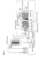
- FIG. 1 is a cross-sectional view schematically illustrating configurations of a diesel particulate removing apparatus of an embodiment of the present invention.
- the diesel particulate removing apparatus is mounted on a diesel engine vehicle and, as shown in Fig. 1, is connected to an exhaust gas path 2 of a diesel engine 1.
- the diesel particulate removing apparatus is made up of an outer cylinder 4 having apertures on sides of flow-in and flow-out of diesel exhaust gas 3 and two or more filter units (two filter units in the embodiment) 5 which are mounted within the outer cylinder 4 and which collect particulates in the diesel exhaust gas 3 or collect and burn collected particulates to remove them.
- the two filter units 5 connected to each other in a direction along a flow of the diesel exhaust gas 3.
- the combination of these two filter units 5, a flow-in cylinder 6, and a flow-out cylinder 7 makes up a sealed-structured inner cylinder 8, with portions on sides of the flow-in and flow-out of the exhaust gas 3 being not included in the sealed structure.
- the outer cylinder 4 and the inner cylinder 8 are so configured so that the outer and inner cylinders are of a dual-cylinder structure, as a whole.
- FIG. 2 is an exploded view showing inner configurations of the diesel particulate removing apparatus according to the embodiment of the present invention.
- Figure 3 is a plan view showing an outer appearance of the diesel particulate removing apparatus according to the embodiment.
- Figure 4 is a diagram illustrating a state in which filter units are being mounted in the diesel particulate removing apparatus according to the embodiment.
- Figure 5 is a perspective view showing configurations of a detachable unit employed in the diesel particulate removing apparatus according to the embodiment.
- Figure 6 is a cutaway cross-sectional view illustrating an entire mechanical configuration of the diesel particulate removing apparatus according to the embodiment. As shown in Figs.
- the two cylindrical PM (Particulate Material being black smoke) removing filter units 5 (including the front filter unit 5 and rear filter unit 5), a joint cylinder 9 having a gasket (not shown) used to connect the front filter units 5 to the rear filter unit 5, the flow-in cylinder 6, and the flow-out cylinder 7, are all tightened by an attaching and detaching means 12 (shown as 13A and 13B in Fig. 2) which make up the sealed-structured inner cylinder 8.
- the flow-in cylinder 6 and a front lid portion 8B in the inner cylinder 8 are welded to each other and the flow-out cylinder 7 and a rear lid portion 8C in the inner cylinder 8 are welded to each other.
- the ring-shaped gasket (not shown). Between the filter unit 5 mounted on a downstream side and the rear lid portion 8C (for the flow-out cylinder 7) is also inserted the ring-shaped gasket (not shown) .
- These gaskets ensure the sealed structure.
- These ring-shaped gaskets are composed by ring-shaped metal plates. And two faces of the ring-shaped metal plate are coating with carbon particulates. As shown in Fig.
- each of the filter units 5 chiefly includes a shorter inner cylinder portion 5A, a roll-shaped filter portion 5B mounted so as to have a common axial center with the inner cylinder portion 5A, a cross-shaped filter receiver 5C, and a three piece composed or a four piece composed blade 5D which is mounted in an axial direction.
- the three piece composed or the four piece composed blade 5D contributes to secure a cross-zonal clearance (an emergency bypass flow-path K) between a external surrounding surface of the inner cylinder 8 and an inner surrounding surface of the outer cylinder 4.
- a disc spring 20 and a by-pass valve (safety valve) 15 are attached to the front lid portion 8B including the flow-in cylinder 6 as will be described later.
- the outer cylinder 4 chiefly includes a longer outer cylinder portion 4A having apertures on its both sides, a front lid portion 4B, and a cylindrical rear lid portion 4C.
- the front lid portion 4B has an aperture used to let the flow-in cylinder 6 be inserted in the inner cylinder 8.
- the cylindrical rear lid portion 4C has an aperture used to let the flow-out cylinder 7 be inserted in the inner cylinder 8.
- on side surfaces surrounding the outer cylinder 4 are formed aperture portions 11 with side lids 10, which are used to attach and detach the filter units 5 or a like.
- the attaching and detaching means 12 to be used freely to attach and detach the inner cylinder 8 and the outer cylinder 4 that houses the inner cylinder 8.
- the attaching and detaching means 12 is made up of single, or two or more (in the embodiment) long bolts 13A, 13A, ⁇ and nuts 13B, 13B, ⁇ (preferably, double nuts) .
- a force receiving plate 13C On side surface surrounding the flow-out cylinder 7 in the inner cylinder 8 is fitted and welded a force receiving plate 13C which is used to receive pressing force from the above long bolts 13A, 13A, ⁇ .
- a disc spring 14 made up of a flat spring member to be used to press the inner cylinder 8 to the outer cylinder 4 for fastening through the disc spring 20 and to absorb thermal expansion.
- an aperture In a central portion of the disc spring 14 is formed an aperture to let the flow-in cylinder 6 in the inner cylinder 4 be inserted.
- the diesel particulate removing apparatus of the embodiment is so configured that, while a diesel engine is driven, at time of a rapid increase in pressure of the exhaust gas 3 in the inner cylinder 8 caused for some reason, a cross-zonal clearance between an external surrounding surface of the inner cylinder 8 and an internal surrounding surface of the outer cylinder 4 serves as an emergency bypass flow-path K which prevents explosive burning such as oxygen flash or a like (see Figs. 1 and 6). Therefore, a by-pass valve (safety valve) 15 is mounted which is used to let the exhaust gas 3 be flown through the emergency bypass flow-path K when the pressure in the inner cylinder 8 increases rapidly (see Fig. 1).
- a valve bar blocks the by-pass valve 15 with a spring force of a compressed coil spring (not shown), otherwise, on a time of emergency, when the exhaust pressure in the inner-cylinder 8 exceeds a specified value the valve bar is backed away and the by-pass valve 15 is opened.
- the exhaust gas in the inner-cylinder 8 is flown into the cross-zonal clearance between the external surrounding surface of the inner cylinder 8 and the internal surrounding surface of the outer cylinder 4 (the emergency bypass flow-path K) and the exhaust gas in the inner-cylinder 8 is exhausted outside of the inner-cylinder 8.
- an emergency exhaust exit that serves as an exit for the exhaust gas 3 flown through the emergency bypass flow-path K.
- pressure sensors (clogging alerting sensor) 16 to alert operators to clogging of a mesh of the filter units 5 are attached to a side of an upstream of the exhaust gas 3 and to a side of a downstream of the exhaust gas 3.
- a temperature sensor T is mounted in a central portion of the apparatus.
- a collision plate 17 On the side of the upstream of the exhaust gas 3' in the front filter unit 5 is mounted a collision plate 17 adapted to reduce a speed of flow of the diesel exhaust gas 3 flowing out of the flow-in cylinder 6 at a high speed and to disperse the exhaust gas 3 uniformly within the filter unit 5.
- a filter portion 5B being a core portion of the filter unit 5 is described by referring to Figs. 8 to 10.
- the filter portion 5B chiefly includes platinum oxidized catalyst 18 supported by a metal mesh mounted on the side of upstream of the exhaust gas 3 and a metal filter 19.
- Figure 8 is a partially expanded view schematically illustrating configurations of the metal filter 19 being embedded in each of the filter units 5 making up the diesel particulate removing apparatus.
- the metal filter 19 of the embodiment as shown in Fig.
- the diesel particulates are made to pass through an interlayer clearance between the metal porous bodies 103 to collect and remove black smoke particulates contained in the diesel exhaust gas 3.
- the above through holes 102 are formed in a crest portion M and a trough portion v making up the column-like rising and falling.
- the protrusion with a surface 101 is formed in a manner in which it protrudes on a side of the column-like concave portion 105.
- Figure 9 is a partially expanded cross-sectional view schematically illustrating configurations of another metal filter to be embedded in each of the filter units 5 making up the diesel particulate removing apparatus.
- Figure 10 is also a partially expanded perspective view schematically illustrating configurations of still another metal filter to be embedded in the diesel particulate removing apparatus of the embodiment.
- the another metal filter as shown in Figs. 9 and 10, is constructed by winding up wave-shaped metal plates 26 that repeat sinusoidal-wave-like rising and falling and metal plates 27 being approximately flat compared with the wave-shaped metal plates 26 and having the approximately same width as that of wave-shaped metal plates 26, with each of the metal plates 26 and each of the metal plates 27 being overlapped one another, in a multi-layer manner.
- a plurality of through holes 29 each having a protrusion with a surface 28 in an end portion is formed in each of the wave-shaped metal plates 26.
- the metal plates 26 each repeating a sinusoidal-wave-like rising and falling are wound in a multi-layer vortex-like manner make up a roll metal porous body 30.
- a plurality of through holes 31 having no protrusion with surfaces is formed on each of the metal plates 27.
- a long bolt 13A serving as an attaching and detaching means 12 is inserted into a bolt inserting hole formed in the rear lid portion 4C of the outer cylinder 4 and, by using a tool, a nut (double nut) 13B is screwed in to press a disc spring 14 into a clearance in an axial direction between the inner cylinder 8 and outer cylinder 4 on a flow-in side (see Figs. 7, 11, and 12).
- the disc spring 14 is deformed by the pressure, thus causing the inner cylinder 8 to be fixed to the outer cylinder 4 by pressure to form the inner cylinder 8 of a sealed-structure.
- the black smoke particulate removing apparatus having the configurations as above is used in a diesel engine vehicle, that is, it is embedded into an exhaust gas path of a diesel engine for use.
- a diesel engine is being operated, as shown in Fig. 8
- the protrusion with a surface 101 acts as an obstacle to a flow F of the exhaust gas, more particularly, as a collision plate, flow speed reducing plate, turn plate, or through hole introducing plate
- unburned black smoke particulates flying in the exhaust gas are easily collected by a surface or rear face of the metal filter 19 existing in the vicinity of the protrusion with the surface 101 and/or the through hole 102.
- Part of the unburned black smoke particulates collected by the metal filter 19 is heated and burnt by the high-temperature metal filter 19 or in the atmosphere (that is, in the exhaust gas) and removed from the metal filter 19, while remaining parts remain adhered to the metal filter 19.
- the exhaust gas 3 having passed through the metal filter 19 is exhausted as normal gas containing no black smoke particulates.
- the filter unit 5 metal filter 19
- the pressure sensors 16 clogging alerting sensor
- the operator disassembles the inner cylinder 8 and takes out the mesh-clogged filter units 5.
- the side lids 10 of the aperture portions 11 for attaching and detaching are opened and, using a tool, a long bolt 13A serving as an attaching and detaching means 12 mounted on the rear lid 4C in the outer cylinder 4 is loosened.
- the disc spring 14 is released from pressure which causes each components of the inner cylinder 8 (each of filter units 5, joint cylinder 9 with the gasket, front lid portion 8B on the side of the flow-in cylinder 6, and rear lid portion 8C on the side of the flow-out cylinder 7 (see Figs. 7, 11 and 12) to be disconnected and disassembled.
- the operator takes out the clogged filter units 5 from the released aperture portions 11 for attaching and detaching and heats them in an exclusive regeneration furnace for specified time and for a specified temperature. By the heating, unburned particulates which have caused the clogging of the mesh of the filter units 5 are burnt and, as a result, functions of the filter units 5 are regenerated.
- components to be taken from the aperture portions 11 for attaching and detaching are not limited to the filter units 5. If necessary, the joint cylinder 9 with the gasket, front lid portion 8B (flow-in cylinder 6) , and rear lid portion 8C (flow-out cylinder 7 ) may be taken out, or these components may be left in the outer cylinder 4.
- the side lids 10 of the aperture portions 11 for attaching and detaching are again opened and each of the filter units 5 is inserted from the aperture portions 11.
- the long bolt 13A serving as the attaching and detaching means 12 is inserted into the bolt inserting hole of the rear lid 4C in the outer cylinder 4 and then the nut (double nut) 13B is screwed in to press the inserted disc spring 14 into the clearance in an axial direction between the inner cylinder 8 and outer cylinder 4 on the side of the flow-in of the exhaust gas 3 (see Figs. 7, 11 and 12).
- the long bolt 13A is fastened, the disc spring 14 is deformed by pressure and then the inner cylinder 8 is pressed on the outer cylinder 4 to be fixed and the inner cylinder 8 of a sealed structure is again formed and re-mounting is now completed.
- bypass valve (safety valve) 15 opens.
- the high-pressure exhaust gas 3 is exhausted through the opened bypass valve (safety valve) and then through the emergency bypass flow-path K between the external surrounding surface of the inner cylinder 8 and the inner surrounding surface of the outer cylinder 4 from an emergency exhaust hole formed in the rear lid portion 4C in the outer cylinder 4 (see Figs. 1 and 6).
- a danger and/or uncomfortable state caused by explosive burning such as oxygen flash or a like can be prevented.
- the attaching and detaching means 12 to connect the inner cylinder 8 and outer cylinder 4 so as to be freely attached or detached is mounted on a flow-out side of the exhaust gas 3.
- the attaching and detaching means 12 may be mounted on the flow-in side of the exhaust gas 3.
- the attaching and detaching means is not limited to the long bolts 13A, 13A, ⁇ and the nuts (double nuts) 13B, 13B, ⁇ .
- a flat spring member (disc spring 14) is mounted in a clearance in an axial direction between the front lid section 8B in the inner cylinder 8 and the front lid portion 4B in the outer cylinder 4.
- the flat spring member may be mounted between the rear lid portion 8C in the inner cylinder 8 and the rear lid portion 4C in the outer cylinder 4.
- the flat spring member is not limited to a disc spring.
- the particulate removing apparatus of the present invention can be applied not only to a diesel engine vehicle but also to all internal combustion engines, for example any internal combustion engine used for an emergency generator, a personal generator, an agricultural implement, and a like. Furthermore, the particulate removing apparatus of the present invention is not limited to be attached to an exhaust gas path of a diesel exhaust gas and it is valuable to be attached to a flow path of different kinds of gases.
Landscapes
- Engineering & Computer Science (AREA)
- Chemical & Material Sciences (AREA)
- Combustion & Propulsion (AREA)
- Mechanical Engineering (AREA)
- General Engineering & Computer Science (AREA)
- Processes For Solid Components From Exhaust (AREA)
Abstract
Description
- The present invention relates to a particulate removing apparatus and more particularly to the particulate removing apparatus which is preferable to be adapted to collect particulates contained in exhaust gas from an internal combustion engine such as an diesel engine or a like used for a diesel engine vehicle, an electric generator, an agricultural implement, or like by using a heater and a filter and to burn and remove the collected particulates and to the diesel engine vehicle equipped with the particulate removing apparatus.
- The present application claims two priorities of Japanese Patent Application No. 2003-359980 filed on September 10, 2003, and No. 2003-424409 filed on December 22, 2003, which are hereby incorporated by reference.
- In emission regulations on exhaust gas from vehicles, attention has been directed conventionally to nitrogen oxide (NOx) or a like which mainly contains nitrogen dioxide being considered as a carcinogen. Exhaust gas from a diesel engine vehicle contains a large amount of carbon particulates (so-called black smoke) . The carbon particulates, after having been puffed out through an exhaust gas path in the air, remain suspended in the air for a long time and, in the end, settle, in a form of soot or a like, onto a floor surface, road surface, clothes, or a like. In recent years; reports have been successively made that, since carbon making up such the carbon particulates easily adsorbs substances, various chemical substances such as carcinogenesis related substances are adsorbed by the carbon particulates flying in the air and humans inhales the carbon particulates which enter the human body, thus causing cancers or respiratory diseases.
- In such a circumstance, particulate materials (PM) exhausted from a diesel engine vehicle, in addition to NOx, present a significant problem in emission regulations. To try to solve this problem, a black smoke removing apparatus is disclosed in, for example, Japanese Model Utility Application Nos. Sho 61 - 55114 and Sho 61 - 84851 in which, as an apparatus to protect environmental air from diesel black smoke pollution, a black smoke removing filter made up of a metal fiber, a honeycomb-shaped element or a like is attached to an exhaust gas path of a vehicle-mounted diesel engine. However, such the black smoke removing filter as disclosed above has a shortcoming that its long time use causes clogging of a mesh of the filter due to collected black smoke, which causes a loss of pressure. As a means for solving the problem of clogging of a mesh caused by black smoke, a diesel particulate removing.apparatus is disclosed in, for example, Japanese Patent Application Laid-open Nos. Hei 2 - 173310, Hei 6 - 212954 and Hei 8 - 1935'09 in which a filtering function is regenerated by burning collected diesel particulates. The apparatus of this type is made up of a cylindrical container having an entrance and an exit of exhaust gas, a heater mounted on a side of the entrance of the cylindrical container, a porous foam filter arranged so as to be adjacent to a rear portion of the heater, and a catalyst supporting filter arranged so as to be adjacent to a rear portion of the porous foam filter.
- The particulate removing apparatus having such the configurations as above is so configured that exhaust gas introduced from the entrance comes into contact with the heater made of ceramic or metal and already heated, causing ignition and burning of the particulates and the burnt particulates are then collected by the porous foam filter and by the catalyst supporting filter. At this time point, the heat generated by the heater and given off by the exhaust gas is transmitted to the porous foam filter and lets unburned particulates collected by the porous foam filter be ignited and burnt. In the catalyst supporting filter mounted on a lower stream side, since an amount of the heat transmitted from the heater and exhaust gas becomes small, though its temperature becomes low, burning of collected particulates is facilitated by the catalyst supported by the catalyst supporting filter and,.therefore, ignition does not occur and most of collected particulates are burnt and removed at a comparatively low temperature, which, as a result, regenerates functions of the clogged filter.
- However, such the conventional particulate removing apparatus has a problem. That is, the configuration in which functions of the filter are to be generated by the heater embedded in the apparatus is idealistic, however, it is complex, expensive, and inferior in durability.
- On the other hand, even in a filter in which no clogging of a mesh has occurred, if a large amount of exhaust gas containing large amounts of oxygen, together with black smoke, flows rapidly into a diesel particulate removing apparatus, a phenomenon in which unburned particulates burns in an explosive manner, that is, a phenomenon called "oxygen flash" occurs in the diesel particulate removing apparatus which arouses a fear of a damage of the filter or a like. For example, in a long descent or a like, if a driver presses down on an accelerator after having used an exhaust brake adapted to brake a diesel engine by stopping the exhaust, exhaust gas containing oxygen at a high concentration (for example, being four times higher than usual), together with diesel particulates, flows rapidly into the diesel particulate removing apparatus which causes the diesel particulates to burn in an explosive manner and the temperature generated by the burning reaches up to about 1500°C, thus arousing a fear of melting of, for example, a metal filter.
- In view of the above, it is an object of the present invention to provide a particulate removing apparatus being capable of regenerating, with ease and at a low cost, a function of a filter in which advanced clogging of its mesh has occurred and a diesel engine vehicle equipped with the diesel particulate removing apparatus. It is another object of the present invention to provide a particulate removing apparatus which is capable of preventing explosive burning of particulates in a gas caused for some reason and of preventing, even if the explosive burning occurs, burning of the diesel particulate removing apparatus itself and a diesel engine vehicle equipped with the diesel particulate removing apparatus.
- According to a first aspect of the present invention, there is provided a diesel particulate removing apparatus including:
- an outer cylinder being attached, in an embedded manner, to an exhaust gas path of a diesel engine and having apertures on sides of flow-in and flow-out of diesel exhaust gas; and
- at least one filter being mounted in the outer cylinder to collect, or to collect and burn particulates contained in the diesel exhaust gas to remove them; wherein the at least one filter make up an inner cylinder and wherein a clearance between the inner cylinder and the outer cylinder functions as an emergency bypass flow-path to be used when pressure in the inner cylinder increases rapidly.
-
- In the foregoing, a preferable mode is one wherein a safety valve is mounted in the inner cylinder, which is used to let the diesel exhaust gas flow into the emergency bypass flow-path when pressure in the inner cylinder increases rapidly.
- Also, a preferable mode is one wherein apertures with lids to attach and detach the two or more filters are mounted on side surfaces of the outer cylinder.
- Also, a preferable mode is one that wherein includes:
- an outer cylinder being attached, in an embedded manner, to an exhaust gas path of a diesel engine and having apertures on sides of flow-in and flow-out of diesel exhaust gas; and
- two or more filters being mounted in the outer cylinder to collect, or to collect and burn particulates contained in the diesel exhaust gas to remove; wherein the two or more filters are connected to each other in a direction along a flow of the diesel exhaust gas and are combined with a flow-in cylinder and a flow-out cylinder for the diesel exhaust gas to make up the inner cylinder of a sealed structure, with portions on sides of flow-in and flow-out of the diesel exhaust gas being not included in the sealed structure.
-
- A preferable mode is one wherein gaskets are inserted between the two or more filters, between one of the two or more filters placed on a most upstream side and the flow-in cylinder, and between one of the two or more filters placed on a most downstream side and the flow-out cylinder, which make up the inner cylinder of a sealed structure.
- Also, a preferable mode is one wherein a joint cylinder with the gaskets to connect the two or more filters each other is mounted in the inner cylinder.
- Also, a preferable mode is one wherein aperture portions with lids to attach and detach each of the two or more filters are formed on a side surface of the outer cylinder.
- Also, a preferable mode is one wherein, to mount the inner cylinder, lid portions of the apertures for attaching and detaching are opened and then each of the filters is inserted from each of the apertures for attaching and detaching and, to disassemble the inner cylinder, an attaching and detaching unit to take out each of the two or more filters from each of the apertures for attaching and detaching is used.
- Also, a preferable mode is one wherein the attaching and detaching unit. has a single long bolt or two or more long bolts.
- Also, a preferable mode is one wherein the attaching and detaching unit has a single long bolt or two or more long bolts and a single double-nut or two or more double-nuts.
- Also, a preferable mode is one wherein a flat spring member to fix the outer cylinder and inner cylinder and to absorb thermal expansion is mounted in a clearance in an axial direction between the inner cylinder on a side of flow-out or on a side of flow-in of exhaust gas and the outer cylinder.
- Also, a preferable mode is one wherein the long bolt for the attaching and detaching unit'is inserted into an end portion on a side of flow-in or on a side of flow-out of exhaust gas in the outer cylinder and the flat spring member to absorb thermal expansion is mounted in a clearance in an axial direction between the inner cylinder on the side of flow-out or on the side of the flow-in of exhaust gas and the outer cylinder wherein, when the long bolt is fastened, the flat spring member is deformed by pressure which causes the inner cylinder to be fixed to the outer cylinder.
- Also, a preferable mode is one wherein the flat spring member includes a disc spring in a central portion of which an aperture to let the flow-in cylinder or flow-out cylinder be inserted is formed.
- Furthermore, a preferable mode is one wherein a clogging alerting sensor to alert an operator to clogging in a mesh of each of the two or'more filters.
- According to a third aspect of the present invention, there is provided a diesel engine vehicle being equipped with the diesel particulate removing apparatus described above.
- With the above configuration, a function of a filter in which advanced clogging of its mesh has occurred can be regenerated with ease and at a low cost. Also, explosive burning of diesel particulates caused for some reason can be prevented and even if the explosive burning occurs, burning of the diesel particulate removing apparatus itself can be prevented.
- The above and other objects, advantages, and features of the present invention will be more apparent from the following description taken in conjunction with the accompanying drawings in which:
- Fig. 1 is a cross-sectional view schematically illustrating configurations of a diesel particulate removing apparatus according to an embodiment of the present invention;
- Fig. 2 is an exploded view showing inner configurations of the diesel particulate removing apparatus according to the embodiment of the present invention;
- Fig. 3 is a plan view showing an outer appearance of the diesel particulate removing apparatus according to the embodiment of the present invention;
- Fig. 4 is a diagram illustrating a state in which filter units are being mounted in the diesel particulate removing apparatus according to the embodiment of the present invention;
- Fig. 5 is a perspective view showing configurations of a detachable unit employed in the diesel particulate removing apparatus according to the'embodiment of the present invention;
- Fig. 6 is a cutaway cross-sectional view illustrating an entire mechanical configuration of the diesel particulate removing apparatus according to the embodiment of the present invention;
- Fig. 7 is a photo illustrating another state in which filter units are being mounted in the diesel particulate removing apparatus according to the embodiment of the present invention;
- Fig. 8 is a partially expanded perspective view schematically illustrating configurations of a metal filter to be embedded in the diesel particulate removing apparatus according to'the embodiment of the present invention;
- Fig. 9 is a partially expanded cross-sectional view schematically illustrating configurations of another metal filter to be embedded in the diesel particulate removing apparatus according to the embodiment of the present invention;
- Fig. 10 is a partially expanded perspective view schematically illustrating configurations of still another metal filter to be embedded in the diesel particulate removing apparatus according to the embodiment of the present invention;
- Fig. 11 is a photo showing a state in which the filter units are attached and detached in the diesel particulate removing apparatus according to the embodiment of the present invention; and
- Fig. 12 is a photo showing a state in which the filter units are attached and detached in the diesel particulate removing apparatus according to the embodiment of the present invention.
-
- Best modes of carrying out the present invention will be described in further detail using various embodiments with reference to the accompanying drawings. An aim of regenerating, at ease and at a low cost, a function of a filter in which advanced clogging of its mesh has occurred is achieved by constructing an outer cylinder and an inner cylinder made up of filters or a like so that the outer and inner cylinders are of a dual-cylinder structure and by forming lid-mounted aperture portions used to attach and detach the filters serving as components of the inner cylinder in the above outer cylinder. Unburned particulates remaining in the filter detached from the outer cylinder are burnt in a regeneration furnace and the function of the filter can be regenerated.
- Figure 1 is a cross-sectional view schematically illustrating configurations of a diesel particulate removing apparatus of an embodiment of the present invention. The diesel particulate removing apparatus is mounted on a diesel engine vehicle and, as shown in Fig. 1, is connected to an
exhaust gas path 2 of adiesel engine 1. The diesel particulate removing apparatus is made up of anouter cylinder 4 having apertures on sides of flow-in and flow-out ofdiesel exhaust gas 3 and two or more filter units (two filter units in the embodiment) 5 which are mounted within theouter cylinder 4 and which collect particulates in thediesel exhaust gas 3 or collect and burn collected particulates to remove them. The twofilter units 5 connected to each other in a direction along a flow of thediesel exhaust gas 3. The combination of these twofilter units 5, a flow-incylinder 6, and a flow-outcylinder 7 makes up a sealed-structuredinner cylinder 8, with portions on sides of the flow-in and flow-out of theexhaust gas 3 being not included in the sealed structure. Thus, theouter cylinder 4 and theinner cylinder 8 are so configured so that the outer and inner cylinders are of a dual-cylinder structure, as a whole. - Inner configurations of the diesel particulate removing apparatus of the embodiment are described by referring to Figs. 2, 3, 4, and 6. Figure 2 is an exploded view showing inner configurations of the diesel particulate removing apparatus according to the embodiment of the present invention. Figure 3 is a plan view showing an outer appearance of the diesel particulate removing apparatus according to the embodiment. Figure 4 is a diagram illustrating a state in which filter units are being mounted in the diesel particulate removing apparatus according to the embodiment. Figure 5 is a perspective view showing configurations of a detachable unit employed in the diesel particulate removing apparatus according to the embodiment. Figure 6 is a cutaway cross-sectional view illustrating an entire mechanical configuration of the diesel particulate removing apparatus according to the embodiment. As shown in Figs. 2 to 6 and as described above, the two cylindrical PM (Particulate Material being black smoke) removing filter units 5 (including the
front filter unit 5 and rear filter unit 5), ajoint cylinder 9 having a gasket (not shown) used to connect thefront filter units 5 to therear filter unit 5, the flow-incylinder 6, and the flow-outcylinder 7, are all tightened by an attaching and detaching means 12 (shown as 13A and 13B in Fig. 2) which make up the sealed-structuredinner cylinder 8. The flow-incylinder 6 and afront lid portion 8B in theinner cylinder 8 are welded to each other and the flow-outcylinder 7 and arear lid portion 8C in theinner cylinder 8 are welded to each other. Between thefilter unit 5 mounted on an upstream side and thefront lid portion 8B (for the flow-in cylinder 6) is inserted the ring-shaped gasket (not shown). Between thefilter unit 5 mounted on a downstream side and therear lid portion 8C (for the flow-out cylinder 7) is also inserted the ring-shaped gasket (not shown) . These gaskets ensure the sealed structure. These ring-shaped gaskets are composed by ring-shaped metal plates. And two faces of the ring-shaped metal plate are coating with carbon particulates. As shown in Fig. 4, each of thefilter units 5 chiefly includes a shorterinner cylinder portion 5A, a roll-shapedfilter portion 5B mounted so as to have a common axial center with theinner cylinder portion 5A, across-shaped filter receiver 5C, and a three piece composed or a four piece composedblade 5D which is mounted in an axial direction. The three piece composed or the four piece composedblade 5D, as described later, contributes to secure a cross-zonal clearance (an emergency bypass flow-path K) between a external surrounding surface of theinner cylinder 8 and an inner surrounding surface of theouter cylinder 4. - Furthermore a
disc spring 20 and a by-pass valve (safety valve) 15 are attached to thefront lid portion 8B including the flow-incylinder 6 as will be described later. - As shown in Fig. 3 and Fig. 6, the
outer cylinder 4 chiefly includes a longerouter cylinder portion 4A having apertures on its both sides, afront lid portion 4B, and a cylindricalrear lid portion 4C. Thefront lid portion 4B has an aperture used to let the flow-incylinder 6 be inserted in theinner cylinder 8. Also, the cylindricalrear lid portion 4C has an aperture used to let the flow-outcylinder 7 be inserted in theinner cylinder 8. Moreover, as shown in Figs. 3 and 4, on side surfaces surrounding theouter cylinder 4 are formedaperture portions 11 withside lids 10, which are used to attach and detach thefilter units 5 or a like. - To the
rear lid portion 4C is attached the attaching and detaching means 12 to be used freely to attach and detach theinner cylinder 8 and theouter cylinder 4 that houses theinner cylinder 8. As shown in Figs. 4 and 5, the attaching and detaching means 12 is made up of single, or two or more (in the embodiment)long bolts cylinder 7 in theinner cylinder 8 is fitted and welded aforce receiving plate 13C which is used to receive pressing force from the abovelong bolts - As shown in Fig. 6, in a clearance in an axial direction between the
inner cylinder 8 andouter cylinder 4, that is, in the clearance in the axial direction between thefront lid portion 8B in theinner cylinder 8 and thefront lid portion 4B in theouter cylinder 4 is formed adisc spring 14 made up of a flat spring member to be used to press theinner cylinder 8 to theouter cylinder 4 for fastening through thedisc spring 20 and to absorb thermal expansion. In a central portion of thedisc spring 14 is formed an aperture to let the flow-incylinder 6 in theinner cylinder 4 be inserted. - The diesel particulate removing apparatus of the embodiment is so configured that, while a diesel engine is driven, at time of a rapid increase in pressure of the
exhaust gas 3 in theinner cylinder 8 caused for some reason, a cross-zonal clearance between an external surrounding surface of theinner cylinder 8 and an internal surrounding surface of theouter cylinder 4 serves as an emergency bypass flow-path K which prevents explosive burning such as oxygen flash or a like (see Figs. 1 and 6). Therefore, a by-pass valve (safety valve) 15 is mounted which is used to let theexhaust gas 3 be flown through the emergency bypass flow-path K when the pressure in theinner cylinder 8 increases rapidly (see Fig. 1). - In the by-
pass valve 15, on a stead basis, a valve bar (not shown) blocks the by-pass valve 15 with a spring force of a compressed coil spring (not shown), otherwise, on a time of emergency, when the exhaust pressure in the inner-cylinder 8 exceeds a specified value the valve bar is backed away and the by-pass valve 15 is opened. As the result through the by-pass valve 15 the exhaust gas in the inner-cylinder 8 is flown into the cross-zonal clearance between the external surrounding surface of theinner cylinder 8 and the internal surrounding surface of the outer cylinder 4 (the emergency bypass flow-path K) and the exhaust gas in the inner-cylinder 8 is exhausted outside of the inner-cylinder 8. - Moreover, in the
rear lid portion 4C in theouter cylinder 4 is formed, in addition to a bolt inserting hole, an emergency exhaust exit that serves as an exit for theexhaust gas 3 flown through the emergency bypass flow-path K. - Also, for safety, pressure sensors (clogging alerting sensor) 16 to alert operators to clogging of a mesh of the
filter units 5 are attached to a side of an upstream of theexhaust gas 3 and to a side of a downstream of theexhaust gas 3. Moreover, a temperature sensor T is mounted in a central portion of the apparatus. On the side of the upstream of the exhaust gas 3' in thefront filter unit 5 is mounted acollision plate 17 adapted to reduce a speed of flow of thediesel exhaust gas 3 flowing out of the flow-incylinder 6 at a high speed and to disperse theexhaust gas 3 uniformly within thefilter unit 5. - Next, a
filter portion 5B being a core portion of thefilter unit 5 is described by referring to Figs. 8 to 10. As shown in Fig. 1, thefilter portion 5B chiefly includes platinum oxidized catalyst 18 supported by a metal mesh mounted on the side of upstream of theexhaust gas 3 and ametal filter 19. Figure 8 is a partially expanded view schematically illustrating configurations of themetal filter 19 being embedded in each of thefilter units 5 making up the diesel particulate removing apparatus. Themetal filter 19 of the embodiment, as shown in Fig. 8, is made up of wave-shaped roll metalporous bodies 103 which are formed by winding up a metal plate that repeats its rising and falling in a manner to form a sinusoidal wave, in a multi-layer vortex-like manner, on which a plurality of throughholes 102 is formed each having a protrusion with asurface 101 in an edge portion. The diesel particulates are made to pass through an interlayer clearance between the metalporous bodies 103 to collect and remove black smoke particulates contained in thediesel exhaust gas 3. The above throughholes 102 are formed in a crest portion M and a trough portion v making up the column-like rising and falling. The protrusion with asurface 101 is formed in a manner in which it protrudes on a side of the column-likeconcave portion 105. - Figure 9 is a partially expanded cross-sectional view schematically illustrating configurations of another metal filter to be embedded in each of the
filter units 5 making up the diesel particulate removing apparatus. Figure 10 is also a partially expanded perspective view schematically illustrating configurations of still another metal filter to be embedded in the diesel particulate removing apparatus of the embodiment. The another metal filter, as shown in Figs. 9 and 10, is constructed by winding up wave-shapedmetal plates 26 that repeat sinusoidal-wave-like rising and falling andmetal plates 27 being approximately flat compared with the wave-shapedmetal plates 26 and having the approximately same width as that of wave-shapedmetal plates 26, with each of themetal plates 26 and each of themetal plates 27 being overlapped one another, in a multi-layer manner. A plurality of throughholes 29 each having a protrusion with asurface 28 in an end portion is formed in each of the wave-shapedmetal plates 26. Themetal plates 26 each repeating a sinusoidal-wave-like rising and falling are wound in a multi-layer vortex-like manner make up a roll metalporous body 30. A plurality of throughholes 31 having no protrusion with surfaces is formed on each of themetal plates 27. - Next, operations of the diesel particulate removing apparatus of the embodiment are explained.
- To attach the
filter units 5 to theouter cylinder 4, in other words, to insert theinner cylinder 8 into theouter cylinder 4 for assembly, in a state in which thefront lid portion 8B (flow-in cylinder 6) and therear lid portion 8C (flow-out cylinder 7) are mounted in advance in theouter cylinder 4, side lids 10 of theaperture portions 11 for attaching and detaching are opened first and each of thefilter units 5,joint cylinder 9 with a gasket, gaskets of another kind (not shown) are inserted from theaperture portions 11 for attaching and detaching. Next, along bolt 13A serving as an attaching and detaching means 12 is inserted into a bolt inserting hole formed in therear lid portion 4C of theouter cylinder 4 and, by using a tool, a nut (double nut) 13B is screwed in to press adisc spring 14 into a clearance in an axial direction between theinner cylinder 8 andouter cylinder 4 on a flow-in side (see Figs. 7, 11, and 12). When thelong bolt 13A is fastened, thedisc spring 14 is deformed by the pressure, thus causing theinner cylinder 8 to be fixed to theouter cylinder 4 by pressure to form theinner cylinder 8 of a sealed-structure. - The black smoke particulate removing apparatus having the configurations as above is used in a diesel engine vehicle, that is, it is embedded into an exhaust gas path of a diesel engine for use. In the black smoke particulate removing apparatus, while a diesel engine is being operated, as shown in Fig. 8, at time when a diesel exhaust gas passes through the interlayer clearance of the
metal filter 19, since the protrusion with asurface 101 acts as an obstacle to a flow F of the exhaust gas, more particularly, as a collision plate, flow speed reducing plate, turn plate, or through hole introducing plate, unburned black smoke particulates flying in the exhaust gas are easily collected by a surface or rear face of themetal filter 19 existing in the vicinity of the protrusion with thesurface 101 and/or the throughhole 102. Part of the unburned black smoke particulates collected by themetal filter 19 is heated and burnt by the high-temperature metal filter 19 or in the atmosphere (that is, in the exhaust gas) and removed from themetal filter 19, while remaining parts remain adhered to themetal filter 19. As a result, theexhaust gas 3 having passed through themetal filter 19 is exhausted as normal gas containing no black smoke particulates. - When clogging of the mesh occurs the filter unit 5 (metal filter 19), the pressure sensors 16 (clogging alerting sensor) alerts an operator to the clogging of the mesh of the
filter units 5. After that, the operator disassembles theinner cylinder 8 and takes out the mesh-cloggedfilter units 5. To take out the mesh-cloggedfilter units 5, the side lids 10 of theaperture portions 11 for attaching and detaching are opened and, using a tool, along bolt 13A serving as an attaching and detaching means 12 mounted on therear lid 4C in theouter cylinder 4 is loosened. Then, thedisc spring 14 is released from pressure which causes each components of the inner cylinder 8 (each offilter units 5,joint cylinder 9 with the gasket,front lid portion 8B on the side of the flow-incylinder 6, andrear lid portion 8C on the side of the flow-out cylinder 7 (see Figs. 7, 11 and 12) to be disconnected and disassembled. After that, the operator takes out the cloggedfilter units 5 from the releasedaperture portions 11 for attaching and detaching and heats them in an exclusive regeneration furnace for specified time and for a specified temperature. By the heating, unburned particulates which have caused the clogging of the mesh of thefilter units 5 are burnt and, as a result, functions of thefilter units 5 are regenerated. Moreover, components to be taken from theaperture portions 11 for attaching and detaching are not limited to thefilter units 5. If necessary, thejoint cylinder 9 with the gasket,front lid portion 8B (flow-in cylinder 6) , andrear lid portion 8C (flow-out cylinder 7 ) may be taken out, or these components may be left in theouter cylinder 4. - To re-mount the
filter units 5 in theouter cylinder 4, the side lids 10 of theaperture portions 11 for attaching and detaching are again opened and each of thefilter units 5 is inserted from theaperture portions 11. Next, thelong bolt 13A serving as the attaching and detaching means 12 is inserted into the bolt inserting hole of therear lid 4C in theouter cylinder 4 and then the nut (double nut) 13B is screwed in to press the inserteddisc spring 14 into the clearance in an axial direction between theinner cylinder 8 andouter cylinder 4 on the side of the flow-in of the exhaust gas 3 (see Figs. 7, 11 and 12). When thelong bolt 13A is fastened, thedisc spring 14 is deformed by pressure and then theinner cylinder 8 is pressed on theouter cylinder 4 to be fixed and theinner cylinder 8 of a sealed structure is again formed and re-mounting is now completed. - While the diesel engine is being operated, if pressure of the
exhaust gas 3 in theinner cylinder 8 increases rapidly for some reason, the bypass valve (safety valve) 15 opens. As a result, the high-pressure exhaust gas 3 is exhausted through the opened bypass valve (safety valve) and then through the emergency bypass flow-path K between the external surrounding surface of theinner cylinder 8 and the inner surrounding surface of theouter cylinder 4 from an emergency exhaust hole formed in therear lid portion 4C in the outer cylinder 4 (see Figs. 1 and 6). Thus, a danger and/or uncomfortable state caused by explosive burning such as oxygen flash or a like can be prevented. - It is apparent that the present invention is not limited to the above embodiments but may be changed and modified without departing from the scope and spirit of the invention. For example, in the above embodiment, the attaching and detaching means 12 to connect the
inner cylinder 8 andouter cylinder 4 so as to be freely attached or detached is mounted on a flow-out side of theexhaust gas 3. However, the attaching and detaching means 12 may be mounted on the flow-in side of theexhaust gas 3. The attaching and detaching means is not limited to thelong bolts front lid section 8B in theinner cylinder 8 and thefront lid portion 4B in theouter cylinder 4. However, the flat spring member may be mounted between therear lid portion 8C in theinner cylinder 8 and therear lid portion 4C in theouter cylinder 4. The flat spring member is not limited to a disc spring. - Moreover, the particulate removing apparatus of the present invention can be applied not only to a diesel engine vehicle but also to all internal combustion engines, for example any internal combustion engine used for an emergency generator, a personal generator, an agricultural implement, and a like. Furthermore, the particulate removing apparatus of the present invention is not limited to be attached to an exhaust gas path of a diesel exhaust gas and it is valuable to be attached to a flow path of different kinds of gases.
Claims (16)
- A particulate removing apparatus characterized by comprising:wherein said at least one filter (5, 5) make up an inner cylinder (8) and wherein a clearance between said inner cylinder (8) and said outer cylinder (4) functions as an emergency bypass flow-path to be used when pressure in said inner cylinder (8) increases rapidly.an outer cylinder (4) being attached, in an embedded manner, to an exhaust gas path (2) and having apertures on sides of flow-in and flow-out of exhaust gas; andat least one filter (5, 5) being mounted in said outer cylinder (4) to collect, or to collect and burn particulates contained in said exhaust gas to remove them;
- The particulate removing apparatus according to Claim 1, wherein a safety valve is mounted in said inner cylinder (8), which is used to let said exhaust gas flow into said emergency bypass flow-path when pressure in said inner cylinder (8) increases rapidly.
- The particulate removing apparatus according to Claim 1, wherein apertures with lids to attach and detach said two or more filters (5, 5) are mounted on side surfaces of said outer cylinder (4).
- A particulate removing apparatus according to Claim 1, comprising:wherein said two or more filters (5, 5) are connected to each other in a direction along a flow of said exhaust gas and are combined with a flow-in cylinder (6) and a flow-out cylinder (7) for said exhaust gas to make up said inner cylinder (8) of a sealed structure, with portions on sides of flow-in and flow-out of said exhaust gas being not included in said sealed structure.an outer cylinder (4) being attached, in an embedded manner, to an exhaust gas path (2) and having apertures on sides of flow-in and flow-out of exhaust gas; andtwo or more filters (5, 5) being mounted in said outer cylinder (4) to collect, or to collect and burn particulates contained in said exhaust gas to remove;
- The particulate removing apparatus according to Claim 4, wherein gaskets are inserted between said two or more filters (5, 5), between one of said two or more filters (5, 5) placed on a most upstream side and said flow-in cylinder (6) , and between one of said two or more filters (5, 5) placed on a most downstream side and said flow-out cylinder, which make up said inner cylinder (8) of a sealed structure.
- The particulate removing apparatus according to Claim 5, wherein a joint cylinder with said gaskets to connect said two or more filters (5, 5) each other is mounted in said inner cylinder (8).
- The particulate removing apparatus according to Claim 4, wherein aperture portions with lids to attach and detach each of said two or more filters (5, 5) are formed on a side surface of said outer cylinder (4).
- The particulate removing apparatus according to Claim 7, wherein, to mount said inner cylinder (8), lid portions of said apertures for attaching and detaching are opened and then each of said filters (5, 5) is inserted from each of said apertures for attaching and detaching and, to disassemble said inner cylinder (8), an attaching and detaching unit to take out each of said two or more filters (5, 5) from each of said apertures for attaching and detaching is used.
- The particulate removing apparatus according to Claim 8, wherein said attaching and detaching unit has a single long bolt or two or more long bolts.
- The particulate removing apparatus according to Claim 8, wherein said attaching and detaching unit has a single long bolt or two or more long bolts and a single double nut or two or more double nuts.
- The particulate removing apparatus according to Claim 4, wherein a flat spring member to fix said outer cylinder (4) and inner cylinder (8) and to absorb thermal expansion is mounted in a clearance in an axial direction between said inner cylinder (8) on a side of flow-out or on a side of flow-in of exhaust gas and said outer cylinder (4).
- The particulate removing apparatus according to Claim 4, wherein, to mount said inner cylinder (8), lid portions of said apertures for attaching and detaching are opened and then each of said filters (5, 5) is inserted from each of said apertures for attaching and detaching and, to disassemble said inner cylinder (8), an attaching and detaching unit having a single long bolt or two or more long bolts to take out each of said two or more filters (5, 5) from each of said apertures for attaching and detaching is used, said long bolt for said attaching and detaching unit is inserted into an end portion on a side of flow-in or on a side of flow-out of exhaust gas in said outer cylinder (4) and said flat spring member to absorb thermal expansion is mounted in a clearance in an axial direction between said inner cylinder (8) on side of said flow-out or on side of said flow-in of exhaust gas and said outer cylinder (4) wherein, when said long bolt is fastened, said flat spring member is deformed by pressure which causes said inner cylinder (8) to be fixed to said outer cylinder (4).
- The particulate removing apparatus according to Claim 12, wherein said flat spring member comprises a disc spring in a central portion of which an aperture to let said flow-in cylinder (6) or flow-out cylinder (7) be inserted is formed.
- The particulate removing apparatus according to Claim 1, wherein a clogging alerting sensor to alert an operator to clogging in a mesh of said two or more filters (5, 5).
- A particulate removing apparatus, as stated in Claim 1, comprising:an outer cylinder (4) being attached, in an embedded manner, to an exhaust gas path (2) of a diesel engine (1) and having apertures on sides of flow-in and flow-out of diesel exhaust gas; andtwo or more filters (5, 5) being mounted in said outer cylinder (4) to collect or to collect and burn particulates contained in said diesel exhaust gas to'remove them.
- A diesel vehicle being equipped with the particulate removing apparatus as stated in Claim 15.
Applications Claiming Priority (4)
| Application Number | Priority Date | Filing Date | Title |
|---|---|---|---|
| JP2003359980 | 2003-09-10 | ||
| JP2003359980 | 2003-09-10 | ||
| JP2003424409 | 2003-12-22 | ||
| JP2003424409 | 2003-12-22 |
Publications (1)
| Publication Number | Publication Date |
|---|---|
| EP1515011A1 true EP1515011A1 (en) | 2005-03-16 |
Family
ID=34138036
Family Applications (1)
| Application Number | Title | Priority Date | Filing Date |
|---|---|---|---|
| EP04021503A Withdrawn EP1515011A1 (en) | 2003-09-10 | 2004-09-10 | Particulate removing apparatus and diesel engine vehicle equipped with same |
Country Status (5)
| Country | Link |
|---|---|
| US (1) | US20050056008A1 (en) |
| EP (1) | EP1515011A1 (en) |
| KR (1) | KR100630037B1 (en) |
| CN (1) | CN1619119A (en) |
| TW (1) | TW200510628A (en) |
Cited By (13)
| Publication number | Priority date | Publication date | Assignee | Title |
|---|---|---|---|---|
| EP1746264A1 (en) * | 2005-06-30 | 2007-01-24 | Sergio Varkala Sangiovani | Constructive disposition in a particulate matter sealing device existing in gas originating from fuel burning and/or chemical reaction when running internal combustion engines |
| EP2110528A1 (en) * | 2008-04-18 | 2009-10-21 | Swenox AB | Apparatus for treating an exhaust gas stream with removable module |
| EP2314835A1 (en) * | 2008-08-11 | 2011-04-27 | Hitachi Construction Machinery Co., Ltd | Exhaust gas purifying device |
| EP2569075A1 (en) * | 2010-05-11 | 2013-03-20 | Stockforsa Invest AB | Method for cleaning of particle filters |
| US8474250B2 (en) | 2006-05-03 | 2013-07-02 | Sabertec L.L.C. | Device and method for the reduction of emissions |
| WO2013102468A1 (en) * | 2012-01-03 | 2013-07-11 | Volvo Lastvagnar Ab | Method and arrangement for cleaning a particle filter |
| CN105240091A (en) * | 2015-10-28 | 2016-01-13 | 台州三元车辆净化器有限公司 | Metal-based diesel vehicle tail gas particle catcher and manufacturing method thereof |
| RU2588326C2 (en) * | 2012-01-03 | 2016-06-27 | Вольво Ластвагнар Аб | Method and system for cleaning filter |
| CN106437984A (en) * | 2016-11-24 | 2017-02-22 | 福州大学 | Diesel engine muffler with charcoal smoke particulate collecting function |
| EP3399165A1 (en) * | 2017-05-04 | 2018-11-07 | Volkswagen Aktiengesellschaft | Exhaust system for an internal combustion engine |
| RU2698860C1 (en) * | 2015-12-31 | 2019-08-30 | Форд Отомотив Санайи А.Ш. | Structurally improved exhaust gas treatment device and corresponding treatment components thereof |
| WO2020074481A1 (en) * | 2018-10-09 | 2020-04-16 | Volvo Truck Corporation | An exhaust aftertreatment unit for an exhaust system of an internal combustion engine |
| DE102011120109C5 (en) * | 2011-12-02 | 2020-07-16 | Man Truck & Bus Se | Combined exhaust aftertreatment / silencing device with cover for mounting and changing exhaust treatment elements |
Families Citing this family (15)
| Publication number | Priority date | Publication date | Assignee | Title |
|---|---|---|---|---|
| US8043394B2 (en) * | 2008-03-21 | 2011-10-25 | GM Global Technology Operations LLC | Particulate matter filter assembly with a flow device |
| US8062602B2 (en) * | 2008-11-25 | 2011-11-22 | Universal Acoustic & Emission Technologies, Inc. | Catalyst housing |
| US20100186381A1 (en) | 2009-01-26 | 2010-07-29 | Caterpillar Inc | Exhaust system thermal enclosure |
| KR20100126163A (en) | 2009-12-04 | 2010-12-01 | 주식회사 알란텀 | Exhaust gas filtering device |
| CN102753797B (en) | 2010-02-12 | 2015-06-17 | 洋马株式会社 | Exhaust gas purification device |
| CN102373988B (en) * | 2010-08-19 | 2014-07-02 | 阿兰图姆公司 | Exhaust gas filtering device |
| WO2013108667A1 (en) * | 2012-01-19 | 2013-07-25 | ヤンマー株式会社 | Exhaust gas purifier |
| DE102013219640A1 (en) | 2013-09-27 | 2015-04-02 | Eberspächer Exhaust Technology GmbH & Co. KG | Exhaust gas treatment device |
| EP3121524A4 (en) * | 2014-03-17 | 2017-11-01 | Sui Chun Law | Air purification device |
| CN104594981B (en) * | 2014-11-29 | 2017-01-11 | 中国煤炭科工集团太原研究院有限公司 | Efficient tail gas particle purification system of mining rubber-tyred vehicle |
| CN107339131B (en) * | 2017-02-14 | 2023-10-13 | 合肥宝发动力技术股份有限公司 | Safety valve DPF purifier |
| SE1950495A1 (en) * | 2019-04-23 | 2020-09-29 | Scania Cv Ab | An emissions control device comprising a threaded disassembling element |
| CN112096484B (en) * | 2020-08-07 | 2021-08-31 | 东风汽车集团有限公司 | Automobile exhaust purifier and automobile |
| CN112627943A (en) * | 2020-11-14 | 2021-04-09 | 河北虹旭环保科技有限公司 | Portable maintenance equipment of DPF |
| US11952929B1 (en) * | 2023-07-13 | 2024-04-09 | Fca Us Llc | Hydracarbon dozer valve pivoting multi purpose bracket |
Citations (7)
| Publication number | Priority date | Publication date | Assignee | Title |
|---|---|---|---|---|
| US3129078A (en) * | 1961-06-16 | 1964-04-14 | Marian L Hobbs | Exhaust muffler filter |
| US3200902A (en) * | 1964-04-07 | 1965-08-17 | Hugh R Jones | Replaceable cartridge acoustical muffler |
| US3224171A (en) * | 1963-08-16 | 1965-12-21 | Hyman D Bowman | Exhaust filter for internal combustion engines |
| US3749130A (en) * | 1971-05-25 | 1973-07-31 | Corning Glass Works | Flow deflector for exhaust gases |
| GB2161396A (en) * | 1984-07-09 | 1986-01-15 | Robert Hammond | Exhaust gas filter system |
| BE1009454A6 (en) * | 1995-06-30 | 1997-03-04 | Poppe Antoine | Filter for diesel engine exhaust gases |
| US20030108457A1 (en) * | 1999-12-09 | 2003-06-12 | Gault Anthony John | Apparatus |
Family Cites Families (7)
| Publication number | Priority date | Publication date | Assignee | Title |
|---|---|---|---|---|
| US2620893A (en) * | 1949-04-28 | 1952-12-09 | Raymond B Holt | Filter for exhaust pipes of internal-combustion engines |
| US3857688A (en) * | 1971-10-27 | 1974-12-31 | Ppg Industries Inc | Lead filter |
| US4946589A (en) * | 1987-02-27 | 1990-08-07 | Combustion Engineering, Inc. | High volume permanent magnet filter for removing ferromagnetic impurities |
| US5410875A (en) * | 1992-08-21 | 1995-05-02 | Nippondenso Co., Ltd. | Exhaust-gas purification device for an internal combustion engine or the like |
| US5396764A (en) * | 1994-02-14 | 1995-03-14 | Ford Motor Company | Spark ignition engine exhaust system |
| JP3434117B2 (en) * | 1996-03-29 | 2003-08-04 | 住友電気工業株式会社 | Particulate trap for diesel engine |
| EP1312776A3 (en) * | 2001-11-16 | 2004-05-12 | Isuzu Motors Limited | Exhaust gas purification system |
-
2004
- 2004-09-09 KR KR1020040072029A patent/KR100630037B1/en not_active IP Right Cessation
- 2004-09-09 TW TW093127281A patent/TW200510628A/en unknown
- 2004-09-09 US US10/936,689 patent/US20050056008A1/en not_active Abandoned
- 2004-09-10 CN CNA2004101038892A patent/CN1619119A/en active Pending
- 2004-09-10 EP EP04021503A patent/EP1515011A1/en not_active Withdrawn
Patent Citations (7)
| Publication number | Priority date | Publication date | Assignee | Title |
|---|---|---|---|---|
| US3129078A (en) * | 1961-06-16 | 1964-04-14 | Marian L Hobbs | Exhaust muffler filter |
| US3224171A (en) * | 1963-08-16 | 1965-12-21 | Hyman D Bowman | Exhaust filter for internal combustion engines |
| US3200902A (en) * | 1964-04-07 | 1965-08-17 | Hugh R Jones | Replaceable cartridge acoustical muffler |
| US3749130A (en) * | 1971-05-25 | 1973-07-31 | Corning Glass Works | Flow deflector for exhaust gases |
| GB2161396A (en) * | 1984-07-09 | 1986-01-15 | Robert Hammond | Exhaust gas filter system |
| BE1009454A6 (en) * | 1995-06-30 | 1997-03-04 | Poppe Antoine | Filter for diesel engine exhaust gases |
| US20030108457A1 (en) * | 1999-12-09 | 2003-06-12 | Gault Anthony John | Apparatus |
Cited By (24)
| Publication number | Priority date | Publication date | Assignee | Title |
|---|---|---|---|---|
| EP1746264A1 (en) * | 2005-06-30 | 2007-01-24 | Sergio Varkala Sangiovani | Constructive disposition in a particulate matter sealing device existing in gas originating from fuel burning and/or chemical reaction when running internal combustion engines |
| US8474250B2 (en) | 2006-05-03 | 2013-07-02 | Sabertec L.L.C. | Device and method for the reduction of emissions |
| EP2110528A1 (en) * | 2008-04-18 | 2009-10-21 | Swenox AB | Apparatus for treating an exhaust gas stream with removable module |
| WO2009127735A1 (en) * | 2008-04-18 | 2009-10-22 | Swenox Ab | Apparatus for treating an exhaust gas stream with removable module |
| RU2503830C2 (en) * | 2008-04-18 | 2014-01-10 | Даймлер Аг | Device for exhaust gas cleaning with detachable module |
| EP2314835A1 (en) * | 2008-08-11 | 2011-04-27 | Hitachi Construction Machinery Co., Ltd | Exhaust gas purifying device |
| EP2314835A4 (en) * | 2008-08-11 | 2013-07-17 | Hitachi Construction Machinery | Exhaust gas purifying device |
| EP2569075A1 (en) * | 2010-05-11 | 2013-03-20 | Stockforsa Invest AB | Method for cleaning of particle filters |
| EP2569075A4 (en) * | 2010-05-11 | 2017-05-17 | Stockforsa Invest AB | Method for cleaning of particle filters |
| DE102011120109C5 (en) * | 2011-12-02 | 2020-07-16 | Man Truck & Bus Se | Combined exhaust aftertreatment / silencing device with cover for mounting and changing exhaust treatment elements |
| WO2013102468A1 (en) * | 2012-01-03 | 2013-07-11 | Volvo Lastvagnar Ab | Method and arrangement for cleaning a particle filter |
| US9422845B2 (en) | 2012-01-03 | 2016-08-23 | Volvo Lastvagnar Ab | Method and arrangement for cleaning a particle filter |
| RU2588326C2 (en) * | 2012-01-03 | 2016-06-27 | Вольво Ластвагнар Аб | Method and system for cleaning filter |
| CN105240091A (en) * | 2015-10-28 | 2016-01-13 | 台州三元车辆净化器有限公司 | Metal-based diesel vehicle tail gas particle catcher and manufacturing method thereof |
| RU2698860C1 (en) * | 2015-12-31 | 2019-08-30 | Форд Отомотив Санайи А.Ш. | Structurally improved exhaust gas treatment device and corresponding treatment components thereof |
| CN106437984A (en) * | 2016-11-24 | 2017-02-22 | 福州大学 | Diesel engine muffler with charcoal smoke particulate collecting function |
| CN106437984B (en) * | 2016-11-24 | 2018-11-27 | 福州大学 | A kind of diesel engine silencer with soot particles collecting function |
| US10704437B2 (en) | 2017-05-04 | 2020-07-07 | Volkswagen Aktiengesellschaft | Exhaust system for an internal combustion engine and method for operating such an exhaust system |
| EP3399165A1 (en) * | 2017-05-04 | 2018-11-07 | Volkswagen Aktiengesellschaft | Exhaust system for an internal combustion engine |
| WO2020074481A1 (en) * | 2018-10-09 | 2020-04-16 | Volvo Truck Corporation | An exhaust aftertreatment unit for an exhaust system of an internal combustion engine |
| CN112752896A (en) * | 2018-10-09 | 2021-05-04 | 沃尔沃卡车集团 | Exhaust gas aftertreatment device for an exhaust gas system of an internal combustion engine |
| US11512621B2 (en) | 2018-10-09 | 2022-11-29 | Volvo Truck Corporation | Exhaust aftertreatment arrangement for an exhaust system of an internal combustion engine |
| US11555435B2 (en) | 2018-10-09 | 2023-01-17 | Volvo Truck Corporation | Exhaust aftertreatment unit for an exhaust system of an internal combustion engine |
| CN112752896B (en) * | 2018-10-09 | 2024-02-06 | 沃尔沃卡车集团 | Exhaust gas aftertreatment device for an exhaust system of an internal combustion engine |
Also Published As
| Publication number | Publication date |
|---|---|
| KR100630037B1 (en) | 2006-09-27 |
| US20050056008A1 (en) | 2005-03-17 |
| CN1619119A (en) | 2005-05-25 |
| TW200510628A (en) | 2005-03-16 |
| KR20050026883A (en) | 2005-03-16 |
Similar Documents
| Publication | Publication Date | Title |
|---|---|---|
| EP1515011A1 (en) | Particulate removing apparatus and diesel engine vehicle equipped with same | |
| US7980068B2 (en) | Woven metal fiber particulate filter | |
| US8769938B2 (en) | Exhaust treatment device with electric regeneration system | |
| EP0412345B1 (en) | A unitary exhaust system and method for reducing particulate emmissions from internal combustion engines | |
| AU667319B2 (en) | Improved exhaust treatment system | |
| US8887495B2 (en) | Ash filter, exhaust gas treatment system incorporating the same and method of using the same | |
| EP0264202B1 (en) | Low energy regeneration system for particulate trap for an internal combustion engine | |
| JP2004263593A (en) | Diesel particulate filter device | |
| WO1995002117A1 (en) | Regenerable diesel exhaust filter and heater | |
| US20020141910A1 (en) | Regenerable diesel exhaust filter | |
| EP1341594A1 (en) | Filter, regeneration and soot-removing systems and applications | |
| WO2008153775A2 (en) | System and method for the treatment of diesel exhaust particulate matter | |
| CN108625933A (en) | A kind of diesel particulate trap based on DOC and DPF | |
| US20010043891A1 (en) | Regenerable diesel exhaust filter | |
| AU7827401A (en) | Diesel particulate removing apparatus | |
| JP3669441B1 (en) | Particulate removal device and diesel vehicle equipped with the same | |
| CN101346533A (en) | Woven metal fiber diesel particulate filter | |
| JP4035578B2 (en) | Particulate filter for diesel engine | |
| JP2002364338A (en) | Method and device for removing particulate matter in exhaust gas discharged from internal combustion engine | |
| EP1101907A1 (en) | Exhaust gas emission-control system | |
| US20050000211A1 (en) | Method for regenerating an exhaust gas filtering device for diesel engine and device therefor | |
| JP2003214142A (en) | Diesel particulate removing device and diesel vehicle provided with the same | |
| CN208010431U (en) | A kind of diesel engine exhaust gas purification device | |
| JPH02108806A (en) | Exhaust gas purifying device for diesel engine | |
| JP2003214143A (en) | Diesel particulate removing device and diesel vehicle provided with the same |
Legal Events
| Date | Code | Title | Description |
|---|---|---|---|
| PUAI | Public reference made under article 153(3) epc to a published international application that has entered the european phase |
Free format text: ORIGINAL CODE: 0009012 |
|
| AK | Designated contracting states |
Kind code of ref document: A1 Designated state(s): AT BE BG CH CY CZ DE DK EE ES FI FR GB GR HU IE IT LI LU MC NL PL PT RO SE SI SK TR |
|
| AX | Request for extension of the european patent |
Extension state: AL HR LT LV MK |
|
| 17P | Request for examination filed |
Effective date: 20050831 |
|
| AKX | Designation fees paid |
Designated state(s): DE FR GB IT |
|
| 17Q | First examination report despatched |
Effective date: 20051019 |
|
| STAA | Information on the status of an ep patent application or granted ep patent |
Free format text: STATUS: THE APPLICATION IS DEEMED TO BE WITHDRAWN |
|
| 18D | Application deemed to be withdrawn |
Effective date: 20080111 |