CN211171638U - Reverse beam erecting construction platform of bridge girder erection machine - Google Patents
Reverse beam erecting construction platform of bridge girder erection machine Download PDFInfo
- Publication number
- CN211171638U CN211171638U CN201921643160.2U CN201921643160U CN211171638U CN 211171638 U CN211171638 U CN 211171638U CN 201921643160 U CN201921643160 U CN 201921643160U CN 211171638 U CN211171638 U CN 211171638U
- Authority
- CN
- China
- Prior art keywords
- steel
- platform
- beams
- supporting
- bridge girder
- Prior art date
- Legal status (The legal status is an assumption and is not a legal conclusion. Google has not performed a legal analysis and makes no representation as to the accuracy of the status listed.)
- Active
Links
Images


Landscapes
- Bridges Or Land Bridges (AREA)
Abstract
The utility model relates to a reverse frame roof beam construction platform of frame bridge crane locates the reposition of redundant personnel tip department of intercommunication thread and ramp, construction platform includes: the supporting beams are laid on the cover beams at the diversion end parts, and the end parts of the supporting beams protrude out of the end parts of the corresponding cover beams to form overhanging end parts; and the steel platform is arranged on the supporting beam, is close to one side of the ramp, is arranged on the supporting beam, is arranged on the corresponding overhanging end part, is flush with the top surface of the T beam on the intercommunicating main line, and provides a supporting foundation for the bridge girder erection machine through the top surface of the steel platform. The utility model discloses utilize the guide rail of landing leg in the steel platform support bridging machine for the bridging machine can remove towards reposition of redundant personnel tip department, thereby erects the T roof beam of this reposition of redundant personnel tip department, has solved the current unable normal propulsive problem when the reposition of redundant personnel tip bridging by narrow widen.
Description
Technical Field
The utility model relates to a bridge girder construction engineering field refers in particular to a reverse frame work platform of bridge girder erection machine.
Background
Urbanization is a necessary result of human society and economic development, and the expressway plays an important role in modern socioeconomic performance as a rapid transportation channel of a modern road. The high-speed intercommunication is used as an important junction in the highway, so that the regional road network is optimized, the traffic efficiency is improved, and the method plays a positive promoting role in logistics, resource development, recruitment and quotation, industrial structure adjustment and transverse economic union along the line.
The shunting end parts of the main line and the ramp in the high-speed intercommunication are all key and difficult parts in the actual construction process, the geographical conditions allow that the intercommunication main line is pushed forward for construction, the shunting end parts are constructed from wide to narrow, or the upper structure of the ramp is constructed firstly and then the main line is pushed for construction, and according to the construction characteristics of the double-guide-beam bridge girder erection machine, the upper structure erection difficulty coefficient is slightly smaller. If the geographical position is unreasonable, the construction period does not allow the ramp to be constructed firstly, the intercommunicating main line can only carry out reverse propulsion construction, the diversion end part is constructed from narrow to wide, the double-guide-beam bridge erecting machine is blocked, and the normal propulsion construction cannot be carried out.
Specifically, when a bridge piece is erected on a certain span by the double-guide-beam bridge erecting machine, the bridge erecting machine transversely moves left and right to enable a beam body to be in place and is achieved by walking front supporting legs and middle supporting legs on transverse steel guide rails, the front supporting leg transverse steel guide rails are placed on the tops of cover beams of the span, square timber is used for supporting, the middle supporting leg transverse steel guide rails are placed at the rear end of the beam body erected on the last span, and the tops of the cover beams are 20cm away from the front. In the construction process of erecting the beam pieces at the access intercommunication diversion end part, the double-guide-beam bridge erecting machine goes through the process of erecting the beam pieces of the main line bridge from 5 pieces which are normal transversely to 9 pieces. According to the construction characteristics of the double-guide-beam bridge girder erection machine, the transverse steel guide rails of the middle support legs are placed 20cm above the rear end cover beam of the beam body erected in the previous span, 5 beams are changed into 9 beams, the transverse steel guide rails cannot provide complete support for the steel guide rails of the middle support legs due to the fact that only 5 beams are erected in the previous span, the bridge girder erection machine frame cannot move outwards after corresponding to 5 beams, and therefore 4 beams on the outer side cannot be erected.
SUMMERY OF THE UTILITY MODEL
An object of the utility model is to overcome prior art's defect, provide a reverse frame roof beam construction platform of frame bridge crane, receive the problem that hinders and can't normally impel the construction to the reposition of redundant personnel tip frame bridge crane removal by narrow widen when solving current frame bridge crane reverse frame roof beam.
The technical scheme for realizing the purpose is as follows:
the utility model provides a reverse frame roof beam construction platform of frame bridge crane locates the reposition of redundant personnel tip department of intercommunication thread and ramp, construction platform includes:
the supporting beams are laid on the cover beams at the diversion end parts, and the end parts of the supporting beams protrude out of the end parts of the corresponding cover beams to form overhanging end parts; and
and the steel platform is arranged on one side, close to the ramp, of the supporting beam, one side of the steel platform is arranged on the corresponding overhanging end part, the top surface of the steel platform is flush with the top surface of the T beam on the intercommunication main line, and a support foundation is provided for the bridge girder erection machine through the top surface of the steel platform.
The utility model discloses a construction platform sets up the steel platform in reposition of redundant personnel tip department, utilizes the guide rail of landing leg in the steel platform support frame bridge crane for the frame bridge crane can remove towards reposition of redundant personnel tip department, thereby erects the T roof beam of this reposition of redundant personnel tip department, has solved the current unable normal propulsive problem when the reposition of redundant personnel tip bridging by narrow widen. Because the supporting position of the middle supporting leg of the bridge girder erection machine is 20cm ahead above the cover beam, the overhanging end part formed by the supporting beam provides stable support for the steel platform so as to meet the supporting requirement of the bridge girder erection machine.
The reverse beam erecting construction platform of the bridge girder erection machine is further improved in that the supporting beams are arranged on the bent cap at intervals;
the cover beam is provided with a plurality of stop blocks, the stop blocks are arranged on two opposite sides of the supporting beam in a pouring mode, the stop blocks arranged on the two opposite sides of the supporting beam are connected with embedded connecting pieces in a pulling mode, and the bottoms of the embedded connecting pieces are arranged on the supporting beam in a pressing mode.
The utility model discloses the reverse construction platform of putting up a beam of bridge girder erection machine's further improvement lies in, it keeps away from on the supporting beam the one end of steel platform is equipped with the drawknot spare, the drawknot spare is arranged in on the supporting beam and with it is fixed to prop up supporting beam connection.
The utility model discloses the reverse frame roof beam construction platform's of bridge girder erection machine further improvement lies in, the upper portion of steel platform corresponds one side of ramp is equipped with the passageway portion of encorbelmenting that the outside is stretched, it has laid the guidance tape on the passageway portion to encorbelment, the tip of the passageway portion of encorbelmenting immediately is equipped with the protection rail.
The utility model discloses the reverse construction platform of putting up a beam of bridge crane's further improvement lies in, the steel platform includes the multilayer steel member that the overlap set up.
Drawings
Fig. 1 is a top view of the junction between the main line and the ramp in the reverse girder erection construction platform of the bridge girder erection machine.
Fig. 2 is a side view of the T-beam hoisted by the bridge girder erection machine used in the present invention.
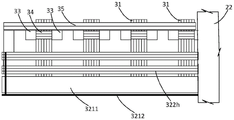
Fig. 3 is a side view of the reverse girder erection construction platform of the bridge girder erection machine facing one side of the ramp.
Fig. 4 is a side view of the reverse beam erection construction platform of the bridge girder erection machine facing to the side of the intercommunicating main line.
Fig. 5 is a sectional view a-a in fig. 3.
Fig. 6 is a top view of the reverse beam erection construction platform of the bridge girder erection machine of the utility model.
Fig. 7 is the cross-sectional view of the stop block and the supporting beam along the transverse bridge direction in the reverse bridge erecting construction platform of the bridge erecting machine of the utility model.
Fig. 8 is the cross-sectional view of the stop block and the supporting beam along the bridge direction in the reverse bridge girder erection construction platform of the bridge girder erection machine of the utility model.
Fig. 9 is the utility model discloses the structure sketch map of the T roof beam of reposition of redundant personnel tip department and the cast-in-place linkage segment of adjacent T roof beam construction.
Detailed Description
The invention will be further explained with reference to the drawings and the specific embodiments.
Referring to fig. 1, the utility model provides a reverse frame work platform of bridge girder erection machine for solve and normally advance the problem of construction at the reposition of redundant personnel tip widen of intercommunication thread and ramp and can't utilize the bridge girder erection machine. The utility model discloses a construction platform erects on the bent cap of reposition of redundant personnel tip department, provides safe and reliable's operation face for the bridging machine at the widening section, and the well landing leg of bridging machine is located on the T roof beam top surface that erects in the bridge inboard (intercommunication thread department promptly), and on the steel platform was located in the bridge outside (ramp department promptly), the T roof beam was erect in the sideslip about the bridging machine can normally. The following description is made of the reverse beam erecting construction platform of the bridge girder erection machine of the present invention with reference to the accompanying drawings.
Referring to fig. 1, a top view of the junction between the main line and the ramp of the bridge girder erection machine is shown. The structure of the reverse beam erecting construction platform of the bridge girder erection machine of the present invention will be described with reference to fig. 1.
As shown in fig. 1, the direction F in fig. 1 is a bridging direction, the construction sequence of the bridge is that the interconnecting main line 20a is constructed first, then the ramp 20b is constructed, and the interconnecting main line 20a is pushed in the reverse direction, so that the construction working surface of the bridging machine is widened from narrow to wide at the diversion end 201 constructed to the interconnecting main line 20a and the ramp 20 b. In the example shown in fig. 1, the construction of the bridge girder erection machine at the diversion end 201 goes through the interchange trunk 20a from the normal 5T-beams to the 9T-beams.
Referring to fig. 2, a bridge girder erection machine 10 is supported at the front part of a T-shaped beam 22, the bridge girder erection machine 10 includes a front leg 11, a middle leg 12 and a rear leg 13, the front leg 11 is slidably mounted on a front guide rail 14, the middle leg 12 is slidably mounted on a middle guide rail 15, the bridge girder erection machine 10 is supported on the front leg 11, the middle leg 12 and the rear leg 13, and a front traveling crown block 16 and a rear traveling crown block 17 are slidably mounted on the bridge girder erection machine 10. The front guide rail 14 is laid on the cover beam 23 at the front side of the currently hoisted T-beam 22, the front guide rail 14 is laid along the transverse bridge direction, the middle guide rail 14 is laid on the end part of the erected T-beam 22 adjacent to the currently hoisted T-beam 22, the middle guide rail 14 is not completely located on the cover beam 22 below the middle guide rail, and part of the middle guide rail is located on the outer side of the cover beam 22. The part of the bridge girder erection machine 10 between the middle guide rail 14 and the front guide rail 15 can slide along the middle guide rail 14 and the front guide rail 15 along with the front support leg 11 and the middle support leg 12, so as to complete the hoisting of the T-beam 22 of the corresponding part. The T-shaped beams 22 are located on the two adjacent bent cap beams 23, the two adjacent T-shaped beams 22 are connected together through cast-in-place connecting sections, the bent cap beams 23 are located on the corresponding pier columns 21 which are vertically arranged, and after the T-shaped beams 22 are erected, bridge construction at the positions is completed.
At the diversion end 201 of the main interconnection line 20a and the ramp 20b under construction, since the erected cover beam 23 is not located at the diversion end 201, the middle guide rail 14 cannot be seated at the diversion end 201, and further the bridge girder erection machine 10 cannot traverse to the diversion end 201, so that 4T-shaped beams which are excessive at the diversion end 201 cannot be erected by the bridge girder erection machine 10. In order to solve the problem, the utility model provides a reverse beam erection construction platform of bridge girder erection machine, as shown in fig. 3 to 5, the construction platform 30 is arranged at the shunting end 201 of the intercommunication mainline 20a and the ramp 20b, the construction platform 30 comprises a supporting beam 31 and a steel platform 32, the supporting beam 31 is laid on the cover beam 23 at the shunting end 201, the end of the supporting beam 31 protrudes out of the end of the corresponding cover beam 23 and forms an overhanging end 311; a steel platform 32 is placed on the support beam 31, the steel platform 32 is disposed on the support beam 31 on the side close to the ramp 20b, and one side of the steel platform 32 is placed on the corresponding overhanging end portion 311, the top surface of the steel platform 32 is flush with the top surface of the T-beam 22 on the interconnecting main line 20a, and the bridge girder 10 is supported by the top surface of the steel platform 32.
The end of the supporting beam 31 is formed into an overhanging end 311, so as to provide stable support for the steel platform 32, so that the supported position of the steel platform 32 corresponds to the arrangement position of the middle guide rail 15 of the middle supporting leg 12 of the bridge girder erection machine 10, so that the middle guide rail 15 can be laid on the steel platform 32, and then the middle supporting leg 12 can move to the diversion end 201, so as to use the bridge girder erection machine 10 to erect the T-beam 22 at the construction diversion end 201.
In one embodiment, as shown in fig. 4 and 6, the support beam 31 is spaced above the capping beam 23; the cover beam 23 is poured with the stoppers 33 positioned on the two opposite sides of the supporting beam 31, the embedded connecting pieces 34 are connected between the stoppers 33 positioned on the two opposite sides of the supporting beam 31 in a pulling and tying manner, and the bottoms of the embedded connecting pieces 34 are pressed on the supporting beam 31. The embedded connecting pieces 34 are partially embedded in the corresponding stoppers 33, and the embedded connecting pieces 34 are also arranged on the supporting beams 31 and used for pressing the supporting beams 31 to ensure the structural stability of the supporting beams 31 so as to provide firm and stable support for the steel platform 32. And the stoppers 33 are cast on two opposite sides of the support beam 31, so that the support beam 31 is clamped, the lateral displacement of the support beam 31 is avoided, and the structural stability of the support beam 31 is improved.
Preferably, the stoppers 33 are disposed on opposite sides of the capping beam 23, that is, the stoppers 33 are disposed near both overhanging ends of the supporting beam 31 to clamp both ends of the supporting beam 31, thereby improving structural stability of the supporting beam 31.
Further, as shown in fig. 7 and 8, when the bent cap 23 is constructed, the reinforcing bars of the stopper 33 are embedded in correspondence with the installation position of the stopper 33, and the bent cap 23 is roughened in correspondence with the position of the stopper 33 after the construction. Then place pre-buried connecting piece 34 on supporting beam 31, place the tip of pre-buried connecting piece 34 respectively in the pouring space of the dog 33 that corresponds and with the reinforcing bar fixed connection of dog 33, then prop up the template of establishing dog 33, pour and form dog 33 to bury partial pre-buried connecting piece 34 in the dog 33, this pre-buried connecting piece 34 can firmly buckle supporting beam 31. The stopper 33 is also connected with the cover beam 23 into a whole through a stopper steel bar, so that the structural strength is high, and a reliable clamping effect can be provided for the support beam 31. Preferably, the block 33 is formed by casting C50 concrete, and the casting should be performed with enhanced vibration, and the slump, the workability and the mixing time of the concrete should be strictly controlled, so as to ensure that the formed block 33 has high stress performance.
In one embodiment, as shown in fig. 5 and 6, a tie member 35 is disposed on the end of the support beam 31 away from the steel platform 32, and the tie member 35 is disposed on the support beam 31 and connected to the support beam 31. The drawknot piece 35 links together a plurality of supporting beams 31, and on the end of encorbelmenting of keeping away from steel platform 32 on supporting beam 31 was placed in to drawknot piece 35 to this drawknot piece 35 supported and leans on in the dog 33 that corresponds, drawknot piece 35 and the equal fixed connection of supporting beam 31 that corresponds, a plurality of supporting beams 31 drawknot that set up the interval through drawknot piece 35 link together, make supporting beam 31 connect into whole, improve supporting beam 31's overall stability.
Preferably, as shown in fig. 4, the support beams 31 are four rows, each row is composed of 6 h-beams, and the 6 h-beams are arranged side by side and welded and fixed to form an integral structure. The embedded connecting piece 34 is made of 6I-shaped steel and is pressed on the supporting beam 31. The tie member 35 is a channel steel to connect the four rows of support beams into a whole.
In one embodiment, as shown in fig. 3 and 5, an overhanging aisle portion 321 protruding outward is disposed on one side of the upper portion of the steel platform 32 corresponding to the ramp 20b, as shown in fig. 6, an aisle board 3211 is laid on the overhanging aisle portion 321, an aisle for people to walk is formed by the laid aisle boards 3211, and a protection fence 3212 is erected at an end of the overhanging aisle portion 321 to ensure the safety of the people operation. Preferably, a protection fence 321 is also provided at an end of the cap beam 23 and an end of the aisle panel 3211, and the protection fence 321 is fixedly connected with a protection fence 3212 provided at an end of the overhanging aisle portion 321.
In one embodiment, the steel platform 32 comprises a plurality of layers of steel members arranged in an overlapping arrangement.
As shown in fig. 3 to 5, the steel platform 32 includes a first layer of steel members 322a, the first layer of steel members 322a is laid on the support beams 31, and the laying direction of the first layer of steel members 322a is perpendicular to the laying direction of the support beams 31. Preferably, the first layer of steel members 322a are two I-beams of I63C I-beams, the distance is 100cm, and in order to prevent the I-beams from inclining, opposite-pulling screws are connected between the two I-beams in a pulling mode and are arranged at intervals. The outer one of the two i-beams is located on the overhanging end 311 of the support beam 31, and the overhanging end 311 of the support beam 31 can provide stable support for the first-layer steel member 322a due to the high stability of the support beam 31, and although the overhanging end 311 is pressed by the steel platform 32, the first-layer steel member 322a has high stability due to the pre-embedded connecting piece 34 pressing the support beam 31.
Further, the steel platform 32 further includes a second layer of steel members 322b, the second layer of steel members 322b is laid on the first layer of steel members 322a, and the laying direction of the second layer of steel members 322b is perpendicular to the laying direction of the first layer of steel members 322 a. Preferably, the second layer of steel members 322b is I20B I-steel, spaced 50cm apart.
The steel platform 32 further comprises a third layer of steel members 322c, wherein the third layer of steel members 322c is laid on the second layer of steel members 322b, and the laying direction of the third layer of steel members 322c is perpendicular to the laying direction of the second layer of steel members 322 b. Preferably, two I-shaped steels I63C are adopted as the third-layer steel member 322c, the distance is 90cm, and in order to prevent the I-shaped steels from inclining, opposite-pulling screws are connected between the two I-shaped steels in a pulling mode and are arranged at intervals. As shown in fig. 3, in order to apply a good force to the upper layer of the steel member, one of the two I-beams located at the outer side is moved inward, and a stay 3221c is provided at the outer side of the I-beam, and I20B I-beam is used as the stay 3221 c.
The steel platform 32 further includes a fourth layer of steel members 322d, ends of the fourth layer of steel members 322d are cantilevered outward to form an overhanging passage portion 321, the fourth layer of steel members 322d are laid on the third layer of steel members 322c, and a laying direction of the fourth layer of steel members 322d is perpendicular to a laying direction of the third layer of steel members 322 c. Preferably, the fourth layer of steel members 322d is I20B I-beams, the distance between the I-beams is 50cm, the outer overhang is 80cm, and square steel is fully paved on the overhang aisle portion 321 to form an aisle.
The steel platform 32 further comprises a fifth layer of steel members 322e, a sixth layer of steel members 322f, a seventh layer of steel members 322g and an eighth layer of steel members 322h which are staggered transversely and longitudinally, wherein the fifth layer of steel members 322e and the seventh layer of steel members 322g adopt two rows of abutted I-shaped steel, each row has 3 trusses, and the distance between the rows and the center is 100 m. The sixth layer of steel members adopts I20B I-steel, the transverse distance is 50cm, and the vertical direction corresponds to the second layer of steel members 322b and the fourth layer of steel members 322 d. Eighth layer steel member 322h is the steel sheet and the square timber of adjustable roughness to make this eighth layer steel member 322 h's top surface and the top surface parallel and level of adjacent T roof beam 22.
When the steel platform 32 is constructed, in order to ensure that the whole steel platform support is stable, the lap joints between the I-beams are welded firmly, two I-beams are required to be butted and leveled before the I-beams are welded, and the I-beams are welded after being aligned vertically and horizontally so as to avoid quality problems of welded joints, later stress deformation and influence on the safety and stability of the whole platform.
Once the steel platform 32 is erected, the center rail 14 may be laid over the steel platform 32 so that the bridge girder erection machine 10 may be moved to the diversion end 201 for construction. Before the bridge girder erection machine 10 moves, all safety test run checks are performed. And (3) longitudinally moving the bridge erecting machine line to the right position, placing the front and middle support leg steel guide beams according to the width required by the T beam at the widening section, hoisting the front steel guide beam by a chain block matched with a jack, supporting a pad by a square wood frame on the top of the capping beam, tightly connecting the square wood in the wood frame by a stud to flatten the square wood, then loosening the middle wood support and the hand block, and leveling the bridge erecting machine by the jack. And a square wood support pad is matched with a chain block to transversely move the middle guide beam to the steel platform to be in place, and the square wood and the steel plate level the steel guide rail. The bridge girder erection machine moves in place, stable reinforcement measures are taken, steel wire ropes are adopted to match with chain blocks to tie the whole row of steel bars of the middle guide beam and the transverse partition plate in gaps of the transverse partition plate, and then the wheels of the guide beam flat car are wedged tightly. In order to improve the firm connection between the T beam at the shunting end part and the T beam at the intercommunicating main line, the anchoring main rib 24 is arranged at the early casting section, and the anchoring main rib 24 is utilized to improve the structural strength of the cast-in-place connecting section, so that the connecting strength between the T beams is improved.
The bridge erecting machine needs to carry out no-load test running inspection, particularly, the rail laying condition is inspected before transverse running. The installation of the beam pieces can be carried out only after the bridge girder erection machine operates normally. The beam is conveyed to the beam feeding position between two main beams of the bridge girder erection machine, a self-propelled beam conveying flat car beam feeding is adopted, the front crown block is started to the T beam hoisting point position, and the hoisting point position is arranged near the support. And starting the front crown block to move forwards, and simultaneously starting the beam-transporting trolley to keep synchronization, so that the trolley and the front crown block hoist the T beam to move forwards slowly. And when the second lifting point of the beam piece moves to the position of the rear crown block, stopping the operation, tying a steel wire rope of the second lifting point, starting the rear crown block, and lifting the beam 10cm away from the beam-conveying trolley. A limiting device is required to be arranged before the crown block walks to control the running range of the crown block, the height of a lifting beam is determined according to the running line condition in the lifting beam and running process, and the beam body is kept horizontal. And after the lifting beam reaches the designed position, the transverse track is checked again, the front and middle support leg walking trolleys are opened after the situation that no errors exist is confirmed, the running speed of the trolleys is kept synchronous, and the bridge girder erection machine is transversely moved to enable the to-be-erected beam to be located right above the designed position. And simultaneously starting the two hoisting beam crown blocks and slowly dropping the beams. When the beam is 2-3cm away from the temporary support, one overhead traveling crane is closed, the other overhead traveling crane is opened, one end of the beam is firstly dropped on the support, and then the other overhead traveling crane is started, so that the other end of the beam is dropped on the support. And (5) checking the contact condition of the T beam and the support, wherein the T beam and the temporary support are required to be in tight contact. After the T beam is erected, temporary supports are immediately arranged at two ends, so that the T beam keeps vertical and stable temporary supports, and the T beam is prevented from inclining and overturning. When two or more than two T-shaped beams are erected, the cross beams and the wet joint reinforcing steel bars of the top plate are immediately connected to connect the erected T-shaped beams into a whole, so that the stability is enhanced, and the T-shaped beams are prevented from overturning.
And after the beam piece is installed, the bridge girder erection machine is moved away, and after the next span hole is completed, the steel platform support can be dismantled, a forbidden area fence and a warning mark are arranged around the operation area, and a specially-assigned person is dispatched to perform peripheral warning work. The platform support is dismantled from top to bottom, surface layers of auxiliary structure square timbers and square steels are sequentially arranged, then I-steel distribution beams are arranged on the lower layers, the dismantling method is basically opposite to the building method, and materials are conveyed by a crane matched with a worker.
When the T-shaped beam is erected, a cushion stone is arranged between the oppositely arranged stop blocks constructed on the bent cap, the bottom of the T-shaped beam is arranged on the cushion stone, and the T-shaped beam is clamped through the two stop blocks.
The utility model discloses a construction problem is erect by narrow widen precast beam piece to the reposition of redundant personnel tip of thread and ramp under the construction conditions that bridge girder erection machine reverse frame girder construction platform solved intercommunication bridge geographical position and the short ramp cast-in-place roof beam of time pouring under the construction period, has avoided the beam piece to erect and is hindered, guarantees that the beam piece is prefabricated and erects harmoniously unified, and firm each item construction work that impels effectively guarantees construction period. The process is scientific and reasonable, the construction process is safe, reliable, high in quality and quick, a new way is provided for similar engineering construction, and the method has a great popularization value.
The utility model discloses a steel platform is all set up by the I-steel, and bearing capacity is high, and is simple and easy feasible, and is safe high-efficient. The steel platform can recycle the I-steel supported by the bent cap bottom die, so that the construction cost is effectively reduced.
The ramp is a multi-span cast-in-place box girder, the cast-in-place box girder has long construction time and short construction period, the main line can not wait for the T girder erection at the shunting end part of the main line and the ramp after the construction of the two ramps is finished, the steel platform construction is simple, the support erection speed is high, and the construction is greatly shortened.
The weight of the 30mT beam is about 83t, at least more than 100t of cranes are needed for hoisting by two cranes, and the crane cost is high. Normal bridge floor headroom width only has 11m, and the width is not enough, and the crane landing leg extends not to open, and the danger coefficient is big, and crane hoist and mount 30mT roof beam need the swing arm great, and the hoist and mount process control degree of difficulty is big, can't counterpoint correctly.
The supporting leg transverse guide rail in the double-guide-beam bridge girder erection machine is directly located on the steel platform, the bridge girder erection machine can automatically move transversely left and right, the beams are accurately aligned and dropped, and the requirement of controlling the working medium quantity of a T-beam bridge girder installation is met.
The present invention has been described in detail with reference to the embodiments shown in the drawings, and those skilled in the art can make various modifications to the present invention based on the above description. Therefore, certain details of the embodiments should not be construed as limitations of the invention, which are intended to be covered by the following claims.
Claims (5)
1. The utility model provides a reverse frame roof beam construction platform of bridge girder erection machine, locates the reposition of redundant personnel tip department of intercommunication thread and ramp, its characterized in that, construction platform includes:
the supporting beams are laid on the cover beams at the diversion end parts, and the end parts of the supporting beams protrude out of the end parts of the corresponding cover beams to form overhanging end parts; and
and the steel platform is arranged on one side, close to the ramp, of the supporting beam, one side of the steel platform is arranged on the corresponding overhanging end part, the top surface of the steel platform is flush with the top surface of the T beam on the intercommunication main line, and a support foundation is provided for the bridge girder erection machine through the top surface of the steel platform.
2. The reverse beam erection construction platform of claim 1, wherein said support beam is spaced above said capping beam;
the cover beam is provided with a plurality of stop blocks, the stop blocks are arranged on two opposite sides of the supporting beam in a pouring mode, the stop blocks arranged on the two opposite sides of the supporting beam are connected with embedded connecting pieces in a pulling mode, and the bottoms of the embedded connecting pieces are arranged on the supporting beam in a pressing mode.
3. The reverse beam erection construction platform of claim 1 or 2, wherein a tie member is provided at an end of the support beam away from the steel platform, and the tie member is disposed on the support beam and is connected and fixed with the support beam.
4. The reverse beam erecting construction platform of the bridge girder erection machine as claimed in claim 1, wherein an overhanging aisle portion protruding outwards is provided at one side of the upper portion of the steel platform corresponding to the ramp, a crossing plate is laid on the overhanging aisle portion, and a protection fence is erected at an end of the overhanging aisle portion.
5. The reverse beam construction platform of the bridge girder erection machine as claimed in claim 1, wherein the steel platform comprises a plurality of layers of steel members arranged in an overlapping manner.
Priority Applications (1)
| Application Number | Priority Date | Filing Date | Title |
|---|---|---|---|
| CN201921643160.2U CN211171638U (en) | 2019-09-29 | 2019-09-29 | Reverse beam erecting construction platform of bridge girder erection machine |
Applications Claiming Priority (1)
| Application Number | Priority Date | Filing Date | Title |
|---|---|---|---|
| CN201921643160.2U CN211171638U (en) | 2019-09-29 | 2019-09-29 | Reverse beam erecting construction platform of bridge girder erection machine |
Publications (1)
| Publication Number | Publication Date |
|---|---|
| CN211171638U true CN211171638U (en) | 2020-08-04 |
Family
ID=71796259
Family Applications (1)
| Application Number | Title | Priority Date | Filing Date |
|---|---|---|---|
| CN201921643160.2U Active CN211171638U (en) | 2019-09-29 | 2019-09-29 | Reverse beam erecting construction platform of bridge girder erection machine |
Country Status (1)
| Country | Link |
|---|---|
| CN (1) | CN211171638U (en) |
Cited By (1)
| Publication number | Priority date | Publication date | Assignee | Title |
|---|---|---|---|---|
| CN110552294A (en) * | 2019-09-29 | 2019-12-10 | 中国建筑第八工程局有限公司 | Bridge girder erection machine reverse beam erection construction platform and construction method thereof |
-
2019
- 2019-09-29 CN CN201921643160.2U patent/CN211171638U/en active Active
Cited By (2)
| Publication number | Priority date | Publication date | Assignee | Title |
|---|---|---|---|---|
| CN110552294A (en) * | 2019-09-29 | 2019-12-10 | 中国建筑第八工程局有限公司 | Bridge girder erection machine reverse beam erection construction platform and construction method thereof |
| CN110552294B (en) * | 2019-09-29 | 2024-06-14 | 中国建筑第八工程局有限公司 | Reverse girder erection construction platform of bridge girder erection machine and construction method thereof |
Similar Documents
| Publication | Publication Date | Title |
|---|---|---|
| CN108532465B (en) | A kind of construction method of the main bridge of Through Steel case arch bridge | |
| CN101586330B (en) | Receding construction method of cradle of continuous girder bridge made of prestressing concrete | |
| CN104790295B (en) | Construction method of tire type gantry crane frame beam | |
| CN110820573B (en) | Construction method of steel-concrete composite beam of high-pier long-span bridge in mountainous area | |
| CN108729354B (en) | Downstream bridge movable formwork and construction method thereof | |
| CN110230261B (en) | Mounting construction method for upper frame beam of double-layer synchronous beam | |
| CN107013038A (en) | A kind of steel structure slipping of building roof lighting Zhongting changes column construction method | |
| CN110847062A (en) | Construction method for whole-hole assembly double-width erection in 80-meter-span wide steel box girder factory | |
| CN111254836A (en) | Site assembling and bridge girder erection machine erecting construction method for large-span steel-concrete composite beam in mountainous area | |
| CN110344334B (en) | Construction method for two-span continuous steel-concrete composite bridge by adopting back cable type bridge girder erection machine | |
| CN112575694A (en) | Mounting construction method for long-span T beam | |
| CN113957793A (en) | Construction method for prefabricating box girder support in complex urban environment | |
| CN110552294B (en) | Reverse girder erection construction platform of bridge girder erection machine and construction method thereof | |
| CN111778857B (en) | Process for synchronously erecting upper and lower beams of double-layer overhead bridge of urban public rail | |
| JPH0841826A (en) | Bridge construction method, bridge construction equipment and main girder unit | |
| CN108625270A (en) | Nose girder gantry crane installs bridge prefabrication box girder construction method | |
| CN211171638U (en) | Reverse beam erecting construction platform of bridge girder erection machine | |
| CN102659027B (en) | Variable-span transit method for girder-erecting gantry crane | |
| CN207987749U (en) | Ride cable-styled erection crane | |
| CN211973152U (en) | Large-tonnage box girder erection construction system capable of realizing height control | |
| CN209338005U (en) | A kind of mobile height leg gantry crane of erecting beam construction | |
| CN111705682A (en) | A construction method and equipment for demolition and reconstruction of superstructure of widened bridge across electrified railway | |
| CN208328660U (en) | The U-shaped girder construction of the Two bors d's oeuveres of combined bridge | |
| CN113481768B (en) | Method for adding railway line to existing wharf trestle | |
| CN116949946A (en) | Construction method for bridge bridging of small-radius curve bridge |
Legal Events
| Date | Code | Title | Description |
|---|---|---|---|
| GR01 | Patent grant | ||
| GR01 | Patent grant |