CN112351867A - Robotized construction system - Google Patents
Robotized construction system Download PDFInfo
- Publication number
- CN112351867A CN112351867A CN201980039421.6A CN201980039421A CN112351867A CN 112351867 A CN112351867 A CN 112351867A CN 201980039421 A CN201980039421 A CN 201980039421A CN 112351867 A CN112351867 A CN 112351867A
- Authority
- CN
- China
- Prior art keywords
- building system
- robotic
- building
- nozzles
- robot
- Prior art date
- Legal status (The legal status is an assumption and is not a legal conclusion. Google has not performed a legal analysis and makes no representation as to the accuracy of the status listed.)
- Pending
Links
- 238000010276 construction Methods 0.000 title claims description 16
- 238000004519 manufacturing process Methods 0.000 claims abstract description 36
- 239000000463 material Substances 0.000 claims abstract description 35
- 239000004566 building material Substances 0.000 claims abstract description 24
- 239000012530 fluid Substances 0.000 claims description 15
- 239000000853 adhesive Substances 0.000 claims description 8
- 230000001070 adhesive effect Effects 0.000 claims description 8
- 238000005498 polishing Methods 0.000 claims description 7
- 238000000151 deposition Methods 0.000 claims description 4
- 239000007787 solid Substances 0.000 claims description 4
- 238000007639 printing Methods 0.000 claims description 3
- 238000005056 compaction Methods 0.000 claims description 2
- 239000004568 cement Substances 0.000 abstract description 4
- 239000007788 liquid Substances 0.000 abstract description 3
- 230000003750 conditioning effect Effects 0.000 description 5
- 238000000576 coating method Methods 0.000 description 4
- 238000005266 casting Methods 0.000 description 3
- 238000000465 moulding Methods 0.000 description 3
- 230000007704 transition Effects 0.000 description 3
- XLYOFNOQVPJJNP-UHFFFAOYSA-N water Substances O XLYOFNOQVPJJNP-UHFFFAOYSA-N 0.000 description 3
- 230000001174 ascending effect Effects 0.000 description 2
- 238000005452 bending Methods 0.000 description 2
- 239000011248 coating agent Substances 0.000 description 2
- 239000004567 concrete Substances 0.000 description 2
- 239000004035 construction material Substances 0.000 description 2
- 230000008021 deposition Effects 0.000 description 2
- 238000001125 extrusion Methods 0.000 description 2
- 239000011178 precast concrete Substances 0.000 description 2
- 230000001360 synchronised effect Effects 0.000 description 2
- 238000005524 ceramic coating Methods 0.000 description 1
- 238000006073 displacement reaction Methods 0.000 description 1
- 230000000694 effects Effects 0.000 description 1
- 230000006698 induction Effects 0.000 description 1
- 238000002347 injection Methods 0.000 description 1
- 239000007924 injection Substances 0.000 description 1
- 239000011810 insulating material Substances 0.000 description 1
- 238000009413 insulation Methods 0.000 description 1
- 230000002452 interceptive effect Effects 0.000 description 1
- 239000002184 metal Substances 0.000 description 1
- 238000000034 method Methods 0.000 description 1
- 239000004570 mortar (masonry) Substances 0.000 description 1
- 238000005086 pumping Methods 0.000 description 1
- 239000011343 solid material Substances 0.000 description 1
- 238000007711 solidification Methods 0.000 description 1
- 230000008023 solidification Effects 0.000 description 1
- 239000000725 suspension Substances 0.000 description 1
Images


Classifications
-
- E—FIXED CONSTRUCTIONS
- E04—BUILDING
- E04B—GENERAL BUILDING CONSTRUCTIONS; WALLS, e.g. PARTITIONS; ROOFS; FLOORS; CEILINGS; INSULATION OR OTHER PROTECTION OF BUILDINGS
- E04B1/00—Constructions in general; Structures which are not restricted either to walls, e.g. partitions, or floors or ceilings or roofs
- E04B1/35—Extraordinary methods of construction, e.g. lift-slab, jack-block
- E04B1/3505—Extraordinary methods of construction, e.g. lift-slab, jack-block characterised by the in situ moulding of large parts of a structure
-
- B—PERFORMING OPERATIONS; TRANSPORTING
- B05—SPRAYING OR ATOMISING IN GENERAL; APPLYING FLUENT MATERIALS TO SURFACES, IN GENERAL
- B05B—SPRAYING APPARATUS; ATOMISING APPARATUS; NOZZLES
- B05B13/00—Machines or plants for applying liquids or other fluent materials to surfaces of objects or other work by spraying, not covered by groups B05B1/00 - B05B11/00
- B05B13/02—Means for supporting work; Arrangement or mounting of spray heads; Adaptation or arrangement of means for feeding work
- B05B13/04—Means for supporting work; Arrangement or mounting of spray heads; Adaptation or arrangement of means for feeding work the spray heads being moved during spraying operation
- B05B13/0405—Means for supporting work; Arrangement or mounting of spray heads; Adaptation or arrangement of means for feeding work the spray heads being moved during spraying operation with reciprocating or oscillating spray heads
- B05B13/041—Means for supporting work; Arrangement or mounting of spray heads; Adaptation or arrangement of means for feeding work the spray heads being moved during spraying operation with reciprocating or oscillating spray heads with spray heads reciprocating along a straight line
-
- B—PERFORMING OPERATIONS; TRANSPORTING
- B05—SPRAYING OR ATOMISING IN GENERAL; APPLYING FLUENT MATERIALS TO SURFACES, IN GENERAL
- B05B—SPRAYING APPARATUS; ATOMISING APPARATUS; NOZZLES
- B05B13/00—Machines or plants for applying liquids or other fluent materials to surfaces of objects or other work by spraying, not covered by groups B05B1/00 - B05B11/00
- B05B13/02—Means for supporting work; Arrangement or mounting of spray heads; Adaptation or arrangement of means for feeding work
- B05B13/04—Means for supporting work; Arrangement or mounting of spray heads; Adaptation or arrangement of means for feeding work the spray heads being moved during spraying operation
- B05B13/0431—Means for supporting work; Arrangement or mounting of spray heads; Adaptation or arrangement of means for feeding work the spray heads being moved during spraying operation with spray heads moved by robots or articulated arms, e.g. for applying liquid or other fluent material to 3D-surfaces
-
- B—PERFORMING OPERATIONS; TRANSPORTING
- B25—HAND TOOLS; PORTABLE POWER-DRIVEN TOOLS; MANIPULATORS
- B25J—MANIPULATORS; CHAMBERS PROVIDED WITH MANIPULATION DEVICES
- B25J11/00—Manipulators not otherwise provided for
- B25J11/0075—Manipulators for painting or coating
-
- B—PERFORMING OPERATIONS; TRANSPORTING
- B25—HAND TOOLS; PORTABLE POWER-DRIVEN TOOLS; MANIPULATORS
- B25J—MANIPULATORS; CHAMBERS PROVIDED WITH MANIPULATION DEVICES
- B25J9/00—Programme-controlled manipulators
- B25J9/02—Programme-controlled manipulators characterised by movement of the arms, e.g. cartesian coordinate type
- B25J9/023—Cartesian coordinate type
- B25J9/026—Gantry-type
-
- B—PERFORMING OPERATIONS; TRANSPORTING
- B28—WORKING CEMENT, CLAY, OR STONE
- B28B—SHAPING CLAY OR OTHER CERAMIC COMPOSITIONS; SHAPING SLAG; SHAPING MIXTURES CONTAINING CEMENTITIOUS MATERIAL, e.g. PLASTER
- B28B1/00—Producing shaped prefabricated articles from the material
-
- B—PERFORMING OPERATIONS; TRANSPORTING
- B28—WORKING CEMENT, CLAY, OR STONE
- B28B—SHAPING CLAY OR OTHER CERAMIC COMPOSITIONS; SHAPING SLAG; SHAPING MIXTURES CONTAINING CEMENTITIOUS MATERIAL, e.g. PLASTER
- B28B1/00—Producing shaped prefabricated articles from the material
- B28B1/001—Rapid manufacturing of 3D objects by additive depositing, agglomerating or laminating of material
-
- B—PERFORMING OPERATIONS; TRANSPORTING
- B28—WORKING CEMENT, CLAY, OR STONE
- B28B—SHAPING CLAY OR OTHER CERAMIC COMPOSITIONS; SHAPING SLAG; SHAPING MIXTURES CONTAINING CEMENTITIOUS MATERIAL, e.g. PLASTER
- B28B11/00—Apparatus or processes for treating or working the shaped or preshaped articles
- B28B11/08—Apparatus or processes for treating or working the shaped or preshaped articles for reshaping the surface, e.g. smoothing, roughening, corrugating, making screw-threads
- B28B11/0845—Apparatus or processes for treating or working the shaped or preshaped articles for reshaping the surface, e.g. smoothing, roughening, corrugating, making screw-threads for smoothing
-
- B—PERFORMING OPERATIONS; TRANSPORTING
- B29—WORKING OF PLASTICS; WORKING OF SUBSTANCES IN A PLASTIC STATE IN GENERAL
- B29C—SHAPING OR JOINING OF PLASTICS; SHAPING OF MATERIAL IN A PLASTIC STATE, NOT OTHERWISE PROVIDED FOR; AFTER-TREATMENT OF THE SHAPED PRODUCTS, e.g. REPAIRING
- B29C64/00—Additive manufacturing, i.e. manufacturing of three-dimensional [3D] objects by additive deposition, additive agglomeration or additive layering, e.g. by 3D printing, stereolithography or selective laser sintering
- B29C64/10—Processes of additive manufacturing
- B29C64/106—Processes of additive manufacturing using only liquids or viscous materials, e.g. depositing a continuous bead of viscous material
-
- B—PERFORMING OPERATIONS; TRANSPORTING
- B29—WORKING OF PLASTICS; WORKING OF SUBSTANCES IN A PLASTIC STATE IN GENERAL
- B29C—SHAPING OR JOINING OF PLASTICS; SHAPING OF MATERIAL IN A PLASTIC STATE, NOT OTHERWISE PROVIDED FOR; AFTER-TREATMENT OF THE SHAPED PRODUCTS, e.g. REPAIRING
- B29C64/00—Additive manufacturing, i.e. manufacturing of three-dimensional [3D] objects by additive deposition, additive agglomeration or additive layering, e.g. by 3D printing, stereolithography or selective laser sintering
- B29C64/20—Apparatus for additive manufacturing; Details thereof or accessories therefor
- B29C64/227—Driving means
-
- B—PERFORMING OPERATIONS; TRANSPORTING
- B33—ADDITIVE MANUFACTURING TECHNOLOGY
- B33Y—ADDITIVE MANUFACTURING, i.e. MANUFACTURING OF THREE-DIMENSIONAL [3-D] OBJECTS BY ADDITIVE DEPOSITION, ADDITIVE AGGLOMERATION OR ADDITIVE LAYERING, e.g. BY 3-D PRINTING, STEREOLITHOGRAPHY OR SELECTIVE LASER SINTERING
- B33Y10/00—Processes of additive manufacturing
-
- B—PERFORMING OPERATIONS; TRANSPORTING
- B33—ADDITIVE MANUFACTURING TECHNOLOGY
- B33Y—ADDITIVE MANUFACTURING, i.e. MANUFACTURING OF THREE-DIMENSIONAL [3-D] OBJECTS BY ADDITIVE DEPOSITION, ADDITIVE AGGLOMERATION OR ADDITIVE LAYERING, e.g. BY 3-D PRINTING, STEREOLITHOGRAPHY OR SELECTIVE LASER SINTERING
- B33Y30/00—Apparatus for additive manufacturing; Details thereof or accessories therefor
-
- B—PERFORMING OPERATIONS; TRANSPORTING
- B33—ADDITIVE MANUFACTURING TECHNOLOGY
- B33Y—ADDITIVE MANUFACTURING, i.e. MANUFACTURING OF THREE-DIMENSIONAL [3-D] OBJECTS BY ADDITIVE DEPOSITION, ADDITIVE AGGLOMERATION OR ADDITIVE LAYERING, e.g. BY 3-D PRINTING, STEREOLITHOGRAPHY OR SELECTIVE LASER SINTERING
- B33Y80/00—Products made by additive manufacturing
-
- E—FIXED CONSTRUCTIONS
- E04—BUILDING
- E04B—GENERAL BUILDING CONSTRUCTIONS; WALLS, e.g. PARTITIONS; ROOFS; FLOORS; CEILINGS; INSULATION OR OTHER PROTECTION OF BUILDINGS
- E04B1/00—Constructions in general; Structures which are not restricted either to walls, e.g. partitions, or floors or ceilings or roofs
- E04B1/16—Structures made from masses, e.g. of concrete, cast or similarly formed in situ with or without making use of additional elements, such as permanent forms, substructures to be coated with load-bearing material
-
- E—FIXED CONSTRUCTIONS
- E04—BUILDING
- E04B—GENERAL BUILDING CONSTRUCTIONS; WALLS, e.g. PARTITIONS; ROOFS; FLOORS; CEILINGS; INSULATION OR OTHER PROTECTION OF BUILDINGS
- E04B1/00—Constructions in general; Structures which are not restricted either to walls, e.g. partitions, or floors or ceilings or roofs
- E04B1/35—Extraordinary methods of construction, e.g. lift-slab, jack-block
-
- E—FIXED CONSTRUCTIONS
- E04—BUILDING
- E04F—FINISHING WORK ON BUILDINGS, e.g. STAIRS, FLOORS
- E04F21/00—Implements for finishing work on buildings
- E04F21/02—Implements for finishing work on buildings for applying plasticised masses to surfaces, e.g. plastering walls
- E04F21/06—Implements for applying plaster, insulating material, or the like
- E04F21/08—Mechanical implements
-
- E—FIXED CONSTRUCTIONS
- E04—BUILDING
- E04G—SCAFFOLDING; FORMS; SHUTTERING; BUILDING IMPLEMENTS OR AIDS, OR THEIR USE; HANDLING BUILDING MATERIALS ON THE SITE; REPAIRING, BREAKING-UP OR OTHER WORK ON EXISTING BUILDINGS
- E04G21/00—Preparing, conveying, or working-up building materials or building elements in situ; Other devices or measures for constructional work
- E04G21/02—Conveying or working-up concrete or similar masses able to be heaped or cast
- E04G21/04—Devices for both conveying and distributing
- E04G21/0418—Devices for both conveying and distributing with distribution hose
- E04G21/0427—Devices for both conveying and distributing with distribution hose on a static support, e.g. crane
-
- E—FIXED CONSTRUCTIONS
- E04—BUILDING
- E04G—SCAFFOLDING; FORMS; SHUTTERING; BUILDING IMPLEMENTS OR AIDS, OR THEIR USE; HANDLING BUILDING MATERIALS ON THE SITE; REPAIRING, BREAKING-UP OR OTHER WORK ON EXISTING BUILDINGS
- E04G21/00—Preparing, conveying, or working-up building materials or building elements in situ; Other devices or measures for constructional work
- E04G21/02—Conveying or working-up concrete or similar masses able to be heaped or cast
- E04G21/04—Devices for both conveying and distributing
- E04G21/0418—Devices for both conveying and distributing with distribution hose
- E04G21/0445—Devices for both conveying and distributing with distribution hose with booms
- E04G21/0463—Devices for both conveying and distributing with distribution hose with booms with boom control mechanisms, e.g. to automate concrete distribution
Landscapes
- Engineering & Computer Science (AREA)
- Architecture (AREA)
- Mechanical Engineering (AREA)
- Chemical & Material Sciences (AREA)
- Materials Engineering (AREA)
- Structural Engineering (AREA)
- Manufacturing & Machinery (AREA)
- Civil Engineering (AREA)
- Physics & Mathematics (AREA)
- Robotics (AREA)
- Ceramic Engineering (AREA)
- Optics & Photonics (AREA)
- Electromagnetism (AREA)
- Manipulator (AREA)
- Spray Control Apparatus (AREA)
- Conveying And Assembling Of Building Elements In Situ (AREA)
- Producing Shaped Articles From Materials (AREA)
- Devices For Post-Treatments, Processing, Supply, Discharge, And Other Processes (AREA)
- On-Site Construction Work That Accompanies The Preparation And Application Of Concrete (AREA)
Abstract
The present invention relates to a robot building system comprising a cartesian robot. The cartesian robot can be automatically raised as the height of the building increases. The robot building system comprises a robot system for supplying materials and electrical and electronic equipment and has a specific production tool. Some of these tools work by providing a layer of liquid building material, such as a cement-based material that hardens once deposited. While other tools work by forming and placing the building elements in determined positions.
Description
Technical Field
The object of the present invention is a system that allows erecting any monument, such as in particular a building, a structure, an infrastructure, by means of a cartesian robot with a robotic supply of liquid construction materials that, when solidified, form the vertical and horizontal elements of the monument, and the necessary electrical and electronic equipment to move the robot. As a noteworthy feature of the invention, it is possible for the cartesian robot to rise autonomously, fastening on the vertical surface of a structure, without the need for external lifting elements such as cranes.
Background
Construction is an activity with a strong demand on the workforce, which means that it is an area with insufficient productivity and a high risk of work accidents, which result from the manual nature of the many jobs performed. However, machines play a very important role, being essential in most tasks and in the safety aspects of performing them.
Among the machines used, it is noted that they are used for lifting materials, for levelling, for preparing and pouring mortars and concretes.
Another element that increases construction productivity is prefabricated construction materials, such as precast concrete elements and panels. Precast concrete elements include many products made at the factory by moulding and setting, such as large structural precast elements (such as beams, walls and columns), small structural precast elements (such as joists, concrete cylinders, blocks, curbs, paving stones), and special precast elements (among which are sleepers, columns and cabins). Until now, however, no system has been developed that drastically reduces human involvement in the construction task, or at least the applicant has appreciated that such a system has not been developed.
The present disclosure announces an automated system that allows the erection of almost any type of structure as the monuments get higher and higher, by using cartesian robots that autonomously rise above the monuments, and by the contribution of liquid building materials.
Disclosure of Invention
A robotized construction system, object of the present invention, comprises:
a cartesian robot, in turn comprising:
two horizontal beams, such that at least part of the storey of the monument is located between said beams;
one or more bridges arranged between the horizontal beams and designed to move along said horizontal beams;
one or more trolleys arranged on each of said bridges and designed to move along said bridge;
one or more telescopic columns, each coupled to one of the trolleys;
one or more cantilevers, each of said cantilevers having one or more degrees of freedom and being coupled to a free end of a column;
a plurality of actuators that move the bridge, trolley, cantilever and extend or retract the telescopic column;
a plurality of position sensors of the bridge, the trolley and the cantilever;
a programmable controller that controls at least the actuator and receives data from at least the position sensor;
one or more manufacturing tools for vertical and horizontal elements arranged on the cantilever, the vertical and horizontal elements forming part of a building or other type of monument;
a power and electronic supply means driven by the controller;
means to supply one or more fluid building materials, water and pressurized air simultaneously to the manufacturing tool.
Drawings
Figure 1 shows a perspective view of a cartesian robot.
Figure 2 shows a perspective view of the cartesian robot when a floor of the building has been constructed and the lifting device is anchored to the ceiling of the floor.
Figure 3 shows a perspective view of a cartesian robot ascending above a floor that has been built.
Figure 4 shows a perspective view of a four-storey building and a cartesian robot anchored to the ceiling of the third storey.
Fig. 5 shows a perspective view of a detail of the cartesian robot ready to start ascending.
Figure 6 shows a perspective view of a detail of the cartesian robot fully raised to build a new floor.
Fig. 7 shows a perspective view of a detail of the rack-and-pinion type lifting device.
Figure 8 shows a perspective view of a cartesian robot with two bridges.
Figure 9 shows a perspective view of a cartesian robot with two bridges and two carts on each bridge.
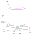
Figure 10 shows a perspective view of the entire robotic supply system of the invention for materials and conduits for power and electronic cables.
Fig. 11 shows a view of a robot rotating drum used in a robot supply system, in which the pipe is coiled in a spiral form.
Fig. 12 shows a view of the curved and powered device and the support of the swivel bearing through which the pipe is guided.
Figure 13 shows a perspective view of a nozzle with a square cross section and an example of a vertical element in the process of construction.
Fig. 14 shows a perspective view of a manufacturing tool with 5 nozzles and a built vertical element, where one nozzle is movable.
Fig. 15 shows a perspective view of a manufacturing tool with a mold disposed on the free end of the nozzle.
Fig. 16 shows a perspective view of a vertical element built by means of an element made by means of the mould of fig. 15.
Figure 17 shows a perspective view of the mould with the lower surface of the mould open and storing the solid building elements.
Fig. 18 shows a perspective view of a manufacturing tool working by moulding and vacuum.
Fig. 19 shows an exploded perspective view of a manufacturing tool for depositing layers in the form of a printing roll.
Fig. 20 shows a perspective view of the tool of fig. 19 forming a construction element such as a wall.
Fig. 21 shows a perspective view of a leveling tool for a level surface.
Fig. 22 shows two perspective views of a leveling tool for a vertical surface.
Fig. 23 shows two perspective views of an adhesive extrusion tool and a processor.
Figure 24 shows a perspective view of a conditioning and polishing disk manufacturing tool.
Figure 25 shows an exploded perspective view of a conditioning and polishing disk manufacturing tool.
Detailed Description
The robotic building system comprises a cartesian robot (1), one or more manufacturing tools (3), a power supply (4) and a building material supply (5).
The cartesian robot comprises two beams (8), occasionally supplemented by columns (7) forming a column corridor (6), in fig. 1, 8 and 9 the preferred embodiment is shown with four columns and horizontal beams (8), wherein the beams are telescopic to fit monuments of different lengths. One or more bridges (9) may also be telescopic to vary their width in case the beams (8) are not parallel to each other, one or more bridges (9) being arranged between the horizontal beams (8) and one or more trolleys (10) being arranged on them. In fig. 1, only one bridge (9) is shown with a trolley (10). In fig. 8, the cartesian robot (1) is shown with two bridges (9) and a single cart (10) on each of them. And in fig. 9 the cartesian robot (1) is shown with two bridges (9) and two trolleys (10) on each of the bridges (9). These last two preferred embodiments increase the speed of construction, as the controller avoids the trolleys interfering with each other.
Preferably, the building system comprises a system (2) for lifting beams (8) or column corridors (6).
On the free end of each telescopic column (11), each telescopic column is coupled to a trolley. The boom (12) may be arranged on and controlled by a controller of the cartesian robot. The boom is provided with one or more degrees of freedom, e.g. the boom (12) can be rotated relative to a vertical axis and/or relative to a horizontal axis in order to more accurately position the manufacturing tool (3) or to position it vertically relative to the telescopic column, e.g. to apply an adhesive or an insulating layer on a vertical or inclined surface.
Fig. 1 to 7 show how the cartesian robot (1) ascends as construction proceeds in the case of a five-storey building. The anchor is divided into a first anchor (14) and a second anchor (15). The first anchorage is integral with the lower end of the column (7) and the column gallery (6) is supported on the first anchorage when the robotised construction system is in operation. The second anchorages are movable along the column (7), are fixed to the building only when they have to lift the cartesian robot (1), and form part of the lifting device (2), for example in the case where a rack and pinion (pinon) type lifting device, pinion (16) and motor (18) driving the pinion would be mounted on the second anchorage and the rack (17) would be located on the column (7). Fig. 1 shows a cartesian robot (1) supported on the ground on first (14) and second (15) anchors of a lifting system (2) at the upper part of a column. In fig. 2, the first storey has been erected, the second anchorage (15) is supported on the ground of the first storey or on the surface of the building or monument, and when the first anchorage (14) is anchored on the structure, the second anchorage lifts both column corridors (6) simultaneously by means of the lifting device (2), bringing the invention to its working position to construct a new storey, see fig. 3. Fig. 5 shows how the column corridor (6) is supported on the first (14) and second (15) anchorage devices once the fourth level is complete and the lift robotised construction system is ready to begin erecting the fifth level.
The lifting device (2) may be of the rack and pinion type, driven by an electric motor (18) by means of a hydraulic or pneumatic piston of a hydraulic cylinder driving a ratchet wrench, by means of a mechanically operated threaded spindle or similar system. All types of lifting means will be controlled and driven by the controller of the cartesian robot. Another possible lifting device (2) is by means of a telescopic column (7) so that as the column corridor rises, the column (7) is supported on a lower column which is the downward extension of the column corridor (7) along the ground.
On the other hand, the supply devices (4 and 5) may be provided with one or more ducts (19). Wherein one or more conduits are used for fluid building materials (e.g. cement based building materials), one or more conduits are used for auxiliary materials for sound insulation or thermal coatings, two or more conduits are used for water and compressed air, and one or more conduits are used for robot power. A pipe (19) supplying the building material (5) hydraulically engages the tank and pumps fluid with the manufacturing tool (3). The supply devices (4 and 5) are formed as a whole and in a preferred configuration by flexible elements and comprise one or more auxiliary motor-driven drums (20) controlled by the controller of the robot, moving simultaneously with the robot, wherein the flexible elements are wound in a helical manner, the different ducts (19) being either all wound in one or more drums (20) or in one or more drums (20) dedicated to one duct (19) only. The pipe (19) comes out of the drum (20) and goes through a telescopic column (7) to the horizontal beam (8). The transition of the vertical arrangement to the horizontal arrangement of the pipe (19) is carried out by means of a curved and motor-driven device (21) which pushes the pipe (19) towards the drum (20) or towards the manufacturing tool (3) depending on the movement of the entire robot. In this way, friction is avoided and it is ensured that the minimum bending radius of each different pipe (19) is met. The bending device (21) is provided with a free rotation bearing (22) and a roller (100) coupled to a motor (23), and the roller compresses the duct (19) by means of a spring (24) so as to move it controlled and simultaneously with the rotation of the drum (20). As the pipe (19) flows alongside the horizontal beam (8), it flows through the inner part of the support (25) with the swivel bearing (26) on a separate trolley (27) which slides on a rail (28) mounted in the horizontal beam (8). The trolleys are separated by a determined maximum distance, determined according to the type of piping (19), and thanks to the use of a telescopic system or scissors (29) as shown in figure 12. The first trolley (27) is anchored to the trolley of the mobile bridge (9) and the remaining trolleys are anchored to each other so as to be opened when required.
The transition of the pipe (19) between the horizontal beam (8) and the bridge (9) is made by means of a curved and motor-driven device (21) similar to the one disclosed in the preceding paragraph. And, similarly to the previous disclosure, the pipe (19) passes by the bridge (9) through the internal part of the support with the swivel bearing (26) on a separate trolley (101) which slides on a rail (30) and is separated by a maximum distance determined according to the type of pipe system (19) and thanks to the use of a telescopic system or scissors (29), until the transition to the telescopic column (11) by means of a similar curved and motor-driven device (21) as before. The motorization of the curved and powered device (21) and the drum (20) is synchronized by a controller and releases a determined length of tubing (19) based on the position of the axis Z or the tip of the tool (3).
The previously disclosed pipe systems (4 and 5) are also used by the supply cables of the different actuators and electric motors of the invention.
It is evident that the supply systems (4 and 5) are provided with a quick connection (99) between the rigid and flexible elements, an on/off valve, at least one main pump (31) at the outlet of the tank (32) of the manufacturing building material, at least one secondary pump (33) at the inlet of the manufacturing tool (3), which can be of the type of a helical screw or a double-drive piston pump, at the outlet of which secondary pump (33) a suction valve can be provided to remove air from the ducts and flow sensors on all the aforementioned elements controlled by said controller of the robot.
Variants of the supply system (4 and 5) include: the conduits are guided by cable suspension chains and conduits which are supported on the beams (8) and the upper part of the bridge (9) and which are in turn anchored on trolleys which allow the movement of the bridge (9) and of the telescopic columns (11). In this way the guiding duct (9) will not be controlled by said controller of the robot.
A variant of the supply system (4 and 5) of the duct (19) of building material (5) comprises one or more unmanned aerial vehicles, commonly called drones, provided with one or more tanks of building material, flying to the upper part of the telescopic column (11) and injecting the building material therein, directly to the tool (3) and/or to the relative main (31) and auxiliary (33) pumps and/or on/off valves. The drone will be controlled by a controller, in which case the controller will be provided with means to wirelessly communicate with the drone.
With regard to the manufacturing tools (3) of the vertical and horizontal elements of the monument, four types of tools are designed: for deposition, for molding and for placement, for casting and finishing, and handling.
The first type of manufacturing tool (3) comprises one or more nozzles hydraulically coupled to the cantilever (12) and electrically connected to the supply means (4 and 5). And the nozzles are designed to deposit a layer of fluid build material that, when solidified, generates the vertical or horizontal elements. At least one of the nozzles (34) may have a rectangular cross-section and may be a unique nozzle of the manufacturing tool (3). The nozzles can be provided with on/off valves (35) driven by a controller and even with an independent pumping system for each nozzle, in order to perfectly dose the material. The nozzle may be provided with a side plate which is angularly moved by means of a motor which allows to provide support for the deposited material and/or to impart a shape to the material, predetermined by the roughness of the side plate, once the material has been deposited.
The manufacturing tool (3) may be provided with two or more nozzles (34) and each nozzle may deposit a different fluid material, for example, a cement-based material and an acoustic or thermal insulating material. In addition, one or more nozzles (34) can be moved in a horizontal plane with respect to the remaining nozzles (34), fixed or moving, by means of an electric motor (36) driven by a controller, to make, for example, the vertical element of fig. 14.
As a variant of the production tool (3) with one or more nozzles (34), at the outlet of one nozzle (34) a printing roller (36) can be provided which deposits a layer with a determined design. The roller comprises a structure (102) to which four concentric tubes (37) are fastened and arranged one inside the other, two of which are rotating. These tubes (37) have a series of hollows on their surface which, when rotated, form building elements together with the injection of material.
Another variant of the manufacturing tool (3) would be obtained by mixing the two aforementioned systems in a single device.
As another variant of the tool we have: at the outlet of one nozzle (34), a mould (38) may be provided to produce a solid building element having a predetermined shape as the fluid solidifies within the mould. Preferably, the solid element is deposited in a predetermined position when its lower surface (39) is opened, and is expelled, for example by a propeller (40) driven by compressed air, both the propeller and the compressed air being driven by a controller. The mould (38) may be provided with compaction and vibration means and heated, for example by induction, to accelerate solidification of the fluid build material. One variation of this tool is to irradiate light onto the build material introduced into the mould in order to harden the build material and deposit it in place after it has hardened.
Likewise, on the boom (12), a tool (3) for leveling horizontal or vertical surfaces can be mounted. These tools may have a vibrating motion for compacting the material provided; means for treating solid material; a disc for conditioning and polishing a surface; a drill or elongated nozzle for applying the adhesive and face sheet; tools for handling prefabricated construction elements, such as beams or metal armour necessary for forming structural elements.
With respect to the leveling tool, it is considered convenient to refer to and describe the tool leveling horizontal surface (60) and the tool leveling vertical surface (70).
In a preferred configuration, the tool leveling horizontal surface is a collector (61) connected at the outlet of the pipe (34) through which the fluid building material, which may be cement-based, is transported, the collector allowing the building material to flow out evenly and be deposited in the necessary locations and quantities. The main conduit is fitted with a valve (35) which is remotely controlled and synchronised with the main pump (31) and the secondary pump (33). The tool has a depth sensor (62) mounted to determine the distance of the tool up to the location or site where it will be stored and to send this signal to the controller. Beside the collector (61) is mounted a ruler (63) which, thanks to a quick return mechanism 64, performs a longitudinal movement which allows the deposited material to be perfectly leveled in addition to being compacted. If desired, the rule may include vibration means to increase its ability to vibrate, which may be isolated to avoid transmitting vibrations to the rest of the invention.
The ruler (63) can be fastened to the rest of the tool by means of a linear slide (65). The linear slide allows longitudinal displacement of the ruler. The linear slide is connected to the collector by an axis to allow the ruler to rotate with the structure of the tool by the action of two actuators (66).
The tool leveling vertical surface (70) is designed for continuous coating of different materials on a wall surface. In a preferred construction, the tool leveling vertical surface consists of a guided and oscillating movement of one pipe (71) which releases a certain amount of the fluid building material and is connected to another compressed air pipe (72) effecting its casting on the face. The tool is additionally provided with a moving, vibrating and articulated ruler (73) which, thanks to a pneumatic or electric actuator (74) guided by a controller, performs the alignment of the material on the support. The tool is provided with sensors (75) for measuring depth down to the support in addition to the flow meter at the outlet of the pipe, which send signals to the controller for guiding the movement.
The supply or non-supply of material and compressed air takes place by means of a valve driven by a controller.
Other manufacturing tools are: adhesive extrusion tools that allow the deposition of a determined amount of adhesive on a surface to secure coatings, such as ceramic coatings on walls and floors; and a processing tool (90) that enables the material to be picked up from the stock present at a specific location and applied to the wall in a precise location and accurately. In a preferred embodiment, the two tools become one and it includes a nozzle (91) having a rectangular cross-section and an exit slot through which the adhesive material exits and is deposited. The same tool is equipped with a suction manipulator (92) which, by means of vacuum, achieves the pick-up of the material from the stock and its application on the wall in a precise position, and with the accurate use of pressure sensors which guarantee perfect placement. The manipulator (92) and nozzle (91) are oriented at 90 degrees to each other and rotated by means of an electric motor (93) driven by a controller in order to position the manipulator or nozzle to face the surface.
Another manufacturing tool (3) includes one or more nozzles (34) that supply a gun or mechanism for casting build material onto a support or onto itself to create a new build element or deposit a layer on other existing build elements as a coating of a surface.
Another manufacturing tool (3) includes a conditioning and polishing disk (64) including a rotary motor (641) having a high rotational speed. The rotary motor rotates a rigid support disk (644) to which a conditioning disk (643) of a different material is coupled, in turn secured on the axis of the motor (645) and allows polishing surfaces such as walls and floors.
Preferably, the robotized construction system (1) comprises a weather protection system. The protection system extends horizontally from one column corridor (8) to the other in the direction of the bridges (9) and on both sides of each bridge (9) and is extended and retracted according to the movement of the bridges (9) to allow free movement of the protection system and to protect the working area of the robot from the weather. The system is designed to direct water from rain outside the building area.
Claims (33)
1. A robotic construction system, comprising:
o a cartesian robot (1), in turn comprising:
two horizontal beams (8) positioned so that at least part of a storey of a monument is located between said beams;
-one or more bridges (9) arranged between the horizontal beams (8) and designed to move along the horizontal beams (8);
-one or more trolleys (10) arranged on each of said bridges (9) and designed to move along said bridge (9);
-one or more telescopic columns (11), each telescopic column (11) being coupled to one of said trolleys (10);
-one or more cantilevers (12), each of said cantilevers (12) having one or more degrees of freedom and being coupled to a free end of said telescopic column (11);
-a plurality of actuators moving said bridge (9), said trolley (10), said cantilever (12) and extending or retracting said telescopic column (11);
-a plurality of position sensors of the bridge (9), the trolley (10) and the cantilever (12);
a programmable controller controlling at least the actuator and receiving data from at least the position sensor;
one or more manufacturing tools (3) of vertical and horizontal elements, said one or more manufacturing tools (3) being arranged on said cantilever (12), vertical and horizontal elements forming part of a building;
o, a power supply device (4);
a supply device (5), said supply device (5) simultaneously supplying one or more fluid building materials to said manufacturing tool (3).
2. The robotic building system (1) according to claim 1, characterized in that the horizontal beams (8) are supported on columns (7) forming a column corridor (6).
3. The robot building system (1) according to any of the preceding claims, characterized in that it comprises lifting means (2) for the horizontal beam (8) or the column corridor (6) of the cartesian robot (1).
4. The robotic building system (1) according to claim 3, characterized in that said lifting system is constituted by telescopic columns (7) lifting a set of said column corridors (6).
5. The robotic building system (1) according to claim 3, wherein the column corridor lifting device is provided with an anchorage (14, 15) to the building.
6. Robot building system according to any of the claims 3-5, characterized in that the lifting means are of the pinion (16) and rack (17) type.
7. Robot building system (1) according to any of the claims 3-6, characterized in that the lifting device (2) is of the hydraulic cylinder type.
8. The robotic building system (1) according to any of the preceding claims, wherein said cantilever (12) has a degree of freedom of rotation with respect to a vertical axis.
9. The robotic building system (1) according to claim 8, wherein the cantilever (12) has a second degree of freedom of rotation with respect to a horizontal axis.
10. The robotic building system (1) according to any of the preceding claims, characterized in that at least one of said manufacturing tools (3) comprises one or more nozzles (34) hydraulically connected to said supply device (5), coupled to said cantilever (12) and designed to deposit a layer of fluid building material one on top of the other, creating vertical elements or side by side horizontal elements.
11. The robotic building system (1) according to claim 10, wherein each of said nozzles (34) is provided with an on/off valve (35) controlled by said controller.
12. The robotic building system (1) according to any of claims 10-11, wherein at least one of the nozzles (34) is supplied by the supply device (5) with a fluid building material different from the building material supplying the remaining nozzles (34).
13. The robotic building system (1) according to any of claims 10-12, wherein at least one of the nozzles (34) is horizontally movable relative to the fixed nozzle (34) by means of a motor (36) controlled by the controller.
14. The robotic building system (1) according to any of claims 10-13, wherein at least one of the nozzles (34) has a square cross-section.
15. The robotic building system (1) according to any of claims 10-14, wherein one of the nozzles (34) supplies a mould (38) to form a solid building element having a predetermined shape, which is deposited in a position determined by the controller.
16. The robotic building system (1) according to claim 15, wherein the mould (38) is heated.
17. A robot building system (1) according to claim 15 or 16, characterized in that the material is hardened under light.
18. The robotic building system (1) according to any of claims 15-17, wherein said mould (38) has a vibrating device compacting said fluid building material.
19. The robotic building system (1) according to any of claims 15-18, wherein said mould (38) has pressure compaction means for said fluid building material.
20. The robotic building system (1) according to any one of the preceding claims, characterized in that at least one of said manufacturing tools (3) comprises one or more nozzles (34) hydraulically connected to said supply device (5), coupled to said cantilever (12) and constituted by a leveling device for horizontal (60) and/or vertical (70) surfaces, said leveling device comprising at least one ruler (63) through which said material comes out and is distributed on said horizontal and/or vertical surfaces.
21. The robotic building system (1) according to claim 20, wherein at least one of the scales is fastened to an attachment (77) that links it to a support (78) and is moved by an actuator (74) and a quick return mechanism (79).
22. A robotic building system (1) as claimed in any of claims 20-21, characterized in that it comprises a guided duct (71) which performs an oscillating movement releasing building material, connected to a duct (72) of compressed air, to throw said material onto said surface.
23. The robotic building system (1) according to any of the preceding claims, characterized in that at least one of said manufacturing tools (3) comprises one or more nozzles (34) hydraulically connected to said supply device (5), coupled to said cantilever (12), and constituted by a manipulator picking up panels (95) from stock provided at a specific site and applying them on a wall.
24. The robotic building system (1) according to any of the preceding claims, characterized in that at least one of said manufacturing tools (3) comprises one or more nozzles (34) hydraulically connected to said supply device (5), coupled to said cantilever (12), and is constituted by an adhesive extruder comprising a collector (91) connected to a duct (19) of material from which the adhesive material comes out.
25. The robotic building system according to any of the preceding claims, characterized in that at least one of said manufacturing tools (3) comprises one or more nozzles (34) comprising a printing roller (36) depositing a layer having a given design.
26. The robotic building system according to claim 26, wherein the rollers (36) comprise a structure (102) to which four concentric tubes (37) are fixed and arranged one inside the other, two of the four concentric tubes being rotating, the tubes having a series of hollows in their surface, such that they build a building element when they rotate together with the injected material.
27. The robotic building system (1) according to any of the preceding claims, characterized in that at least one of said manufacturing tools (3) comprises one or more nozzles (34) supplied by a gun or mechanism for throwing said building material on a support or on itself to create new building elements or to deposit a layer on other already existing layers.
28. The robotic building system according to any of the preceding claims, characterized in that at least one of the manufacturing tools (3) comprises one or more nozzles (34) and a side plate having an angular movement by means of a motor allowing to provide support for the deposited material and/or to give the material a given shape when it has been deposited due to the roughness of the side plate.
29. The robotic building system (1) according to any of the preceding claims, characterized in that at least one of said manufacturing tools (3) comprises a dressing and polishing disc (64) comprising a rotary motor (641) with high rotational speed, which rotates a rigid support disc (644), a dressing disc (643) of a different material being coupled to the rigid support disc, in turn being fixed on a motor shaft (645) and allowing polishing of surfaces such as walls and floors.
30. A robot building system (1) according to any of the preceding claims, characterized in that it comprises a weather protection system which extends horizontally from one column corridor (8) to the other in the direction of the bridges (9) and on one and both sides of each bridge (9) and which is extended or retracted in accordance with the movement of the bridges (9) to allow free movement of the protection system.
31. The robotic building system (1) according to any of the preceding claims, characterized in that said bridge (9) is telescopic in its length to adapt itself to the variable distance between the horizontal beams (8).
32. The robotic building system (1) according to any of the preceding claims, wherein said supply means (5) simultaneously from one or more fluid building materials to said manufacturing tool (3) are one or more unmanned aerial vehicles having one or more deposits of building material.
33. The robotic building system (1) according to any of the preceding claims, wherein said supply means (4 and 5) comprise a system through which said duct (19) passes, said system being driven and controlled by said controller.
Applications Claiming Priority (3)
| Application Number | Priority Date | Filing Date | Title |
|---|---|---|---|
| ESP201830358 | 2018-04-10 | ||
| ES201830358A ES2726921B2 (en) | 2018-04-10 | 2018-04-10 | ROBOTIZED CONSTRUCTION SYSTEM. |
| PCT/ES2019/070247 WO2019197698A1 (en) | 2018-04-10 | 2019-04-10 | Robotised construction system |
Publications (1)
| Publication Number | Publication Date |
|---|---|
| CN112351867A true CN112351867A (en) | 2021-02-09 |
Family
ID=68109510
Family Applications (1)
| Application Number | Title | Priority Date | Filing Date |
|---|---|---|---|
| CN201980039421.6A Pending CN112351867A (en) | 2018-04-10 | 2019-04-10 | Robotized construction system |
Country Status (8)
| Country | Link |
|---|---|
| US (1) | US11939763B2 (en) |
| EP (1) | EP3733354B1 (en) |
| JP (1) | JP2021521366A (en) |
| CN (1) | CN112351867A (en) |
| BR (1) | BR112020020786A2 (en) |
| ES (1) | ES2726921B2 (en) |
| PL (1) | PL3733354T3 (en) |
| WO (1) | WO2019197698A1 (en) |
Cited By (2)
| Publication number | Priority date | Publication date | Assignee | Title |
|---|---|---|---|---|
| CN112814387A (en) * | 2021-02-22 | 2021-05-18 | 齐鲁工业大学 | Novel planer-type double track way 3D building printing apparatus |
| CN113334361A (en) * | 2021-07-06 | 2021-09-03 | 贵州快易科成新材料科技有限公司 | Building construction robot track control frame system |
Families Citing this family (6)
| Publication number | Priority date | Publication date | Assignee | Title |
|---|---|---|---|---|
| US12158015B2 (en) * | 2019-12-05 | 2024-12-03 | Universidad Técnica Federico Santa María | Walking robotic cell for the manufacture of buildings printed on site by means of a multi-axis 3D printing system; and method of operation |
| ES1253726Y (en) | 2020-07-17 | 2021-01-07 | Evolution Construction System S L | LEVELING TOOL |
| RU206658U1 (en) * | 2020-11-06 | 2021-09-21 | Общество с ограниченной ответственностью "Энергосфера" | Construction 3D printer print head for printing multi-layer walls |
| GB2605372B (en) * | 2021-03-29 | 2024-09-04 | Q Bot Ltd | An apparatus for working a wet coating on a surface and a method of the same |
| ES2957717A1 (en) * | 2022-06-17 | 2024-01-24 | The Printable Company | MULTIFUNCTION ADDITIVE MANUFACTURING SYSTEM, ASSOCIATED BUILDING CONSTRUCTION PROCEDURE AND ASSEMBLY PROCEDURE (Machine-translation by Google Translate, not legally binding) |
| DE102022115249A1 (en) | 2022-06-20 | 2023-12-21 | Peri Se | Device and method for the additive manufacturing of a component |
Citations (5)
| Publication number | Priority date | Publication date | Assignee | Title |
|---|---|---|---|---|
| CN1040770A (en) * | 1988-07-08 | 1990-03-28 | 株式会社伊势木开发工机 | The moveable platform of building ground |
| US20100025349A1 (en) * | 2006-11-03 | 2010-02-04 | University Of Southern California | Gantry Robotics System and Related Material Transport for Contour Crafting |
| EP1711328B1 (en) * | 2004-01-20 | 2013-03-13 | University of Southern California | Robotic system for automated construction |
| CN103406899A (en) * | 2013-08-19 | 2013-11-27 | 长沙远大住宅工业有限公司 | Automatic die setting manipulator |
| CN105121135A (en) * | 2013-02-21 | 2015-12-02 | 莱恩奥罗克澳大利亚私人有限公司 | Method for casting a construction element |
Family Cites Families (11)
| Publication number | Priority date | Publication date | Assignee | Title |
|---|---|---|---|---|
| US20050280185A1 (en) * | 2004-04-02 | 2005-12-22 | Z Corporation | Methods and apparatus for 3D printing |
| WO2009055580A2 (en) * | 2007-10-24 | 2009-04-30 | University Of Southern California | Contour crafting extrusion nozzles |
| US8801415B2 (en) * | 2005-01-21 | 2014-08-12 | University Of Southern California | Contour crafting extrusion nozzles |
| ITPI20070108A1 (en) * | 2007-09-17 | 2009-03-18 | Enrico Dini | PERFECTED METHOD FOR THE AUTOMATIC CONSTRUCTION OF CONGLOMERATE STRUCTURES |
| US8568121B2 (en) * | 2007-11-27 | 2013-10-29 | University Of Southern California | Techniques for sensing material flow rate in automated extrusion |
| KR101526827B1 (en) * | 2014-12-29 | 2015-06-05 | 김석문 | 3D printing apparatus and method of constructing a steel frame structure using the same |
| US20180093373A1 (en) * | 2015-04-12 | 2018-04-05 | Imprimere Ag | Concrete Printer and Method for Erecting Structures Using a Concrete Printer |
| US10074449B2 (en) * | 2016-06-21 | 2018-09-11 | Raytheon Company | Additively manufactured concrete-bearing radiation attenuation structure |
| US20180093418A1 (en) * | 2016-09-30 | 2018-04-05 | Velo3D, Inc. | Three-dimensional objects and their formation |
| CN106401194B (en) * | 2016-10-12 | 2019-03-26 | 上海建工集团股份有限公司 | The adaptive mobile 3D printing apparatus and method of three axis of modularization |
| DE202017102416U1 (en) * | 2017-04-21 | 2017-05-23 | braun project engineering gmbh | System comprising at least one controllably movable first device and at least one disposed thereon second device for applying material |
-
2018
- 2018-04-10 ES ES201830358A patent/ES2726921B2/en active Active
-
2019
- 2019-04-10 EP EP19784817.9A patent/EP3733354B1/en active Active
- 2019-04-10 WO PCT/ES2019/070247 patent/WO2019197698A1/en unknown
- 2019-04-10 PL PL19784817.9T patent/PL3733354T3/en unknown
- 2019-04-10 BR BR112020020786-1A patent/BR112020020786A2/en unknown
- 2019-04-10 JP JP2021504580A patent/JP2021521366A/en active Pending
- 2019-04-10 CN CN201980039421.6A patent/CN112351867A/en active Pending
- 2019-04-10 US US17/046,348 patent/US11939763B2/en active Active
Patent Citations (5)
| Publication number | Priority date | Publication date | Assignee | Title |
|---|---|---|---|---|
| CN1040770A (en) * | 1988-07-08 | 1990-03-28 | 株式会社伊势木开发工机 | The moveable platform of building ground |
| EP1711328B1 (en) * | 2004-01-20 | 2013-03-13 | University of Southern California | Robotic system for automated construction |
| US20100025349A1 (en) * | 2006-11-03 | 2010-02-04 | University Of Southern California | Gantry Robotics System and Related Material Transport for Contour Crafting |
| CN105121135A (en) * | 2013-02-21 | 2015-12-02 | 莱恩奥罗克澳大利亚私人有限公司 | Method for casting a construction element |
| CN103406899A (en) * | 2013-08-19 | 2013-11-27 | 长沙远大住宅工业有限公司 | Automatic die setting manipulator |
Cited By (2)
| Publication number | Priority date | Publication date | Assignee | Title |
|---|---|---|---|---|
| CN112814387A (en) * | 2021-02-22 | 2021-05-18 | 齐鲁工业大学 | Novel planer-type double track way 3D building printing apparatus |
| CN113334361A (en) * | 2021-07-06 | 2021-09-03 | 贵州快易科成新材料科技有限公司 | Building construction robot track control frame system |
Also Published As
| Publication number | Publication date |
|---|---|
| ES2726921B2 (en) | 2020-05-25 |
| JP2021521366A (en) | 2021-08-26 |
| US20210164218A1 (en) | 2021-06-03 |
| EP3733354C0 (en) | 2023-11-01 |
| ES2726921A1 (en) | 2019-10-10 |
| US11939763B2 (en) | 2024-03-26 |
| EP3733354A1 (en) | 2020-11-04 |
| EP3733354A4 (en) | 2021-10-20 |
| EP3733354B1 (en) | 2023-11-01 |
| BR112020020786A2 (en) | 2021-04-06 |
| WO2019197698A1 (en) | 2019-10-17 |
| PL3733354T3 (en) | 2024-04-02 |
Similar Documents
| Publication | Publication Date | Title |
|---|---|---|
| CN112351867A (en) | Robotized construction system | |
| EP1711328B1 (en) | Robotic system for automated construction | |
| US10259137B2 (en) | Spray printing construction | |
| US7641461B2 (en) | Robotic systems for automated construction | |
| US11021887B2 (en) | Method of constructing a tower | |
| US11225013B2 (en) | Method for repairing a civil engineering structure | |
| CN107000247A (en) | For preparing with the apparatus and method of the three-dimensional structure of pantostrat form formation | |
| WO2020053888A1 (en) | Ceiling, internal and external wall render finishing machine | |
| CN105378192A (en) | Method of covering a surface of a building and robot therefor | |
| CN101597953A (en) | A kind of automatic leveling plastering machine | |
| CN105965664A (en) | 3D printing system for prestressed piles and application method thereof | |
| ES2726918B2 (en) | ROBOT FOR REFORMS AND REHABILITATIONS. | |
| US20230349173A1 (en) | Apparatus and method for manufacturing a solid, load-bearing construction from a hardening building material, and recess formwork system | |
| US12158015B2 (en) | Walking robotic cell for the manufacture of buildings printed on site by means of a multi-axis 3D printing system; and method of operation | |
| CN215052768U (en) | Slip form trolley | |
| CN213683265U (en) | A feeding platform system for concrete dam construction | |
| CN113152396A (en) | Slip form trolley and construction method thereof | |
| RU2229000C1 (en) | Construction method of underground tunnel paving | |
| RU2813384C1 (en) | Tower crane and method for erection of structures using construction unit | |
| Amediya | Robotics and automation in construction | |
| PL232804B1 (en) | Rotary head for incremental forming of building structures | |
| PL232802B1 (en) | Rotary head for incremental forming of building structures | |
| PL232803B1 (en) | Rotary head for incremental forming of building structures |
Legal Events
| Date | Code | Title | Description |
|---|---|---|---|
| PB01 | Publication | ||
| PB01 | Publication | ||
| SE01 | Entry into force of request for substantive examination | ||
| SE01 | Entry into force of request for substantive examination |