CN111108054B - Fracture detection device - Google Patents
Fracture detection device Download PDFInfo
- Publication number
- CN111108054B CN111108054B CN201780093599.XA CN201780093599A CN111108054B CN 111108054 B CN111108054 B CN 111108054B CN 201780093599 A CN201780093599 A CN 201780093599A CN 111108054 B CN111108054 B CN 111108054B
- Authority
- CN
- China
- Prior art keywords
- output signal
- car
- signal
- unit
- pass filter
- Prior art date
- Legal status (The legal status is an assumption and is not a legal conclusion. Google has not performed a legal analysis and makes no representation as to the accuracy of the status listed.)
- Active
Links
Images


Classifications
-
- B—PERFORMING OPERATIONS; TRANSPORTING
- B66—HOISTING; LIFTING; HAULING
- B66B—ELEVATORS; ESCALATORS OR MOVING WALKWAYS
- B66B5/00—Applications of checking, fault-correcting, or safety devices in elevators
- B66B5/02—Applications of checking, fault-correcting, or safety devices in elevators responsive to abnormal operating conditions
-
- B—PERFORMING OPERATIONS; TRANSPORTING
- B66—HOISTING; LIFTING; HAULING
- B66B—ELEVATORS; ESCALATORS OR MOVING WALKWAYS
- B66B7/00—Other common features of elevators
- B66B7/12—Checking, lubricating, or cleaning means for ropes, cables or guides
- B66B7/1207—Checking means
- B66B7/1215—Checking means specially adapted for ropes or cables
-
- B—PERFORMING OPERATIONS; TRANSPORTING
- B66—HOISTING; LIFTING; HAULING
- B66B—ELEVATORS; ESCALATORS OR MOVING WALKWAYS
- B66B1/00—Control systems of elevators in general
- B66B1/24—Control systems with regulation, i.e. with retroactive action, for influencing travelling speed, acceleration, or deceleration
- B66B1/28—Control systems with regulation, i.e. with retroactive action, for influencing travelling speed, acceleration, or deceleration electrical
- B66B1/32—Control systems with regulation, i.e. with retroactive action, for influencing travelling speed, acceleration, or deceleration electrical effective on braking devices, e.g. acting on electrically controlled brakes
Landscapes
- Lift-Guide Devices, And Elevator Ropes And Cables (AREA)
- Maintenance And Inspection Apparatuses For Elevators (AREA)
Abstract
The fracture detection device is provided with an extraction unit (22), an extraction unit (23), a detection unit (24), and a determination unit (26). An extraction unit (22) extracts a vibration component of a specific frequency band from the output signal of the sensor. The extraction unit (23) attenuates the steady vibration component and the gradual vibration component among the vibration components extracted by the extraction unit (22), and extracts a determination signal from the vibration components extracted by the extraction unit (22). A detection unit (24) detects that abnormal fluctuations have occurred in the output signal of the sensor, based on the determination signal. A determination unit (26) determines whether or not a rope has a broken portion.
Description
Technical Field
The present invention relates to a device for detecting a wire breakage occurring in a rope.
Background
Various ropes are used in elevator installations. For example, the car of the elevator is suspended in the hoistway by the main ropes. The main ropes are wound around pulleys such as a drive sheave of a hoisting machine. The main ropes are repeatedly bent by the movement of the car. Therefore, the main ropes gradually age. When the main ropes are aged, the wires constituting the main ropes are broken. When a plurality of wires are broken, a strand formed by twisting the wires may be broken. In the present application, including the case of strand breakage, the expression wire breakage is used.
The broken wires protrude from the surface of the main rope. Therefore, when the elevator is operated in a state where the wire rod is broken, the broken wire rod comes into contact with equipment provided in the hoistway.
Documents of the prior art
Patent document
Patent document 1: japanese patent No. 4896692
Disclosure of Invention
Problems to be solved by the invention
In an elevator apparatus, a range through which a main rope passes is predetermined for each sheave. For example, a portion of the main rope in a certain range passes through the drive sheave. The part that passes the drive sheave does not necessarily have to pass the suspension sheave of the counterweight. Therefore, when the sensor described in patent document 1 is used to detect a breakage of the wire, the sensor needs to be attached to a position of each pulley around which the main rope is wound. For example, in the case where the sensor is installed at the position of the suspension wheel of the counterweight, a signal line must be laid between the counterweight and the control device. A plurality of sensors are required, and signal lines must be led out from the sensors, which results in a problem that the structure becomes complicated. Especially in the case of 2: 1 roping type elevator apparatus, such a problem becomes remarkable.
The present invention has been made to solve the above problems. The invention aims to provide a breakage detection device capable of detecting breakage of a wire rod by using a simple structure.
Means for solving the problems
The fracture detection device of the present invention includes: a sensor whose output signal fluctuates when a rope of the elevator vibrates; a 1 st extraction unit that extracts a vibration component of a specific frequency band from an output signal of the sensor; a 2 nd extraction unit configured to attenuate the steady vibration component and the gradual vibration component among the vibration components extracted by the 1 st extraction unit, and extract a determination signal from the vibration components extracted by the 1 st extraction unit; a 1 st detection unit that detects that abnormal fluctuation has occurred in the output signal of the sensor based on the determination signal extracted by the 2 nd extraction unit; and a 1 st judging means for judging whether or not a broken part of the rope exists, based on the position of the elevator car at the time of occurrence of the abnormal change, when the 1 st detecting means detects the occurrence of the abnormal change.
Effects of the invention
A fracture detection device is provided with a 1 st extraction means, a 2 nd extraction means, a 1 st detection means, and a 1 st determination means. The 1 st extraction unit extracts a vibration component of a specific frequency band from an output signal of the sensor. The 2 nd extraction unit attenuates the steady vibration component and the gradual vibration component among the vibration components extracted by the 1 st extraction unit, and extracts the determination signal from the vibration components extracted by the 1 st extraction unit. The 1 st detecting means detects that abnormal fluctuation has occurred in the output signal of the sensor based on the determination signal. When the 1 st detecting means detects the abnormal change, the 1 st judging means judges whether or not the rope has a broken portion based on the position of the elevator car at the time of the change. The breakage detection device of the present invention can detect the occurrence of breakage of a wire rod with a simple structure.
Drawings
Fig. 1 is a diagram schematically showing an elevator apparatus.
Fig. 2 is a perspective view showing the diverting pulley.
Fig. 3 is a cross-sectional view of the diverting pulley.
Fig. 4 is a diagram for explaining a state in which a breaking portion of the main rope moves.
Fig. 5 is a diagram for explaining a state in which the breaking portion of the main rope moves.
Fig. 6 is a diagram for explaining a state in which a breaking portion of the main rope moves.
Fig. 7 is a diagram showing an example of an output signal from the sensor.
Fig. 8 is a diagram showing an example of an output signal from the sensor.
Fig. 9 is a diagram schematically showing an elevator apparatus.
Fig. 10 is a diagram showing an example of an output signal from a sensor.
Fig. 11 is an enlarged cross-sectional view of the diverting pulley.
Fig. 12 is a diagram showing an example of an output signal from the sensor.
Fig. 13 is a diagram showing an example of a fracture detection device in embodiment 1.
Fig. 14 is a flowchart showing an example of the operation of the fracture detection apparatus according to embodiment 1.
Fig. 15 is a diagram for explaining an example of the function of the 1 st extraction unit.
Fig. 16 is a diagram showing transition of fluctuation generated in the sensor signal.
Fig. 17 is a diagram showing changes in the variation generated in the sensor signal.
Fig. 18 is a diagram showing transition of fluctuation generated in the sensor signal.
Fig. 19 is a diagram for explaining transition of fluctuation generated in the sensor signal.
Fig. 20 is a three-dimensional graph showing changes in fluctuations occurring in the sensor signal.
Fig. 21 is a diagram for explaining an example of the function of the 2 nd extraction unit.
Fig. 22 is a diagram for explaining an example of mounting the 1 st extraction unit and the 2 nd extraction unit.
Fig. 23 is a diagram showing an example of a signal input to the subtractor.
Fig. 24 is a diagram showing an example of a signal input to the subtractor.
Fig. 25 is a diagram showing an example of a signal input to the subtractor.
Fig. 26 is a diagram showing another example of the function of the 2 nd extraction unit.
Fig. 27 is a view for explaining another example of mounting the 1 st extraction unit and the 2 nd extraction unit.
Fig. 28 is a diagram for explaining an example of the reproducibility judgment function.
Fig. 29 is a view showing a cross section of the diverting pulley.
Fig. 30 is a view showing a car guided by guide rails.
Fig. 31 is a diagram showing another example of the fracture detection device in embodiment 1.
Fig. 32 is a diagram illustrating an example of the fracture portion.
Fig. 33 is a diagram illustrating an example of the breaking portion.
Fig. 34 is a diagram for explaining an example of functions of the arithmetic section and the determination section.
Fig. 35 is a diagram showing an example of a signal input to the subtractor of the 2 nd extraction unit.
Fig. 36 is a diagram for explaining an example of the function of the 2 nd extraction unit.
Fig. 37 is a diagram showing an example of a fracture detection device in embodiment 3.
Fig. 38 is a diagram showing an example of hardware elements provided in the control device.
Fig. 39 is a diagram showing another example of hardware elements provided in the control device.
Detailed Description
The invention is described with reference to the accompanying drawings. Duplicate descriptions are appropriately simplified or omitted. Like reference symbols in the various drawings indicate like or corresponding parts.
Fig. 1 is a diagram schematically showing an elevator apparatus. The car 1 moves up and down in the hoistway 2. The hoistway 2 is a space extending vertically and formed inside a building, for example. The counterweight 3 moves up and down in the hoistway 2. The car 1 and the counterweight 3 are suspended in the hoistway 2 by the main ropes 4. The roping method for suspending the car 1 and the counterweight 3 is not limited to the example shown in fig. 1. The car 1 and the counterweight 3 may be arranged in a manner of 1: the roping of 1 is suspended in the hoistway 2.
In the example shown in fig. 1, one end 4a of the main rope 4 is supported by a fixed body provided at the top of the hoistway 2. The main rope 4 extends downward from the end portion 4 a. The main ropes 4 are wound around the suspending sheave 5, the suspending sheave 6, the diverting sheave 7, the driving sheave 8, the diverting sheave 9, and the suspending sheave 10 from the end 4a side. The main ropes 4 extend upward from portions wound around the suspending wheels 10. The other end 4b of the main rope 4 is supported by a fixed body provided at the top of the hoistway 2.
The suspension sheave 5 and the suspension sheave 6 are provided in the car 1. The suspension sheave 5 and the suspension sheave 6 are provided to a member that supports the car floor, for example, so as to be rotatable. The diverting sheave 7 and the diverting sheave 9 are, for example, rotatably provided in a fixed body at the top of the hoistway 2. The drive sheave 8 is provided in the hoisting machine 11. The hoisting machine 11 is disposed in a pit of the hoistway 2. The suspension wheels 10 are provided in the counterweight 3. The suspension wheel 10 is provided to a frame supporting the counterweight blocks so as to be rotatable, for example.
The arrangement of the pulleys around which the main ropes 4 are wound is not limited to the example shown in fig. 1. For example, the drive sheave 8 may be disposed at the top of the hoistway 2. The drive sheave 8 may be disposed in a machine room (not shown) above the hoistway 2.
The weighing device 12 detects the load of the car 1. In the example shown in fig. 1, the weighing device 12 detects the load of the car 1 from the load applied to the end 4a of the main rope 4. The weighing device 12 outputs a weighing signal corresponding to the detected load. The weighing signal output from the weighing device 12 is input to the control device 13.
The hoisting machine 11 has a function of detecting torque. The hoisting machine 11 outputs a torque signal corresponding to the detected torque. The torque signal output from the hoisting machine 11 is input to the control device 13.
The control device 13 controls the hoisting machine 11. The control device 13 calculates a command value for the rotational speed of the drive sheave 8. In the hoisting machine 11, the rotation speed of the drive sheave 8 is measured. The actual measurement value of the rotational speed of the drive sheave 8 is input from the hoisting machine 11 to the control device 13. The controller 13 generates a speed deviation signal corresponding to a difference between a command value and an actual measurement value for the rotational speed of the drive sheave 8.
When the descending speed of the car 1 exceeds the reference speed, the speed governor 15 operates an emergency stop device (not shown). The emergency stop device is provided in the car 1. When the emergency stop device is operated, the car 1 is forcibly stopped. The speed governor 15 includes, for example, a governor rope 16, a governor sheave 17, and an encoder 18. The governor rope 16 is connected to the car 1. The governor rope 16 is wound around a governor sheave 17. When the car 1 moves, the governor rope 16 moves. When the governor rope 16 moves, the governor sheave 17 rotates. The encoder 18 outputs a rotation signal corresponding to the rotation direction and the rotation angle of the governor sheave 17. The rotation signal output from the encoder 18 is input to the control device 13. The encoder 18 is an example of a sensor that outputs a signal corresponding to the position of the car 1.
Fig. 2 is a perspective view showing the diverting pulley 7. Fig. 3 is a cross-sectional view of the diverting pulley 7. The part supporting the diverting pulley 7 is provided with a slip-preventing member 19. In the example shown in fig. 2 and 3, the shaft 7a of the diverting pulley 7 is provided with a slipping-off preventing member 19. The escape preventing member 19 prevents the main rope 4 from escaping from the groove of the diverting pulley 7. The anti-slip member 19 is opposed to the main rope 4 with a certain gap.
The stopper 19 has, for example, an opposing portion 19a and an opposing portion 19 b. The opposing portion 19a opposes a portion of the main rope 4 that is separated from the groove of the return sheave 7. The opposing portion 19b opposes the other portion of the main rope 4 from the groove of the diverting pulley 7. The diverting sheave 7 serves to change the direction in which the main ropes 4 move by 180 degrees. Therefore, the facing portions 19a and 19b are disposed on both sides of the diverting pulley 7. If no abnormality occurs in the main rope 4, the main rope 4 does not come into contact with the escape preventing member 19.
Fig. 2 and 3 show an example in which the breaking portion 4c protrudes from the surface of the main rope 4. The main ropes 4 are formed by twisting a plurality of strands. The strand is formed by twisting a plurality of wires. The breaking portion 4c is a portion where the wire is broken. The fracture 4c may be a portion where the strands are broken. When the car 1 moves, the broken portion 4c passes the diverting pulley 7. The breaking portion 4c contacts the escape prevention member 19 while passing through the diverting pulley 7.
Fig. 2 and 3 show a diverting sheave 7 as an example of a sheave around which the main rope 4 is wound. The suspension wheel 5 and other pulleys may be provided with a slip-off preventing member. Other pulleys not shown in fig. 1 may also be provided with a slip-preventing element.
Fig. 4 to 6 are diagrams for explaining the state in which the breaking portion 4c of the main rope 4 moves. Fig. 4 shows a state where the car 1 is stopped at the lowermost landing. In a state where the car 1 stops at the lowermost landing, a broken portion 4c exists between the end portion 4a of the main rope 4 and a portion wound around the suspending sheave 5.
Fig. 6 shows a state where the car 1 is stopped at the uppermost landing. In a state where the car 1 stops at the uppermost landing, the broken portion 4c exists between a portion of the main rope 4 wound around the return sheave 7 and a portion wound around the drive sheave 8. That is, when the car 1 moves from the lowermost landing to the uppermost landing, the fracture portion 4c passes through the suspension sheave 5, the suspension sheave 6, and the return sheave 7. Even if the car 1 moves from the lowermost landing to the uppermost landing, the broken portion 4c does not pass through the drive sheave 8, the return sheave 9, and the suspending sheave 10. The breaking portion 4c does not necessarily pass through all the pulleys. The combination of pulleys through which the breaking portion 4c passes is determined according to the position where the breaking portion 4c is generated, and the like.
Fig. 5 shows a state in which the car 1 moves from the lowermost landing to the middle of the uppermost landing. In the state shown in fig. 5, the breaking portion 4c is present in a portion of the main rope 4 wound around the suspending sheave 5. When the breaking portion 4c passes through the suspending wheel 5, it comes into contact with a retaining member for the suspending wheel 5.
Fig. 7 is a diagram showing an example of an output signal from the sensor. In the following description, a signal output from a sensor is also referred to as a sensor signal. Fig. 7 (a) shows the position of the car 1. In the example shown in the present embodiment, the car 1 moves only up and down. Therefore, the position of the car 1 is synonymous with the height at which the car 1 is present. Fig. 7 (a) shows a change in the car position when the car 1 returns to the lowermost floor after moving from the lowermost floor to the position P. In fig. 7 (a), the car position at the lowermost floor is 0. The waveform shown in fig. 7 (a) is obtained from the rotation signal from the encoder 18.
Fig. 7 (b) shows an example of the sensor signal. Fig. 7 (b) shows the torque of the hoisting machine 11. Fig. 7 (b) shows a waveform of a torque signal output from the hoisting machine 11 when the car 1 moves between the lowermost floor and the position P. In fig. 7 (b), the maximum torque is Tq1. Minimum torqueis-Tq2。
Fig. 7 (c) shows an example of the sensor signal. Fig. 7 (c) shows a speed deviation of the rotational speed of the drive sheave 8. Fig. 7 (c) shows a waveform of a speed deviation signal generated by the control device 13 when the car 1 moves between the lowermost floor and the position P.
Fig. 7 (d) shows an example of the sensor signal. Fig. 7 (d) shows the load of the car 1. Fig. 7 (d) shows a waveform of the weighing signal output from the weighing device 12. Fig. 7 (d) shows an example in which the load of the car 1 is w [ kg ].
Fig. 7 (b) to 7 (d) show waveforms of ideal sensor signals. However, the actual sensor signal fluctuates due to various causes. Hereinafter, the fluctuation generated in the sensor signal will be described.
Fig. 8 is a diagram showing an example of an output signal from the sensor. Fig. 8 (a) is a view corresponding to fig. 7 (a). Fig. 8 (b) is a diagram corresponding to fig. 7 (b). Fig. 8 (c) is a diagram corresponding to fig. 7 (c). Fig. 8 (d) is a diagram corresponding to fig. 7 (d). Fig. 8 shows an example of a waveform obtained when the main rope 4 has a broken portion 4 c.
The breaking portion 4c passes through the position P in the car 11Passing over a pulley. For example, the breaking portion 4c passes through the position P in the car 11Passing over the diverting pulley 7. The breaking portion 4c contacts the escape prevention member 19 while passing through the diverting pulley 7. Thus, when the car 1 passes the position P1At this time, the main ropes 4 vibrate. When the end 4a of the main rope 4 is displaced, the weighing signal output from the weighing device 12 is affected. That is, when the vibration generated in the main rope 4 reaches the end 4a, the weighing signal from the weighing device 12 fluctuates.
Similarly, when the portion of the main rope 4 wound around the drive sheave 8 is displaced, the rotation of the drive sheave 8 is affected. Therefore, when the vibration generated in the main rope 4 reaches this portion, the speed deviation signal generated by the control device 13 fluctuates. Further, when the portion of the main rope 4 wound around the drive sheave 8 is displaced, the torque signal output from the hoisting machine 11 is affected. Therefore, when the vibration generated in the main ropes 4 reaches this portion, the torque signal from the hoisting machine 11 fluctuates.
In this way, when the main rope 4 has the breakage portion 4c, the sensor signal may fluctuate. The variation in the sensor signal due to the broken portion 4c occurs repeatedly at the same car position. Further, the breakage portion 4c suddenly occurs due to breakage of the wire rod. Therefore, the sensor signal fluctuation due to the fracture portion 4c occurs suddenly.
Fig. 9 is a diagram schematically showing an elevator apparatus. In fig. 9, the control device 13 and the governor 15 are not shown. The movement of the car 1 is guided by guide rails provided in the hoistway 2. The guide rail includes a plurality of rail members 20 having the same length. The guide rail is vertically connected by a plurality of rail members 20 and disposed over the entire movement range of the car 1. Further, all the rail members 20 included in the guide rail do not need to have the same length. There are seams of the rail parts 20 on the guide rails.
When the car 1 passes through the joint of the rail member 20 while the oil supplied to the guide rail becomes exhausted, the car 1 slightly swings. As described above, the main ropes 4 are wound around the suspension pulleys 5 and 6. Therefore, when the car 1 swings, the main ropes 4 vibrate. When the car 1 passes through the joint of the rail member 20 when the oil supplied to the guide rail runs out, the sensor signal fluctuates. When a step is present at the joint of the rail member 20, the sensor signal fluctuates greatly.
Fig. 10 is a diagram showing an example of an output signal from a sensor. Fig. 10 (a) is a view corresponding to fig. 7 (a). Fig. 10 (b) is a diagram corresponding to fig. 7 (b). Fig. 10 (c) is a diagram corresponding to fig. 7 (c). Fig. 10 (d) is a diagram corresponding to fig. 7 (d). Fig. 10 shows an example of a waveform obtained when the oil supplied to the guide rail runs out.
As described above, when the car 1 passes through the joint of the rail member 20 with a decrease in the oil supplied to the guide rail, the sensor signal may fluctuate. The variation of the sensor signal due to the joint of the rail member 20 occurs repeatedly at the same car position. Further, since the amount of oil on the rail surface gradually decreases, the variation of the sensor signal due to the joint of the rail member 20 increases with time.
Fig. 11 is an enlarged cross-sectional view of the diverting pulley 7. Fig. 11 (a) is a view corresponding to the section a-a in fig. 3. Fig. 11 (a) shows an example in which the grooves formed in the diverting pulley 7 are worn. In fig. 11 (a), the center of the main rope 4 before the groove is worn is denoted by reference numeral O. The reference symbol O' indicates the center of the main rope 4 when the groove is worn. As shown in fig. 11 (a), when the grooves formed in the diverting sheave 7 are worn, the positions through which the main ropes 4 pass are shifted. The deviation of the position through which the main ropes 4 pass is also caused by the deviation of the shaft 7a of the diverting pulley 7. Fig. 11 (b) shows a cross section of the diverting pulley 7 taken in a direction orthogonal to the axis 7 a. In fig. 11 (b), the shape of the return sheave 7 before wear is denoted by symbol r. The worn shape of the diverting pulley 7 is indicated by the symbol r'. The diverting pulley 7 before the groove wear is circular in cross section. On the other hand, when the grooves around which the main ropes 4 are wound are unevenly worn, the cross section of the diverting pulley 7 is no longer circular as shown in fig. 11 (b). Therefore, when the grooves are unevenly worn, the positions through which the main ropes 4 pass are shifted due to the rotation of the diverting sheave 7. When the grooves are unevenly worn, the passing position of the main ropes 4 changes depending on the rotation angle of the diverting sheave 7.
When the passing position of the main ropes 4 is shifted, the main ropes 4 vibrate each time the diverting sheave 7 rotates. That is, when the grooves formed in the return sheave 7 are worn, the sensor signal fluctuates when the car 1 moves. When the shaft 7a of the diverting pulley 7 is deviated, the sensor signal fluctuates when the car 1 moves.
Fig. 12 is a diagram showing an example of an output signal from the sensor. Fig. 12 (a) is a view corresponding to fig. 7 (a). Fig. 12 (b) is a diagram corresponding to fig. 7 (b). Fig. 12 (c) is a diagram corresponding to fig. 7 (c). Fig. 12 (d) is a diagram corresponding to fig. 7 (d). Fig. 12 shows an example of a waveform obtained when the grooves formed in the diverting pulley 7 are worn.
When the grooves formed on the diverting sheave 7 are worn, the main ropes 4 vibrate due to the movement of the car 1. This causes the weighing signal from the weighing device 12 to fluctuate. Similarly, when the car 1 moves, the speed deviation signal generated by the control device 13 fluctuates. When the car 1 moves, the torque signal from the hoisting machine 11 fluctuates.
In this way, when an abnormality occurs in the sheave, the sensor signal may fluctuate due to the movement of the car 1. Such a variation in the sensor signal due to the sheave abnormality occurs regardless of the car position. Fig. 12 shows only the variation in the sensor signal that occurs when the car 1 moves in a certain section. Further, when looking at only a specific car position, a variation in sensor signal due to a sheave abnormality is repeated. Further, since the wear of the groove gradually progresses, the variation of the sensor signal due to the abnormality of the pulley becomes large with the passage of time.
The cause of the variation in the sensor signal is not limited to the above example. Since the main rope 4 is wound around the pulley, there is friction between the main rope 4 and the pulley. Further, friction is generated between the guide member provided in the car 1 and the guide rail. Therefore, even if the car 1 moves only, such a fluctuation due to friction occurs in the sensor signal. In addition, when looking at only a specific car position, fluctuation of the sensor signal due to friction is repeated. Further, the fluctuation of the sensor signal due to friction does not become large with the passage of time, as it is a DC component.
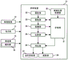
Fig. 13 is a diagram showing an example of a fracture detection device in embodiment 1. The control device 13 includes, for example, a storage unit 21, an extraction unit 22, an extraction unit 23, a detection unit 24, a car position detection unit 25, a determination unit 26, an operation control unit 27, and a notification unit 28. Fig. 13 shows an example in which the control device 13 has a function of detecting the presence of the broken portion 4c of the main rope 4. A dedicated device for detecting the fracture portion 4c may be provided in the elevator apparatus. Hereinafter, the function and operation of the fracture detection device will be described in detail with reference to fig. 14 to 28. Fig. 14 is a flowchart showing an example of the operation of the fracture detection apparatus according to embodiment 1.
The extraction unit 22 extracts a vibration component of a specific frequency band from the sensor signal (S101). In the example shown in the present embodiment, the weighing signal, the speed deviation signal, and the torque signal are used as the sensor signals. As another example, an acceleration signal from an accelerometer (not shown) provided in the car 1 may be used as the sensor signal. In the following, an example in which a torque signal is used as a sensor signal will be described in detail. In S101, the extraction unit 22 extracts a vibration component of a specific frequency band from the torque signal.
For example, when the breaking portion 4c shown in fig. 3 comes into contact with the release preventing member 19, an abnormal variation occurs in the torque signal from the hoisting machine 11. The abnormal fluctuation has a vibration component of a natural frequency band corresponding to the length of the breaking portion 4c and the moving speed of the main rope 4. When the length of the breaking portion 4c is d m and the moving speed of the main rope 4 is v m/s, the frequency f Hz of the abnormal vibration can be expressed by the following equation.
[ formula 1]
f=v/d…(1)
Fig. 15 is a diagram for explaining an example of the function of the 1 st extraction unit. In the example shown in the present embodiment, the 1 st extraction unit is the extraction unit 22. The extraction unit 22 includes, for example, a band-pass filter 32. For the sake of simplicity of description, in the drawings and the like, the band pass filter is also expressed as BPF. The torque signal from the hoisting machine 11 is input to the band-pass filter 32. The band-pass filter 32 extracts a vibration component of a specific frequency band including the frequency f from the input torque signal. The length d of the breaking portion 4c is set in advance. For example, as the length d, the length of the loosened strand when the strand is loosened by an amount of 0.5 pitch to several pitches is set. The moving speed v is determined according to the moving speed of the car 1. For example, the moving speed v of the main rope 4 may be calculated from the rated speed of the car 1.
As shown in fig. 15, the extraction unit 22 may further include an amplifier 33. The amplifier 33 for example squares the signal u. The extracting unit 22 may obtain the signal u output from the amplifier 332The square root of (a). The absolute value of the signal u may be obtained by the extracting unit 22 so that the sign of the signal is positive. In the following description, the signal output from the extracting unit 22 is expressed as an output signal Y. When the extraction unit 22 includes the band pass filter 32, the signal output from the extraction unit 22 is also expressed as the output signal Y of the band pass filter 32.
Fig. 15 shows an example in which the extraction unit 22 includes a band-pass filter 32 to filter an input torque signal. The extraction unit 22 may include a nonlinear filter to extract a vibration component of a specific frequency band. The adaptive filter algorithm may be applied to the extraction unit 22 to extract the vibration component of a specific frequency band.
The extraction unit 23 extracts a determination signal from the vibration component extracted by the extraction unit 22 (S102). The determination signal is a signal necessary for determining that sudden fluctuation has occurred in the sensor signal. The extraction unit 23 attenuates the trend component among the vibration components extracted by the extraction unit 22, thereby obtaining a determination signal from the vibration components extracted by the extraction unit 22. The trend component is a component of a tendency of long-term change in vibration during travel of the car 1 of approximately 1000 times in recent years, for example. The trend component includes, for example, a steady vibration component and a gradual vibration component.
Fig. 16 to 18 are diagrams showing changes in the variation generated in the sensor signal. In fig. 16 to 18, the vertical axis shows values corresponding to the amplitude of the fluctuation generated in the sensor signal. The horizontal axis represents the number of starts of the elevator. The horizontal axis may also be the elapsed time from installation of the elevator. The horizontal axis may be the position P where the car 1 passes1The number of times.
Fig. 16 shows when the car 1 passes the position P1The value of the resulting output signal Y. At the time of the number of activation M1, the main rope 4 does not have the broken portion 4 c. Fig. 16 shows an example in which a broken portion 4c is generated in the main rope 4 when the number of starts is M2. As described above, breakThe crack 4c suddenly occurs due to breakage of the wire rod. Therefore, the sensor signal fluctuation due to the fracture portion 4c occurs suddenly. When the breakage portion 4c is generated in the main rope 4, the value of the output signal Y suddenly becomes larger than the value immediately before.
Fig. 19 is a diagram for explaining transition of fluctuation generated in the sensor signal. Fig. 19 shows a transition when the car 1 reciprocates twice between the lowermost layer and the position P after the main rope 4 has a broken portion 4 c. In the example shown in fig. 19, the car 1 is at time t1Time t2Time t5And time t6Passing through position P1. Fig. 19 (b) shows the torque of the hoisting machine 11. Fig. 19 (c) shows the value of the output signal Y. When the main rope 4 has a broken portion 4c, the car 1 passes through the position P every time it passes through the position P1At this time, the breaking portion 4c comes into contact with the escape preventer 19. Therefore, when the breakage 4c occurs in the main rope 4, the position P is set1The value of the output signal Y at (a) continues to show a larger value also afterwards.
Figure 17 shows when the car 1 passes the position P2The value of the resulting output signal Y. As described above, the amount of oil coated on the guide rail does not change abruptly. The oil coated on the rail is gradually reduced and eventually exhausted if not supplied. Therefore, the variation of the sensor signal due to the joint of the rail member 20 gradually increases with the passage of time as shown in fig. 17. Similarly to the variation of the sensor signal due to the joint of the rail member 20, the variation of the sensor signal due to the pulley abnormality gradually increases with the passage of time as shown in fig. 17.
Fig. 17 shows an example of the output signal Y having a gradually increasing vibration component. The increasing vibration component is a vibration component that gradually grows with time in the vibration components extracted by the extraction unit 22. For example, the increasing vibration component is the following vibration component: the hoisting machine torque signal fluctuates at a rate of about 1[ N/m ] in response to the fluctuation of the sensor signal after the oil is supplied to the rail when the car 1 passes through the joint of the rail member 20 1000 times. The extraction unit 23 attenuates the vibration component as shown in fig. 17.
Fig. 18 shows the value of the output signal Y obtained when the car 1 passes a certain position. As shown in fig. 18, the variation in the sensor signal due to friction always shows the same value. Fig. 18 shows an example of the output signal Y having a stable vibration component. The stable vibration component is a vibration component that is generated stably, such as a DC component, among the vibration components extracted by the extraction unit 22. The steady vibration component may also contain a vibration component that fluctuates more slowly than the increasing vibration component. For example, a vibration component that requires 1000 or more activation times (passing through the joint) to fluctuate the hoisting machine torque signal by 1[ N/m ] may be included in the stable vibration component. The extraction unit 23 attenuates the vibration component as shown in fig. 18.
Fig. 20 is a three-dimensional graph showing changes in fluctuations occurring in the sensor signal. Fig. 20 corresponds to a diagram in which the signals shown in fig. 16 and the signals shown in fig. 17 are combined and displayed.
Fig. 21 is a diagram for explaining an example of the function of the 2 nd extraction unit. In the example shown in the present embodiment, the 2 nd extraction unit is the extraction unit 23. The extraction unit 23 includes, for example, a low-pass filter 34 and a subtractor 35. For the sake of simplicity of description, the low-pass filter is also expressed as an LPF in the drawings and the like. The output signal Y of the band-pass filter 32 is input to the low-pass filter 34. The subtractor 35 is input with the output signal Y of the band-pass filter 32 and the output signal Z of the low-pass filter 34. The subtractor 35 outputs a difference signal Y-Z between the output signal Y of the band-pass filter 32 and the output signal Z of the low-pass filter 34 as a determination signal. The output signal Y-Z of the subtractor 35 is input to the detection section 24.
Fig. 22 is a diagram for explaining an example of mounting the 1 st extraction unit and the 2 nd extraction unit. Fig. 22 (a) shows the torque of the hoisting machine 11. The torque signal shown in fig. 22 (a) is input to the band-pass filter 32. FIG. 22 (b) shows an output signal u of the amplifier 332. Output signal u of amplifier 332Is a continuous signal. The extracting unit 22 extracts the continuous output signal u2And (4) discretizing. In the example shown in fig. 22, the extraction unit 22 outputs the discretized signal as the output signal Y of the band-pass filter 32.
For example, the section in which the car 1 moves is virtually divided into a plurality of unit sections that are continuous in the vertical direction, and fig. 22 shows an example in which the unit sections are set for each predetermined height. For example, a zone of 0m to 0.3m in the car position is set as the 1 st unit zone. The zone of 0.3m to 0.6m of the car position is set as the 2 nd unit zone. The 2 nd unit section is a section immediately above the 1 st unit section. The zone of 0.6m to 0.9m of the car position is set as the 3 rd unit zone. The 3 rd unit section is a section immediately above the 2 nd unit section. The same applies to the section above the 3 rd unit section. For the sake of simplicity, in the drawings and the like, the nth unit section is also expressed as a section n.
The extracting unit 22 extracts one signal per unit section to extract a continuous output signal u2And (4) discretizing. For example, the extracting unit 22 extracts the signal u having the maximum value in one unit section2Extracted as the output signal Y of the unit interval.
The extraction unit 23 includes a low-pass filter 34 corresponding to each unit section. For example, the low-pass filter 34 corresponding to the 1 st unit section is expressed as a filter 34-1. The low-pass filter 34 corresponding to the 2 nd unit section is expressed as a filter 34-2. The low-pass filter 34 corresponding to the 3 rd unit section is expressed as a filter 34-3. Similarly, the low-pass filter 34 corresponding to the nth unit section is expressed as a filter 34-n.
The output signal Y of the band-pass filter 32 when the car 1 moves in the 1 st unit section is input to the filter 34-1. The output signal Z from the filter 34-1 corresponds to the trend component in the 1 st unit interval. The output signal Z from the filter 34-1 is input to the subtractor 35. The filter 34-2 is inputted with the output signal Y of the band pass filter 32 when the car 1 moves in the 2 nd unit section. The output signal Z from the filter 34-2 corresponds to the trend component in the 2 nd unit interval. The output signal Z from the filter 34-2 is input to the subtractor 35.
The filter 34-3 is inputted with the output signal Y of the band pass filter 32 when the car 1 moves in the 3 rd unit section. The output signal Z from the filter 34-3 corresponds to the trend component in the 3 rd unit interval. The output signal Z from the filter 34-3 is input to the subtractor 35. Similarly, the filter 34-n is inputted with the output signal Y of the band-pass filter 32 when the car 1 moves in the nth unit section. The output signal Z from the filter 34-n corresponds to the trend component in the nth unit interval. The output signal Z from the filter 34-n is input to a subtractor 35.
The subtractor 35 outputs a difference signal between the output signal Y of the band-pass filter 32 and the output signal Z from the filter 34-1 when the car 1 moves in the 1 st unit section as a determination signal in the 1 st unit section. The subtractor 35 outputs a difference signal between the output signal Y of the band-pass filter 32 and the output signal Z from the filter 34-2 when the car 1 moves in the 2 nd unit section as a determination signal in the 2 nd unit section. The subtractor 35 outputs a difference signal between the output signal Y of the band-pass filter 32 and the output signal Z from the filter 34-3 when the car 1 moves in the 3 rd unit section as a determination signal in the 3 rd unit section. Similarly, the subtractor 35 outputs a difference signal between the output signal Y of the band-pass filter 32 and the output signal Z from the filter 34-n when the car 1 moves in the nth unit section as the determination signal in the nth unit section.
Fig. 21 and 22 show an example in which the trend component of the output signal Y is obtained by performing low-pass filtering processing on the output signal Y of the band-pass filter 32. In order to realize such a function, it is necessary to set the time constant of the low-pass filter 34 to a value large to some extent.
For example, if oil is not supplied to the guide rail, TF is the number of times the car 1 travels until the value of the fluctuation of the sensor signal due to the joint of the rail member 20 reaches an abnormal value from a normal value1. The normal value is, for example, a value of fluctuation of a sensor signal obtained by moving the car 1 in a state where oil is sufficiently applied to the guide rails immediately after the elevator is installed. The abnormal value is a value of fluctuation of the sensor signal set in advance as an abnormal value. Further, TF is set as the number of times the car 1 travels, which is required to return the value of the variation in the sensor signal from the abnormal value to the normal value by supplying oil to the guide rail2。
Number of times of travel TF2Specific number of times of travel TF1Less. The time constant of the low-pass filter 34 is preferably dependent on the number of travels TF2To set it. As an example, the time constant is set such that the output of the low-pass filter 34 follows a fixed input value by passing the car 1 through a certain joint of the track member 20 1000 ± 200 times.
As another example, the time constant of the low-pass filter 34 may be switched according to the number of times the car 1 travels. For example, the time constant of the low-pass filter 34 is set based on the number of times of travel TF from the time when oil is supplied to the guide rail until the number of times of travel of the car 1 reaches the reference number of times 21, is set. When the number of times of travel of the car 1 after the refueling reaches the reference number of times, the time constant of the low-pass filter 34 is switched from the 1 st set value to the 2 nd set value. The 2 nd set point is a value larger than the 1 st set point. The 2 nd setting value is based on, for example, the number of times of travel TF1To set it. This makes it possible to obtain a trend component corresponding to the state of the oil.
Fig. 23 to 25 are diagrams showing examples of signals input to the subtractor 35. In fig. 23 to 25, the black dots indicate the output signal Y of the band-pass filter 32. The white squares represent the output signal Z of the low-pass filter 34. Fig. 23 shows an example in which the output signal Y shown in fig. 16 is input to the subtractor 35. As described above, when the breakage portion 4c is generated in the main rope 4, the output signal Y sharply increases. On the other hand, the output signal Z of the low-pass filter 34 does not follow a sharp change in the output signal Y. Therefore, the difference between the output signal Y and the output signal Z is suddenly increased by the occurrence of the broken portion 4c in the main rope 4. After the occurrence of the fracture 4c, the difference between the output signal Y and the output signal Z gradually decreases.
Fig. 24 shows an example in which the output signal Y shown in fig. 17 is input to the subtractor 35. As described above, when the oil of the rail surface decreases, the value of the output signal Y gradually becomes larger. In the case where a slow change occurs in the output signal Y as shown in fig. 17, the output signal Z follows the change in the output signal Y. Therefore, in the example shown in fig. 24, the output signal Y and the output signal Z have the same value.
Fig. 25 shows an example in which the output signal Y shown in fig. 18 is input to the subtractor 35. In the case where a slow change occurs in the output signal Y as shown in fig. 18, the output signal Z follows the change in the output signal Y. Therefore, in the example shown in fig. 25, the output signal Y and the output signal Z also have the same value.
In order to prevent false detection, a value other than 0 is preferably set as the initial value of the low-pass filter 34. When 0 is output as the initial value of the output signal Z of the low-pass filter 34, for example, when the car 1 passes through the joint of the track member 20 and a large value is output as the initial value of the output signal Y, the value of the determination signal Y-Z suddenly increases and false detection occurs. The determination signal Y-Z at this time is the difference between the initial value of the output signal Y and the initial value of the output signal Z. If a value other than 0 is set as the initial value of the output signal Z, the value of the determination signal Y-Z does not suddenly become large even if a large value is output as the initial value of the output signal Y. Therefore, false detection can be prevented. For example, it is preferable that a value obtained by multiplying a 1 st threshold value, which will be described later, by a coefficient of 1 or more be set as an initial value of the low-pass filter 34.
Fig. 21 and 22 show an example in which the extraction unit 23 includes the low-pass filter 34. The extraction unit 23 may extract the determination signal without the low-pass filter 34. For example, the extraction unit 23 may calculate the tendency component of the vibration from the moving average value of the output signal Y of the band pass filter 32. The extraction unit 23 calculates a moving average value from the output signal Y of the latest 20 times, for example. As another example, the extracting unit 23 may calculate the trend component of the vibration using a machine learning algorithm such as a neural network. That is, the extraction unit 23 may have a learning function. The above is just an example. The extraction unit 23 may calculate a moving average value from the output signal Y of any number of times in the past, for example. The arbitrary number of times is, for example, a number included in 10 to 100 times.
Fig. 26 is a diagram showing another example of the function of the 2 nd extraction unit. The extraction unit 23 includes, for example, a high-pass filter 36. For simplicity of description, the high pass filter is also expressed as an HPF in the drawings and the like. In the case where the low-pass filter 34 shown in fig. 21 is designed using the transfer function of the first-order delay system, the output signal Y-Z of the subtractor 35 is represented by the following expression.
[ formula 2]

In equation 2, s is the laplacian operator. τ is the time constant. The transfer function in equation 2 is that of a first order high pass filter. That is, the extracting unit 23 can realize the same function as the example shown in fig. 21 also in the example shown in fig. 26. In the example shown in fig. 26, the output signal Y of the band-pass filter 32 is input to the high-pass filter 36. The high-pass filter 36 outputs a signal corresponding to the output signal Y-Z of the subtractor 35 as a determination signal.
Fig. 27 is a view for explaining another example of mounting the 1 st extraction unit and the 2 nd extraction unit. Fig. 27 shows an example in which the extracting unit 23 includes the high-pass filter 36. Fig. 27 (a) shows the torque of the hoisting machine 11. The torque signal shown in fig. 27 (a) is input to the band-pass filter 32. FIG. 27 (b) shows an output signal u of the amplifier 332. The extracting unit 22 extracts the continuous output signal u2And (4) discretizing. Similarly to the example shown in fig. 22, the extraction unit 22 outputs the discretized signal as the output signal Y of the band-pass filter 32.
In the example shown in fig. 27, the zone in which the car 1 moves is also virtually divided into a plurality of unit zones that are continuous in the vertical direction. The extracting unit 22 extracts, for example, a signal u having a maximum value in one unit section2And extracted as the output signal Y of the unit section.
The extraction unit 23 includes a high-pass filter 36 corresponding to each unit section. For example, the high-pass filter 36 corresponding to the 1 st unit section is expressed as a filter 36-1. The high-pass filter 36 corresponding to the 2 nd unit interval is expressed as a filter 36-2. The high-pass filter 36 corresponding to the 3 rd unit section is expressed as a filter 36-3. Similarly, the high-pass filter 36 corresponding to the nth unit interval is expressed as a filter 36-n.
The filter 36-1 is inputted with the output signal Y of the band pass filter 32 when the car 1 moves in the 1 st unit section. The filter 36-1 outputs a signal in which the trend component is attenuated from the output signal Y. The output signal Y-Z from the filter 36-1 is the determination signal in the 1 st unit section. The filter 36-2 is inputted with the output signal Y of the band pass filter 32 when the car 1 moves in the 2 nd unit section. The filter 36-2 outputs a signal in which the trend component is attenuated from the output signal Y. The output signal Y-Z from the filter 36-2 is the determination signal in the 2 nd unit section.
The filter 36-3 is inputted with the output signal Y of the band pass filter 32 when the car 1 moves in the 3 rd unit section. The filter 36-3 outputs a signal in which the trend component is attenuated from the output signal Y. The output signal Y-Z from the filter 36-3 is a determination signal in the 3 rd unit section. Similarly, the filter 36-n is input to the output signal Y of the band-pass filter 32 when the car 1 moves in the nth unit section. The filter 36-n outputs a signal in which the trend component is attenuated from the output signal Y. The output signal Y-Z from the filter 36-n is a determination signal in the nth unit interval.
The detection unit 24 detects that abnormal fluctuation has occurred in the sensor signal based on the determination signal extracted by the extraction unit 23 (S103). The detection unit 24 detects sudden fluctuations occurring in the sensor signal as abnormal fluctuations. For example, the detection unit 24 determines whether or not the value of the determination signal extracted by the extraction unit 23 exceeds the 1 st threshold. The detection unit 24 detects that an abnormal variation has occurred in the sensor signal when the value of the determination signal extracted by the extraction unit 23 exceeds the 1 st threshold value. The 1 st threshold is stored in the storage unit 21 in advance.
The control device 13 may set the 1 st threshold value by performing a specific operation for actually moving the car 1. For example, when the installation of the elevator is completed, the setting operation for setting the 1 st threshold value is performed. In the setting operation, the car 1 moves from the lowermost floor to the uppermost floor. The car 1 can also be moved from the uppermost floor to the lowermost floor. The signal Y output from the extracting unit 22 when the car 1 moves between the lowermost floor and the uppermost floor is stored in the storage unit 21. Then, a value obtained by multiplying the maximum value of the output signal Y stored in the storage unit 21 by a coefficient is set as the 1 st threshold. The coefficient is a value of 1 or more. The coefficient may also be 2. The coefficient may be adjusted according to the magnitude of the vibration of the car 1 generated during normal operation.
The controller 13 may update the 1 st threshold value that is temporarily set by performing a specific operation to actually move the car 1. For example, at night when the elevator is frequently used, an update operation for updating the 1 st threshold value is performed. The contents of the update operation may be the same as those of the setting operation. The controller 13 periodically performs, for example, an update operation to update the 1 st threshold value. For example, every month, the refresh operation is performed. This enables the 1 st threshold to be reset appropriately according to the state of the elevator.
The control device 13 may perform the setting operation a plurality of times by changing the speed of the car 1. For example, the control device 13 moves the car 1 at the 1 st speed to perform the 1 st setting operation. The control device 13 sets the 1 st threshold for low speed by performing the 1 st setting operation. The control device 13 moves the car 1 at the 2 nd speed to perform the 2 nd setting operation. The 2 nd speed is a speed faster than the 1 st speed. The control device 13 sets the 1 st threshold for high speed by performing the 2 nd setting operation. In an elevator apparatus in which the maximum speed of the car 1 can be changed, the detection unit 24 selects an appropriate 1 st threshold value corresponding to the maximum speed of the car 1. For example, when the high-speed mode operation is performed, the detection unit 24 compares the value of the determination signal with the 1 st threshold for high speed. When the low-speed mode operation is performed, the detection unit 24 compares the value of the determination signal with the 1 st threshold value for low speed. Similarly, the control device 13 may perform the refresh operation a plurality of times by changing the speed of the car 1.
The lower limit value of the 1 st threshold may be stored in the storage unit 21 in advance. For example, when the 1 st threshold calculated by performing the setting operation does not reach the lower limit value, the lower limit value is set as the 1 st threshold. When the 1 st threshold calculated by performing the update operation does not reach the lower limit value, the lower limit value is set as the 1 st threshold. This can prevent the extremely small value from being set as the 1 st threshold value.
The car position detecting unit 25 detects the position of the car 1. The car position detecting unit 25 detects the car position based on, for example, the rotation signal output from the encoder 18. The car position detecting unit 25 may detect the car position by another method. For example, the hoisting machine 11 is provided with an encoder. An encoder provided in the hoisting machine 11 is also an example of a sensor that outputs a signal corresponding to the position of the car 1. The car position detecting unit 25 may detect the car position based on an encoder signal from the hoisting machine 11. The governor 15 may have a function of detecting the position of the car 1. The hoisting machine 11 may be provided with a function of detecting the car position. In the above case, a signal indicating the position of the car 1 is input to the control device 13.
When the detection unit 24 detects that an abnormal variation has occurred in the sensor signal, the position of the car at the time of the occurrence of the variation is stored in the storage unit 21. For example, when the section in which the car 1 moves is divided into a plurality of unit sections, and the detection unit 24 detects an abnormal change, information for specifying the unit section in which the change has occurred is stored in the storage unit 21.
When the detection unit 24 detects that an abnormal change has occurred in the sensor signal, the determination unit 26 determines whether or not the main rope 4 has the broken portion 4c (S104). When the detection unit 24 detects the occurrence of the abnormal fluctuation, the determination unit 26 performs the above determination based on the car position at the time of the occurrence of the fluctuation. The judgment unit 26 includes, for example, a reproducibility judgment function 26-1 and a fracture judgment function 26-2. The reproducibility judgment function 26-1 judges whether or not there is reproducibility of the car position in which the abnormal fluctuation has occurred (S104-1). The breakage determination function 26-2 determines whether or not the main rope 4 has the breakage portion 4c based on the determination result of the reproducibility determination function 26-1 (S104-2).
Fig. 28 is a diagram for explaining an example of the reproducibility judgment function 26-1. Fig. 28 (a) shows the latest determination signal obtained when the car 1 has moved in the section from the position 0 to the position P. In the example shown in fig. 28 (a), the position P is set1And position P3At this point, the value of the determination signal exceeds the 1 st threshold TH 1. Fig. 28 (b) shows a determination signal obtained when the car 1 has moved in the same section last time. That is, the determination signal shown in fig. 28 (a) is obtained immediately after the acquisitionThe signal obtained when the car 1 moves again in the same section after the determination signal shown in fig. 28 (b). In the example shown in fig. 28 (b), the position P is1Position P3And position P4At this point, the value of the determination signal exceeds the 1 st threshold TH 1.
The reproducibility judgment function 26-1 judges that there is reproducibility when the value of the judgment signal exceeds the 1 st threshold value two consecutive times when the car 1 passes the same position a plurality of times, for example. For example, at position P1And position P3Here, the value of the determination signal exceeds the threshold TH1 twice in succession. Therefore, the reproducibility determination unit 26-1 determines that the position is P1And position P3There is reproducibility. On the other hand, at position P4Here, the latest value of the determination signal does not exceed the 1 st threshold TH 1. In the above case, the reproducibility determination unit 26-1 does not determine that the position is P4There is reproducibility. Position P shown in FIG. 28 (b)4The value of (b) is determined to have occurred due to a situation of no reproducibility. For example, the position P shown in (b) of FIG. 284The value of (b) is determined to have occurred due to the passenger jumping inside the car 1.
When the section in which the car 1 moves is divided into a plurality of unit sections, the following determination is performed, for example. The reproducibility judgment function 26-1 judges that there is reproducibility if the value of the judgment signal exceeds the 1 st threshold value two consecutive times when the car 1 passes the same unit section a plurality of times. For example, when the value of the determination signal obtained when the car 1 passes through the 5 TH unit section exceeds the 1 st threshold TH1 twice in succession, the reproducibility judgment function 26-1 judges that there is reproducibility in the 5 TH unit section.
The reproducibility judgment function 26-1 may judge that there is reproducibility when the value of the judgment signal exceeds the 1 st threshold value three or more times in succession. The number of times for determining the presence of reproducibility is set arbitrarily.
When the reproducibility judgment function 26-1 judges that there is reproducibility in the car position in which the abnormal fluctuation has occurred, the breakage judgment function 26-2 judges that the main rope 4 has a broken portion 4 c. When the fracture determination function 26-2 determines that the fracture 4c has occurred, the operation control unit 27 stops the car 1 at the nearest floor (S105). The notification unit 28 also notifies the management company of the elevator (S106).
In the breakage detection device shown in the present embodiment, the presence of the breakage portion 4c is detected by a sensor that changes an output signal when the main rope 4 vibrates. As the sensor signal, for example, a weighing signal, a speed deviation signal, and a torque signal can be used. Therefore, it is not necessary to provide a dedicated sensor for determining the presence or absence of the fracture portion 4 c. Further, the presence of the breaking portion 4c can be detected by the presence of at least one sensor. It is not necessary to provide a plurality of sensors for determining the presence or absence of the fracture portion 4 c. Therefore, the structure of the fracture detection device can be simplified.
In the fracture detection device shown in the present embodiment, the trend component in the vibration component extracted by the extraction unit 22 is attenuated, and thereby the determination signal is extracted from the vibration component extracted by the extraction unit 22. Therefore, even if the sensor signal includes a variation due to the joint of the rail member 20, the detection accuracy is not deteriorated. Even if the sensor signal includes a variation due to a sheave abnormality, the detection accuracy is not deteriorated. The fracture detection device according to the present embodiment can detect the presence of the fracture part 4c with high accuracy.
In the present embodiment, an example in which the fracture detection device always performs the same operation during the period from the start of movement of the car 1 to the stop thereof is described. This is just an example. For example, in an elevator apparatus, when the car 1 starts moving, a transient response of speed control occurs due to a difference between the mass of the car 1 and the mass of the counterweight 3. Therefore, immediately after the car 1 starts moving, the torque signal from the hoisting machine 11 and the like are likely to fluctuate. In order to prevent the detection accuracy from being deteriorated due to such a variation, the function of the extraction portion 22 may be stopped immediately after the car 1 starts moving. Alternatively, immediately after the car 1 starts moving, the output signal Y of the band-pass filter 32 may be forcibly set to 0.
As another example of preventing the deterioration of the detection accuracy, the detection unit 24 may determine the signal immediately after the car 1 starts movingWhen the value of the number exceeds the 2 nd threshold value, it is detected that the sensor signal has abnormally changed. The 2 nd threshold is a value larger than the 1 st threshold. Immediately after the car 1 starts moving, for example, the speed from the start of the car 1 to the time when the car 1 moves to the speed V1The period of time (c). Velocity V1Is stored in the storage unit 21 in advance. Immediately after the car 1 starts moving, the time period from when the car 1 starts moving to when the acceleration of the car 1 becomes constant may be referred to.
In the elevator apparatus, a ripple is generated in the torque of the hoisting machine 11. In order to prevent the detection accuracy from being deteriorated due to the torque ripple, the function of the extraction portion 22 may be stopped immediately after the car 1 starts moving and before the car 1 stops. Alternatively, the output signal Y of the band-pass filter 32 may be forcibly set to 0 immediately after the car 1 starts moving and before the car 1 comes to a stop.
As another example of preventing the detection accuracy from being deteriorated, the detection unit 24 may detect that an abnormal variation has occurred in the sensor signal when the value of the determination signal exceeds the 3 rd threshold value immediately after the car 1 starts moving and immediately before the car 1 stops. The 3 rd threshold is a value larger than the 1 st threshold. The term "immediately after the car 1 starts moving" and "immediately before the car 1 stops" means, for example, a speed-specific speed V of the car 12A slow period. Velocity V2Is stored in the storage unit 21 in advance. Velocity V2For example, the speed is set to a speed at which the frequency band of the torque ripple of the hoisting machine 11 is deviated from the natural frequency band due to the contact of the breaking portion 4c with the stopper.
In the present embodiment, an example is shown in which the zone in which the car 1 moves is divided into a plurality of unit zones. Hereinafter, a preferred example of division will be described.
In the example shown in fig. 22, when the detection unit 24 detects that an abnormal variation has occurred in the sensor signal, the number of the unit section in which the variation has occurred is stored in the storage unit 21, for example. When the moving section of the car 1 is divided into n unit sections, n storage areas for storing the abnormal variation are necessary in the storage unit 21. Therefore, when the number of divided unit sections increases, the generation position of the fracture portion 4c can be accurately determined, but the capacity of the storage unit 21 needs to be increased. On the other hand, if the number of divided unit sections is small, the generation position of the fracture portion 4c cannot be accurately specified although the capacity of the storage portion 21 does not need to be increased.
Fig. 29 is a cross-sectional view of the diverting pulley 7. In the example shown in fig. 29, the breaking portion 4c of the main rope 4 contacts the opposing portion 19b of the stopper 19 and then contacts the opposing portion 19 a. It is not possible to detect the variation in the sensor signal when the breaking portion 4c contacts the opposing portion 19b and the variation in the sensor signal when the breaking portion 4c contacts the opposing portion 19a as different abnormal variations. When the length from the portion of the main rope 4 facing the facing portion 19b to the portion facing the facing portion 19a is L1, there is no problem even if the height of the unit section is greater than the rope length L1. The rope length L1 is determined based on, for example, the smallest sheave among the sheaves around which the main rope 4 is wound. The rope length L1 may be determined based on a pulley of the most common size among the pulleys around which the main rope 4 is wound.
Fig. 30 is a view showing the car 1 guided by the guide rails. As described above, the guide rail includes the plurality of rail members 20. Preferably, a variation in the sensor signal when the car 1 passes through a certain joint of the rail member 20 and a variation in the sensor signal when the car passes through the previous joint of the joint are detected as different abnormal variations. Preferably, when the length of the rail member 20 is L2, the height of the unit section is smaller than the length L2 of the rail member 20. The length L2 is determined based on the shortest rail member 20 among the rail members 20, for example. The length L2 may be determined based on the rail member 20 having the most common length among the rail members 20.
Preferably, the height H of each unit section satisfies the following condition, where H is the height of the unit section.
[ Length L1] ≦ height H ≦ Length L2 of Rail Member 20 ]
In the present embodiment, an example of detecting the presence of the fracture portion 4c without considering the moving direction of the car 1 is described. This is just an example. The presence of the broken portion 4c may be detected in a case where the car 1 moves upward and a case where the car 1 moves downward.
In the above case, when the detection unit 24 detects that an abnormal variation has occurred in the sensor signal, the car position and the moving direction of the car 1 at the time of the occurrence of the variation are stored in the storage unit 21. The reproducibility judgment function 26-1 also judges whether or not there is reproducibility of the car position where the abnormal fluctuation has occurred, in consideration of the moving direction of the car 1.
In consideration of the moving direction of the car 1, for example, an upward traveling setting operation for moving the car 1 from the lowermost floor to the uppermost floor is performed, and the upward traveling 1 st threshold value is set. A descending setting operation for moving the car 1 from the uppermost floor to the lowermost floor is performed, and a 1 st threshold value for descending is set. Further, an upward traveling update operation for moving the car 1 from the lowermost floor to the uppermost floor is performed, and the upward traveling 1 st threshold is updated. The setting operation for descending is performed to move the car 1 from the uppermost floor to the lowermost floor, and the 1 st threshold for descending is updated. For example, when the value of the determination signal exceeds the 1 st threshold value twice consecutively when the car 1 passes through the same position in the same direction, the reproducibility judgment function 26-1 judges that there is reproducibility.
In the present embodiment, an example of determining that there is reproducibility when the value of the determination signal exceeds the 1 st threshold value a plurality of times in succession when the car 1 passes through the same position is described. This is just an example. The determination unit 26 may determine whether or not the broken portion 4c exists in the main rope 4 based on the frequency of occurrence of abnormal variation detected by the detection unit 24 when the car 1 passes through the same position.
For example, when the detection unit 24 detects that an abnormal variation has occurred in the sensor signal, the car position at the time of the occurrence of the variation is stored in the storage unit 21. When the section in which the car 1 moves is divided into a plurality of unit sections, the number of the unit section in which the fluctuation occurs is stored in the storage unit 21. For example, a storage area corresponding to each unit section is formed in the storage unit 21. When the detection unit 24 detects that an abnormal change has occurred when the car 1 has moved in a certain unit section, "1" is stored in the storage area corresponding to the unit section. If the detection unit 24 does not detect that an abnormal change has occurred when the car 1 has moved in a certain unit section, "0" is stored in the storage area corresponding to the unit section.
The reproducibility judgment function 26-1 calculates, for example, a moving average of the values stored in the storage area as the frequency. For example, the reproducibility judgment function 26-1 calculates a moving average value when the car 1 passes the same position four times. The breakage determination function 26-2 determines whether or not the main rope 4 has the breakage portion 4c based on the frequency calculated by the reproducibility determination function 26-1. For example, the breakage determination function 26-2 determines that the main rope 4 has the broken portion 4c when the moving average calculated by the reproducibility determination function 26-1 exceeds the 1 st determination threshold. The 1 st determination threshold is stored in the storage unit 21 in advance.
Fig. 31 is a diagram showing another example of the fracture detection device in embodiment 1. The example shown in fig. 31 is different from the example shown in fig. 13 in that the control device 13 further includes an arithmetic unit 29.
In the example shown in fig. 31, a determination score for determining whether or not the fracture portion 4c is present is stored. The calculation unit 29 calculates a determination score based on the result detected by the detection unit 24. For example, when the detection unit 24 detects that an abnormal change has occurred in the sensor signal, the car position at the time of the change is stored in the storage unit 21 in association with the determination score. The determination unit 26 determines whether or not the main rope 4 has the broken portion 4c based on the determination score stored in the storage unit 21. When the section in which the car 1 moves is divided into a plurality of unit sections, the determination scores corresponding to the respective unit sections are stored in the storage unit 21.
Fig. 32 and 33 are diagrams illustrating examples of the breaking portion 4 c. Fig. 32 shows an example in which the broken portion 4c moves away from the diverting pulley 7 as it approaches the end. As shown in fig. 32, when the broken portion 4c protrudes from the surface of the main rope 4, the broken portion 4c comes into contact with the slipping-off preventive piece 19 when passing through the diverting pulley 7. Fig. 33 shows an example in which the breaking portion 4c is arranged along the surface of the diverting pulley 7. As shown in fig. 33, when the broken portion 4c protrudes from the surface of the main rope 4, the broken portion 4c does not contact the stopper 19 when passing through the diverting pulley 7. Therefore, even if the breaking portion 4c passes through the diverting sheave 7, the main rope 4 does not vibrate.
The breaking portion 4c may change its direction by coming into contact with the escape preventer 19. When the direction of the breaking portion 4c is changed from the direction shown in fig. 32 to the direction shown in fig. 33, the main ropes 4 do not vibrate any more even if the breaking portion 4c passes through the diverting sheave 7. On the other hand, the broken portion 4c may be pushed by the surface of the groove and change its direction when passing through the diverting pulley 7. The direction of the fracture 4c may change due to further loosening of the wire or strand. When the direction of the breaking portion 4c is changed from the direction shown in fig. 33 to the direction shown in fig. 32, the main ropes 4 vibrate when the breaking portion 4c passes through the diverting sheave 7.
Fig. 34 is a diagram for explaining an example of the functions of the arithmetic unit 29 and the determination unit 26. Fig. 34 (a) shows the position of the car 1. Fig. 34 (b) shows the torque of the hoisting machine 11. Fig. 34 (c) shows a determination signal. Fig. 34 (d) shows an example of transition of the determination score.
In the example shown in fig. 34, the car 1 reciprocates twice between the lowermost floor and the position P. Car 1 at time t1Time t2Time t5And time t6Passing through position P1. Fig. 34 shows an example in which the main rope 4 has a breaking portion 4 c. The breaking portion 4c at time t1Time t2Time t5And time t6Passing over the diverting pulley 7. As described above, even if the main rope 4 has the breaking portion 4c, the breaking portion 4c does not always contact the escape preventer 19. In the example shown in fig. 34, at time t1Time t5And time t6The breaking portion 4c contacts the escape preventer 19. The breaking portion 4c at time t2Without coming into contact with the release preventing member 19.
For example, when at time t1When the breaking portion 4c contacts the escape preventer 19, the value of the determination signal exceeds the 1 st threshold value. Thus, the detection unit 24 detects that an abnormal variation has occurred in the sensor signal. For example, consider position P1Including the case in the 8 th unit section. At time t1The determination score of the 8 th unit section is set as an initial value. The initial value is, for example, 0. When the detecting unit 24 detects that the abnormal variation occurs when the car 1 passes through the 8 th unit section, the computing unit 29 adds a fixed value to the determination score of the 8 th unit section. Fig. 34 (d) shows an example in which the fixed value for adding is 5.
The determination unit 26 determines whether or not the determination score stored in the storage unit 21 exceeds a 2 nd determination threshold. The 2 nd determination threshold is stored in the storage unit 21 in advance. Fig. 34 (d) shows an example in which the 2 nd determination threshold is 10. At time t1The determination score of the 8 th unit section does not exceed the 2 nd determination threshold value. The determination unit 26 determines that the main rope 4 does not have the broken portion 4c if the determination score does not exceed the 2 nd determination threshold.
Then, the car 1 is at time t6Passes the position P again1. The detection unit 24 detects that the time t is reached6An abnormal variation occurs in the sensor signal. Therefore, the arithmetic unit 29 adds 5 to the determination score of the 8 th unit segment stored in the storage unit 21. The 8 th unit section determination score stored in the storage unit 21 at time t6Becomes 14. At time t6The determination score of the 8 th unit section exceeds the 2 nd determination threshold value. Thus, the determination unit 26 determines at time t6The main rope 4 is judged to have a broken portion 4 c.
In the example shown in fig. 34, even if a time period in which the breaking portion 4c does not contact the escape preventer 19 occurs, the presence of the breaking portion 4c can be detected.
When the abnormal change is detected by the detection unit 24 when the car 1 passes the car position stored in the storage unit 21 again without dividing the section in which the car 1 moves into a plurality of unit sections, a fixed value is added to the determination score at that position. When the car 1 passes the position again, if the detection unit 24 does not detect the abnormal variation, a fixed value is subtracted from the determination score at the position. In the above case, the car position may be regarded as the same car position as long as the position is within the reference distance from the car position stored in the storage unit 21. The reference distance is set to, for example, a rope length L1.
The 2 nd determination threshold value is preferably a value 2 times or more the value added to the determination score. If the 2 nd determination threshold is a value that is 2 times or more the value added to the determination score, erroneous detection due to a situation with no reproducibility can be suppressed. In consideration of the possibility that the fracture portion 4c does not continuously contact the stopper 19, the value subtracted from the determination score is preferably a value equal to or less than one-half of the added value.
The 2 nd determination threshold may be variable according to the magnitude of the determination signal. For example, the 1 st and 2 nd values are set in advance as the 2 nd determination threshold values. The 2 nd value is a value greater than the 1 st value. When the magnitude of the determination signal is equal to or less than the reference value, the 2 nd value is used as the 2 nd determination threshold value. That is, when a variation occurs in the sensor signal such that the magnitude of the determination signal exceeds the reference value, the presence of the fracture section 4c can be detected as soon as possible. For example, when the following condition 1 is satisfied, the 2 nd determination threshold is set to 15. When the following condition 2 is satisfied, the 2 nd determination threshold is set to 10.
Condition 1: [ 1 st threshold ] ≦ [ decision signal ] ≦ 2 × [ 1 st threshold ]
Condition 2: 2 x [ 1 st threshold value ] < [ decision signal ]
Fig. 35 is a diagram showing an example of a signal input to the subtractor 35 of the 2 nd extraction unit. In fig. 35, a broken line indicates an output signal u of the amplifier 332. That is, the broken line indicates the output signal Y before discretization. In addition, white circles indicate the discretized output signal Y. The solid line represents the output signal Z of the low-pass filter 34. In fig. 35, the horizontal axis represents the car position. Fig. 35 shows signals obtained when the car 1 passes through the (n-1) th unit section, the (n) th unit section, and the (n +1) th unit section.
Fig. 35 (a) shows an example in which the output signal y (n) exceeding the 1 st threshold value exists in the nth unit interval. When the output signal y (n) is generated due to the joint of the rail member 20, the output signal z (n) of the nth unit section follows the output signal y (n). The value of the output signal z (n) becomes the same as the value of the output signal y (n). Therefore, the output signal y (n) -z (n) as the determination signal of the nth unit interval is a value smaller than the 1 st threshold value. In the example shown in fig. 35 (a), the detection unit 24 does not detect abnormal variation in the sensor signal in each of the (n-1) th unit segment, the (n) th unit segment, and the (n +1) th unit segment.
Fig. 35 (b) shows a signal when the car 1 passes through the (n-1) th unit zone, the (n) th unit zone, and the (n +1) th unit zone again immediately after the signal shown in fig. 35 (a) is acquired. In the example shown in fig. 35 (b), the output signal Y (n-1) exceeding the 1 st threshold value exists in the n-1 th unit section. The output signal Y (n-1) shown in fig. 35 (b) is an output signal in which the output signal Y (n) shown in fig. 35 (a) is shifted to the n-1 th unit interval. Such a situation occurs, for example, due to the main ropes 4 being elongated.
In the example shown in FIG. 35 (b), the output signal Z (n-1) in the (n-1) th unit section does not follow the rapid change of the output signal Y (n-1). Therefore, if the output signal Y (n-1) -Z (n-1) as the determination signal of the (n-1) th unit section is larger than the 1 st threshold value, the fracture determination function 26-2 may determine that the fracture section 4c is present. In the nth unit interval, the output signal y (n) rapidly decreases. The output signal z (n) does not follow the abrupt change of the output signal y (n). Therefore, the output signal y (n) -z (n) as the determination signal of the nth unit interval becomes a negative value.
In the present embodiment, a function for preventing such false detection will be described. The example of the fracture detection device of the present embodiment is the same as the example shown in fig. 13. As for functions not disclosed in this embodiment, any of the functions disclosed in embodiment 1 can be employed. For example, the control device 13 may further include a calculation unit 29.
Fig. 36 is a diagram for explaining an example of the function of the 2 nd extraction unit. Fig. 36 (a) is a view corresponding to fig. 35 (a). Fig. 36 (b) is a view corresponding to fig. 35 (b). In the example shown in the present embodiment, the extraction unit 23 outputs the signals Y to Z as determination signals, taking into account the values of the adjacent unit sections with respect to the output signal Z of the low-pass filter 34. For example, the extraction unit 23 outputs the determination signal as follows.
Unit interval n-1: y (n-1) -max (Z (n-2), Z (n-1), Z (n))
The nth unit interval: y (n) -max (Z (n-1), Z (n +1))
N +1 unit interval: y (n +1) -max (Z (n), Z (n +1), Z (n +2))
An example of calculating the determination signal of the nth unit section will be described below. The nth unit section is a section immediately below the (n +1) th unit section and immediately above the (n-1) th unit section. The extracting unit 23 determines a signal indicating the maximum value from the output signal Z (n) of the unit section, the output signal Z (n-1) of the next unit section, and the output signal Z (n +1) of the previous unit section. In the example shown in fig. 36 (a), the maximum value of the output signal z (n) among the 3 signals is shown. The extraction unit 23 outputs, as a determination signal, a difference signal between the output signal y (n) of the unit section and the output signal z (n) determined as a signal indicating the maximum value.
The extraction unit 23 similarly calculates the determination signal for the (n-1) th unit segment and the (n +1) th unit segment. In the example shown in fig. 36 (a), the determination signal is calculated as follows.
Unit interval n-1: y (n-1) -Z (n) < 0
The nth unit interval: y (n) -Z (n) about 0
N +1 unit interval: y (n +1) -Z (n) < 0
In the example shown in fig. 36 (a), the value of the output signal Z (n-2) is set to be smaller than the value of the output signal Z (n). The value of the output signal Z (n +2) is set smaller than the value of the output signal Z (n).
Fig. 36 (b) shows a signal when the car 1 passes through the (n-1) th unit zone, the (n) th unit zone, and the (n +1) th unit zone again immediately after the signal shown in fig. 36 (a) is acquired. The output signal Y (n-1) shown in fig. 36 (b) is an output signal in which the output signal Y (n) shown in fig. 36 (a) is shifted to the n-1 th unit interval.
In the example shown in fig. 36 (b), the determination signal is calculated as follows.
Unit interval n-1: y (n-1) -Z (n) about 0
The nth unit interval: y (n) -Z (n) < 0
N +1 unit interval: y (n +1) -Z (n) < 0
In the example shown in the present embodiment, it is possible to prevent the variation in the sensor signal due to the joint of the rail member 20 from being erroneously detected as the variation in the sensor signal due to the fracture portion 4 c.
Fig. 37 is a diagram showing an example of a fracture detection device in embodiment 3. The example shown in fig. 37 differs from the example shown in fig. 13 in that the control device 13 further includes a detection unit 30 and a determination unit 31. As for functions not disclosed in this embodiment, any of the functions disclosed in embodiment 1 or 2 can be employed. For example, the control device 13 may further include a calculation unit 29.
The detection unit 30 detects that an abnormal variation has occurred in the sensor signal based on the vibration component extracted by the extraction unit 22. For example, the detection unit 30 determines whether or not the value of the vibration component extracted by the extraction unit 22 exceeds the 4 th threshold. The detection unit 30 detects that an abnormal variation has occurred in the sensor signal when the value of the vibration component extracted by the extraction unit 22 exceeds the 4 th threshold value. The 4 th threshold is stored in the storage unit 21 in advance.
The determination unit 31 determines a specific abnormality occurring in the elevator based on the result detected by the detection unit 24 and the result detected by the detection unit 30. The determination unit 31 determines that there is an abnormality other than the fracture portion 4 c. Therefore, when the detection unit 24 does not detect the occurrence of the abnormal variation and the detection unit 30 detects the occurrence of the abnormal variation, the determination unit 31 determines that the specific abnormality has occurred.
For example, the determination unit 31 determines the number of times N that the detection unit 30 detects occurrence of abnormal variation1. The determination unit 31 determines the number of times N when the car 1 moves from the lowermost floor to the uppermost floor, for example1. The determination unit 31 determines that the abnormal variation has occurred by the detection unit 30 if the detection unit 24 does not detect that the abnormal variation has occurred, and if the number of times N determined as described above is large1If the number of times is more than the reference number, it is determined that the sheave abnormality has occurred. The determination unit 31 determines that the abnormal variation has occurred by the detection unit 30 if the detection unit 24 does not detect that the abnormal variation has occurred, and if the number of times N determined as described above is large1If the number of times is less than the reference number, it is determined that the joint failure of the rail member 20 has occurred.
When the determination unit 31 determines that a specific abnormality has occurred, the operation control unit 27 stops the car 1 at the nearest floor. The notification unit 28 also notifies the management company of the elevator. In the example shown in the present embodiment, the joint abnormality and the pulley abnormality of the rail member 20 can be detected.
In embodiments 1 to 3, an example of detecting the broken portion 4c generated in the main rope 4 is described. The breakage detection device may detect a broken portion of another rope used in the elevator.
In embodiments 1 to 3, the respective parts shown by reference numerals 21 to 31 represent functions of the control device 13. Fig. 38 is a diagram showing an example of hardware elements provided in the control device 13. The control device 13 includes, as hardware resources, a processing circuit 39 including a processor 37 and a memory 38, for example. The function of the storage unit 21 is realized by the memory 38. The control device 13 implements the functions of the respective sections shown by reference numerals 22 to 31 by executing a program stored in a memory 38 by a processor 37.
The processor 37 is also called a CPU (Central Processing Unit), a Central Processing Unit, a Processing device, an arithmetic device, a microprocessor, a microcomputer, or a DSP. As the memory 38, a semiconductor memory, a magnetic disk, a flexible disk, an optical disk, a compact disk, a mini disk, or a DVD may be used. Semiconductor memories that can be employed include RAM, ROM, flash memory, EPROM, EEPROM, and the like.
Fig. 39 is a diagram showing another example of hardware elements provided in the control device 13. In the example shown in fig. 39, the control device 13 includes a processing circuit 39 including, for example, a processor 37, a memory 38, and dedicated hardware 40. Fig. 39 shows an example in which a part of the functions of the control device 13 is realized by dedicated hardware 40. All the functions of the control device 13 may be realized by dedicated hardware 40. As the dedicated hardware 40, a single circuit, a composite circuit, a programmed processor, a parallel programmed processor, an ASIC, an FPGA, or a combination thereof may be employed.
Industrial applicability
The breakage detection device of the present invention can be used for detecting a broken portion that occurs in a rope of an elevator.
Description of the reference symbols
1: a car; 2: a hoistway; 3: a counterweight; 4: a main rope; 4 a: an end portion; 4 b: an end portion; 4 c: a breaking portion; 5: a suspension wheel; 6: a suspension wheel; 7: a diverting pulley; 7 a: a shaft; 8: a drive sheave; 9: a diverting pulley; 10: a suspension wheel; 11: a traction machine; 12: a weighing device; 13: a control device; 15: a speed limiter; 16: a governor rope; 17: a governor sheave; 18: an encoder; 19: a drop-off prevention member; 19 a: an opposite part; 19 b: an opposite part; 20: a rail member; 21: a storage unit; 22: an extraction unit; 23: an extraction unit; 24: a detection unit; 25: a car position detection unit; 26: a determination unit; 26-1: a reproducibility determination function; 26-2: a fracture determination function; 27: an operation control unit; 28: a notification unit; 29: a calculation unit; 30: a detection unit; 31: a determination unit; 32: a band-pass filter; 33: an amplifier; 34: a low-pass filter; 35: a subtractor; 36: a high-pass filter; 37: a processor; 38: a memory; 39: a processing circuit; 40: dedicated hardware.
Claims (14)
1. A fracture detection device is provided with:
a sensor whose output signal fluctuates when a rope of the elevator vibrates;
a 1 st extraction unit that extracts a vibration component of a specific frequency band from an output signal of the sensor;
a 2 nd extraction unit configured to attenuate a steady vibration component and a gradual vibration component among the vibration components extracted by the 1 st extraction unit, and extract a determination signal from the vibration components extracted by the 1 st extraction unit;
a 1 st detection unit that detects that abnormal fluctuation has occurred in the output signal of the sensor, based on the determination signal extracted by the 2 nd extraction unit; and
a 1 st judging means for judging whether or not a broken part of the rope exists based on a position of the elevator car at the time of occurrence of the abnormal fluctuation detected by the 1 st detecting means,
the section in which the car moves is virtually divided into a plurality of unit sections which are continuous up and down,
the 2 nd extraction unit extracts a determination signal corresponding to each of the unit sections.
2. The fracture detection apparatus according to claim 1,
the 1 st extraction means is provided with a band-pass filter to which an output signal of the sensor is input,
the 2 nd extraction means includes:
a low-pass filter to which an output signal of the band-pass filter is input; and
a subtractor that outputs a difference signal between the output signal of the band-pass filter and the output signal of the low-pass filter as a determination signal,
alternatively, the 2 nd extraction means may include a high-pass filter to which the output signal of the band-pass filter is input.
3. The breakage detection device according to claim 2,
the 2 nd extracting means includes the low-pass filter and the subtractor,
the 2 nd extraction means includes a 1 st filter, a 2 nd filter, and a 3 rd filter as the low-pass filter,
the output signal of the band pass filter when the cage moves in the 1 st zone is inputted to the 1 st filter,
the output signal of the band pass filter when the car moves in the 2 nd zone is inputted to the 2 nd filter,
the output signal of the band pass filter when the car moves in the 3 rd zone is input to the 3 rd filter.
4. The breakage detection device according to claim 3,
the subtracter outputs a difference signal between the output signal of the band-pass filter and the output signal of the 1 st filter when the car moves in the 1 st zone, outputs a difference signal between the output signal of the band-pass filter and the output signal of the 2 nd filter when the car moves in the 2 nd zone, and outputs a difference signal between the output signal of the band-pass filter and the output signal of the 3 rd filter when the car moves in the 3 rd zone.
5. The breakage detection device according to claim 3,
the 2 nd interval is an interval immediately below the 1 st interval and immediately above the 3 rd interval,
the subtracter outputs a difference signal between the output signal of the band-pass filter and the output signal of the 1 st filter, the output signal of the 2 nd filter, and the output signal of the 3 rd filter, the output signal of which is the largest when the car moves in the 2 nd zone.
6. The fracture detection apparatus according to claim 1,
the rope is wound on the pulley and hung on the pulley,
the anti-falling part for the pulley is arranged,
the anti-slip member has a 1 st opposed portion and a 2 nd opposed portion opposed to the rope,
each height of the unit sections is larger than a rope length from a portion of the rope opposed to the 1 st opposed portion to a portion of the rope opposed to the 2 nd opposed portion.
7. The fracture detection apparatus according to claim 1,
the car is guided in movement by guide rails,
the guide rail is provided with a plurality of rail members of the same length,
the height of each of the unit sections is smaller than the length of the rail member.
8. The breakage detection device according to claim 2,
the car is guided in movement by guide rails,
the 2 nd extracting means includes the low-pass filter and the subtractor,
the time constant of the low pass filter is set to the 1 st setting value,
the 1 st set value is determined based on the number of times the car travels, which is required to return the value of the fluctuation occurring in the output signal of the sensor from an abnormal value to a normal value by supplying oil to the guide rail.
9. The breakage detection device according to claim 8,
when the number of times of travel of the car exceeds a reference number of times after the guide rail is supplied with oil, the time constant of the low-pass filter is switched from the 1 st set value to the 2 nd set value that is larger than the 1 st set value.
10. The fracture detection apparatus according to any one of claims 1 to 9,
the 1 st detecting means detects that an abnormal variation has occurred in the output signal of the sensor when the value of the determination signal extracted by the 2 nd extracting means exceeds a 1 st threshold value.
11. The fracture detection apparatus according to any one of claims 1 to 9,
the breakage detection device further comprises a storage means for storing the position of the elevator car at the time of occurrence of the abnormal change when the 1 st detection means detects the occurrence of the abnormal change,
the 1 st determining means determines whether or not a broken portion exists in the rope based on the frequency of occurrence of abnormal fluctuation detected by the 1 st detecting means when the car passes through the position stored in the storage means.
12. The fracture detection device according to any one of claims 1 to 9, further comprising:
a storage means for storing the position of the elevator car at the time of occurrence of the abnormal change in association with a determination score when the 1 st detection means detects the occurrence of the abnormal change; and
a calculation means for adding the determination score when the 1 st detection means detects that an abnormal change has occurred when the car passes the position stored in the storage means, and for subtracting the determination score if the 1 st detection means does not detect that an abnormal change has occurred when the car passes the position,
the 1 st determination means determines whether or not the rope has a broken portion based on the determination score.
13. The fracture detection device according to any one of claims 1 to 9, further comprising:
a 2 nd detection unit configured to detect that abnormal fluctuation has occurred in the output signal of the sensor, based on the vibration component extracted by the 1 st extraction unit; and
and a 2 nd determination unit configured to determine that the joint of the rail is abnormal or the pulley is abnormal when the 1 st detection unit does not detect the abnormal variation and the 2 nd detection unit determines that the abnormal variation has occurred.
14. The fracture detection apparatus according to any one of claims 1 to 9,
the output signal from the sensor is a torque signal from a hoisting machine having a drive sheave around which the rope is wound, a weighing signal from a weighing device that detects a load carried by the car, or a speed deviation signal corresponding to a difference between a command value and an actually measured value for a rotational speed of the drive sheave.
Applications Claiming Priority (1)
| Application Number | Priority Date | Filing Date | Title |
|---|---|---|---|
| PCT/JP2017/029054 WO2019030888A1 (en) | 2017-08-10 | 2017-08-10 | Break detection device |
Publications (2)
| Publication Number | Publication Date |
|---|---|
| CN111108054A CN111108054A (en) | 2020-05-05 |
| CN111108054B true CN111108054B (en) | 2021-06-11 |
Family
ID=65272612
Family Applications (1)
| Application Number | Title | Priority Date | Filing Date |
|---|---|---|---|
| CN201780093599.XA Active CN111108054B (en) | 2017-08-10 | 2017-08-10 | Fracture detection device |
Country Status (6)
| Country | Link |
|---|---|
| US (1) | US12110211B2 (en) |
| JP (1) | JP6922984B2 (en) |
| KR (1) | KR102352549B1 (en) |
| CN (1) | CN111108054B (en) |
| DE (1) | DE112017007847T5 (en) |
| WO (1) | WO2019030888A1 (en) |
Families Citing this family (11)
| Publication number | Priority date | Publication date | Assignee | Title |
|---|---|---|---|---|
| CN111108054B (en) * | 2017-08-10 | 2021-06-11 | 三菱电机株式会社 | Fracture detection device |
| US20200122974A1 (en) * | 2018-10-18 | 2020-04-23 | Otis Elevator Company | In-situ system for health monitoring of elevator system |
| CN113710602B (en) * | 2019-04-23 | 2023-04-04 | 三菱电机株式会社 | Fracture detection device |
| EP3733579A1 (en) * | 2019-05-03 | 2020-11-04 | Otis Elevator Company | Method and apparatus for detecting the position of an elevator car |
| CN110626914B (en) * | 2019-08-18 | 2020-11-17 | 浙江梅轮电梯股份有限公司 | Independent safety monitoring device of elevator |
| CN115335312B (en) * | 2020-03-18 | 2023-06-13 | 三菱电机楼宇解决方案株式会社 | Information collection system for elevator |
| US11718501B2 (en) | 2020-04-06 | 2023-08-08 | Otis Elevator Company | Elevator sheave wear detection |
| CN111703992A (en) * | 2020-06-05 | 2020-09-25 | 猫岐智能科技(上海)有限公司 | Set frequency band vibration detection method and system, elevator detection method and elevator fault identification method |
| CN111847191B (en) * | 2020-07-08 | 2023-02-03 | 上海三菱电梯有限公司 | Elevator steel wire rope broken wire and strand detection system and steel wire rope broken wire and strand detection device |
| KR20230157704A (en) | 2022-05-10 | 2023-11-17 | 주식회사 엘지화학 | Rotary kiln |
| WO2024042642A1 (en) * | 2022-08-24 | 2024-02-29 | 三菱電機ビルソリューションズ株式会社 | Deformation detection system and deformation detection method for elevator guide rail |
Family Cites Families (19)
| Publication number | Priority date | Publication date | Assignee | Title |
|---|---|---|---|---|
| JPH08104473A (en) * | 1994-10-04 | 1996-04-23 | Hitachi Ltd | Method and device for monitoring and diagnosing elevator |
| JPH08160081A (en) * | 1994-12-02 | 1996-06-21 | J R C Tokki Kk | Digital peak value hold circuit |
| EP1730066B1 (en) * | 2004-03-16 | 2010-10-20 | Otis Elevator Company | Elevator load bearing member wear and failure detection |
| JP4896692B2 (en) | 2006-12-08 | 2012-03-14 | 三菱電機ビルテクノサービス株式会社 | Main rope abnormality detection device and elevator device provided with the same |
| US8851239B2 (en) * | 2009-02-12 | 2014-10-07 | Otis Elevator Company | Elevator tension member monitoring device |
| KR101653003B1 (en) * | 2009-02-24 | 2016-08-31 | 미쓰비시 덴키 빌딩 테크노 서비스 가부시키 가이샤 | Elevator rope monitoring device |
| WO2011158871A1 (en) * | 2010-06-16 | 2011-12-22 | Natac株式会社 | Method for monitoring damage to wire rope for elevator and device for monitoring damage to wire rope for elevator |
| JP5794928B2 (en) * | 2011-03-08 | 2015-10-14 | 三菱電機株式会社 | Elevator abnormality diagnosis device |
| DE112014005048T5 (en) * | 2013-11-06 | 2016-08-18 | Mitsubishi Electric Corporation | Elevator diagnostic device |
| ES2602062T3 (en) * | 2014-05-19 | 2017-02-17 | Kone Corporation | An elevator |
| CN104261225B (en) * | 2014-10-10 | 2017-04-12 | 中国矿业大学 | Test stand and method for ultra-deep mine hoisting systems |
| JP6610006B2 (en) | 2015-06-01 | 2019-11-27 | 株式会社明電舎 | Elevator diagnostic equipment |
| WO2017022709A1 (en) * | 2015-08-05 | 2017-02-09 | 三菱電機ビルテクノサービス株式会社 | Fracture detection device |
| CN205527134U (en) * | 2016-01-27 | 2016-08-31 | 西继迅达(许昌)电梯有限公司 | Elevator control system with wire rope detects for disconnected strand |
| WO2017183188A1 (en) * | 2016-04-22 | 2017-10-26 | 三菱電機株式会社 | Diagnostic rope-damage inspection device |
| CN109311629B (en) * | 2016-05-24 | 2020-11-03 | 三菱电机株式会社 | Fracture detection device |
| WO2018131145A1 (en) * | 2017-01-13 | 2018-07-19 | 三菱電機株式会社 | Break detection device |
| CN111108054B (en) * | 2017-08-10 | 2021-06-11 | 三菱电机株式会社 | Fracture detection device |
| US20210094801A1 (en) * | 2019-09-27 | 2021-04-01 | Thyssenkrupp Elevator Ag | Systems and methods for monitoring the integrity of belts in elevator systems |
-
2017
- 2017-08-10 CN CN201780093599.XA patent/CN111108054B/en active Active
- 2017-08-10 WO PCT/JP2017/029054 patent/WO2019030888A1/en active Application Filing
- 2017-08-10 JP JP2019535533A patent/JP6922984B2/en active Active
- 2017-08-10 US US16/617,019 patent/US12110211B2/en active Active
- 2017-08-10 KR KR1020207003017A patent/KR102352549B1/en active IP Right Grant
- 2017-08-10 DE DE112017007847.4T patent/DE112017007847T5/en active Pending
Also Published As
| Publication number | Publication date |
|---|---|
| KR102352549B1 (en) | 2022-01-19 |
| JP6922984B2 (en) | 2021-08-18 |
| WO2019030888A1 (en) | 2019-02-14 |
| JPWO2019030888A1 (en) | 2020-02-27 |
| US12110211B2 (en) | 2024-10-08 |
| CN111108054A (en) | 2020-05-05 |
| US20210188597A1 (en) | 2021-06-24 |
| DE112017007847T5 (en) | 2020-04-23 |
| KR20200026267A (en) | 2020-03-10 |
Similar Documents
| Publication | Publication Date | Title |
|---|---|---|
| CN111108054B (en) | Fracture detection device | |
| CN109311629B (en) | Fracture detection device | |
| US12195304B2 (en) | Break detection device configured to determine whether or not a broken portion is present in a rope | |
| KR102028293B1 (en) | Breaking detection device | |
| JP6152965B2 (en) | ELEVATOR DEVICE, ITS CONTROL METHOD, AND ELEVATOR REMOTE STATE STATE DETERMINATION DEVICE | |
| JP6223586B2 (en) | Elevator rope elongation detector | |
| JP6569807B2 (en) | Elevator equipment | |
| JP4994633B2 (en) | Elevator automatic inspection device | |
| CN111132921A (en) | Method for defining the condition of a suspension device of an elevator car, elevator safety control unit and elevator system | |
| TW201802020A (en) | A rope monitoring instrument for elevators | |
| CN113710602B (en) | Fracture detection device | |
| JP4828215B2 (en) | Elevator control device | |
| JP4849395B2 (en) | Elevator abnormality detection device | |
| JP6260717B2 (en) | Elevator control device | |
| JP7078145B1 (en) | Elevator control device | |
| WO2019003310A1 (en) | Abnormality detection device |
Legal Events
| Date | Code | Title | Description |
|---|---|---|---|
| PB01 | Publication | ||
| PB01 | Publication | ||
| SE01 | Entry into force of request for substantive examination | ||
| SE01 | Entry into force of request for substantive examination | ||
| GR01 | Patent grant | ||
| GR01 | Patent grant | ||
| CP01 | Change in the name or title of a patent holder |
Address after: Tokyo, Japan Patentee after: MITSUBISHI ELECTRIC Corp. Patentee after: Mitsubishi Electric Building Solutions Co.,Ltd. Address before: Tokyo, Japan Patentee before: MITSUBISHI ELECTRIC Corp. Patentee before: MITSUBISHI ELECTRIC BUILDING TECHNO-SERVICE Co.,Ltd. |
|
| CP01 | Change in the name or title of a patent holder |