CN109383552B - Rail vehicle - Google Patents
Rail vehicle Download PDFInfo
- Publication number
- CN109383552B CN109383552B CN201811039720.3A CN201811039720A CN109383552B CN 109383552 B CN109383552 B CN 109383552B CN 201811039720 A CN201811039720 A CN 201811039720A CN 109383552 B CN109383552 B CN 109383552B
- Authority
- CN
- China
- Prior art keywords
- assembly
- plate
- rail vehicle
- side wall
- energy
- Prior art date
- Legal status (The legal status is an assumption and is not a legal conclusion. Google has not performed a legal analysis and makes no representation as to the accuracy of the status listed.)
- Active
Links
Images


Classifications
-
- B—PERFORMING OPERATIONS; TRANSPORTING
- B61—RAILWAYS
- B61F—RAIL VEHICLE SUSPENSIONS, e.g. UNDERFRAMES, BOGIES OR ARRANGEMENTS OF WHEEL AXLES; RAIL VEHICLES FOR USE ON TRACKS OF DIFFERENT WIDTH; PREVENTING DERAILING OF RAIL VEHICLES; WHEEL GUARDS, OBSTRUCTION REMOVERS OR THE LIKE FOR RAIL VEHICLES
- B61F1/00—Underframes
- B61F1/08—Details
- B61F1/10—End constructions
-
- B—PERFORMING OPERATIONS; TRANSPORTING
- B61—RAILWAYS
- B61F—RAIL VEHICLE SUSPENSIONS, e.g. UNDERFRAMES, BOGIES OR ARRANGEMENTS OF WHEEL AXLES; RAIL VEHICLES FOR USE ON TRACKS OF DIFFERENT WIDTH; PREVENTING DERAILING OF RAIL VEHICLES; WHEEL GUARDS, OBSTRUCTION REMOVERS OR THE LIKE FOR RAIL VEHICLES
- B61F1/00—Underframes
- B61F1/08—Details
- B61F1/12—Cross bearers
-
- B—PERFORMING OPERATIONS; TRANSPORTING
- B61—RAILWAYS
- B61F—RAIL VEHICLE SUSPENSIONS, e.g. UNDERFRAMES, BOGIES OR ARRANGEMENTS OF WHEEL AXLES; RAIL VEHICLES FOR USE ON TRACKS OF DIFFERENT WIDTH; PREVENTING DERAILING OF RAIL VEHICLES; WHEEL GUARDS, OBSTRUCTION REMOVERS OR THE LIKE FOR RAIL VEHICLES
- B61F1/00—Underframes
-
- B—PERFORMING OPERATIONS; TRANSPORTING
- B61—RAILWAYS
- B61D—BODY DETAILS OR KINDS OF RAILWAY VEHICLES
- B61D1/00—Carriages for ordinary railway passenger traffic
-
- B—PERFORMING OPERATIONS; TRANSPORTING
- B61—RAILWAYS
- B61D—BODY DETAILS OR KINDS OF RAILWAY VEHICLES
- B61D15/00—Other railway vehicles, e.g. scaffold cars; Adaptations of vehicles for use on railways
- B61D15/06—Buffer cars; Arrangements or construction of railway vehicles for protecting them in case of collisions
-
- B—PERFORMING OPERATIONS; TRANSPORTING
- B61—RAILWAYS
- B61D—BODY DETAILS OR KINDS OF RAILWAY VEHICLES
- B61D17/00—Construction details of vehicle bodies
- B61D17/04—Construction details of vehicle bodies with bodies of metal; with composite, e.g. metal and wood body structures
-
- B—PERFORMING OPERATIONS; TRANSPORTING
- B61—RAILWAYS
- B61D—BODY DETAILS OR KINDS OF RAILWAY VEHICLES
- B61D17/00—Construction details of vehicle bodies
- B61D17/04—Construction details of vehicle bodies with bodies of metal; with composite, e.g. metal and wood body structures
- B61D17/06—End walls
-
- B—PERFORMING OPERATIONS; TRANSPORTING
- B61—RAILWAYS
- B61D—BODY DETAILS OR KINDS OF RAILWAY VEHICLES
- B61D17/00—Construction details of vehicle bodies
- B61D17/04—Construction details of vehicle bodies with bodies of metal; with composite, e.g. metal and wood body structures
- B61D17/10—Floors
-
- B—PERFORMING OPERATIONS; TRANSPORTING
- B61—RAILWAYS
- B61F—RAIL VEHICLE SUSPENSIONS, e.g. UNDERFRAMES, BOGIES OR ARRANGEMENTS OF WHEEL AXLES; RAIL VEHICLES FOR USE ON TRACKS OF DIFFERENT WIDTH; PREVENTING DERAILING OF RAIL VEHICLES; WHEEL GUARDS, OBSTRUCTION REMOVERS OR THE LIKE FOR RAIL VEHICLES
- B61F1/00—Underframes
- B61F1/08—Details
-
- B—PERFORMING OPERATIONS; TRANSPORTING
- B61—RAILWAYS
- B61F—RAIL VEHICLE SUSPENSIONS, e.g. UNDERFRAMES, BOGIES OR ARRANGEMENTS OF WHEEL AXLES; RAIL VEHICLES FOR USE ON TRACKS OF DIFFERENT WIDTH; PREVENTING DERAILING OF RAIL VEHICLES; WHEEL GUARDS, OBSTRUCTION REMOVERS OR THE LIKE FOR RAIL VEHICLES
- B61F19/00—Wheel guards; Bumpers; Obstruction removers or the like
- B61F19/02—Wheel guards
-
- Y—GENERAL TAGGING OF NEW TECHNOLOGICAL DEVELOPMENTS; GENERAL TAGGING OF CROSS-SECTIONAL TECHNOLOGIES SPANNING OVER SEVERAL SECTIONS OF THE IPC; TECHNICAL SUBJECTS COVERED BY FORMER USPC CROSS-REFERENCE ART COLLECTIONS [XRACs] AND DIGESTS
- Y02—TECHNOLOGIES OR APPLICATIONS FOR MITIGATION OR ADAPTATION AGAINST CLIMATE CHANGE
- Y02T—CLIMATE CHANGE MITIGATION TECHNOLOGIES RELATED TO TRANSPORTATION
- Y02T30/00—Transportation of goods or passengers via railways, e.g. energy recovery or reducing air resistance
Landscapes
- Engineering & Computer Science (AREA)
- Mechanical Engineering (AREA)
- Life Sciences & Earth Sciences (AREA)
- Wood Science & Technology (AREA)
- Transportation (AREA)
- Body Structure For Vehicles (AREA)
Abstract
The invention provides a rail vehicle. Wherein, rail vehicle includes: the underframe assembly comprises a primary energy absorption structure and an underframe boundary beam, wherein the primary energy absorption structure is connected with the underframe boundary beam of the railway vehicle and is provided with at least two energy absorption cavities arranged at intervals; the lower end of the side wall component is connected with the underframe component; the upper end of the side wall assembly is connected with the roof assembly; the vehicle end assembly comprises an end energy-absorbing structure, the lower end of the end energy-absorbing structure is connected with the primary energy-absorbing structure, and the upper end of the end energy-absorbing structure is connected with the vehicle roof assembly. By applying the technical scheme of the invention, the primary energy absorption structure on the underframe assembly, the roof assembly and the end energy absorption structure arranged between the roof assembly and the primary energy absorption structure form an end integral energy absorption structure of the car body structure, and no independent energy absorption structure element is required to be added; the invention improves the collision energy-absorbing performance of the vehicle under the condition of not increasing the external dimension of the vehicle body structure.
Description
Technical Field
The invention relates to the technical field of railway vehicles, in particular to a railway vehicle.
Background
With the rapid development of the fields of rail transit and the like in China, people can go out conveniently, and meanwhile, the problem of operation safety is more and more emphasized by people. Rail transit vehicles such as subways and the like generally have large passenger capacity and high running speed, and once collision accidents occur, great casualties and property loss are often caused. In recent years, accidents such as rear-end collisions of trains fully illustrate that even if a series of measures are taken in the aspects of active protection such as signal control, scheduling management and programmed management, collision accidents of trains cannot be completely avoided, and under the circumstances, the performance of the passive safety protection device as a final guard for life and property safety of passengers is particularly important.
Statistics show that the energy required to be absorbed by rail transit vehicles and the like in the collision process is large, so that the collision performance of energy absorption parts of the rail vehicles is an important index for measuring the quality of the rail transit vehicles. And along with the continuous speeding up of rail transit vehicle, the requirement for the collision performance of energy-absorbing component is also higher and higher, and the collision performance of rail vehicle energy-absorbing component can not satisfy present demand among the relevant technology.
In addition, under some special working conditions, the end part of the vehicle is required to have small connecting clearance and small curves to pass through. Under the requirement, once the requirement for collision energy absorption of the vehicle is improved, the design of a collision energy absorption structure of the vehicle needs to be increased, the size of the energy absorption structure needs to be increased so as to increase the size of a vehicle end, and therefore the requirement for passing a small curve is difficult to meet. For the situation, no technical scheme for solving the complex road condition requirement is found at present.
Disclosure of Invention
The invention provides a railway vehicle, which aims to solve the problem that a collision energy-absorbing structure of an energy-absorbing part of the railway vehicle in the prior art cannot meet the requirement of complex road conditions.
In order to solve the above problems, the present invention provides a rail vehicle including: the underframe assembly comprises a primary energy absorption structure and an underframe boundary beam, wherein the primary energy absorption structure is connected with the underframe boundary beam of the railway vehicle and is provided with at least two energy absorption cavities arranged at intervals; the lower end of the side wall component is connected with the underframe component; the upper end of the side wall assembly is connected with the roof assembly; the vehicle end assembly comprises an end energy-absorbing structure, the lower end of the end energy-absorbing structure is connected with the primary energy-absorbing structure, and the upper end of the end energy-absorbing structure is connected with the vehicle roof assembly.
Furthermore, the primary energy absorption structure comprises an end beam, wherein two ends of the end beam are respectively used for being connected with the side beam of the underframe of the railway vehicle, the end beam is provided with an end beam bottom plate and an end beam vertical plate connected with the end beam bottom plate, and the end beam vertical plate is vertically arranged and encloses an energy absorption cavity on the end beam bottom plate.
Furthermore, the end energy absorption structure comprises a first energy absorption column, a first column mounting hole is formed in the middle of the end beam base plate, and the first energy absorption column penetrates through the first column mounting hole and is welded with the end beam base plate.
Furthermore, the end beam bottom plate comprises a first bottom plate and a second bottom plate which are arranged oppositely, and the first energy absorption column is welded with the first bottom plate and the second bottom plate respectively.
Further, the end energy-absorbing structure further comprises a second energy-absorbing cylinder, wherein the first end of the second energy-absorbing cylinder is welded with the roof assembly, and the second end of the second energy-absorbing cylinder is welded with the primary energy-absorbing structure.
Furthermore, the number of the second energy-absorbing cylinders is two, the two second energy-absorbing cylinders are arranged at intervals, the number of the first energy-absorbing cylinders is two, the two first energy-absorbing cylinders are arranged at intervals, and the two first energy-absorbing cylinders are located between the two second energy-absorbing cylinders.
Furthermore, two ends of the end beam bottom plate are respectively provided with a second column body mounting hole, and a second energy-absorbing column body penetrates through the second column body mounting holes and is welded with the end beam bottom plate.
Further, the chassis assembly further comprises: the secondary energy-absorbing structure is connected with the primary energy-absorbing structure, the secondary energy-absorbing structure comprises at least two energy-absorbing pipes arranged at intervals, and the primary energy-absorbing structure is connected with the first ends of the energy-absorbing pipes.
Furthermore, the energy-absorbing pipe is hollow structure, has first induction portion on the energy-absorbing pipe, and first induction portion is including inducing the hole, and inducing the hole and be the through-hole.
Furthermore, the cross section of the energy-absorbing pipe is rectangular, the first inducing part comprises at least one group of inducing holes, and each group of inducing holes are arranged at intervals along the circumferential direction of the energy-absorbing pipe along the plane perpendicular to the axis of the energy-absorbing pipe.
Furthermore, the energy-absorbing pipe comprises at least two adjacent side walls, the two adjacent side walls are connected with each other to form a bending part, and the first induction part is arranged at least one bending part of the energy-absorbing pipe.
Furthermore, the energy absorption pipe is also provided with a second induction part, the second induction part is arranged on the side wall of the energy absorption pipe, and the second induction part is inwards recessed relative to the side wall of the energy absorption pipe to form a concave part.
Furthermore, the cross section of the energy-absorbing pipe is rectangular, the number of the second induction parts is two, and the two second induction parts are oppositely arranged on the side wall of the energy-absorbing pipe.
Furthermore, the underframe assembly also comprises a stop beam, two ends of the stop beam are respectively used for being connected with the underframe side beam of the railway vehicle, and the second end of the energy absorption pipe is connected with the stop beam.
Furthermore, the backstop roof beam is including the first backstop section, second backstop section and the third backstop section that connect gradually, and the second end and the welding of second backstop section of energy-absorbing pipe have first contained angle between first backstop section and the second backstop section, and first contained angle is the obtuse angle, has the second contained angle between third backstop section and the second backstop section, and first contained angle equals the second contained angle.
Further, the chassis subassembly includes two chassis boundary beams that the interval set up and sets up the sleeper beam between two chassis boundary beams, and the sleeper beam includes: a web structure; a kingpin for connection with a bogie of a rail vehicle; the mounting bracket is structurally connected with the web plate, the center pin is arranged on the mounting bracket, the mounting bracket comprises a plurality of vertical plates, and the vertical plates are arranged at intervals along the outer wall surface of the center pin.
Further, the sleeper beam comprises a plurality of rib plates and two web structures, the mounting frame is located between the two web structures, the web structures comprise two webs arranged at intervals, and the plurality of rib plates are arranged between the two webs at intervals.
Further, the web structure is connected with at least one vertical plate of the mounting frame through at least one rib plate.
Further, the bolster still includes: the upper cover plate is covered on the web plate, a plurality of through holes are formed in the upper cover plate, and bulges are arranged on the rib plates and matched with the corresponding through holes; and the lower cover plate is arranged at the lower part of the web plate and is fixedly connected with each rib plate.
Furthermore, a first through hole is formed in the upper cover plate, a second through hole is formed in the lower cover plate, one end of the center pin penetrates through the first through hole, and the other end of the center pin penetrates through the second through hole.
Further, the sleeper beam still includes two interior boundary beams that the interval set up, and two interior boundary beams are connected with two chassis boundary beam one-to-one, and interior boundary beam all is connected with two webs of at least one web structure.
Further, the chassis assembly further comprises a plurality of beam assemblies arranged between the two chassis boundary beams, the beam assemblies are arranged at intervals along the length direction of the chassis boundary beams, at least one chassis boundary beam is provided with a connecting seat, and at least one end of each beam assembly is connected with the chassis boundary beam through the connecting seat.
Further, chassis boundary beam is dull and stereotyped including the first dull and stereotyped, riser and the second that connect gradually, and the width dimension L1 of first dull and stereotyped is greater than the width dimension L2 of second dull and stereotyped, and the connecting seat includes: the first connecting plate is connected with the vertical plate; the second connecting plate and the first connecting plate are arranged at an included angle, and the second connecting plate is connected with the beam assembly; and the third connecting plate and the first connecting plate and the second connecting plate are arranged at included angles, and the third connecting plate is connected with the first flat plate or the second flat plate.
Further, at least one of the plurality of beam assemblies includes: the two opposite ends of the first cross beam are correspondingly connected with the two underframe boundary beams respectively; the second cross beam is arranged in the height direction of the underframe side beam and corresponds to the first cross beam; the first cross beam and the second cross beam form an installation cavity, and one part of the floor of the railway vehicle penetrates through the installation cavity.
Furthermore, two connecting seats are arranged on at least one edge beam of the underframe, and the first cross beam and the second cross beam are respectively connected with the edge beam of the underframe through the corresponding connecting seats.
Further, the underframe assembly comprises a plurality of second crossbeams, and one side of at least one second crossbeam far away from first crossbeam is equipped with hook portion.
Further, the first cross beam comprises a U-shaped beam and a connecting beam connected with the U-shaped beam, and the connecting beam is used for being connected with the floor; the second crossbeam is including the first horizontal beam, vertical roof beam and the second horizontal beam that connect gradually, and first horizontal beam and second horizontal beam are located the both sides of vertical roof beam respectively, and first horizontal beam is used for being connected with the one side of keeping away from first crossbeam on floor.
Furthermore, a wire passing groove is formed in the second cross beam, penetrates through the second horizontal beam and extends to the vertical beam.
Further, the chassis assembly further comprises: the middle beam is arranged between the two underframe boundary beams, extends along the length direction of the underframe boundary beams, and has a Z-shaped cross section in the width direction of the railway vehicle.
Further, the center sill comprises a first horizontal section, a vertical section and a second horizontal section which are connected in sequence, the first horizontal section and the second horizontal section are arranged on two opposite sides of the vertical section respectively, one end, far away from the vertical section, of the first horizontal section is provided with a bending part, and the bending part is bent towards one side where the second horizontal section is located.
Furthermore, the rail vehicle also comprises a floor, wherein the floor is covered on the middle beam and is connected with each underframe edge beam; the underframe assembly further comprises a cover plate, the cover plate is connected with the center sill, the center sill is located between the floor and the cover plate, and the floor, the cover plate and the center sill jointly enclose a main air duct of the railway vehicle.
Further, the cover plate comprises a first cover plate and a second cover plate arranged at intervals with the first cover plate, and air inlets communicated with the main air duct are formed at intervals between the first cover plate and the second cover plate.
Further, the chassis assembly further comprises: and the pipe passing structure is arranged on one side, facing the body of the railway vehicle, of the at least one chassis boundary beam and is a pipe passing channel arranged on the chassis boundary beam.
Further, the sidewall assembly includes: a sidewall body; the side wall stand columns are connected with the side wall body and are arranged at intervals along the length direction of the side wall body; and in the length direction of the side wall body, an auxiliary air duct of the railway vehicle is formed between at least two side wall stand columns and the side wall body.
Furthermore, the side wall assembly further comprises an inner cover plate, the inner cover plate, at least two of the side wall stand columns and the side wall body jointly enclose an auxiliary air duct, and the auxiliary air duct is communicated with a main air duct on the underframe assembly of the rail vehicle.
Further, the sidewall assembly further includes: the vehicle window is arranged on the side wall body; the inner cover plate is arranged on at least two side wall stand columns positioned on the same side of the car window; and the reinforcing beam is positioned in the auxiliary air duct, and two opposite ends of the reinforcing beam are respectively and correspondingly connected with the two side wall stand columns.
Further, the reinforcing beam includes: the first reinforcing beam is connected with the side wall body, and a transition air duct communicated with the auxiliary air duct is arranged on the first reinforcing beam; the second reinforcing beam is connected with the first reinforcing beam; the second reinforcing beam is positioned between the first reinforcing beam and the inner cover plate; and/or, a transition air duct of the rest part is formed by the enclosure between the side wall body and the first reinforcing beam.
Furthermore, the side wall body is provided with an air duct opening communicated with the auxiliary air duct, and the air duct opening is positioned above the reinforcing cross beam along the height direction of the side wall body.
Further, the side wall assembly further comprises a vehicle window arranged on the side wall body, and the side wall assembly further comprises a window lower cross beam located at the lower portion of the vehicle window.
Furthermore, at least one side wall stand column is connected with the window lower cross beam, and a reinforcing part is arranged at the joint of the at least one side wall stand column and the window lower cross beam.
Further, the sidewall assembly further includes: the side wall corner post is arranged on the inner side of the side wall body; the first end of the connecting structure is connected with the end wall corner post of the rail vehicle, and the second end of the connecting structure is connected with the side wall corner post.
Furthermore, the first end of the connecting structure is in lap joint with the outer wall surface of the end wall corner post, and the second end of the connecting structure is abutted to the side wall corner post.
Further, the side wall assembly further comprises a reinforcing structure, the reinforcing structure comprises a reinforcing body and a flanging connected with the reinforcing body, the reinforcing body is fixedly connected with the side wall body, and the flanging and the side wall body are arranged at intervals.
Further, the reinforcement body includes: the first reinforcing plate is used for being connected with the side wall body; the first end of the second reinforcing plate is connected with the first reinforcing plate, the second end of the second reinforcing plate is connected with the turned edge, and an included angle is formed between the second reinforcing plate and the first reinforcing plate; the cross section of the flanging is arc-shaped, and the flanging and the first reinforcing plate are respectively positioned on two sides of the second reinforcing plate.
Further, the sidewall assembly further includes: the handrail mounting seat is arranged on the side wall body, a handrail mounting groove is formed in the handrail mounting seat and used for mounting a handrail rod, and the mounting groove is recessed towards the inner direction of a vehicle.
Further, the roof assembly includes: two upper edge beams arranged at intervals; the bent beam assembly is positioned between the two upper side beams; the transition structure is arranged on the camber beam assembly and connected with the at least one upper edge beam.
The railway vehicle further comprises a water baffle, wherein the water baffle is arranged at the top of the roof assembly and is positioned at the end part of the roof assembly, and the water baffle is positioned at the upper side of the end door of the railway vehicle so as to stop at least part of liquid positioned at the top of the roof assembly from flowing down from the end door; the water baffle is strip-shaped, and the extending direction of the water baffle is perpendicular to the extending direction of the roof assembly.
By applying the technical scheme of the invention, the primary energy absorption structure on the underframe assembly, the roof assembly and the end energy absorption structure arranged between the roof assembly and the primary energy absorption structure form an end integral energy absorption structure of the vehicle body structure, and no independent energy absorption structure element is required to be added. The invention improves the collision energy-absorbing performance of the vehicle under the condition of not increasing the external dimension of the vehicle body structure. The rail vehicle can meet the technical requirements of small connecting gaps and small curves at the end parts of the vehicle and can meet the requirements of more complex road conditions because the overall dimension of the vehicle is not increased.
Drawings
The accompanying drawings, which are incorporated in and constitute a part of this application, illustrate embodiments of the invention and, together with the description, serve to explain the invention and not to limit the invention. In the drawings:
fig. 1 shows a first structural view of an undercarriage assembly of a rail vehicle according to the invention;
FIG. 2 illustrates a top view of a first end of an undercarriage assembly of a rail vehicle according to the present disclosure;
FIG. 3 illustrates a side view of a first end of an undercarriage assembly of a rail vehicle according to the present disclosure;
FIG. 4 illustrates a top view of a second end of the undercarriage assembly of the railway vehicle according to the present disclosure;
FIG. 5 illustrates a side view of a second end of the undercarriage assembly of the railway vehicle according to the present disclosure;
FIG. 6 illustrates a second structural schematic of a rail vehicle end assembly according to the present invention;
FIG. 7 shows a schematic perspective view of an energy absorption tube of a rail vehicle according to the invention;
FIG. 8 shows a front view of a structural schematic of an energy absorbing tube of a railway vehicle according to the present invention;
FIG. 9 shows a schematic top view of an energy absorbing tube of a railway vehicle according to the present invention;
FIG. 10 shows a schematic cross-sectional view of an energy absorbing tube of a rail vehicle according to the invention;
FIG. 11 shows a third structural schematic of the undercarriage assembly of a railway vehicle according to the present invention;
FIG. 12 shows a schematic view of the structure of the bolster of the undercarriage assembly of FIG. 11;
FIG. 13 shows a partial schematic structural view of the bolster of FIG. 12 (with the upper deck removed);
FIG. 14 shows a structural schematic view of the bolster of FIG. 12 in another orientation;
FIG. 15 shows a schematic structural view of a gusset of the bolster of FIG. 12;
FIG. 16 illustrates a perspective view of the undercarriage assembly of FIG. 11;
FIG. 17 shows an H-directional structural view of the undercarriage assembly of FIG. 16 (wherein the undercarriage side rails, cross rails, and center rails are shown);
FIG. 18 shows a partial enlarged schematic view of FIG. 16;
FIG. 19 shows a schematic view of the attachment socket of the undercarriage assembly of FIG. 16;
FIG. 20 shows a cross-sectional view along F-F of FIG. 17;
FIG. 21 shows a cross-sectional view E-E of FIG. 17;
FIG. 22 shows a fourth structural schematic of the undercarriage assembly of a railway vehicle according to the present invention (wherein the floor is shown);
FIG. 23 is a partial schematic view of the cross rail assembly of the undercarriage assembly of FIG. 22 shown engaged with a floor;
FIG. 24 shows a schematic structural view of a first beam of the beam assembly of FIG. 23;
FIG. 25 is a schematic structural view of a second cross member of the cross member assembly of FIG. 23;
FIG. 26 shows a structural schematic diagram five of an embodiment of an undercarriage assembly for a rail vehicle according to the present invention (with the floor shown);
FIG. 27 is a schematic illustration of the arrangement of the center sill and cover plate of the undercarriage assembly of FIG. 26 engaged with the floor of a rail vehicle;
FIG. 28 shows a schematic view of the structure of FIG. 27 in another orientation;
FIG. 29 shows a cross-sectional view taken along line M-M of FIG. 27;
FIG. 30 shows an enlarged view of the center sill of FIG. 29;
FIG. 31 shows a schematic structural view of the stiffener of FIG. 27;
FIG. 32 shows a sixth structural schematic view of an embodiment of an undercarriage assembly for a rail vehicle according to the present disclosure;
FIG. 33 illustrates a structural schematic view of the undercarriage edge beams of the undercarriage assembly of FIG. 32;
FIG. 34 shows an enlarged schematic view at O of the undercarriage edge rail of FIG. 33;
FIG. 35 shows an enlarged schematic view at P of the undercarriage edge rail of FIG. 33;
FIG. 36 shows an enlarged schematic view at Q of the undercarriage edge rail of FIG. 33;
figure 37 shows a cross-sectional E-E view of the undercarriage edge rail of figure 33;
fig. 38 shows a schematic view of the connection socket of fig. 33;
FIG. 39 illustrates a stress cloud of a portion of an undercarriage assembly of a rail vehicle according to an embodiment of the present invention;
FIG. 40 illustrates a stress cloud plot of the other direction of FIG. 39;
FIG. 41 shows a first schematic structural diagram of an embodiment of a sidewall assembly of a rail vehicle according to the present invention;
FIG. 42 is a schematic perspective view of the sidewall assembly of FIG. 41 rotated at an angle at K (where the reinforcement beam is shown);
FIG. 43 shows a schematic plan view of the sidewall assembly of FIG. 41 at K (where the inner cover plate is shown);
FIG. 44 shows an N-N cross-sectional view of the sidewall assembly of FIG. 43;
FIG. 45 is a schematic perspective view of the sidewall assembly of FIG. 41 rotated at an angle at K (where the inner cover plate is shown);
FIG. 46 is a schematic perspective view of a sidewall pillar of the sidewall assembly of FIG. 42;
FIG. 47 shows a schematic structural view of an embodiment of a rail vehicle according to the invention;
FIG. 48 shows a schematic perspective view of the rail vehicle of FIG. 47 at T;
FIG. 49 shows a top view at T of the rail vehicle of FIG. 47;
FIG. 50 illustrates a schematic partial structural view of a sidewall assembly of the rail vehicle of FIG. 47;
FIG. 51 illustrates a schematic structural view of an armrest mount of a sidewall assembly of a rail vehicle assembled with the vehicle in accordance with the present invention;
FIG. 52 shows a front view of the armrest mount of FIG. 51;
FIG. 53 illustrates a perspective view of the armrest mount of FIG. 51;
FIG. 54 shows an enlarged partial schematic view of FIG. 52;
FIG. 55 shows a schematic view of the assembly of the grab bar to the grab mount;
FIG. 56 shows an enlarged partial schematic view of FIG. 55;
FIG. 57 shows a front view of FIG. 55;
FIG. 58 shows a D-D cross-sectional view of FIG. 57;
FIG. 59 shows a second schematic structural diagram of an embodiment of a sidewall assembly of a rail vehicle according to the invention;
FIG. 60 shows a cross-sectional view A-A of the sidewall assembly of FIG. 59;
FIG. 61 shows a partial schematic enlarged view of the sidewall assembly of FIG. 60;
FIG. 62 is a schematic structural view of a reinforcement structure of the sidewall assembly of FIG. 61;
FIG. 63 illustrates a stress cloud of a sidewall assembly of an embodiment of the present invention;
fig. 64 shows a structural schematic view of an embodiment of the roof assembly of the rail vehicle according to the invention;
FIG. 65 illustrates an enlarged, fragmentary schematic view of the roof assembly of FIG. 64;
FIG. 66 is a schematic structural view of the center sill of the roof assembly of FIG. 64;
FIG. 67 is a schematic structural view of an end bow of the roof assembly of FIG. 64;
FIG. 68 illustrates a cross-sectional view taken along line R-R of the roof assembly of FIG. 64;
FIG. 69 illustrates a sectional view taken along the line J-J of the roof assembly of FIG. 64; and
fig. 70 shows an S-S cross section of the central beam in fig. 66.
Wherein the figures include the following reference numerals:
10. a bolster; 11. a center pin; 12. a vertical plate; 13. a rib plate; 131. a protrusion; 132. a weight-reducing through hole; 14. a web structure; 141. a web; 142. a wire passing hole; 15. an upper cover plate; 151. a through hole; 152. a first exit aperture; 16. a lower cover plate; 161. a second exit aperture; 17. an inner edge beam; 18. a trailing beam; 19. a coupler mounting seat; 101. anti-climbing teeth;
20. an underframe edge beam; 201. a first plate; 202. a vertical plate; 203. a second plate; 21. a connecting seat; 211. a first connecting plate; 212. a second connecting plate; 213. a third connecting plate; 214. lightening holes; 22. a tube structure; 23. a first reinforcing member; 231. a first reinforcing plate; 232. a second reinforcing plate; 24. a vent; 25. a supporting seat; 251. a first side plate; 252. a second side plate; 253. a third side plate; 26. a drain hole; 27. corner post mounting holes; 28. a second reinforcement member;
30. a middle beam; 31. a first horizontal segment; 311. a bending section; 32. a vertical section; 33. a second horizontal segment; 34. a reinforcement member; 341. a first reinforcing structure; 342. a second reinforcing structure; 35. a cover plate; 351. a first cover plate; 352. a second cover plate; 353. reinforcing ribs;
40. a beam assembly; 41. a first cross member; 411. a U-shaped beam; 412. a connecting beam; 42. a second cross member; 421. a hook portion; 422. a first horizontal beam; 423. a vertical beam; 424. a second horizontal beam; 425. a wire passing groove; 43. a floor;
50. a chassis assembly; 51. a primary energy absorbing structure; 52. a secondary energy absorbing structure; 53. a tertiary energy absorbing structure; 531. a stopper beam; 54. an end beam; 541. an end beam bottom plate; 542. an end beam vertical plate; 541a, a first column mounting hole; 541b and a coupler mounting hole; 541c, a second cylinder mounting hole; 542a and a first side vertical plate; 542b and a second side vertical plate; 542c, a neutral plate; 55. an energy absorbing tube; 551. a guide hole; 552. a recessed portion; 553. a first induction part; 554. a first body portion; 555. a second body portion; 556. a second induction part;
60. a vehicle end assembly; 63. an end energy absorbing structure; 61. a first energy absorbing column; 62. a second energy absorbing cylinder;
70. a sidewall assembly; 701. a sidewall body; 702. an air duct opening; 703. a lower cross beam of the window; 704. a sidewall corner post; 7041. a first vertical plate; 7042. a second vertical plate; 705. a connecting structure; 706. a reinforcement; 73. a vehicle window; 74. a reinforcing structure; 741. a first reinforcing plate; 742. a second reinforcing plate; 743. flanging; 75. a handrail mounting seat; 750. a grab rail; 751. a first mounting plate; 752. a second mounting plate; 753. an arc-shaped plate; 754. a connecting plate; 755. a reinforcing plate; 756. a third mounting plate; 757. a fourth mounting plate; 758. mounting grooves; 76. a door frame; 761. a first door frame; 762. a second door frame; 763. reinforcing angle plates; 78. an inner cover plate; 79. reinforcing the beam; 791. a first reinforcing beam; 791a, a flange structure; 792. a second reinforcing beam; 710. side wall columns; 7101. a first folded edge; 7102. a second folded edge; 7103. standing; 7104. an avoidance groove;
90. a roof assembly; 91. a roof body; 92. a roof side rail; 921. a first upper edge beam section; 922. a second upper side rail section; 923. a water chute; 93. a water baffle; 932. a connecting surface; 94. a camber beam assembly; 941. an end portion bent beam; 9411. a first end bent beam section; 9412. a second end bent beam section; 942. a middle bent beam; 9421. a first connecting beam; 9422. a second connecting beam; 9423. a third connecting beam; 943. a transition beam; 944. a plug-in part.
Detailed Description
The technical solution in the embodiments of the present invention will be clearly and completely described below with reference to the accompanying drawings in the embodiments of the present invention. It is to be understood that the described embodiments are merely exemplary of the invention, and not restrictive of the full scope of the invention. The following description of at least one exemplary embodiment is merely illustrative in nature and is in no way intended to limit the invention, its application, or uses. All other embodiments, which can be derived by a person skilled in the art from the embodiments given herein without making any creative effort, shall fall within the protection scope of the present invention.
As shown in fig. 1 to 9, the embodiment of the present invention provides a railway vehicle, mainly comprising a primary energy absorption structure 51 for connecting with an underframe side beam 20 of the railway vehicle, wherein the primary energy absorption structure 51 is provided with at least two energy absorption cavities arranged at intervals; a vehicle end assembly 60 comprising an end energy absorbing structure 63, the lower end of the end energy absorbing structure 63 being adapted to be connected to the primary energy absorbing structure 51; the roof assembly 90 is connected to the upper end of the end energy absorbing structure 63 and the roof assembly 90.
In the present invention, the primary energy absorbing structure 51 on the underframe assembly 50, the roof assembly 90 and the end energy absorbing structure 63 mounted between the roof assembly 90 and the primary energy absorbing structure 51 form an end integral energy absorbing structure of the vehicle body structure, and no separate energy absorbing structural elements need to be added. The invention improves the collision energy absorption performance of the vehicle under the condition of not increasing the external dimension of the vehicle body structure, and meets the requirement of the vehicle body structure on collision energy absorption. In addition, the external dimension of the vehicle body structure does not need to be changed, the dimension of the vehicle can be kept consistent with that of the existing vehicle, the requirement of compatible connection of the vehicle can be met, and the compatibility of the vehicle is improved. The rail vehicle can meet the technical requirements of small connecting gaps and small curve passing at the end parts of the vehicle and can adapt to more complex road conditions without increasing the overall dimension of the vehicle.
First, the first-stage energy absorbing structure 51 of the railway vehicle will be explained:
according to one embodiment of the present invention, as shown in fig. 1, the primary energy absorption structure 51 includes an end beam 54, two ends of the end beam 54 are respectively used for being connected to the underframe side beams 20 of the railway vehicle, the end beam 54 has an end beam base plate 541 and an end beam riser 542 connected to the end beam base plate 541, and the end beam riser 542 is vertically arranged and encloses an energy absorption cavity on the end beam base plate 541. The end beam vertical plate 542 is vertically arranged on the end beam bottom plate 541, so that the primary energy absorption structure 51 naturally forms an energy absorption cavity with an energy absorption effect, the collision performance of the rail vehicle is further improved, and the personal safety of personnel in the vehicle is guaranteed. That is, when the primary energy-absorbing structure 51 is subjected to collision pressure in the opposite direction of the running of the rail vehicle, the energy-absorbing cavity is subjected to pressure to deform so as to absorb collision extrusion force, and further, the personal safety of people in the vehicle is guaranteed.
It should be noted that: the end beam chassis 541 includes a first chassis and a second chassis disposed opposite each other. The end beam vertical plate 542 is vertically disposed and connected to the end beam bottom plate 541, so that an energy absorption cavity is defined on the end beam bottom plate 541. The method specifically comprises the following steps: the end beam vertical plate 542 is vertically arranged on the first bottom plate, an energy absorption cavity is enclosed on the first bottom plate, and in addition, a second bottom plate covers the end beam vertical plate 542. That is, the end beam riser 542 is vertically disposed below the second base plate and encloses an energy-absorbing chamber below the second base plate. That is, the energy absorption chamber is surrounded by end beam riser 542 and end beam floor 541. In this embodiment, the end beam chassis 541 includes a first chassis and a second chassis disposed above and below the energy-absorbing chamber, respectively.
In view of the energy absorption cavity, in this embodiment, as shown in fig. 1 in particular, the end beam riser 542 includes a first side riser 542a, a second side riser 542b, and a plurality of middle risers 542c, wherein the first side riser 542a and the second side riser 542b are disposed at an interval, two ends of the middle riser 542c are respectively connected to the first side riser 542a and the second side riser 542b, the plurality of middle risers 542c are disposed at an interval, and a plurality of energy absorption cavities disposed at intervals are separated between the first side riser 542a and the second side riser 542 b. In this design, a plurality of energy-absorbing cavities are formed by the first side upright plate 542a, the second side upright plate 542b and the plurality of middle upright plates 542c, so that the primary energy-absorbing structure 51 has a plurality of energy-absorbing cavities arranged along the width direction of the rail vehicle, and when the end beam upright plates 542 forming the plurality of energy-absorbing cavities receive collision extrusion force, the end beam upright plates 542 are inclined and deformed towards the inner direction of the energy-absorbing cavities to absorb collision energy. Specifically, when receiving a collision extrusion force, the middle plate 542c and the first side plate 542a spaced from the energy absorption chambers provide a supporting force against the collision extrusion force, and finally the middle plate 542c and the first side plate 542a deform to absorb the energy of the collision extrusion force.
In the embodiment, as shown in fig. 1, the first side standing plate 542a is used to be connected to a terminal end of one end of the underframe side sill 20, and the first side standing plate 542a has an arc-shaped structure.
The description is as follows: in the embodiment, the collision energy-absorbing structure is used for improving the collision performance of the end part of the rail vehicle, so that the collision energy-absorbing structure can be arranged at any end of the rail vehicle, namely the collision energy-absorbing structure can be arranged at the first end of the rail vehicle; the collision energy absorbing structure can be arranged at the second end of the railway vehicle, or as shown in fig. 1, the collision energy absorbing structure can be symmetrically arranged at the first end and the second end of the railway vehicle.
In combination with the above description, it can be seen that: the first side plate 542a for connecting to the distal end of one end of the undercarriage side rail 20 includes: the first vertical plate may be connected to the end of the first end of the undercarriage side rail 20, may be connected to the end of the second end of the undercarriage side rail 20, or may be connected to the ends of the first end and the second end of the undercarriage side rail 20.
The first side vertical plate 542a is disposed at the end of the bottom frame, and a first vertical plate protection is formed at the end of the bottom frame. Secondly, first side riser 542a connects the end of chassis boundary beam 20 and connects a plurality of well riser 542c one end, and then has guaranteed that when the tip of rail vehicle receives the collision extrusion, first side riser 542a can disperse the collision extrusion force to a plurality of well risers 542c and chassis boundary beam 20, prevents that the point of application of collision extrusion force from excessively concentrating, leads to the unable steady energy-absorbing condition of energy-absorbing of one-level energy-absorbing structure 51 to take place.
In addition, the arc-shaped structure of the first side standing plate 542a has the technical effect of enhancing the dispersion of the collision pressing force. In addition, the first side vertical plate 542a is designed to have an arc-shaped structure, so that a plurality of connected rail vehicles can be prevented from colliding with each other when turning.
In this embodiment, the side of the first side vertical plate 542a away from the energy-absorbing cavity may be connected to the anti-climbing teeth 101, so that the collision energy-absorbing structure can achieve the anti-climbing effect. That is, when two rail vehicles collide with each other, make the height of the anti-climbing tooth 101 of two cars consistent with the number of teeth, when guaranteeing the collision to take place, guarantee that one anti-climbing tooth 101 meshes mutually to end beam 54 less, the vehicle does not take place the dislocation in the direction of height.
It should be noted that: in order to ensure the connection stability of the primary energy-absorbing structure 51 and ensure the collision performance of the primary energy-absorbing structure 51, a first edge vertical plate 542a, a second edge vertical plate 542b, a plurality of middle vertical plates 542c and an end beam bottom plate 541 included in the primary energy-absorbing structure 51 are welded to each other. The first and second rising plates 542a and 542b are also welded to the undercarriage side member 20.
Various modifications can also be made to the primary energy-absorbing structure 51, and as an alternative example, at least one of the plurality of center standing plates 542c is provided with a first lightening hole, wherein the first lightening hole is used for lightening the weight of the rail vehicle/collision energy-absorbing structure.
As another alternative example, the end beam base plate 541 has a coupler mounting hole 541b in a middle portion thereof for coupling to a coupler of a railway vehicle.
As an alternative example, as shown in fig. 1, the plurality of middle standing plates 542c includes: the two first middle vertical plates, the two second middle vertical plates and the two third middle vertical plates are symmetrically arranged along the vehicle width direction of the railway vehicle, a first energy absorption cavity is formed between the two first middle vertical plates, a coupler mounting hole 541b is arranged on a first bottom plate corresponding to the first energy absorption cavity, a second energy absorption cavity is formed between the first middle vertical plates and the second middle vertical plates, a first cylinder mounting hole 541a is arranged on an end beam bottom plate 541 corresponding to the second energy absorption cavity, a third energy absorption cavity is formed between the second middle vertical plates and the third middle vertical plates, and a fourth energy absorption cavity is formed between the third energy absorption cavity and the underframe side beam 20. In addition, the first middle vertical plate and the third middle vertical plate are parallel to each other, and both the first middle vertical plate and the third middle vertical plate are perpendicular to the second side vertical plate 542b, and a preset angle is provided between the first middle vertical plate and the second middle vertical plate. In addition, first lightening holes are formed in the first middle vertical plate and the second middle vertical plate.
Further, the end energy absorbing structure 63 is explained:
as shown in fig. 6, in the present embodiment, the end energy absorbing structure 63 includes a first energy absorbing cylinder 61, and the end beam base plate 541 has a first cylinder mounting hole 541a at a middle portion thereof, and the first energy absorbing cylinder 61 is inserted into the first cylinder mounting hole 541a and welded to the end beam base plate 541. Due to the design that the first column mounting hole 541a is formed in the middle of the end beam bottom plate 541, the first energy absorption column 61 can penetrate through the first column mounting hole 541a to be welded with the end beam bottom plate 541, the connection strength of the end energy absorption column and the end beam 54 is enhanced, the connection strength of an end framework of the rail vehicle is further increased, and the personal safety of passengers is protected.
As an alternative example, the end beam base plate 541 includes a first base plate and a second base plate, and the middle portion of the first base plate has a third cylinder mounting hole, and the middle portion of the second base plate has a fourth cylinder mounting hole, and the first energy-absorbing cylinder passes through the third cylinder mounting hole and the fourth cylinder mounting hole and is welded to the first base plate and the second base plate, respectively. This kind of design not only makes first bottom plate and second bottom plate all with the welding of first energy-absorbing cylinder, increases the connection stability of car end skeleton, simultaneously because be equipped with certain difference in height between first bottom plate and the second bottom plate, consequently can restrict the degree of first energy-absorbing cylinder to the inside slope of carriage to protect passenger's personal safety. It should be noted that: the first cylinder mounting hole 541a includes a third cylinder mounting hole and a fourth cylinder mounting hole.
As shown in FIG. 6, the end energy absorbing structure 63 further includes a second energy absorbing pillar 62 welded at a first end to the roof assembly 90 and at a second end to the primary energy absorbing structure 51.
In the present embodiment, second energy absorbing cylinders 62 are configured in two, and two second energy absorbing cylinders 62 are disposed at intervals, and second energy absorbing cylinders 62 are welded to sidewall assembly 70 of the rail vehicle. The design strengthens the connection strength between the roof assembly 90 and the underframe of the rail vehicle, and the welded design of the second energy-absorbing column 62 and the sidewall assembly 70 of the rail vehicle increases the integrity of the vehicle end framework structure, so that when the vehicle end framework structure is extruded in a collision, more parts of the rail vehicle provide a supporting force for resisting the collision. As for the design that two energy-absorbing cylinders set up with interval, then increased the equilibrium of the relation of connection between roof subassembly 90 and the chassis structure, avoided because of roof subassembly 90 and chassis structure relation of connection are unbalanced, lead to the condition emergence that car end skeleton texture takes place distortion in the place that the relation of connection is weak.
As another alternative example, as shown in fig. 6, there are two second energy-absorbing cylinders 62, two second energy-absorbing cylinders 62 are provided at intervals, there are two first energy-absorbing cylinders 61, and two first energy-absorbing cylinders 61 are provided between the two second energy-absorbing cylinders 62. And the example is based on a large number of statistical analyses of experimental data, the number and position of the first energy-absorbing cylinders 61 in the example and the number and position of the second energy-absorbing cylinders 62 in the example achieve a stable balance, that is, a balance between the weight and the connection strength of the end energy-absorbing structure 63, and a balance between the design of the position and the connection stability of the end energy-absorbing structure 63.
Preferably, two ends of the end beam bottom plate 541 are respectively provided with a second cylinder mounting hole 541c, and the second energy-absorbing cylinder 62 is inserted into the second cylinder mounting hole 541c and welded with the end beam bottom plate 541. Due to the design that the second column mounting holes 541c are formed in the middle of the end beam bottom plate 541, the second energy-absorbing columns 62 can penetrate through the second column mounting holes 541c to be welded with the end beam bottom plate 541, the connection strength of the second column mounting holes 541c and the end beam bottom plate 541 is enhanced, the connection strength of the end portion framework of the rail vehicle is further improved, and the personal safety of passengers is protected.
In one example, first energy-absorbing column 61 is a crash column and second energy-absorbing column 62 is a headwall corner column. The collision column and the end wall corner column form a protection structure at the front end of the vehicle, and the life safety of the crew and passengers in the vehicle is protected. The four columns adopt a closed tubular structure, and the section size of the four columns meets the requirement. The crash and end wall corner posts form a unitary structure with the roof bow and end beam 54 at the front end of the vehicle. The side wall assembly 70 and the roof assembly 90 of the rest of the vehicle body are connected together by welding to form a whole.
Thirdly, the rail vehicle further comprises a secondary energy absorption structure 52, the secondary energy absorption structure 52 is connected with the primary energy absorption structure 51, the secondary energy absorption structure 52 comprises at least two energy absorption pipes 55 arranged at intervals, and the primary energy absorption structure 51 is connected with the first ends of the energy absorption pipes 55. Next, a description of secondary energy absorbing structure 52 is provided.
The design that the energy absorption cavity of the primary energy absorption structure 51 and the energy absorption pipe 55 of the secondary energy absorption structure 52 are arranged at the end part of the railway vehicle enables the end part of the railway vehicle to form at least double energy absorption guarantee, namely when the railway vehicle is collided, at least two energy absorption cavities arranged at intervals on the primary energy absorption structure 51 and the energy absorption pipe 55 of the secondary energy absorption structure 52 can absorb certain collision energy to generate energy absorption deformation, and therefore the collision performance of the railway vehicle is improved, and the personal safety of passengers is guaranteed. In addition, when the vehicle bumps, because the energy-absorbing structure sets up step by step, every grade of energy-absorbing structure can take place deformation step by step for the deformation of energy-absorbing structure is in controllable within range, avoids the structure of train to cause uncontrollable deformation and influence personnel's safety in the car.
The energy absorbing pipe 55 is formed in a hollow structure, and the energy absorbing pipe 55 has a first inducing portion 553. This energy-absorbing tube structure's simple structure, and owing to have first induction portion 553, when the collision takes place, energy-absorbing tube 55 is at first out of shape at the position that sets up first induction portion 553 for energy-absorbing tube 55's deformation is in controllable state, avoids rail train's other parts to take place uncontrollable deformation and threatens personnel's in the car personal safety. Therefore, the anti-collision performance of the railway vehicle is improved. Preferably, the energy absorbing pipe 55 is symmetrically arranged along the vehicle width direction, and the energy absorbing pipe 55 is a thin-walled pipe and has a structure of the induction hole 551, which is beneficial to deformation control of the energy absorbing pipe 55. The energy absorption pipe 55 is connected with the second side vertical plate 542b and the cross beam of the draft sill 18 by welding.
According to one embodiment of the invention, as shown in FIG. 7, energy absorbing tube 55 includes a first tube portion 554 and a second tube portion 555, the first tube portion 554 and the second tube portion 555 being spliced together. The two body portions are spliced to form the energy absorbing tube 55 with a cavity, and during processing, the first body portion 554 and the second body portion 555 are spliced and welded at the splicing position. The structure is simple, and is beneficial to modular design, thereby reducing the cost and improving the processing efficiency.
Specifically, the first tube body portion 554 has a U-shaped structure, the first tube body portion 554 includes a first bottom wall and two first side walls, the second tube body portion 555 has a U-shaped structure, the second tube body portion 555 includes a second bottom wall and two second side walls, and the two first side walls are respectively butted with the two second side walls.
In this embodiment, the first body portion 554 and the second body portion 555 are both U-shaped and are symmetrically arranged. The two side walls of the first body portion 554 and the second body portion 555 are correspondingly butted with each other. The design enables the welding position to form a flat plane, which is beneficial to welding and is convenient for improving production efficiency. The first tube body portion 554 and the second tube body portion 555 which are symmetrically arranged are identical in structure, mass production is facilitated, and cost is reduced.
In the present invention, as shown in fig. 7, the energy absorbing pipe 55 includes at least two adjacent sidewalls connected to each other to form a bent portion, and the first inducing portion 553 is disposed at least one bent portion of the energy absorbing pipe 55. The first guide portion 553 is provided at the bent portion of the energy absorbing pipe 55 to form a collision guide structure. When the rail train collides, the first inducing portion 553 arranged on the energy-absorbing pipe 55 deforms earlier than the whole structure, so that the deformation of the energy-absorbing pipe 55 is controllable, and the situation that the personal safety of people in the train is threatened due to the uncontrollable deformation of other parts of the rail train is avoided. The first inducing portion 553 is provided at the bent portion, and is easy to process, so that the production efficiency can be improved. Preferably, the cross section of the energy-absorbing tube 55 in the embodiment is rectangular, and the rectangular energy-absorbing tube 55 has good torsion resistance, so that the safety of the collision energy-absorbing structure can be further improved.
In this embodiment, preferably, as shown in fig. 7, 8 and 9, the first inducing portion 553 includes an inducing hole 551, and the inducing hole 551 is a through hole. The guide hole 551 is a through hole and is easy to process.
As shown in fig. 7, 8, and 9, the first induction portion 553 includes at least one set of induction holes 551, and each set of induction holes 551 is provided at intervals in the circumferential direction of the energy absorbing pipe 55 along a plane perpendicular to the axis of the energy absorbing pipe 55.
A plurality of induction holes 551 are provided at intervals on the energy absorbing pipe 55 along each plane perpendicular to the axis of the energy absorbing pipe 55, and the plurality of induction holes 551 are uniformly distributed along the circumferential direction of the energy absorbing pipe 55. In the event of collision, the energy absorption tube 55 is folded along a plane by the inducing holes 551 uniformly distributed in the circumferential direction of the energy absorption tube 55, so that the deformation is more controllable.
In a preferred example, the first inductive portion 553 includes a plurality of sets of inductive holes 551, the plurality of sets of inductive holes 551 being spaced apart in the extending direction of the energy absorbing tube 55.
The multiple groups of induction holes 551 are arranged on the energy absorption pipe 55 at intervals, when collision occurs, each group of induction holes 551 deforms once, and due to the arrangement of the multiple groups of induction holes 551, the energy absorption pipe 55 can deform for multiple times, so that the energy absorption capacity of the energy absorption pipe 55 is improved.
As shown in fig. 7, 8 and 10, the energy absorbing pipe 55 further includes a second inductive portion 556, and the second inductive portion 556 is provided on a side wall of the energy absorbing pipe 55. Preferably, in this embodiment, second inductive portion 556 is recessed relative to the sidewall of energy absorbing tube 55 to form recess 552.
As shown in fig. 7 and 8, in one embodiment, the axes of the first and second inductive portions 553, 556 are on the same plane perpendicular to the direction of extension of the energy absorbing tube 55. The second inductive portion 556 is provided on the basis of the first inductive portion 553, which is advantageous in that a weaker inductive portion is formed at this portion, so that deformation may occur at this portion before other portions.
As shown in fig. 10, in one embodiment, the energy absorbing tube 55 has a rectangular cross section, two second inductive portions 556 are provided, and the two second inductive portions 556 are oppositely disposed on the side wall of the energy absorbing tube 55. The first body portion 554 has a U-shaped configuration, and the first body portion 554 includes a first bottom wall and two first side walls. The second tube portion 555 is a U-shaped structure, and the second tube portion 555 includes a second bottom wall and two second sidewalls. The two first sidewalls are respectively butted with the two second sidewalls, and the second inducing portions 556 are respectively disposed on the first bottom wall and the second bottom wall.
Preferably, the second inducing portion 556 is a groove recessed toward the inside of the energy absorbing pipe 55, a bottom wall of the groove is parallel to a side wall of the energy absorbing pipe 55, the side wall of the groove is an inclined surface, and a cross section of the groove is trapezoidal.
Finally, the rail vehicle further comprises a tertiary energy absorbing structure 53, which is described below with respect to tertiary energy absorbing structure 53:
in this embodiment, as shown in figures 1, 2 and 4, a tertiary energy absorbing structure 53 is connected to a second end of an energy absorbing tube 55. Specifically, the tertiary energy absorbing structure 53 includes a stopper beam 531, two ends of the stopper beam 531 are respectively used for connecting with the underframe side beam 20 of the railway vehicle, and a second end of the energy absorbing pipe 55 is connected with the stopper beam 531. The design increases the connection strength of the energy-absorbing pipe 55, that is, the energy-absorbing pipe 55 is indirectly connected with the underframe edge beam 20 through the stop beam, so that the situation that the energy-absorbing pipe 55 is unbalanced in stress and cannot be controllably deformed when receiving the collision force is avoided. In addition, the design also increases the collision performance of the railway vehicle, namely when the railway vehicle is subjected to collision force, the stop beam can provide supporting force resisting the collision force, so that the deformation degree of the railway vehicle is reduced, and further, the stop beam can absorb certain collision energy due to energy absorption and deformation.
In addition, in the present embodiment, the stopper beam 531 is a cross beam having a U-shaped cross section. The stop beam is not easy to deform due to the design, namely, the stop beam 531 with the U-shaped section can bear larger collision force without deformation. It should be noted that: the direction of the collision force may be the traveling direction of the rail vehicle or the vehicle width direction of the rail vehicle.
As an alternative example, specifically as shown in fig. 1 and 4, the stopping beam 531 includes a first stopping section, a second stopping section, and a third stopping section, which are connected in sequence, and the second end of the energy absorbing pipe 55 is welded to the second stopping section, wherein a first included angle is formed between the first stopping section and the second stopping section, the first included angle is an obtuse angle, a second included angle is formed between the third stopping section and the second stopping section, and the first included angle is equal to the second included angle.
As another alternative, as shown in fig. 1 and 2 in particular, the stop beam includes a fourth stop section, a fifth stop section and a sixth stop section which are connected in sequence, and the second end of the energy absorbing tube 55 is welded to the second stop section. The length of the side face of the fourth stopping section is the same as that of the side face of the sixth stopping section, the length of the side face of the fifth stopping section is smaller than that of the side face of the stopping section, and the length of the side face of the stopping beam is based on the form direction of the rail vehicle.
It should be noted that: the other side of the second stop section is also welded with the first ends of the two traction beams 18, the second ends of the two traction beams 18 are welded with the sleeper beam 10, and a coupler mounting seat 19 is further arranged among the two traction beams 18, the stop beam and the sleeper beam 10.
The tertiary energy absorbing structure 53 may also be variously modified, and as an alternative example, the first stopper section is provided with a plurality of second lightening holes arranged at intervals, wherein the second lightening holes are used for lightening the weight of the rail vehicle/collision energy absorbing structure. Likewise, as another alternative example, a plurality of third lightening holes are arranged at intervals on the third stop section, wherein the third lightening holes are used for lightening the weight of the rail vehicle/collision energy absorption structure.
Further, the outer profile of tertiary energy absorbing structure 53 can be varied as desired, such as lengthening stop beam 531 and widening stop beam 531.
A further description of a preferred embodiment is provided below:
1. when two adjacent vehicles collide, the contact is the climbing tooth 101 firstly, and the climbing tooth 101 is welded on the primary energy-absorbing structure 51 and protrudes out of the primary energy-absorbing structure 51. The height consistency and the tooth number of the anti-climbing teeth 101 of the two vehicles are consistent, so that when collision happens, one anti-climbing energy-absorbing beam tooth is meshed with the other at least until the end beam 54 is reduced, and the vehicles are not staggered in the height direction;
2. along with the aggravation of collision, the first-stage energy absorption structure 51 formed by welding the first bottom plate and the second bottom plate of the end beam bottom plate 541 and the end beam vertical plate 542 connected with the end beam bottom plate 541 is locally deformed to absorb a part of energy. Meanwhile, a collision column serving as a first energy-absorbing column 61 and an end wall corner column serving as a second energy-absorbing column 62 which are welded to the end beam 54 are always connected to the end beam 54;
3. as the collision progresses, the secondary energy-absorbing structure 52 is deformed and absorbs energy under the guidance of the first inductive portion 553 and the second inductive portion 556. Meanwhile, the collision column, the end wall corner column, the end beam 54 and the secondary energy absorption structure 52 are connected together all the time, so that the safety of personnel behind the collision column and the end wall corner column is ensured;
4. after the energy absorption tube 55 absorbs energy and deforms, the front end deforms, the collision columns of the two vehicles collide with each other to deform and absorb energy, and the energy absorption space in the end area is used up. The roof assembly 90, the side wall assembly 70 and the underframe which are connected with the front end of the vehicle are locally damaged, and the collision energy absorption of the vehicle is finished;
5. after the impact energy absorbing deformation is completed, the roof assembly 90, the side wall assembly 70 and the underframe, which are connected together at the front end of the vehicle, are locally deformed, but are not separated.
Another embodiment of the invention provides a railway vehicle, which comprises a collision energy-absorbing structure, wherein the collision energy-absorbing structure is the collision energy-absorbing structure. The impact-absorbing structure of this solution is not only an energy-absorbing component, but also a load-bearing structure.
The primary energy absorbing structure 51 on the underframe assembly 50, the roof assembly 90 and the end energy absorbing structure 63 mounted between the roof assembly 90 and the primary energy absorbing structure 51 form an end integral crash energy absorbing structure of the vehicle body structure, eliminating the need for adding separate energy absorbing structural elements. The invention improves the collision energy absorption performance of the vehicle under the condition of not increasing the external dimension of the vehicle body structure, and meets the requirement of the vehicle body structure on collision energy absorption. In addition, the external dimension of the vehicle body structure does not need to be changed, the dimension of the vehicle can be kept consistent with that of the existing vehicle, the requirement of compatible connection of the vehicle can be met, and the compatibility of the vehicle is improved. The collision energy absorption structure can meet the technical requirements of small connecting gaps and small curve passing at the end parts of the vehicle and can adapt to more complex road conditions.
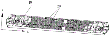
As shown in fig. 11 and 13, in the embodiment of the present invention, the underframe assembly includes two underframe side sills 20 arranged at intervals and a bolster 10 arranged between the two underframe side sills 20. The bolster 10 comprises a web structure 14, a centre pin 11 and a mounting bracket. Wherein the kingpin 11 is intended for connection with a bogie of a rail vehicle; the mounting bracket is connected with the web structure 14, the center pin 11 is arranged on the mounting bracket, the mounting bracket comprises a plurality of vertical plates 12, and the vertical plates 12 are arranged at intervals along the outer wall surface of the center pin 11.
In the application, the outer wall surface of the center pin 11 is provided with the vertical plates 12 to form the mounting frame, so that the connecting area of the center pin 11 and the web structure 14 is increased, and the connecting strength between the center pin 11 and the web structure 14 is improved. Compared with the prior art, the core pin and the sleeper beam that set up on the bogie pass through screw threaded connection, in this application, web structure 14 of core pin 11 and sleeper beam 10 is connected through additionally setting up the mounting bracket, utilize a plurality of risers 12 to increase the joint strength between mounting bracket and the core pin 11, then will be equipped with on the mounting bracket of core pin 11 is connected to web structure 14, the joint strength between core pin 11 and web structure 14 has been improved, and then the bulk strength of sleeper beam 10 has been improved, guaranteed in rail vehicle's operation process, core pin 11 can transmit the power and the moment that come from the bogie steadily, ensure rail vehicle's normal operating.
Specifically, as shown in fig. 39 and 40, on the underframe assembly of the railway vehicle, the joint of the bolster 10 and the center pin 11 is a stress concentration region on the underframe assembly. During the operation of the railway vehicle, it is necessary to secure the coupling strength between the center pin 11 and the bolster 10 so as to ensure that the center pin 11 can stably transmit the force and moment from the bogie. Therefore, the center pin 11 in the application is connected with the web structure 14 of the sleeper beam 10 through the mounting frame, the connection strength is good, the connection is firm, and the normal operation of the railway vehicle is ensured.
As shown in fig. 13, in the embodiment of the present invention, a plurality of vertical plates 12 are arranged in an X shape on the outer wall surface of the center pin 11, and each vertical plate 12 is welded to the outer wall surface of the center pin 11.
Specifically, the mounting bracket in the embodiment of the present application is composed of 4 vertical plates 12, and the 4 vertical plates 12 are arranged in an X shape on the outer wall surface of the center pin 11. Above-mentioned setting makes the intensity of mounting bracket higher, and 4 riser 12 play the supporting role to kingpin 11 simultaneously, have increased the joint strength between kingpin 11 and the mounting bracket, like this, when the mounting bracket assembly that follow-up will have kingpin 11 is to web structure 14 on, kingpin 11 is difficult for breaking away from with the mounting bracket, can be connected with the bogie better.
Furthermore, 4 vertical plates 12 are all welded to the outer wall surface of the center pin 11, and compared with the prior art in which the center pin is connected with the sleeper beam through bolts, the connecting mode of the connecting device is firmer. And 4 vertical plates 12 and the central pin 11 are welded to form a whole, so that the integral strength of the sleeper beam 10 is ensured.
Of course, in an alternative embodiment of the present invention, which is not shown in the drawings, the number of the vertical plates 12 of the mounting bracket is not limited to 4, and may be appropriately set according to the inner space of the body bolster 10.
In an embodiment of the invention, shown in figure 13, the bolster 10 comprises two web structures 14, with the mounting frame located between the two web structures 14.
In this application, the mounting bracket is located between two web structures 14, and the mounting bracket all is connected with two web structures 14 to the both ends that make the mounting bracket all receive fixedly, have increased the stability of mounting bracket, and then have guaranteed the stability that kingpin 11 is connected with web structure 14 of sleeper beam 10.
As shown in fig. 13, in the embodiment of the present invention, the bolster 10 further includes a plurality of rib plates 13, the web structure 14 includes two webs 141 arranged at intervals, and the plurality of rib plates 13 are arranged at intervals between the two webs 141.
Preferably, the two webs 141 of the web structure 14 in the present application are arranged at an angle, and the spacing between the two webs 141 decreases in a direction away from the mounting frame.
A plurality of rib plates 13 are provided between the two webs 141, and preferably, a plurality of rib plates 13 are provided in parallel between the two webs 141. The arrangement increases the structural strength of the sleeper beam 10, and the plurality of rib plates 13 can effectively share the acting force transmitted to the sleeper beam 10, so that the bearing capacity of the sleeper beam 10 is improved.
Of course, in an alternative embodiment not shown in the drawings of the present invention, the plurality of rib plates 13 may be disposed at an included angle between the two webs 141, and the specific arrangement may be selected according to the bearing condition of the sleeper beam 10.
As shown in fig. 13, in an embodiment of the present invention, the web structure 14 is connected to at least one upright 12 of the mounting bracket by at least one rib 13.
Specifically, the web structure 14 is connected to the two vertical plates 12 of the mounting frame through the rib plate 13 located at the outermost side, that is, the rib plate 13 closest to the mounting frame is connected to the two vertical plates 12, and the rib plate 13 is connected to the two webs 141 of the web structure 14.
Among the above-mentioned setting, be connected mounting bracket and web structure 14 through gusset 13, for with mounting bracket and web structure 14 lug connection, the mode of setting up of this application is connected the line between mounting bracket and the web structure 14, turn into the line face between riser 12 and gusset 13 and be connected, the line face between web 141 and the gusset 13 is connected, the joint strength between mounting bracket and the web structure 14 has been improved, the stability that the mounting bracket is connected with web structure 14 has been guaranteed, and then the stability of being connected between core pin 11 and the web structure 14 has been guaranteed.
As shown in fig. 13, in the embodiment of the present invention, at least one rib 13 of the plurality of ribs 13 is provided with a weight-reducing through-hole 132.
Preferably, each rib plate 13 is provided with a weight-reducing through hole 132.
On the premise of ensuring that the rib plate 13 can strengthen the strength of the sleeper beam 10, the weight of the rib plate 13 is reduced, so that the weight of the sleeper beam 10 is reduced, and the weight of the underframe assembly is reduced. Further, through setting up and subtracting heavy through-hole 132, can block the transmission of impact force when the automobile body receives the impact, avoid the impact force to cause the destruction to the rear end of automobile body, improved the security of automobile body.
Of course, in an alternative embodiment not shown in the drawings of the present application, the size of the rib plate 13 may be designed as needed, and the lightening through holes 132 may be provided only on a part of the rib plate 13 to secure the strength of the bolster 10 and lighten the weight of the bolster 10.
As shown in fig. 13 and 14, in the embodiment of the present invention, each web 141 is provided with a wire passing hole 142.
The underframe assembly of the railway vehicle is provided with a wiring harness, and in order to facilitate connection and penetration of the wiring harness, the web 141 is provided with a wiring hole 142 for the wiring harness to penetrate or penetrate.
Specifically, in the present application, the wire passing holes 142 on the two webs 141 of the web structure 14 are correspondingly arranged to facilitate the passing of the wire harness. Preferably, can wear to establish the pipeline that is used for the line on crossing wire hole 142, make the pencil wear to establish by in the pipeline, the storage of the pencil of being convenient for avoids causing the destruction of pencil because of the pencil exposes.
As shown in fig. 12, in the embodiment of the present invention, the bolster 10 further includes an upper cover plate 15 covering the web 141, the upper cover plate 15 is provided with a plurality of through holes 151, the rib plate 13 is provided with protrusions 131, and the protrusions 131 are engaged with the corresponding through holes 151.
Preferably, as shown in fig. 15, each rib plate 13 of the present application is provided with a protrusion 131, and the upper cover plate 15 is provided with a plurality of through holes 151 corresponding to the plurality of protrusions 131 one to one. Through the arrangement, after the upper cover plate 15 is covered on the web plate 141, the protrusions 131 on the rib plates 13 are in inserted fit with the through holes 151 on the upper cover plate 15, so that the upper cover plate 15 is connected with the rib plates 13, and thus, the upper cover plate 15 covers a cavity defined by the web plate structure 14 and the rib plates 13, and a box body structure of the sleeper beam 10 is formed.
Further, in order to ensure the connection strength between the upper cover plate 15 and the rib plate 13, after the protrusion 131 is inserted into and matched with the through hole 151, the matched part is welded, so that the connection strength between the upper cover plate 15 and the rib plate 13 is further ensured, and the overall strength of the sleeper beam 10 is ensured.
As shown in fig. 12, in the embodiment of the present invention, the upper cover plate 15 is provided with a first through hole 152, and one end of the center pin 11 passes through the first through hole 152.
The above arrangement ensures the cooperation between the center pin 11 and the upper cover plate 15, and the first through hole 152 serves to limit the center pin 11, thereby ensuring the pivotal connection between the center pin 11 and the bogie provided at the lower portion of the underframe assembly.
As shown in fig. 14, in the embodiment of the present invention, the sleeper beam 10 further includes a lower cover plate 16 disposed at a lower portion of the web 141, and the lower cover plate 16 is fixedly connected to each rib plate 13.
In the present application, the upper cover plate 15 and the lower cover plate 16 are correspondingly disposed, and the upper cover plate 15, the lower cover plate 16 and the web structure 14 cooperate together to form a box structure. Further, the lower cover plate 16 is fixedly connected with each rib plate 13, so that the connection stability of the rib plates 13 and the lower cover plate 16 is ensured.
Preferably, the webs 141 and the lower cover plate 16 are welded, the rib plates 13 and the webs 141 are welded, and the upper cover plate 15 and the rib plates 13 are welded and fixed after being inserted and matched, so that the sleeper beam 10 forms a stable whole, and the overall strength of the sleeper beam 10 is ensured.
Preferably, as shown in fig. 14, in the embodiment of the present invention, the lower cover plate 16 is provided with a second through hole 161, and the other end of the center pin 11 passes through the second through hole 161.
The above arrangement ensures that the kingpin 11 is connected to the bogie provided at the lower portion of the underframe assembly, thereby ensuring that the bolster 10 can transmit the force and moment transmitted from the bogie to the car body.
As shown in fig. 11 and 12, in the embodiment of the present invention, the bolster 10 further includes two inner side beams 17 disposed at intervals, and the two inner side beams 17 are connected to the two underframe side beams 20 in a one-to-one correspondence.
Two inner side beams 17 are provided at both ends of the body bolster 10 at intervals in the width direction of the underframe assembly. And, the two inner side beams 17 are respectively connected with the two underframe side beams 20 in a one-to-one correspondence to connect the bolster 10 and the underframe side beams 20.
Preferably, the inner edge beam 17 is welded to the chassis edge beam 20, so that the connection strength between the bolster 10 and the chassis edge beam 20 is ensured.
In an embodiment of the present invention, as shown in fig. 13, the inner sill 17 is connected to both webs 141 of at least one web structure 14.
In particular, in an embodiment of the invention, the bolster 10 includes two web structures 14, the two web structures 14 being located on either side of the mounting bracket. The inner edge beam 17 on the same side of the mounting frame is welded to both of the webs 141 of the web structure 14.
The arrangement enables the interior of the sleeper beam 10 to form a complete cavity, and the web 141 is connected with the inner edge beam 17 in a welding mode, so that the overall strength of the sleeper beam 10 is further guaranteed.
As shown in fig. 16 and 17, an embodiment of the present invention provides an undercarriage assembly for a rail vehicle. The underframe assembly of this embodiment includes two underframe boundary beams 20 that the interval set up and sets up a plurality of crossbeam assemblies 40 between two underframe boundary beams 20, and a plurality of crossbeam assemblies 40 set up along the length direction interval of underframe boundary beam 20, are equipped with connecting seat 21 on at least one underframe boundary beam 20, and at least one end of crossbeam assembly 40 is passed through connecting seat 21 and is connected with underframe boundary beam 20.
Specifically, connecting seat 21 and the face-to-face contact of crossbeam subassembly 40 in this application, and connecting seat 21 and chassis boundary beam 20 face-to-face contact, like this, turn into being connected between crossbeam subassembly 40 and connecting seat 21 with the relation of being connected between crossbeam subassembly 40 and chassis boundary beam 20, be connected between connecting seat 21 and the chassis boundary beam 20, and then for the line face contact between crossbeam subassembly 40 and the chassis boundary beam 20 among the prior art, turn into face-to-face contact through connecting seat 21, the joint strength between crossbeam subassembly 40 and the chassis boundary beam 20 has been increased, the intensity and the rigidity requirement of chassis subassembly have been guaranteed. Further, for beam assembly 40 among the prior art and chassis boundary beam 20 realize line face contact through welding or joint, the face contact in this application is connected more easily, has made things convenient for operating personnel to the equipment of chassis assembly, has improved assembly efficiency.
As shown in fig. 18 to 21, in the embodiment of the present invention, the underframe edge rail 20 includes a first flat plate 201, a vertical plate 202 and a second flat plate 203 which are connected in sequence, and the connecting seat 21 includes a first connecting plate 211, a second connecting plate 212 and a third connecting plate 213. The first connecting plate 211 is connected with the riser 202; the second connecting plate 212 and the first connecting plate 211 form an included angle, and the second connecting plate 212 is connected with the beam assembly 40; the third connecting plate 213 and the first connecting plate 211 and the second connecting plate 212 are both arranged at an included angle, and the third connecting plate 213 is connected with the first flat plate 201 or the second flat plate 203.
Specifically, connecting seat 21 in this application comprises three connecting plates, and arbitrary two are all connected perpendicularly, through setting up connecting seat 21, turn into being connected between crossbeam subassembly 40 and the chassis boundary beam 20 and be connected between crossbeam subassembly 40 and the connecting seat 21, be connected between connecting seat 21 and the chassis boundary beam 20, and then be connected the line between crossbeam subassembly 40 and the chassis boundary beam 20 among the prior art or the point connection, turn into the face between crossbeam subassembly 40 and the connecting seat 21 and be connected, the face between connecting seat 21 and the chassis boundary beam 20 is connected. Therefore, through the arrangement, the connection strength of the cross beam assembly 40 to the underframe edge beam 20 is improved, and the rigidity requirement of the underframe assembly of the railway vehicle is ensured.
Preferably, in the embodiment of the present invention, when the connecting base 21 is used to connect the first cross member 41 and the underframe side member 20, the first connecting plate 211 is welded to the vertical plate 202, and the third connecting plate 213 is welded to the first flat plate 201; when the connecting base 21 is used for connecting the second cross beam 42 and the underframe edge beam 20, the first connecting plate 211 is welded to the vertical plate 202, and the third connecting plate 213 is welded to the second flat plate 203.
In the above arrangement, the welding connection mode is simple, the strength is high, and the connection strength between the connection seat 21 and the underframe edge beam 20 is ensured.
Preferably, the second connecting plate 212 is welded to the beam assembly 40.
The connection strength between the beam assembly 40 and the connecting seat 21 is guaranteed through the arrangement, the connecting seat 21 and the underframe boundary beam 20 are also connected in a welding connection mode, the connection strength between the beam assembly 40 and the underframe boundary beam 20 is further guaranteed, and the strength and rigidity requirements of the underframe assembly are met.
Preferably, the first connecting plate 211, the second connecting plate 212 and the third connecting plate 213 in this application are integrally formed, and the above arrangement ensures the strength of the connecting seat 21.
As shown in fig. 19, in the present application, a lightening hole 214 is further formed on connecting seat 21, and the weight of the chassis assembly is reduced by the lightening hole 214, and the forming of connecting seat 21 is facilitated.
As shown in fig. 16 and 17, in an embodiment of the present invention, at least one beam assembly 40 of the plurality of beam assemblies 40 includes a first beam 41 and a second beam 42. The two opposite ends of the first cross beam 41 are respectively connected with the two underframe side beams 20 correspondingly, and the second cross beam 42 is arranged corresponding to the first cross beam 41 in the height direction of the underframe side beams 20.
Specifically, as shown in fig. 10, in the height direction of the undercarriage side member 20, the first cross member 41 and the second cross member 42 are provided correspondingly, and the second cross member 42 is provided below the first cross member 41.
Further, a plurality of first cross members 41 and a plurality of second cross members 42 are disposed between the two underframe edge beams 20 along the length direction of the underframe assembly. Alternatively, the length of the first cross member 41 is equal to the distance between the two oppositely disposed undercarriage side members 20.
In this application, set up crossbeam subassembly 40 into the cooperation structure of first crossbeam 41 and second crossbeam 42, process a plurality of first crossbeams 41 of the same structure and a plurality of second crossbeam 42 of the same structure in process of production, then assemble first crossbeam 41 and second crossbeam 42 according to the structural requirement of chassis subassembly, realized the assembly process modularization, improved production efficiency.
As shown in fig. 16 and 18, in the embodiment of the present invention, two connecting seats 21 are provided on at least one of the underframe side sills 20, and the first cross member 41 and the second cross member 42 are connected to the underframe side sills 20 through the corresponding connecting seats 21, respectively.
In the present application, the first cross member 41 and the second cross member 42 are connected to the chassis side member 20 by the connecting base 21.
Preferably, the size of the connection seat 21 may be adjusted according to the sectional size of the first cross member 41 and the second cross member 42 to be matched with the sectional size of the first cross member 41 or the second cross member 42.
As shown in fig. 16, in the embodiment of the present invention, the second beam 42 includes a plurality of beam segments connected in series, at least one of the plurality of beam segments is connected to one of the two undercarriage sills 20, and at least another one of the plurality of beam segments is connected to another one of the two undercarriage sills 20.
Specifically, the second cross beam 42 in the present application includes three cross beam sections connected in sequence, one end of one cross beam section located at the outermost side is connected to one of the chassis boundary beams 20 through the connecting seat 21, and the other end is connected to the cross beam section located at the middle of the second cross beam 42; one end of the other cross beam section located at the outermost side is connected to the other underframe edge beam 20 by a connecting base 21. Therefore, two of the three cross beam sections located at the outermost side are correspondingly connected with the two underframe edge beams 20, and the cross beam section located at the middle part is connected with the cross beam sections located at the two ends.
As shown in fig. 20, in the embodiment of the present invention, the underframe assembly comprises a plurality of second cross beams 42, and a hooking portion 421 is provided on a side of at least one second cross beam 42 away from the first cross beam 41.
In this application, because the equipment of chassis subassembly bottom can not with chassis subassembly welded connection, consequently, through setting up hook portion 421, realized that the hook of chassis subassembly and bottom equipment is connected, satisfied the connection requirement.
Preferably, the hooking portion 421 and the second beam 42 are of an integrally formed structure.
As shown in fig. 16 and 17. In an embodiment of the present invention, the undercarriage assembly further comprises a center sill 30 disposed between the two undercarriage side sills 20, the center sill 30 extending along a length of the undercarriage side sills 20.
Specifically, the chassis assembly of this application includes two well roof beams 30 that the interval set up, and two well roof beams 30 extend along the length direction of chassis boundary beam 20, and two well roof beams 30 cooperate with chassis boundary beam 20 to satisfy the ascending intensity requirement of length direction of chassis assembly.
Of course, in an alternative embodiment of the present invention, not shown in the drawings, the number of center sills 30 is not limited to two, and may be set according to the space and strength and rigidity requirements of the underframe assembly.
Preferably, as shown in fig. 16 and 17, in the embodiment of the present invention, the center sill 30 is disposed at an angle to each cross member assembly 40.
In the present application, each cross member assembly 40 is disposed perpendicular to the center sill 30, and each cross member assembly 40 is disposed perpendicular to the two undercarriage side sills 20. The arrangement enables the underframe assembly to form a structure similar to a grid, further improves the strength and rigidity of the underframe assembly, and ensures the installation and normal operation of equipment on the underframe assembly.
As shown in fig. 16, in the embodiment of the present invention, the underframe assembly further includes a cover plate 35 disposed on the center sill 30, and a ventilation duct is formed between the cover plate 35 and the center sill 30.
Specifically, the ventilation air duct is arranged on the underframe assembly, and an air supply outlet and an air outlet communicated with the environment in the vehicle are arranged on the ventilation air duct. The cover plate 35 cooperates with the center sill 30 to form a ventilation duct, thereby forming a longitudinal sill along the length of the underframe assembly, which cooperates with the underframe side sills 20 to carry weight from the car body structure and the in-car devices, improving the load bearing capacity of the rail car.
In the present application, at least one beam assembly 40 of the plurality of beam assemblies 40 includes only the first beam 41. Second crossbeam 42 in this application plays the supporting role to apron 35, and the technician can suitably set up the quantity of second crossbeam 42 as required, on the basis of the intensity of guaranteeing the underframe assembly, the quantity of second crossbeam 42 can suitably reduce, need not set up with first crossbeam 41 one-to-one. And the reduction of the number of the second cross beams 42 can reduce the weight of the underframe assembly, thereby achieving the effect of light weight.
In the present invention and the embodiment of the present invention, as shown in fig. 22, the longitudinal direction of the chassis assembly is referred to as the X direction, and the width direction of the chassis assembly is referred to as the Y direction.
As shown in fig. 22 and 23, an embodiment of the present invention provides an undercarriage assembly for a railway vehicle. The undercarriage assembly includes an undercarriage edge rail 20 and a cross-member assembly 40. The number of the underframe edge beams 20 is two, and the two underframe edge beams 20 are arranged at intervals; the beam assemblies 40 are arranged between the two underframe edge beams 20, the number of the beam assemblies 40 is multiple, and the beam assemblies 40 are arranged at intervals along the length direction of the underframe edge beams 20; in the height direction of the underframe edge beam 20, at least one cross beam assembly 40 comprises a first cross beam 41 and a second cross beam 42 arranged below the first cross beam 41, the first cross beam 41 and the second cross beam 42 form an installation cavity, and a part of a floor 43 of the railway vehicle penetrates through the installation cavity.
In this application, the beam assembly 40 includes first crossbeam 41 and second crossbeam 42, in the direction of height of chassis boundary beam 20, first crossbeam 41 and second crossbeam 42 set gradually, thereby first crossbeam 41 and second crossbeam 42 all are located the space that two chassis boundary beams 20 formed, and form the installation cavity between first crossbeam 41 and the second crossbeam 42, and then when installing floor 43 to the installation cavity of beam assembly 40, the height that highly is less than the height of the upper surface of chassis boundary beam 20 of the upper surface of floor 43, for directly laying the floor in the top of crossbeam among the prior art, in this application under the circumstances of guaranteeing not to increase chassis assembly height, the space of vehicle inside has been increased. Further, at least part of the floor 43 is arranged in the mounting cavity in a penetrating mode, and the floor 43 is clamped between the first cross beam 41 and the second cross beam 42, so that the mounting strength of the floor 43 is improved.
As shown in fig. 23 and 24, in the embodiment of the present invention, the first cross member 41 includes a U-shaped beam 411 and a connection beam 412 connected to the U-shaped beam 411, and the connection beam 412 is used to connect to the floor 43.
Specifically, the U-shaped beam 411 of the present application includes two vertical sections opposite to each other and a horizontal section connecting the two vertical sections, wherein one of the two vertical sections is connected to the connection beam 412, and the vertical section has a height dimension larger than that of the other vertical section.
Through the arrangement, the strength of the U-shaped beam 411 is good, and the strength requirement of the underframe assembly of the railway vehicle is met. Furthermore, the connecting beam 412 is a flat plate structure, and the connecting beam 412 is in surface-to-surface contact with the floor 43, so that the connecting strength between the first cross beam 41 and the floor 43 is improved.
Specifically, in the embodiment of the present invention, the U-shaped beam 411 and the connecting beam 412 are integrally formed.
The whole strength of the first cross beam 41 is guaranteed through the arrangement, the processing is convenient, and the whole performance of the first cross beam 41 is good.
Of course, in an alternative embodiment of the present invention, which is not shown, the U-shaped beam 411 and the connecting beam 412 may be provided separately, as long as the connection strength between the U-shaped beam 411 and the connecting beam 412 can be ensured.
As shown in fig. 23 and 25, in the embodiment of the present invention, the cross-sectional shape of the second cross member 42 in the width direction of the underframe assembly is Z-shaped.
The arrangement enables the strength of the second cross beam 42 to be high, and compared with the cross beam in the prior art which is generally C-shaped, the Z-shaped second cross beam 42 of the present application can better meet the strength and rigidity requirements of the underframe assembly of the railway vehicle.
As shown in fig. 25, in the embodiment of the present invention, the second cross member 42 includes a first horizontal beam 422, a vertical beam 423, and a second horizontal beam 424 connected in sequence, the first horizontal beam 422 and the second horizontal beam 424 are respectively located at two sides of the vertical beam 423, and the first horizontal beam 422 is configured to be connected to a side of the floor 43 away from the first cross member 41.
In the present application, the first horizontal beam 422 and the second horizontal beam 424 are disposed on two sides of the vertical beam 423, and a connection portion where the first horizontal beam 422 is connected to the floor 43 is in surface-to-surface contact, so that the connection strength between the first horizontal beam 422 and the floor 43 is good.
Preferably, in the embodiment of the present invention, the first horizontal beam 422, the vertical beam 423, and the second horizontal beam 424 are an integrally formed structure.
The overall strength of the first cross beam 41 is guaranteed through the arrangement, the processing is convenient, and the integrity of the first cross beam 41 is good.
As shown in fig. 25, in the embodiment of the present invention, the second cross beam 42 is provided with a wire passing groove 425, and the wire passing groove 425 penetrates through the second horizontal beam 424 and extends to the vertical beam 423.
Specifically, the lower part of the underframe assembly can be passed through by the wiring harness, and since the second cross beam 42 is located below the floor 43, the wiring groove 425 is arranged on the second cross beam 42, so that the wiring harness can be conveniently penetrated out of the wiring groove 425, the wiring of the rail vehicle is facilitated, and the wiring harness is convenient to store. Furthermore, the wiring harness is accommodated in the wiring groove 425, so that the wiring harness can be prevented from occupying the space below the underframe assembly, the structure of the underframe assembly is compact, and the integrity is good.
Preferably, in the embodiment of the present invention, the floor panel 43 is connected to the first cross member 41 by welding, and the floor panel 43 is connected to the second cross member 42 by welding.
The arrangement ensures the connection strength between the floor 43 and the beam assembly 40, and the connecting beam 412 of the first beam 41 is in surface-to-surface contact with the floor 43, and the first horizontal beam 422 of the second beam 42 is in surface-to-surface contact with the floor 43, so that the welding is facilitated. Further, the floor 43 is sandwiched between the first cross member 41 and the second cross member 42, the second cross member 42 supports the floor 43, and the floor 43 is firmly installed.
Preferably, in the embodiment of the present invention, the floor panel 43 is a corrugated panel. The corrugated plate has good strength, and the use strength of the floor 43 is ensured.
As shown in fig. 22, in the embodiment of the present invention, opposite ends of the first cross member 41 are respectively disposed corresponding to the two undercarriage side members 20 in the width direction of the undercarriage assembly, and the distance between the two ends of the first cross member 41 is less than or equal to the distance between the two undercarriage side members 20.
Preferably, opposite ends of the first cross member 41 in the present invention are in abutting contact with the two undercarriage side members 20, respectively. The whole width of chassis subassembly has been guaranteed in the aforesaid setting, and first crossbeam 41 is connected with two chassis boundary beam 20 butt, except that second crossbeam 42 to the supporting role of first crossbeam 41, also can play the supporting role to first crossbeam 41 with chassis boundary beam 20 that first crossbeam 41 is connected, further guaranteed the joint strength of first crossbeam 41 with chassis boundary beam 20, can effectively support the structure and the device that set up on chassis subassembly upper portion.
Further, the upper surface of the first cross member 41 is disposed flush with the upper surface of the undercarriage side member 20.
The installation of chassis subassembly upper portion equipment is convenient for in above-mentioned setting, and the roughness is better, and equipment fixing is firm. Furthermore, the arrangement enables the upper surface of the first cross beam 41 and the upper surface of the underframe edge beam 20 to form a plane grid structure, so that the support strength is good, and the requirements of underframe assemblies on strength and rigidity are met.
In the present invention and the embodiment of the present invention, as shown in fig. 26, the longitudinal direction of the chassis assembly is referred to as the X direction, and the width direction of the chassis assembly is referred to as the Y direction.
As shown in fig. 26 and 29, an embodiment of the present invention provides an undercarriage assembly for a rail vehicle. The undercarriage assembly of this embodiment includes two undercarriage side rails 20 and a center rail 30 spaced apart. The center sill 30 of this embodiment is disposed between two underframe side sills 20, the center sill 30 extends in the longitudinal direction of the underframe side sills 20, and the cross-sectional shape of the center sill 30 is Z-shaped in the width direction of the railway vehicle.
In the present application, the cross-sectional shape of the center sill 30 is Z-shaped, so that the structural strength of the center sill 30 is better, and the length extension directions of the center sill 30 and the underframe side sills 20 are the same, so that the center sill 30 and the underframe side sills 20 can be simultaneously used as a support beam in the length direction of the underframe assembly. Therefore, through the arrangement, the strength requirement of the middle beam 30 is guaranteed, the overall strength and rigidity of the underframe assembly are improved, and compared with the middle beam with the C-shaped cross section in the prior art, the middle beam 30 is higher in strength and better in supporting effect.
As shown in fig. 30, in the embodiment of the present invention, the center sill 30 includes a first horizontal section 31, a vertical section 32, and a second horizontal section 33 connected in sequence, and the first horizontal section 31 and the second horizontal section 33 are respectively disposed at opposite sides of the vertical section 32.
Specifically, first horizontal segment 31 and second horizontal segment 33 in this application set up respectively in the relative both sides of vertical segment 32, and the bearing capacity transmits other parts through vertical segment and second horizontal segment, and the pressure when well roof beam 30 bearing can obtain effectual dispersion, has improved the structural strength of well roof beam 30.
Further, in the embodiment of the present invention, the underframe assembly comprises two opposite center sills 30, and the first horizontal sections 31 of the two center sills 30 are disposed close to each other in the width direction of the underframe assembly, so that when the underframe assembly is subjected to a compressive force, the two center sills 30 can share the compressive force from the upper part of the underframe assembly, and the strength and rigidity requirements of the underframe assembly are met.
Preferably, in the embodiment of the present invention, one end of the first horizontal segment 31 away from the vertical segment 32 is provided with a bending portion 311. The provision of the bent portion 311 further improves the structural strength of the center sill 30.
Further, as shown in fig. 29 and 30, the bent portion 311 is bent toward the side where the second horizontal section 33 is located. By providing the bending portion 311, the end of the first horizontal segment 31 extends downward, so that the problem that the installer is easily scratched when performing an assembling process due to the sharpness of the end of the first horizontal segment 31 is avoided.
Preferably, the first horizontal segment 31, the vertical segment 32 and the second horizontal segment 33 are of an integrally formed structure. The arrangement ensures that the overall structure of the middle beam 30 has high strength, meets the requirements of strength and rigidity of the underframe assembly, has good integrity of the middle beam 30, is convenient to process and simplifies the assembly process.
As shown in fig. 26 and 27, in the embodiment of the present invention, the rail vehicle further includes a floor panel 43, the floor panel 43 is provided on the center sill 30 in a covering manner, and the floor panel 43 is connected to each of the underframe side sills 20; the underframe assembly further comprises a cover plate 35, the cover plate 35 is connected with the center sill 30, the center sill 30 is positioned between the floor 43 and the cover plate 35, and the floor 43, the cover plate 35 and the center sill 30 jointly enclose a main air duct of the railway vehicle.
Specifically, the undercarriage assembly shown in fig. 26 is a schematic view of the structure as viewed from the bottom of the rail vehicle looking up. The center sill 30 in this application is arranged between two underframe boundary beams 20, the floor 43 is arranged above the two center sills 30, and along the width direction of the underframe assembly, the two ends of the floor 43 are connected with each underframe boundary beam 20, thereby the center sill 30 and the underframe boundary beams 20 simultaneously play a role in supporting the floor 43, and the connection strength of the floor 43 is ensured.
Further, as shown in fig. 29, a cover plate 35 is provided at a lower portion of the two center sills 30, and the cover plate 35 is used to cover a space between the two center sills 30, so that the cover plate 35, the floor 43 and the center sill 30 together form a main duct on the underframe assembly.
Through the arrangement, the main air duct on the underframe assembly is convenient for air circulation, the main air duct and the underframe boundary beam 20 bear pressure from the upper part of the underframe assembly, and the floor 43 and the cover plate 35 of the main air duct are both of flat plate structures, so that the pressure-bearing area is increased, the pressure is effectively dispersed, and the pressure-bearing capacity of the underframe assembly is improved.
Preferably, in the embodiment of the present invention, the floor panel 43 is a corrugated panel, and the cover panel 35 is a corrugated panel.
In the present application, the direction in which the corrugations of the floor panel 43 and the cover panel 35 extend coincides with the direction in which the length of the undercarriage side rails 20 extends. Because rail vehicle's length is far greater than rail vehicle's width, rail vehicle's the ascending intensity requirement of length direction is higher, consequently, the intensity of floor 43 and apron 35 has been guaranteed in the setting of buckled plate, makes main wind channel play the supporting role with chassis boundary beam 20 together in rail vehicle's length direction, has further improved the intensity of chassis subassembly.
Preferably, in the embodiment of the present invention, the floor panel 43 is welded to the center sill 30, and the cover panel 35 is also welded to the center sill 30. Moreover, spot welding sealants are arranged at the joint of the center sill 30 and the floor 43 and the joint of the center sill 30 and the cover plate 35 to seal the gap at the joint, so that the connection strength between the center sill 30 and the floor 43 and between the cover plates 35 is further increased.
As shown in fig. 28, in the embodiment of the present invention, the cover plate 35 includes a first cover plate 351 and a second cover plate 352 spaced apart from the first cover plate 351, and the space between the first cover plate 351 and the second cover plate 352 forms an air inlet communicated with the main air duct.
Specifically, in the length direction of the underframe side frame 20, a first cover plate 351 and a second cover plate 352 are arranged at intervals to form an air inlet communicated with the main air duct. The above arrangement ensures the air source of the main air duct on the chassis assembly. Further, be equipped with a plurality of air outlets on floor 43, the air that gets into the main air duct by the air intake can get into rail vehicle's inside by the air outlet, has guaranteed the inside circulation of air of rail vehicle, has improved user experience.
As shown in fig. 28, in the embodiment of the present invention, the bottom frame assembly further includes a plurality of reinforcing ribs 353, and the plurality of reinforcing ribs 353 are disposed on the cover plate 35 at intervals.
Preferably, the reinforcing ribs 353 are provided on the cover plate 35 at intervals in the length direction of the underframe edge beam 20. The reinforcing ribs 353 effectively improve the strength of the cover plate 35 in the width direction, and are matched with the longitudinal corrugations of the corrugated plates, so that the strength and the rigidity of the cover plate 35 meet the requirements of the underframe assembly.
Further, a reinforcing rib 353 is provided on the cover plate 35 by welding.
As shown in fig. 26, in the embodiment of the present invention, the underframe assembly further includes a plurality of cross beam assemblies 40 disposed between the two underframe edge beams 20, the plurality of cross beam assemblies 40 are disposed at intervals along the length direction of the underframe edge beams 20, and the center sill 30 is disposed at an angle to each cross beam assembly 40.
In the present application, each cross member assembly 40 is preferably disposed perpendicular to the center sill 30, and each cross member assembly 40 is also disposed perpendicular to the two undercarriage side sills 20. The arrangement enables the underframe assembly to form a structure similar to a grid, further improves the strength and rigidity of the underframe assembly, and ensures the installation and normal operation of equipment on the underframe assembly.
As shown in fig. 27 and 28, in the embodiment of the present invention, a plurality of reinforcing members 34 are provided on the center sill 30, and the plurality of reinforcing members 34 and the plurality of cross member assemblies 40 are provided in a one-to-one correspondence.
The arrangement ensures the connection strength of the middle beam 30 and the cross beam assembly 40, and further ensures the strength and rigidity of the underframe assembly.
Preferably, the reinforcement 34 includes a first reinforcement structure 341 and a second reinforcement structure 342, the first reinforcement structure 341 and the second reinforcement structure 342 are disposed at an included angle, and the first reinforcement structure is disposed on the vertical section 32 of the center sill 30.
In the present application, as shown in fig. 31, the reinforcing member 34 is an L-shaped angle iron, and the L-shaped angle iron includes a first reinforcing section and a second reinforcing section vertically connected to the first reinforcing section, wherein the first reinforcing section forms the first reinforcing structure 341, and the second reinforcing section forms the second reinforcing structure 342. The first reinforcement section of L shape angle bar and the vertical section 32 welded connection of center sill 30, the second reinforcement section and the crossbeam subassembly 40 welded connection of L shape angle bar to be in the same place center sill 30 and crossbeam subassembly 40 connection, and the joint strength between center sill 30 and the crossbeam subassembly 40 is good.
Traditional ground rail vehicle's main wind channel is installed on the roof more, and in this application, rail vehicle's main wind channel arranges on the chassis subassembly, and more equipment under the car need be hung to rail vehicle's the lower part of chassis subassembly, does not have unnecessary space, consequently, under the sufficient prerequisite of intensity of guaranteeing the chassis subassembly, utilizes well roof beam 30, floor 43 and the apron 35 of chassis subassembly, forms the main wind channel, has solved the problem of setting up of main wind channel.
Specifically, the main air duct is formed by connecting the center sill 30, the floor 43 and the cover plate 35 of the underframe assembly by spot welding; secondly, the cross-sectional shape of the centre sill 30 of the underframe assembly is Z-shaped, and the front end and the rear end of the centre sill 30 are in plug-in connection with the sleeper inner longitudinal beam, so that the underframe assembly forms a whole, and the strength of the underframe assembly is improved.
The center sill 30 of the present invention is disposed in the middle of the undercarriage assembly and provides longitudinal support in cooperation with the undercarriage side sills 20. The cross section of the middle beam 30 is Z-shaped, the bearing capacity is strong, the front end part and the rear end part of the middle beam 30 are connected with the sleeper inner longitudinal beam of the end underframe, so that the underframe assembly forms an integral structure, and the floor 43 and the cover plate 35 are respectively welded and connected with the two middle beams 30 to form a hollow cavity; be equipped with the air outlet on floor 43, form the air intake between first apron 351 and the second apron 352, air intake and air outlet all are linked together with the main air duct, have guaranteed the inside circulation of air of rail vehicle, have improved user experience.
As shown in fig. 32, 33 and 35, an embodiment of the present invention provides an undercarriage assembly of a railway vehicle. The undercarriage assembly of this embodiment includes two undercarriage side rails 20 and a tube running structure 22 spaced apart. The side of the at least one underframe edge rail 20 facing the car body of the rail vehicle is provided with a pipe running structure 22, wherein the pipe running structure is a pipe running channel provided on the underframe edge rail 20.
In this application, owing to set up on chassis boundary beam 20 and passed through tubular structure 22 to the pipeline that makes to pass the below by rail vehicle top or pass to the top by rail vehicle below can wear out by tubular structure 22, with the pipeline wear to establish on realizing rail vehicle's the chassis subassembly, and then avoid additionally setting up the structure that is used for the pipeline to wear to establish on the chassis subassembly, saved the space on the chassis subassembly, made whole chassis subassembly compact structure. Therefore, through the arrangement, the effective space of the underframe assembly is effectively utilized, the pipeline on the underframe assembly is convenient to wear, and the overall structure of the underframe assembly is simplified.
Preferably, the pipe passing structure 22 in the present application is particularly suitable for the threading of air conditioning pipes, and the pipe passing channel in the present application is a pipe passing hole or a pipe passing groove provided on the underframe edge beam 20. Of course, in alternative embodiments of the invention not shown, the pipe-over-structure 22 may also be adapted for the threading of other pipes or lines.
As shown in fig. 33 and 35, in the embodiment of the present invention, the underframe assembly further includes a first reinforcing member 23, the first reinforcing member 23 is located on the side of the pipe structure 22 away from the car body, and the first reinforcing member 23 is connected to a part of the underframe side sill 20.
Specifically, in the present application, the first reinforcement 23 is provided below the pipe structure 22 to reinforce the outer periphery of the pipe structure 22. The above arrangement ensures structural strength around the pipe structure 22 and thus the underframe edge beam 20. Therefore, the underframe edge beam 20 of the present application not only facilitates the pipe on the underframe assembly to be penetrated, but also ensures the strength of the underframe edge beam 20 itself.
As shown in fig. 37, in an embodiment of the present invention, the undercarriage sill 20 includes a first plate 201, a riser 202, and a second plate 203. The first plate 201 and the second plate 203 are arranged at intervals, and the riser 202 is connected with the first plate 201 and the second plate 203.
In the present application, the cross-sectional shape of the undercarriage side rails 20 is U-shaped along the length of the undercarriage side rails 20. The structure enables the strength of the chassis boundary beam 20 to be higher, improves the bearing capacity of the chassis boundary beam 20, and meets the strength requirement of the railway vehicle on the chassis boundary beam 20. And above-mentioned structure weight is lighter, has alleviateed the weight of whole chassis subassembly, has realized the lightweight of chassis subassembly.
Further, the pipe passing structure 22 in the present application is disposed on the first plate 201, so as to facilitate the pipe passing on the bottom frame assembly.
Preferably, as shown in fig. 35, the first reinforcement 23 is fixedly attached to the riser 202.
The first reinforcing members 23 are welded to the risers 202, and the structural strength of the underframe edge beam 20 in the height direction is enhanced.
As shown in fig. 35, in the embodiment of the present invention, the first reinforcement 23 includes a first reinforcement plate 231 and a second reinforcement plate 232 connected to the first reinforcement plate 231, wherein an included angle is formed between the first reinforcement plate 231 and the second reinforcement plate 232, and the first reinforcement plate 231 is fixedly connected to the riser 202.
In this application, the first reinforcing plate 231 and the second reinforcing plate 232 are vertically disposed, the first reinforcing plate 231 is welded to the riser 202, the second reinforcing plate 232 is parallel to the first plate 201, and a space is provided between the second reinforcing plate 232 and the first plate. Through the above arrangement, after the pipeline on the underframe assembly passes through the pipe structure 22, the second reinforcing plate 232 can support the pipeline, so that the pipeline can be conveniently penetrated on the underframe assembly, and the second reinforcing plate 232 can also be conveniently used for constraining the pipeline, so that the pipeline is arranged according to a preset path.
Preferably, as shown in FIG. 37, in an embodiment of the present invention, the width dimension L1 of the first panel 201 is greater than the width dimension L2 of the second panel 203.
The pipe structure 22 in this application is seted up on first flat board 201, and the width dimension L1 of first flat board 201 is greater than the width dimension L2 of second flat board 203, has reserved for the pipe structure 22 and has set up the space, and has guaranteed to set up behind the pipe structure 22, the intensity of first flat board 201, and then guarantee chassis boundary beam 20's structural strength.
As shown in fig. 32 to 34, in the embodiment of the present invention, at least one of the underframe side sills 20 is further provided with a plurality of second reinforcements 28, and the plurality of second reinforcements 28 are arranged at intervals in the length direction of the underframe side sill 20.
In this application, in the length direction of chassis boundary beam 20, a plurality of second reinforcement 28 intervals set up to play the reinforcement effect to chassis boundary beam 20, guarantee chassis boundary beam 20's structural strength.
As shown in fig. 33 and 36, in the embodiment of the present invention, the chassis assembly further includes a main air duct and a branch air duct communicated with the main air duct, and the chassis frame 20 is provided with the ventilation opening 24 communicated with the branch air duct.
Specifically, the underframe assembly includes a center sill disposed between two underframe edge beams 20, with cover plates disposed on the two center sills, the cover plates, the two center sills, and a floor disposed on the underframe assembly forming a main air duct. The main air duct in this application is arranged along the length direction of the chassis boundary beam 20, the branch air duct is perpendicular to the main air duct, and the chassis boundary beam 20 is provided with a vent 24 communicated with the branch air duct.
The provision of the vents 24 ensures that the air supply to the main duct and the branch duct of the chassis assembly is ensured. The air entering the branch air duct from the ventilation opening 24 can circulate in the main air duct and the branch air duct, so that the air circulation in the railway vehicle is ensured, and the user experience is improved.
Preferably, in the embodiment of the present invention, the chassis assembly further includes a ventilation duct, a branch duct is enclosed by an inner wall surface of the ventilation duct, a support seat 25 is disposed on the chassis boundary beam 20 corresponding to the ventilation opening 24, and the ventilation duct is connected to the support seat 25.
A wind channel in this application is formed by the air pipe of setting on the chassis subassembly, and the both ends of air pipe are taken and are established on supporting seat 25 to make a wind channel and vent 24 be linked together, and then guaranteed the circulation of air in the wind channel.
As shown in fig. 36, in the embodiment of the present invention, the support base 25 includes a first side plate 251, a second side plate 252, and a third side plate 253. First margin 251 is connected to riser 202; the second side plate 252 is arranged at a distance from the first side plate 251; a third edge plate 253 connects the first edge plate 251 and the second edge plate 252, and a ventilation duct is provided on the third edge plate 253.
Further, the first side plate 251, the second side plate 252 and the third side plate 253 are connected to form the supporting base 25, so that the stability of supporting the ventilation duct is ensured.
Preferably, the third plate 253 in the present application is disposed in parallel with the first plate 201. The arrangement ensures that the ventilation pipeline is stably installed on the supporting seat.
Further, the cross-sectional shape of the support base 25 is U-shaped along the width direction of the underframe assembly.
As shown in fig. 32 and 33, in the embodiment of the present invention, the underframe assembly further includes a plurality of cross beam assemblies 40 disposed between the two underframe edge beams 20, the plurality of cross beam assemblies 40 are disposed at intervals along the length direction of the underframe edge beams 20, at least one of the underframe edge beams 20 is provided with a connecting seat 21, and at least one end of the cross beam assembly 40 is connected to the underframe edge beam 20 through the connecting seat 21.
Specifically, connecting seat 21 and the face-to-face contact of crossbeam subassembly 40 in this application, and connecting seat 21 and chassis boundary beam 20 face-to-face contact, like this, turn into being connected between crossbeam subassembly 40 and connecting seat 21 with the relation of being connected between crossbeam subassembly 40 and chassis boundary beam 20, be connected between connecting seat 21 and the chassis boundary beam 20, and then for the line face contact between crossbeam subassembly 40 and the chassis boundary beam 20 among the prior art, turn into face-to-face contact through connecting seat 21, the joint strength between crossbeam subassembly 40 and the chassis boundary beam 20 has been increased, the intensity and the rigidity requirement of chassis subassembly have been guaranteed. Further, for beam assembly 40 among the prior art and chassis boundary beam 20 realize line face contact through welding or joint, the face contact in this application is connected more easily, has made things convenient for operating personnel to the equipment of chassis assembly, has improved assembly efficiency.
As shown in fig. 34 and 38, in the embodiment of the present invention, the connection holder 21 includes a first connection plate 211, a second connection plate 212, and a third connection plate 213. Wherein, the first connecting plate 211 is connected with the vertical plate 202; the second connecting plate 212 and the first connecting plate 211 form an included angle, and the second connecting plate 212 is connected with the beam assembly 40; the third connecting plate 213 and the first connecting plate 211 and the second connecting plate 212 are both arranged at an included angle, and the third connecting plate 213 is connected with the first flat plate 201 or the second flat plate 203.
Connecting seat 21 in this application comprises three connecting plates, arbitrary two equal perpendicular connections, through setting up connecting seat 21, turn into being connected between beam assembly 40 and the chassis boundary beam 20 and be connected between beam assembly 40 and connecting seat 21, be connected between connecting seat 21 and the chassis boundary beam 20, and then be connected or the point connection with the line between beam assembly 40 and the chassis boundary beam 20 among the prior art, turn into the face between beam assembly 40 and the connecting seat 21 and be connected, the face between connecting seat 21 and the chassis boundary beam 20 is connected. Therefore, through the arrangement, the connection strength of the cross beam assembly 40 to the underframe edge beam 20 is improved, and the rigidity requirement of the underframe assembly of the railway vehicle is ensured.
Further, as shown in fig. 34, connecting seat 21 and second reinforcement 28 cooperate the setting on chassis boundary beam 20, form the reinforcement and concentrate the district to when hoist and mount chassis subassembly or whole rail vehicle, can concentrate the district at the reinforcement and hoist, because the reinforcement concentrates district intensity higher, difficult emergence is out of shape at hoist and mount in-process, has guaranteed that the wholeness of whole chassis subassembly is good.
In the embodiment of the present invention, as shown in fig. 33, the undercarriage side rails 20 are further provided with drain holes 26.
Due to the arrangement of the drain holes 36, accumulated water on the underframe assembly can be drained conveniently, and the underframe assembly is prevented from being corroded due to the accumulated water.
Further, a wire passing through hole is further formed in the underframe edge beam 20, so that a wire harness on the underframe assembly can pass through the wire passing through hole.
As shown in fig. 41 and 42, in the embodiment of the present invention, the side wall assembly 70 includes a side wall body 701 and a plurality of side wall pillars 710, the plurality of side wall pillars 710 are all connected to the side wall body 701, and the plurality of side wall pillars 710 are arranged at intervals along the length direction of the side wall body 701; in the length direction of the side wall body 701, an auxiliary air duct of the rail vehicle is formed between at least two side wall columns 710 and the side wall body 701.
In the application, the side wall body 701 and the side wall upright column 710 of the side wall assembly 70 are utilized to form the auxiliary air duct of the railway vehicle, and compared with the prior art that an air duct structure needs to be additionally arranged, and the additionally arranged air duct structure is welded or riveted to the outside of the side wall assembly 70 or the inside of the side wall assembly 70, the auxiliary air duct of the application is formed on the side wall assembly 70 and does not protrude out of the side wall assembly 70, so that the space outside or inside the railway vehicle cannot be additionally occupied, the integrity of the railway vehicle is ensured, and the problem that the air resistance or the space inside the railway vehicle is occupied in the running process of the railway vehicle due to the additionally arranged air duct structure is avoided; the sidewall body 701 and the sidewall pillars 710 are both members of the sidewall assembly 70, and the weight of the sidewall assembly 70 is not increased by the above arrangement. Therefore, the auxiliary air duct is formed on the side wall assembly 70, so that the problem of weight increase or volume increase or internal space reduction of the rail vehicle is solved, and the overall structure of the rail vehicle is compact.
Further, the auxiliary air duct in this application is formed on side wall assembly 70, that is to say, the auxiliary air duct of hollow structure has been formed on side wall assembly 70, and the auxiliary air duct link up in the direction of height of side wall body 701, under the prerequisite that satisfies the inside ventilation of rail vehicle, has lightened the weight of automobile body, has realized rail vehicle's lightweight.
Preferably, the auxiliary air duct and the underframe assembly of the railway vehicle are provided with a main air duct, and the main air duct is communicated with the auxiliary air duct.
The main air duct is communicated with the auxiliary air duct, so that air in the whole railway vehicle circulates, the air inside the railway vehicle circulates, and user experience is improved.
As shown in fig. 42 and 45, in the embodiment of the present invention, the side wall assembly further includes a window 73 disposed on the side wall body 701, and at least two side wall pillars 710 are located on the same side of the window 73.
Specifically, the auxiliary air duct in this application is arranged on two side wall pillars 710 located on the same side of the vehicle window 73. In the application, the window lower beam is not arranged between the two side wall columns 710 positioned on the same side of the window 73, so that the two side wall columns 710 and the side wall body 701 can be fully utilized to form an air channel, the whole auxiliary air channel can be kept smooth, and the ventilation effect of the auxiliary air channel is ensured.
As shown in fig. 43 to 45, in the embodiment of the present invention, the side wall assembly further includes an inner cover plate 78, the inner cover plate 78 is disposed on at least two side wall pillars 710 located on the same side of the vehicle window 73, and the inner cover plate 78, the at least two side wall pillars 710 and the side wall body 701 together form an auxiliary air duct.
Specifically, the inner cover plate 78 covers the two side wall pillars 710, so that the inner cover plate 78, the two side wall pillars 710 and the side wall body 701 form an auxiliary air duct penetrating through the side wall assembly 70 along the height direction of the side wall body 701. The whole auxiliary air duct is simple in structure, convenient to connect and free of occupying space in the vehicle.
Of course, in an alternative embodiment not shown in the drawings of the present invention, the auxiliary air duct may be formed by only enclosing the two side wall pillars 710 and the side wall body 701, and a technician may improve the structure of the side wall pillars 710 as needed to form a required auxiliary air duct, so that the auxiliary air duct is formed on the side wall assembly 70.
As shown in fig. 42 and 44, in the embodiment of the present invention, the sidewall assembly further includes a reinforcing beam 79 located in the auxiliary air duct, and two opposite ends of the reinforcing beam 79 are respectively connected to the two sidewall columns 710.
In this application, in order to guarantee the structural strength of the auxiliary air duct part on the side wall assembly 70, the reinforcing beam 79 is arranged in the auxiliary air duct to be matched with the overall strength of the whole side wall assembly 70, and the local damage of the whole side wall assembly 70 caused by insufficient local strength is avoided.
Specifically, along the length direction of the side wall body 701, the two opposite ends of the reinforcing beam 79 are respectively connected with the two side wall columns 710 correspondingly, so that the connection strength of the reinforcing beam 79 in the auxiliary air duct is ensured, and the reinforcing beam 79 is prevented from falling off.
As shown in fig. 42 and 44, in the embodiment of the present invention, the reinforcing beam 79 includes a first reinforcing beam 791 connected to the sidewall body 701, and the first reinforcing beam 791 is provided with a transition air duct communicated with the auxiliary air duct.
In the present application, the provision of the reinforcing cross member 79 takes into account the air circulation of the entire auxiliary air duct, and therefore, the reinforcing cross member 79 in the present application includes the first reinforcing cross member 791 having the transition air duct. Through the arrangement, the structural strength of the auxiliary air duct on the side wall assembly 70 is ensured, and the air circulation in the auxiliary air duct is also ensured.
As shown in fig. 42 and 44, in the embodiment of the present invention, the reinforcing beam 79 further includes a second reinforcing beam 792, the second reinforcing beam 792 is connected to the first reinforcing beam 791 and located between the first reinforcing beam 791 and the inner cover 78, wherein a portion of the transition air duct is enclosed between the second reinforcing beam 792 and the first reinforcing beam 791, and the remaining portion of the transition air duct is enclosed between the sidewall body 701 and the first reinforcing beam 791.
Specifically, a portion of the second reinforcing beam 792 is connected with a portion of the first reinforcing beam 791; a portion of the first reinforcing beam 791 is connected to the side wall body 701. Through setting up the transition wind channel, guaranteed that auxiliary air channel link up in the direction of height of side wall subassembly 70, guaranteed auxiliary air channel's ventilation effect.
As shown in fig. 42 and 44, in the embodiment of the present invention, the first reinforcing beam 791 includes a plurality of flange structures 791a arranged at intervals, and the inner wall surface of each flange structure 791a and the inner side of the second reinforcing beam 792 form a transition air duct.
Preferably, the first reinforcing beam 791 in the present application has a flange structure 791a having a trapezoidal sectional shape. Taking the structure of the first reinforcing beam 791 in fig. 4 as an example, the inner wall surface of each flange structure 791a and the inner side of the second reinforcing beam 792 form a part of a transition air duct, and the interval between two adjacent flange structures 791a and the inner side of the sidewall body 701 form another part of a transition air duct.
The arrangement ensures the communication between the transition air duct and the auxiliary air duct, so that the auxiliary air duct can ventilate smoothly. In addition, the first reinforcing beam 791 having the flange structure has high strength, thereby ensuring the structural strength of the side wall assembly 70 at the position where the auxiliary air duct is formed.
Specifically, the first reinforcing beam 791 in the present application is made of a metal plate through a bending process. As shown in fig. 4, the trapezoidal flange structure 791a has an upper bottom and a lower bottom, the upper bottom of the flange structure 791a is connected to the side wall body 701, the lower bottom of the flange structure 791a is connected to the second reinforcing beam 792, the arrangement of the second reinforcing beam 792 increases the connection area between the reinforcing beam 79 and the inner cover plate 78, and improves the connection strength between the reinforcing beam 79 and the inner cover plate 78.
Of course, in an alternative embodiment of the present invention, which is not shown in the drawings, the sectional shape of the flange structure 791a of the first reinforcing beam 791 is not limited to a trapezoid, and may be a triangle, a rectangle, an arc, or the like.
Preferably, in the embodiment of the present invention, the first reinforcing beam 791 is welded to the sidewall body 701, and the first reinforcing beam 791 is welded to the second reinforcing beam 792.
The welding connection strength is good, and the structural strength of the reinforcing beam 79 and the connection strength between the reinforcing beam 79 and the side wall body 701 are guaranteed. Coating a sealant at the welding joint of the first reinforcing beam 791 and the side wall body 701, coating a sealant at the welding joint of the first reinforcing beam 791 and the second reinforcing beam 792, filling gaps at the welding joint, further ensuring the structural strength of the reinforcing beam 79 per se, and ensuring the connection strength between the reinforcing beam 79 and the side wall body 701, thereby ensuring the adaptation of the strength of the side wall body 701 provided with the auxiliary air duct and the overall strength of the whole side wall assembly 70.
As shown in fig. 44 and 46, in the embodiment of the present invention, the sidewall pillar 710 includes a first folded edge 7101, a second folded edge 7102 opposite to the first folded edge 7101, and a vertical edge 7103 connecting the first folded edge 7101 and the second folded edge 7102, where the first folded edge 7101 is connected to the inner cover 78, and the second folded edge 7102 is connected to the sidewall body 701.
Specifically, the first flange 7101 and the second flange 7102 are disposed at two sides of the vertical flange 7103, and the first flange 7101 and the second flange 7102 are parallel to each other. First hem 7101 and inner decking 78 welded connection, second hem 7102 and side wall body 701 welded connection.
The side wall body 701, the side wall upright columns 710 and the inner cover plate 78 are connected to form the whole auxiliary air duct through the arrangement, and the connection strength is good.
Preferably, as shown in fig. 4 and 6, an avoiding groove 7104 for avoiding the first reinforcing beam 791 is provided on the second flange 7102.
In this application, partly first reinforcement crossbeam 791 and side wall body 701 welded connection are equipped with on the second hem 7102 and are used for making the groove 7104 of dodging that first reinforcement crossbeam 791 passed to be convenient for connect first reinforcement crossbeam 791 and side wall body 701.
Optionally, the two opposite ends of the first reinforcing beam 791 are respectively clamped between the side wall body 701 and the side wall upright 710, so that the installation strength of the first reinforcing beam 791 and the side wall body 701 is ensured, and the structural strength of the auxiliary air duct is further ensured.
As shown in fig. 44 and 45, in the embodiment of the present invention, one end of the inner cover plate 78 is connected to the first folding edge 7101 of at least one sidewall upright 710 of the at least two sidewall uprights 710, and the other end of the inner cover plate 78 is provided with a folding portion, and the folding portion is connected to the vertical edge 7103 of at least another sidewall upright 710 of the at least two sidewall uprights 710.
Specifically, the inner decking 78 covers and establishes on two side wall stands 710, and the first end of inner decking 78 and the first limit 7101 welded connection of one of them side wall stand, and the second end of inner decking 78 sets up the portion of bending, and the portion of bending is buckled towards the direction of first limit 7101 of bending, and the portion of bending and the stile 7103 welded connection of another side wall stand 710. The connection strength between the inner cover plate 78 and the side wall upright column 710 is ensured by the arrangement, and the integrity of the whole auxiliary air duct is further ensured.
Further, also welded connection between interior apron 78 and second reinforcement crossbeam 792 through setting up second reinforcement crossbeam 792, has increased interior apron 78 and the holistic area of contact of reinforcement crossbeam 79, has further guaranteed interior apron 78's installation intensity.
Of course, in an alternative embodiment of the present invention, which is not shown in the drawings, the bent portion may also be bent toward the second folded edge 7102, and the welded connection between the bent portion and the upright edge 7103 may also be achieved; or, the inner cover plate 78 may not have a bent portion, so that the vertical edges 7103 of the two side wall columns 710 have the same width, and the second end of the inner cover plate 78 is directly welded to the first bent edge 7101 of the other side wall column 710. The connection between the inner cover plate 78 and the sidewall posts 710 can be achieved by the above-described connection methods.
As shown in fig. 41 and 42, in the embodiment of the present invention, the sidewall body 701 is provided with an air duct opening 702 communicated with the auxiliary air duct, and the air duct opening 702 is located above the reinforcing beam 79 along the height direction of the sidewall body 701.
The air can flow into the auxiliary air duct from the air duct opening by the arrangement, so that the air source of the auxiliary air duct is ensured. Further, in the railway vehicle in the present application, the sidewall body 701 located above the stiffening beam 79 is a common metal plate structure, and the sidewall body 701 located below the stiffening beam 79 is a corrugated plate structure. Therefore, the air duct opening 702 is arranged above the reinforcing cross beam 79, so that the air duct opening is convenient to arrange, and the influence on the structural strength of the side wall body 701 caused by arranging the air duct opening on the corrugated plate structure is avoided.
As shown in fig. 41, 42 and 45, in the embodiment of the present invention, the side wall assembly further includes a lower window cross member 703, and the lower window cross member 703 is located at a lower portion of the vehicle window 73.
Specifically, in the prior art, the window lower beam extends along the length direction of the side wall body, and extends from the lower portion of the window to both ends to two adjacent door frames, so as to improve the strength of the side wall body in the length direction. Because the lower window beam is of a closed structure, the air duct cannot be formed on the side wall body by the arrangement mode of the lower window beam. In the application, the lower window beam 703 is only arranged at the lower part of the window 73, so that the penetration of the auxiliary air duct in the height direction of the side wall body 701 is ensured, and the ventilation effect of the auxiliary air duct is ensured.
In the embodiments of the invention and the invention, as shown in fig. 7, the length direction of the rail vehicle is the X direction and the lateral direction of the sidewall body; the height direction of the rail vehicle refers to the Z direction, namely the longitudinal direction of the side wall body.
As shown in fig. 47 to 49, the present invention provides a sidewall assembly of a rail vehicle. The sidewall assembly of this embodiment includes: a sidewall body 701, a sidewall corner post 704 and a connecting structure 705. The side wall corner post 704 is arranged on the inner side of the side wall body 701; a first end of the connecting structure 705 is connected to a rail vehicle headwall corner post and a second end of the connecting structure 705 is connected to a side wall corner post 704.
In the invention, as the connecting structure 705 is arranged, when the end wall corner post is connected with the side wall assembly, errors caused by assembly are compensated through the connecting structure 705, so that the side wall corner post 704 or the end wall corner post is prevented from deforming during connection, the connection strength between the side wall corner post 704 and the end wall corner post is ensured, and the connection strength between the side wall assembly and the end wall assembly is further ensured. Further, the connecting structure 705 can seal the gap between the side corner post 704 and the end corner post due to assembly error or machining error, thereby ensuring the sealability of the entire vehicle body structure.
In the prior art, because of the gap between the side wall component and the end wall component, the side wall corner post 704 is directly connected with the end wall corner post, so that the side wall corner post 704 or the end wall corner post is deformed, the side wall component or the end wall component is easy to incline, and the strength of the whole vehicle body structure is affected.
To solve the above problem, as shown in fig. 49, in the embodiment of the present invention, a first end of the connecting structure 705 overlaps with the outer wall surface of the end corner post, and a second end of the connecting structure 705 abuts against the side corner post 704.
Specifically, after the side wall assembly and the end wall assembly are assembled respectively, two ends of the connecting structure 705 are connected with the end wall corner post and the side wall corner post 704 correspondingly, so that the assembling gap between the end wall corner post and the side wall corner post 704 is sealed by using the connecting structure 705.
In a preferred embodiment, the first end of the connecting structure 705 is overlapped with the outer wall surface of the end wall corner post and is fixedly connected by welding, so that the connecting strength is high and the connection is stable. The second end of connecting structure 705 and side corner post 704 butt to through welding mode fixed connection, above-mentioned setting has further guaranteed whole body construction's leakproofness, and joint strength is good, and connection structure is compact.
As shown in fig. 49, in an embodiment of the invention, the sidewall corner post 704 includes a first riser 7041 and a second riser 7042. The first vertical plate 7041 is fixedly connected with the inner wall surface of the side wall body 701; the second vertical plate 7042 forms an included angle with the first vertical plate 7041, and the second vertical plate 7042 is fixedly connected to the second end of the connecting structure 705.
In the present application, the sectional shape of the side corner post 704 is L-shaped along the height direction of the railway vehicle, and the L-shaped side corner post 704 has a simple structure and good strength. The second vertical plate 7042 is welded to the second end of the connecting structure 705, so that the sealing performance and the connecting strength of the vehicle body structure are ensured.
Preferably, as shown in fig. 48 and 49, in the embodiment of the present invention, the connection structure 705 is a connection plate.
The connecting plate in this application is the metal sheet. The connecting plate has simple structure and is convenient to connect. And the connecting plate is in surface-to-surface contact with the end wall corner post, so that the connecting strength is further improved.
As shown in fig. 50, in the embodiment of the present invention, the side wall assembly 70 further includes a window 73, a window sill 703, and a plurality of side wall pillars 710. Wherein the lower window beam 703 is located below the window 73; the plurality of side wall columns 710 are connected with the side wall body 701, and the plurality of side wall columns 710 are arranged at intervals along the length direction of the side wall body 701; wherein, at least one side wall upright 710 is connected with the window lower cross beam 703.
In the present application, the sidewall pillar 710 includes a first flange, a second flange opposite to the first flange, and a vertical flange connecting the first flange and the second flange, where the first flange and the second flange are located at two opposite sides of the vertical flange and extend in opposite directions, and the second flange is connected to the sidewall body 701; the lower window beam 703 extends in the length direction of the side wall body 701, so that the strength in the length direction of the side wall body can be improved. The side wall columns 710 are connected with the window lower cross beam 703 in an overlapping manner to form a cross-shaped connecting part. In the above arrangement, the lower window beam 703 extends along the lateral direction of the side wall body 701 (as shown in the X direction in fig. 41), and the side wall pillar 710 extends along the longitudinal direction of the side wall body 701 (as shown in the Z direction in fig. 41), so that the side wall body 701 is supported from the lateral direction and the longitudinal direction, and the structural strength of the whole side wall assembly is improved.
As shown in fig. 50, in the embodiment of the present invention, a reinforcing member 706 is disposed at a joint of at least one side wall pillar 710 and the lower window beam 703.
Preferably, the stiffener 706 in the present application is a cross-type stiffener. The cross-shaped reinforcing part is arranged on the cross-shaped connecting part of the side wall upright 710 and the window lower cross beam 703. The arrangement increases the connection strength between the side wall upright 710 and the window lower cross beam 703, and further improves the overall structural strength of the side wall assembly.
As shown in fig. 50, in the embodiment of the present invention, the reinforcing member 706 is fixedly connected to the sidewall pillar 710, and the reinforcing member 706 is fixedly connected to the lower cross member 703.
Reinforcing member 706 and side wall pillar 710 welded connection in this application, and reinforcing member 706 and window bottom end rail 703 welded connection. The arrangement ensures the connection strength between the reinforcing part 706 and the side wall upright column 710, so that the window lower cross beam 703 is firmly connected with the side wall upright column 710, and the overall structural strength of the side wall assembly is improved.
As shown in fig. 50, in the embodiment of the present invention, the sidewall assembly further includes a door frame 76, the door frame 76 is fixedly connected to the sidewall body 701, and the door frame 76 is provided with a reinforcing angle plate 763.
Preferably, the door frame 76 in this application is a one-piece structure, and is made of stainless steel, and a reinforcing angle plate 763 is provided on the door frame 76, so as to further improve the strength of the door frame 76.
Further, the reinforcing angle plate 763 is welded to the doorframe 76, so that the connection strength between the reinforcing angle plate 763 and the doorframe 76 is ensured.
As shown in fig. 50, in the embodiment of the present invention, the door frame 76 has a corner portion, and a reinforcing gusset 763 is provided corresponding to the corner portion.
Fig. 63 is a stress cloud diagram of a sidewall assembly of a rail vehicle according to an embodiment of the invention. U in fig. 23 is a stress concentration position and is located at a corner of the door frame 76. For the stress distribution characteristics, the corner of the door frame 76 is reinforced by the reinforcing corner plate 763, so that the strength of the door frame 76 is improved.
Preferably, the embodiment includes four reinforcing angle plates 763, the four reinforcing angle plates 763 are respectively and correspondingly disposed at four corners of the door frame 76, so that the door frame 76 is reinforced at different positions of the door frame 76, and the overall strength of the door frame 76 is ensured.
As shown in fig. 50, in the embodiment of the present invention, the window frame of the window 73 is formed by punching.
Specifically, the window frame of door window 73 in this application realizes the stamping forming of window frame through tensile, deburring, punching a hole, turn-ups's process steps, and the window frame intensity after the stamping forming is higher, and the wholeness is better, need not to set up the reinforcement structure and carries out the reinforcement.
Furthermore, the underframe assembly is provided with corner post mounting holes, and the end wall corner posts penetrate through the corner post mounting holes.
Specifically, chassis subassembly in this application includes the chassis boundary beam, and the corner post mounting hole sets up on the chassis boundary beam, and the headwall corner post is worn to establish in the corner post mounting hole, has realized being connected between headwall corner post and the chassis subassembly.
As shown in fig. 48 and 49, the end and side wall corner posts 704 are connected using a connecting structure 705 after the end and side wall assemblies are assembled, respectively. Due to machining errors and assembly errors, after the end wall assembly and the side wall assembly are assembled, a certain gap exists between the end wall corner post and the side wall corner post 704, when the connection is performed, after the first end of the connection structure 705 is overlapped with the outer wall surface of the end wall corner post, the connection structure 705 is moved along the length direction of the rail vehicle, the second end of the connection structure 705 is abutted to the side wall corner post 704, the connection structure 705 is enabled to fully cover the gap between the end wall corner post and the side wall corner post 704, the connection structure is fixedly connected with the end wall corner post and the side wall corner post 704 respectively in a welding mode, and the connection between the side wall corner post 704 and the end wall corner post is achieved.
As shown in fig. 59 and 60, the embodiment of the invention provides a reinforcing structure for a side wall of a rail vehicle. The reinforcing structure 74 of this embodiment includes a reinforcing body and a flange 743 connected to the reinforcing body, the reinforcing body is used for being fixedly connected to the sidewall assembly 70, and the flange 743 is disposed at an interval from the sidewall assembly 70.
In this application, set up reinforcement structure 74 on rail vehicle's side wall subassembly 70 to strengthen side wall subassembly 70's intensity, the reinforcement structure includes the reinforcement body and with this body coupling's turn-ups 743, for set up L type reinforcement structure among the prior art on side wall subassembly 70, the reinforcement structure of this application has turn-ups 743, avoids because of the terminal sharp fish tail operating personnel of reinforcement structure, is convenient for install and maintain.
Further, as shown in fig. 60, the sidewall assembly 70 of the present invention includes a sidewall body disposed at an outer side and an inner-installed member disposed at an inner side, the reinforcing structure 74 is disposed on the sidewall body, when the cold-proof material is filled between the sidewall body and the inner-installed member, the flanging 743 of the reinforcing structure 74 does not hinder the filling of the cold-proof material, compared with the n-shaped reinforcing structure or the m-shaped reinforcing structure in the prior art, the reinforcing structure 74 of the present invention facilitates the adhesion and sticking of the cold-proof material, which is beneficial to the development of the subsequent processes.
As shown in fig. 61 and 62, the reinforcing body includes a first reinforcing plate 741 and a second reinforcing plate 742. The first reinforcing plate 741 is used for connecting with the side wall assembly 70; a first end of the second reinforcing plate 742 is connected to the first reinforcing plate 741, a second end of the second reinforcing plate 742 is connected to the flange 743, and an included angle is formed between the second reinforcing plate 742 and the first reinforcing plate 741.
Specifically, the first reinforcing plate 741 and the second reinforcing plate 742 form an L-shaped reinforcing body, the first reinforcing plate 741 is connected to the side wall assembly 70 to improve the strength of the side wall assembly 70 in the height direction, and an included angle exists between the second reinforcing plate 742 and the first reinforcing plate 741 to improve the strength of the side wall assembly 70 in the width direction.
Preferably, the first reinforcing plate 741 and the second reinforcing plate 742 are vertically connected to each other.
Of course, in an alternative embodiment not shown in the drawings of the present invention, the angle between the first reinforcing plate 741 and the second reinforcing plate 742 may be set arbitrarily as long as it does not affect the subsequent processes.
Preferably, in the embodiment of the present invention, the first reinforcing plate 741 is welded to the side wall assembly 70.
The first reinforcing plate 741 is connected with the side wall assembly 70 in a spot welding mode, spot welding sealant is arranged between the first reinforcing plate 741 and the side wall assembly 70, the connection strength between the first reinforcing plate 741 and the side wall assembly 70 is guaranteed, a gap between the first reinforcing plate 741 and the side wall assembly 70 is sealed, and therefore the first reinforcing plate 741 can be effectively prevented from falling off.
As shown in fig. 61 and 62, in the embodiment of the present invention, a burring 743 and a first reinforcing plate 741 are respectively located on both sides of a second reinforcing plate 742.
In this application, the first reinforcing plate 741, the second reinforcing plate 742 and the flange 743 are integrally formed, one end of the second reinforcing plate 742 is connected to the first reinforcing plate 741, the other end of the second reinforcing plate 742 is connected to the flange 743, and the first reinforcing plate 741 and the flange 743 are respectively located on two sides of the second reinforcing plate 742. The installation of the operating personnel of being convenient for of above-mentioned setting, for setting up first stiffening plate 741 and turn-ups 743 in the homonymy of second stiffening plate 742, the convenient shaping of the mode of setting of this application, and the operating personnel of being convenient for installs stiffening structure 74 to side wall assembly 70 on, and the end of turn-ups 743 sets up towards side wall assembly 70, has avoided operating personnel to be fish tail when the installation.
Preferably, the reinforcing structure 74 in the present application is integrally formed from a 1mm thick steel plate.
As shown in fig. 61 and 62, in the embodiment of the present invention, the cross section of the cuff 743 is circular.
The cross section referred to herein means a cross section taken in the width direction of the vehicle, i.e., a cross sectional direction of a-a in fig. 11. The circular arc shaped flap 743 makes the end of the reinforcing structure 74 face the side wall assembly 70, and compared with the L-shaped reinforcing structure in the prior art, the end of the reinforcing structure 74 is bent, so that the operator is not easy to touch the sharp end of the reinforcing structure 74, and the operator is prevented from being scratched.
Further, as shown in fig. 62, in the embodiment of the present invention, a line connecting the end of the circular arc and the center of the circular arc and the plane of the first reinforcing plate 741 form an included angle α, and the included angle α is 15 ° or more and 25 ° or less.
Preferably, the included angle α in this application is 15 degrees, the above-mentioned included angle α ensures that the flap 743 has a certain radian, which not only can satisfy the structural requirement of the flap 743 itself, but also can realize the hooking effect on the cold-proof material when the side wall assembly 70 is filled with the cold-proof material, thereby avoiding the influence on the filling of the cold-proof material due to the too small flap 743, or the inability to prevent the scratch of the operator due to the too large flap 743.
In an embodiment of the present invention, as shown in fig. 59, the sidewall assembly 70 includes an upper sidewall and a lower sidewall connected to the upper sidewall, and the reinforcement structure 74 is disposed on the upper sidewall.
Specifically, the upper side wall of the present application is made of a general thin steel plate, and the lower side wall is made of a corrugated plate having a strength much higher than that of the general thin steel plate. Therefore, in order to improve the strength of the upper sidewall, the reinforcement structure 74 is disposed on the upper sidewall to meet the strength requirement of the sidewall assembly 70.
Preferably, the side wall structure of the present application includes a plurality of reinforcement structures 74, a window 73 is disposed on the upper side wall, and the plurality of reinforcement structures 74 are disposed at intervals on at least one side of the window 73 to form a reinforcement region.
As shown in fig. 59, a window 73 is opened on the upper side wall, and a plurality of reinforcing structures 74 are disposed at intervals on at least one side of the window 73 to form a reinforcing region, so as to improve the strength of the side wall assembly 70 around the window 73, as shown in a region B in fig. 59.
Of course, in an alternative embodiment not shown in the drawings, a plurality of reinforcing structures 74 may be provided spaced on both sides of the window 73, as the case may be.
Preferably, the sidewall structure of the present application includes a plurality of reinforcing structures 74, a door frame 76 is disposed on the sidewall assembly 70, and the plurality of reinforcing structures 74 are disposed at intervals on at least one side of the door frame 76 to form a reinforcing region.
As shown in fig. 59, a vehicle door is disposed on the side wall assembly 70, and a plurality of reinforcement structures 74 are disposed on upper side wall portions on two sides of a door frame 76 of the vehicle door to form a reinforcement region, so as to improve the strength of the side wall assembly 70 around the door frame 76, as shown in regions B and C in fig. 59, so as to meet the strength requirement of the side wall assembly 70.
Further, the upper sidewall assembly 70 is further provided with a vent hole (e.g., a circular vent hole in the region C in fig. 59), and the reinforcement structure 74 is also provided around the vent hole, so as to ensure the strength of the sidewall assembly 70 at the position of the vent hole.
In the technical scheme of this application, set up a plurality of reinforcement structures 74 around the trompil position on the last side wall, reinforcement structure 74 can be as required transversely or vertically set up, forms the reinforcement district to improve the intensity of last side wall, avoid going up the side wall and produce bending deformation, influence the side wall outward appearance.
In the prior art, in order to reduce the weight of the vehicle body, the stainless steel side wall assembly 70 needs to be as thin as possible on the premise of meeting the strength requirement, but the thin plate is easily bent and deformed without being supported, so that the side wall assembly 70 is poor in appearance.
The invention provides a novel cross section of a reinforcing structure 74, the reinforcing structures 74 with different lengths can be manufactured as required in production and processing, and buckling reinforcing areas on a side wall assembly 70 (especially an upper side wall) are formed by reasonably arranging the reinforcing structures 74 along the longitudinal direction and the transverse direction of the side wall assembly 70, so that the problem of uneven buckling of the stainless steel side wall assembly 70 in the prior art due to insufficient rigidity is solved.
The longitudinal direction and the height direction of the railway vehicle in the present application are as shown in fig. 51, the X direction is the longitudinal direction of the vehicle, and the Z direction is the height direction.
As shown in fig. 51, an embodiment of the present invention provides a sidewall assembly of a rail vehicle. The sidewall assembly of this embodiment includes a sidewall assembly 70 and an armrest mount 75. The armrest mounting seat 75 is disposed on the side wall assembly 70, and the armrest mounting seat 75 has an armrest mounting groove 758, the armrest mounting groove 758 is used for mounting the armrest rod 750, and the mounting groove 758 is recessed toward the inside of the vehicle.
In this application, because the mounting groove 758 is recessed towards the inside of vehicle to make the grab bar 750 install the outside profile of not outstanding vehicle behind the mounting groove 758, and then guaranteed that rail vehicle's whole outward appearance nature is good, avoided taking place the friction or scrape with external environment in the driving process, simultaneously, also avoided bringing air resistance because of grab bar 750 protrusion side wall subassembly 70. Therefore, through the arrangement, the attractiveness of the appearance of the vehicle is guaranteed, and the integrity of the vehicle is good.
As shown in fig. 51 to 53, in the embodiment of the present invention, the armrest mount 75 includes a first mount plate 751 and a second mount plate 752 coupled to the first mount plate 751, and a mount groove for mounting the armrest rod is formed between the first mount plate 751 and the second mount plate 752, wherein the first mount plate 751 is coupled to the L-shaped door frame 76 of the vehicle and the second mount plate 752 is coupled to the side wall assembly 70 of the vehicle.
In the present application, the armrest mount 75 is used to mount the armrest rod 750. The armrest mount 75 is mounted to the vehicle via a first mounting plate 751 and a second mounting plate 752, thereby enabling the armrest mount 75 to be fixedly mounted to the vehicle; in addition, along the length direction of the vehicle, the first mounting plate 751 of the armrest mounting seat 75 is connected with the L-shaped door frame 76 of the vehicle, and the second mounting plate 752 of the armrest mounting seat 75 is connected with the side wall assembly 70 of the vehicle, so that the connection strength between the armrest mounting seat 75 and the vehicle body is ensured, the space between the door frame 76 and the side wall assembly 70 is fully utilized, a passenger can conveniently grip the armrest rod 750 when the passenger is on the vehicle, and the problem that the armrest mounting seat 75 is far away from the door frame 76 and the passenger cannot conveniently grip the armrest rod 750 due to the fact that the mounting plates on the two sides of the armrest mounting seat 75 are connected to the side wall assembly 70.
Therefore, through the above arrangement, the connection strength between the armrest mounting seat 75 and the vehicle body is good, the space is fully utilized in the length direction of the vehicle body, and the armrest rod 750 is mounted on the armrest mounting seat 75 and then can be conveniently gripped by a passenger.
As shown in fig. 58, in the embodiment of the present invention, the sidewall assembly 70 includes a sidewall body and a sidewall pillar 710 connected to the sidewall body, and the second mounting plate 752 is located between the sidewall body and the sidewall pillar 710.
Specifically, the side wall assembly 70 in the present application includes a side wall body and a side wall pillar 710 connected to the side wall body, and the armrest mount 75 is disposed between the side wall pillar 710 and the door frame 76 along the length direction of the vehicle. The second mounting plate 752 is embedded between the sidewall body and the sidewall pillar 710, so that the armrest mounting base 75 does not protrude from the outer surface of the sidewall assembly 70, thereby ensuring the aesthetic property of the vehicle body.
Preferably, in the embodiment of the present invention, the side wall pillar 710 is a Z-shaped side wall pillar, the side wall pillar 710 includes a first pillar, a second pillar and a third pillar that are sequentially connected, and the first pillar is connected to the second mounting plate 752.
The side wall column 710 is a Z-shaped side wall column, and is simple in structure and high in connection strength. The second mounting plate 752 is connected to the first pillar of the Z-shaped sidewall pillar, so that the second mounting plate 752 is embedded between the first pillar and the sidewall body, thereby ensuring that the armrest mounting seat 75 does not protrude out of the outer surface of the sidewall assembly 70, and the second mounting plate 752 is connected to the first pillar by a surface, thereby ensuring the connection strength of the armrest mounting seat 75.
Preferably, in the embodiment of the present invention, the second mounting plate 752 is welded to the first pillar, and a sealant is disposed between the second mounting plate 752 and the first pillar.
Specifically, the second mounting plate 752 is connected to the first pillar by spot welding, so that the connection strength between the second mounting plate 752 and the first pillar is ensured, and the mounting strength after the handrail mounting seat 75 is connected to the side wall assembly 70 is further ensured; furthermore, spot welding sealant is arranged at the welding joint to seal a gap between the second mounting plate 752 and the first upright post, so that the connection strength is further improved.
Preferably, in the embodiment of the present invention, the first mounting plate 751 is welded to the L-shaped door frame 76, and a sealant is disposed between the first mounting plate 751 and the L-shaped door frame 76.
Specifically, the first mounting plate 751 is spot-welded to the L-shaped door frame 76, which ensures the connection strength between the first mounting plate 751 and the L-shaped door frame, and thus the installation strength after the handrail mount 75 is connected to the L-shaped door frame; further, spot welding sealant is arranged at the welding joint to seal a gap between the first mounting plate 751 and the L-shaped door frame, and the connecting strength is further improved.
As shown in fig. 55 and 58, in the embodiment of the present invention, the armrest mount 75 further includes an arc plate 753 disposed between the first mounting plate 751 and the second mounting plate 752, the mounting slot is disposed on the arc plate 753, and the grab bar 750 is disposed flush with the outer surface of the sidewall assembly 70 when the grab bar 750 is mounted to the mounting slot.
Specifically, the grab bar 750 is installed in the installation groove on the arc 753, and the arc 753 is recessed from the outside of the vehicle body to the inside of the vehicle body, so that the installation groove is embedded into the side wall assembly 70, and after the grab bar 750 is installed in the installation groove, the grab bar 750 does not protrude out of the outer surface of the side wall assembly 70, and the attractiveness of the vehicle body is guaranteed.
Further, the armrest mount 75 of the present application is installed outside the vehicle body and is provided at one side of the door frame 76 for a passenger to grip when boarding. The mounting groove of the handrail mounting seat 75 of the application is inwards sunken, so that the handrail bar 750 is flush with the outer surface of the side wall component 70, friction or scraping with the external environment in the driving process is avoided, and meanwhile, air resistance caused by the fact that the handrail bar 750 protrudes out of the side wall component 70 is also avoided.
Of course, in an alternative embodiment not shown in the drawings, the arc plate 753 is not limited to a circular arc shape, and may have other shapes as long as the arc plate 753 is ensured to have a mounting groove for mounting the grab bar 750, and after the grab bar 750 is mounted to the mounting groove, the grab bar 750 does not protrude from the outer surface of the sidewall assembly 70.
Preferably, in the embodiment of the present invention, the first mounting plate 751, the arc plate 753, and the second mounting plate 752 are integrally formed.
Above-mentioned setting has guaranteed handrail mount pad 75's bulk strength, makes handrail mount pad 75 through first mounting panel 751 and second mounting panel 752 fixed connection to automobile body on the back, and arc 753 is also corresponding to be installed to the automobile body on, and the wholeness is good, has simplified installation procedure.
Further, in the embodiment of the present invention, the armrest mount 75 is formed through a stamping process.
The above arrangement ensures the overall strength of the armrest mount 75.
As shown in fig. 54, 56 and 57, in the embodiment of the present invention, the armrest mounting base 75 further includes a connecting plate 754, the connecting plate 754 is correspondingly disposed at two opposite ends of the arc-shaped plate 753, and the armrest rod 750 is fixedly connected to the connecting plate 754 through a fastener.
In this application, the connection plates 754 are provided at both ends of the arc plates 753, and both ends of the grab bar 750 are provided with mounting portions, and the mounting portions at both ends of the grab bar 750 are mounted to the connection plates 754 by fasteners to realize the function of mounting the grab bar 750 to the grab bar mount 75.
As shown in fig. 56 and 58, in the embodiment of the present invention, the side of the connection plate 754 remote from the grab bar 750 is provided with a reinforcement plate 755.
Specifically, the stiffening plate 755 and the grab bar 750 are disposed on both sides of the connecting plate 754. Further, the reinforcing plate 755 is spot-welded to the connecting plate 754, and spot-welding sealant is provided between the reinforcing plate 755 and the connecting plate 754.
The arrangement improves the strength of the connecting plate 754 and ensures the stability of the connection between the grab bar 750 and the connecting plate 754.
As shown in fig. 52 and 53, in the embodiment of the present invention, the armrest mount 75 further includes a third mount plate 756 and a fourth mount plate 757 disposed opposite to each other in the height direction of the vehicle, and the third mount plate 756 and the fourth mount plate 757 are each used to connect the first mount plate 751 and the second mount plate 752.
Preferably, in the present application, the third mounting plate 756 is connected to both the first mounting plate 751 and the second mounting plate 752, the fourth mounting plate 757 is connected to both the first mounting plate 751 and the second mounting plate 752, the first mounting plate 751 and the second mounting plate 752 are used for mounting the left and right sides of the armrest mount 75 to the vehicle body, and the third mounting plate 756 and the fourth mounting plate 757 are used for mounting the upper and lower sides of the armrest mount 75 to the vehicle body, so as to achieve the function of fixedly mounting the entire armrest mount 75 to the vehicle body.
Through the arrangement, the circumferential direction of the handrail mounting seat 75 is fixedly connected with the vehicle body, and the overall mounting strength of the handrail mounting seat 75 is ensured.
Specifically, the sidewall assembly 70 includes a sidewall body, and the third mounting plate 756 and the fourth mounting plate 757 are both fixedly connected to the sidewall body.
In this application, third mounting plate 756 and fourth mounting plate 757 both extend into the inside of the side wall body and are welded to the side wall body. The above arrangement further ensures that the armrest mount 75 is embedded in the vehicle body.
As shown in fig. 58, in the embodiment of the present invention, the L-shaped door frame 76 includes a first door frame 761 and a second door frame 762 connected to the first door frame 761, the first mounting plate 751 is positioned inside the first door frame 761, and the first mounting plate 751 is connected to the first door frame 761.
In this application, the door frame 76 is L-shaped, the first frame 761 of the door frame 76 is parallel to the side wall assembly 70, the second frame 762 is perpendicular to the side wall assembly 70, the first mounting plate 751 is connected to the first frame 761, and the first mounting plate 751 is located inside the first frame 761. Further, the first door frame 761 and the first mounting plate 751 are connected by spot welding, and a sealant is disposed between the first door frame 761 and the first mounting plate 751.
Above-mentioned setting has guaranteed that handrail mount pad 75 imbeds in the automobile body, and joint strength is high between first door frame 761 and the first mounting panel 751, has improved handrail mount pad 75's life.
The longitudinal direction and the width direction of the roof module in the present application are as shown in fig. 64, the X direction being the longitudinal direction of the roof module, and the Y direction being the width direction of the roof module.
As shown in fig. 64 and 65, embodiments of the present invention provide a roof assembly for a rail vehicle. The roof assembly of this embodiment includes two roof rails 92 spaced apart, a camber beam assembly 94 and a transition structure. Wherein the camber beam assembly 94 is positioned between the two roof side beams 92; a transition structure is provided on the camber beam assembly 94, the transition structure being connected to the at least one roof side rail 92.
In the present application, the transition structure provided on the camber beam assembly 94 facilitates the connection between the camber beam assembly 94 and the roof side rail 92, thereby ensuring the overall strength of the roof assembly 90. Compared with the prior art in which the transition structure is arranged on the upper side beam 92, the transition structure is arranged on the camber beam assembly 94, and the width dimension of the roof assembly 90 is far smaller than the length dimension of the roof assembly 90, so that the transition structure is convenient to process, the processing dimension and the precision are easy to control, and the problem that the transition structure is inconvenient to form due to the fact that the overall length dimension of the upper side beam 92 is large is solved. Through the arrangement, the connection between the camber beam assembly 94 and the upper side beam 92 is facilitated, and the problem that the camber beam assembly 94 and the upper side beam 92 are inconvenient to connect in the prior art is solved. In addition, the transition structure provided on the camber beam assembly 94 in the present application facilitates machining and forming.
As shown in fig. 64 and 65, in an embodiment of the present invention, the top side rail 92 includes two first top side rail segments 921 and a second top side rail segment 922 connecting the two first top side rail segments 921, and the curved rail assembly 94 includes a middle curved rail 942 and an end curved rail 941. The middle camber beam 942 is connected to the second upper sill section 922; the end camber beam 941 is connected to the first upper sill section 921; the end portion bent beams 941 and the middle portion bent beams 942 are spaced apart from each other along the length direction of the upper side beam 92, and the transition structure is disposed on the middle portion bent beams 942.
Specifically, each roof side rail 92 in this application all includes two first roof side rail sections 921 that set up at both ends and the second roof side rail section 922 of connecting two first roof side rail sections 921, and second roof side rail section 922 is straight structure, follows the length direction of automobile body promptly, and the distance between two second roof side rail sections 922 is the same. A middle camber beam 942 in the present application is connected with the second upper camber beam section 922, with the transition structure being provided on the middle camber beam 942.
The camber beam assembly 94 in the present application includes a plurality of intermediate camber beams 942, the plurality of intermediate camber beams 942 being spaced apart along a length of the roof rail 92. Since the distance between the two second upper side rail sections 922 is the same, the same transition structure may be provided on each middle curved beam 942, i.e. the connection between each middle curved beam 942 and the second upper side rail section 922 may be realized. Also, in the embodiment of the present application, the number of the middle bent beams 942 is much larger than that of the end bent beams 941. Therefore, the transition structure is disposed on the middle camber beam 942, which facilitates the connection between the camber beam assembly 94 and the upper camber beam 92, and realizes mass production and convenient processing of the transition structure.
Preferably, the transition structure is a transition beam 943 disposed at one end of the central camber beam 942.
Further, the transition beam 943 and the middle camber beam 942 are integrally formed.
The transition beam in this application is disposed at one end of the middle camber beam 942 to facilitate connection of the camber beam assembly 94 to the roof side rail 92; the transition beam 943 and the middle camber beam 942 are integrally formed, so that the connection strength of the transition beam 943 and the middle camber beam 942 is ensured, and the connection strength of the camber beam assembly 94 and the upper edge beam 92 is further ensured. And the transition beam 943 is convenient to form and process.
As shown in fig. 66, in an embodiment of the present invention, the curved beam assembly 94 further includes an insertion portion 944, and the first end of the second upper side beam section 922 is inserted into the insertion portion 944; wherein the plug portion 944 is disposed between the middle camber beam 942 and the transition beam 943.
In this application, the one end of second roof side rail section 922 is inserted and is established in grafting portion 944, with grafting cooperation back of grafting portion 944, second roof side rail section 922 and transition roof beam 943 welded connection. The above arrangement ensures the connection strength of the second roof side rail section 922 and the transition beam 943.
Of course, in an alternative embodiment of the invention, which is not shown in the drawings, the plug-in connection 944 can also be provided on the transition beam 943 or on the middle bent beam 942, as long as the plug-in connection of the transition beam 943 with the second upper beam section 922 can be ensured.
As shown in fig. 68, in the embodiment of the present invention, the second end of the second upper side beam section 922 is provided with a water guiding groove 923.
The arrangement can guide the water flow on the roof assembly 90, facilitates the drainage of the vehicle, and avoids the influence of the water flow on the observation sight of the windows on the vehicle body when the water flow flows to the vehicle body of the railway vehicle along the roof assembly 90.
Preferably, as shown in fig. 69, a water chute 923 is also provided at a position corresponding to the second end of the second upper sill section 922 on the first upper sill section 921.
As shown in fig. 67, in an embodiment of the present invention, the end bent beam 941 includes two first end bent beam segments 9411 and one second end bent beam segment 9412. The two first end bent beam sections 9411 are correspondingly connected with the two first upper side beam sections 921; second end portion bent beam section 9412 is located between two first end portion bent beam sections 9411, and first end portion bent beam section 9411 is fixedly connected with second end portion bent beam section 9412.
Specifically, the width of the first top side rail segment 921 gradually becomes larger along the direction in which the end portions of the rail vehicle extend toward the middle portion, that is, the first top side rail segment 921 in the present application is a structure in which the cross section gradually changes.
First end camber beam section 9411 in this application corresponds with first upper boundary beam section 921 and is connected to realize being connected of end camber beam 941 and first upper boundary beam section 921.
As shown in fig. 69, in an embodiment of the present invention, at least one first upper sill segment 921 is fixedly connected to one of two first end sill segments 9411.
Preferably, two first end bent beam sections 9411 in this application are disposed at two ends of the second end bent beam section 9412, and the first end bent beam section 9411 is welded to the first upper side beam section 921.
The above arrangement ensures the connection strength between the end bent beam 941 and the first upper edge beam section 921, and the connection strength between the transition beam 943 and the second upper edge beam section 922 is high. Therefore, the camber beam assembly 94 and the roof side rail 92 in the application have good connection strength and convenient connection, and further the integral structural strength of the roof assembly is ensured.
As shown in fig. 70, in the embodiment of the present invention, the cross section of the middle camber beam 942 and the end camber beam 941 is Z-shaped along the width direction of the roof assembly.
Specifically, the cross-sectional shapes of the middle bent beam 942 and the end bent beam 941 are both Z-shaped.
As shown in fig. 69, the rail vehicle further includes: and a water deflector 93, wherein the water deflector 93 is arranged at the end part of the roof body 91 of the roof assembly 90 so as to stop at least part of liquid positioned at the top of the roof body 91 from flowing down from the end door. The splash guard 93 is strip-shaped, and the extending direction of the splash guard 93 is perpendicular to the extending direction of the roof body 91. Thus, by arranging the water baffle 93 at the top of the roof body 91, at least part of liquid positioned at the top of the end door can be conveniently stopped by the roof body 91 to flow down along the end door, so that rainwater is prevented from flowing into the front side of the visual field of an observer to influence the visual field of the observer, the visual line of the observer is ensured not to be shielded by the rainwater, and the problem that the visual line of the observer positioned in a cab of a rail train in the prior art is easily shielded by the rainwater is solved.
Wherein the water guard plate 93 is disposed on top of the end bent beam 941. Therefore, the water baffle 93 can be conveniently arranged, and the water baffle effect is favorably improved. Preferably, the water guard plate 93 is welded to the end bent beam 941. The top wall of the end portion bent beam 941 is arc-shaped, the water blocking plate 93 has a connection surface 932, the connection surface 932 is an arc-shaped surface matched with the top wall of the end portion bent beam 941, so that the water blocking plate 93 is connected with the top wall of the end portion bent beam 941 through the connection surface 932.
Specifically, two water baffles 93 are provided, and the two water baffles 93 are correspondingly arranged at two opposite ends of the roof body 91 one by one; one end of the train body of the rail vehicle is a cab, the other end of the train body of the rail vehicle is a headwall, and end doors are arranged on the cab and the headwall so that the water baffles 93 stop liquid above the corresponding end doors.
The above description is only a preferred embodiment of the present invention and is not intended to limit the present invention, and various modifications and changes may be made by those skilled in the art. Any modification, equivalent replacement, or improvement made within the spirit and principle of the present invention should be included in the protection scope of the present invention.
It is noted that the terminology used herein is for the purpose of describing particular embodiments only and is not intended to be limiting of example embodiments according to the present application. As used herein, the singular forms "a", "an" and "the" are intended to include the plural forms as well, and it should be understood that when the terms "comprises" and/or "comprising" are used in this specification, they specify the presence of stated features, steps, operations, devices, components, and/or combinations thereof, unless the context clearly indicates otherwise.
The relative arrangement of the components and steps, the numerical expressions and numerical values set forth in these embodiments do not limit the scope of the present invention unless specifically stated otherwise. Meanwhile, it should be understood that the sizes of the respective portions shown in the drawings are not drawn in an actual proportional relationship for the convenience of description. Techniques, methods, and apparatus known to those of ordinary skill in the relevant art may not be discussed in detail but are intended to be part of the specification where appropriate. In all examples shown and discussed herein, any particular value should be construed as merely illustrative, and not limiting. Thus, other examples of the exemplary embodiments may have different values. It should be noted that: like reference numbers and letters refer to like items in the following figures, and thus, once an item is defined in one figure, further discussion thereof is not required in subsequent figures.
In the description of the present invention, it is to be understood that the orientation or positional relationship indicated by the orientation words such as "front, rear, upper, lower, left, right", "lateral, vertical, horizontal" and "top, bottom", etc. are usually based on the orientation or positional relationship shown in the drawings, and are only for convenience of description and simplicity of description, and in the case of not making a reverse description, these orientation words do not indicate and imply that the device or element being referred to must have a specific orientation or be constructed and operated in a specific orientation, and therefore, should not be considered as limiting the scope of the present invention; the terms "inner and outer" refer to the inner and outer relative to the profile of the respective component itself.
Spatially relative terms, such as "above … …," "above … …," "above … …," "above," and the like, may be used herein for ease of description to describe one device or feature's spatial relationship to another device or feature as illustrated in the figures. It will be understood that the spatially relative terms are intended to encompass different orientations of the device in use or operation in addition to the orientation depicted in the figures. For example, if a device in the figures is turned over, devices described as "above" or "on" other devices or configurations would then be oriented "below" or "under" the other devices or configurations. Thus, the exemplary term "above … …" can include both an orientation of "above … …" and "below … …". The device may be otherwise variously oriented (rotated 90 degrees or at other orientations) and the spatially relative descriptors used herein interpreted accordingly.
It should be noted that the terms "first", "second", and the like are used to define the components, and are only used for convenience of distinguishing the corresponding components, and the terms have no special meanings unless otherwise stated, and therefore, the scope of the present invention should not be construed as being limited.
Claims (43)
1. A rail vehicle, comprising:
the underframe assembly (50) comprises a primary energy absorption structure (51) and an underframe boundary beam (20), wherein the primary energy absorption structure (51) is connected with the underframe boundary beam (20) of the railway vehicle, and the primary energy absorption structure (51) is provided with at least two energy absorption cavities which are arranged at intervals;
a sidewall assembly (70) having a lower end connected to the chassis assembly;
a roof assembly (90), the upper end of the side wall assembly (70) being connected to the roof assembly (90);
the vehicle end assembly (60) comprises an end energy absorption structure (63), the lower end of the end energy absorption structure (63) is connected with the primary energy absorption structure (51), and the upper end of the end energy absorption structure (63) is connected with the vehicle roof assembly (90);
the underframe assembly (50) comprises two underframe side beams (20) arranged at intervals and a sleeper beam (10) arranged between the two underframe side beams (20), wherein the sleeper beam (10) comprises: a web structure (14); a kingpin (11) for connection to a bogie of a rail vehicle;
the mounting frame is connected with the web structure (14), the center pin (11) is arranged on the mounting frame, the mounting frame comprises a plurality of vertical plates (12), and the vertical plates (12) are arranged at intervals along the outer wall surface of the center pin (11);
the underframe assembly further comprises a plurality of cross beam assemblies (40) arranged between the two underframe edge beams (20), the cross beam assemblies (40) are arranged at intervals along the length direction of the underframe edge beams (20), at least one underframe edge beam (20) is provided with a connecting seat (21), and at least one end of each cross beam assembly (40) is connected with the underframe edge beam (20) through the connecting seat (21);
the chassis boundary beam (20) comprises a first flat plate (201), a vertical plate (202) and a second flat plate (203) which are sequentially connected, the width dimension L1 of the first flat plate (201) is greater than the width dimension L2 of the second flat plate (203), and the connecting seat (21) comprises: a first connecting plate (211) connected to the riser (202); the second connecting plate (212) is arranged at an included angle with the first connecting plate (211), and the second connecting plate (212) is connected with the cross beam assembly (40); the third connecting plate (213) and the first connecting plate (211) and the second connecting plate (212) are arranged at an included angle, and the third connecting plate (213) is connected with the first flat plate (201) or the second flat plate (203);
at least one of said beam assemblies (40) of said plurality of beam assemblies (40) comprising: the two opposite ends of the first cross beam (41) are correspondingly connected with the two underframe boundary beams (20) respectively; a second cross member (42), wherein the second cross member (42) is arranged corresponding to the first cross member (41) in the height direction of the underframe boundary beam (20); wherein the first cross member (41) and the second cross member (42) form an installation cavity in which a portion of a floor (43) of the rail vehicle is inserted.
2. The rail vehicle according to claim 1, wherein the primary energy absorption structure (51) comprises an end beam (54), two ends of the end beam (54) are respectively used for being connected with the underframe edge beam (20) of the rail vehicle, the end beam (54) is provided with an end beam bottom plate (541) and an end beam riser (542) connected with the end beam bottom plate (541), and the end beam riser (542) is vertically arranged and surrounds the energy absorption cavity on the end beam bottom plate (541).
3. The rail vehicle of claim 2, wherein the end energy absorbing structure (63) comprises a first energy absorbing cylinder (61), the end beam floor (541) has a first cylinder mounting hole (541a) in a central portion thereof, and the first energy absorbing cylinder (61) is inserted into the first cylinder mounting hole (541a) and welded to the end beam floor (541).
4. The rail vehicle of claim 3, wherein the end beam pan (541) includes first and second oppositely disposed pans, the first energy absorbing column (61) being welded to the first and second pans, respectively.
5. A rail vehicle according to claim 3, characterized in that the end energy-absorbing structure (63) further comprises a second energy-absorbing cylinder (62) welded at a first end to the roof assembly (90) and at a second end to the primary energy-absorbing structure (51).
6. The rail vehicle according to claim 5, wherein the number of the second energy-absorbing cylinders (62) is two, two of the second energy-absorbing cylinders (62) are arranged at intervals, the number of the first energy-absorbing cylinders (61) is two, two of the first energy-absorbing cylinders (61) are arranged at intervals, and two of the first energy-absorbing cylinders (61) are located between the two second energy-absorbing cylinders (62).
7. The rail vehicle of claim 6, wherein the end beam base plate (541) has second cylinder mounting holes (541c) at both ends thereof, and the second energy absorbing cylinder (62) is inserted into the second cylinder mounting holes (541c) and welded to the end beam base plate (541).
8. The rail vehicle of claim 1, wherein the undercarriage assembly further comprises:
the energy-absorbing structure comprises a secondary energy-absorbing structure (52), wherein the secondary energy-absorbing structure (52) is connected with the primary energy-absorbing structure (51), the secondary energy-absorbing structure (52) comprises at least two energy-absorbing pipes (55) arranged at intervals, and the primary energy-absorbing structure (51) is connected with the first ends of the energy-absorbing pipes (55).
9. The rail vehicle according to claim 8, characterized in that the energy-absorbing tube (55) is of a hollow structure, the energy-absorbing tube (55) has a first inductive portion (553) thereon, the first inductive portion (553) comprises an inductive hole (551), and the inductive hole (551) is a through hole.
10. The rail vehicle according to claim 9, wherein the energy absorbing tube (55) is rectangular in cross-section, and the first inductive portion (553) comprises at least one set of inductive holes (551), each set of the inductive holes (551) being spaced circumferentially of the energy absorbing tube (55) along a plane perpendicular to an axis of the energy absorbing tube (55).
11. The rail vehicle according to claim 9, characterized in that the energy-absorbing tube (55) comprises at least two adjacent side walls, which are connected to each other and form a bend, the first inductive portion (553) being arranged at least one bend of the energy-absorbing tube (55).
12. The rail vehicle according to claim 9, characterized in that the energy absorption tube (55) further has a second inductive portion (556) thereon, the second inductive portion (556) being provided on a side wall of the energy absorption tube (55), the second inductive portion (556) being recessed inwardly with respect to the side wall of the energy absorption tube (55) to form a recess (552).
13. The rail vehicle according to claim 12, characterized in that the energy absorption tube (55) is rectangular in cross section, the second inductive portions (556) are two, and two second inductive portions (556) are oppositely arranged on a side wall of the energy absorption tube (55).
14. The rail vehicle according to claim 8, characterized in that the underframe assembly further comprises a stop beam (531), both ends of the stop beam (531) are respectively used for connecting with the underframe edge beam (20) of the rail vehicle, and the second end of the energy absorption tube (55) is connected with the stop beam (531).
15. The rail vehicle of claim 14, wherein the stop beam (531) comprises a first stop section, a second stop section and a third stop section which are connected in sequence, the second end of the energy absorbing pipe (55) is welded to the second stop section, a first included angle is formed between the first stop section and the second stop section, the first included angle is an obtuse angle, a second included angle is formed between the third stop section and the second stop section, and the first included angle is equal to the second included angle.
16. The rail vehicle according to claim 1, characterized in that the sleeper beam (10) comprises a plurality of rib plates (13) and two web structures (14), the mounting frame is located between the two web structures (14), the web structures (14) comprise two webs (141) arranged at intervals, and the plurality of rib plates (13) are arranged at intervals between the two webs (141).
17. Rail vehicle according to claim 16, characterized in that the web structure (14) is connected to at least one of the risers (12) of the mounting frame by means of at least one of the webs (13).
18. The rail vehicle according to claim 16, characterized in that the sleeper beam (10) further comprises:
the upper cover plate (15) is covered on the web plate (141), a plurality of through holes (151) are formed in the upper cover plate (15), protrusions (131) are formed in the rib plates (13), and the protrusions (131) are matched with the corresponding through holes (151);
the lower cover plate (16) is arranged at the lower part of the web plate (141), and the lower cover plate (16) is fixedly connected with each rib plate (13).
19. The rail vehicle according to claim 18, wherein a first exit hole (152) is provided in the upper cover plate (15), a second exit hole (161) is provided in the lower cover plate (16), one end of the center pin (11) exits the first exit hole (152), and the other end of the center pin (11) exits the second exit hole (161).
20. The rail vehicle according to any one of claims 16 to 19, characterized in that the sleeper beam (10) further comprises two inner side beams (17) arranged at intervals, the two inner side beams (17) are connected with the two underframe side beams (20) in a one-to-one correspondence, and the inner side beam (17) is connected with both of the webs (141) of at least one of the web structures (14).
21. The rail vehicle according to claim 1, characterized in that two connecting seats (21) are provided on at least one of the chassis edge beams (20), and the first cross member (41) and the second cross member (42) are connected to the chassis edge beam (20) via the corresponding connecting seats (21), respectively.
22. The rail vehicle according to claim 1, characterized in that the undercarriage assembly comprises a plurality of second cross members (42), at least one of the second cross members (42) being provided with a hooking portion (421) on a side remote from the first cross member (41).
23. The rail vehicle according to claim 1, characterized in that the first transverse beam (41) comprises a U-shaped beam (411) and a connecting beam (412) connected to the U-shaped beam (411), the connecting beam (412) being intended for connection to the floor (43); the second cross beam (42) comprises a first horizontal beam (422), a vertical beam (423) and a second horizontal beam (424) which are sequentially connected, the first horizontal beam (422) and the second horizontal beam (424) are respectively located on two sides of the vertical beam (423), and the first horizontal beam (422) is used for being connected with one side, far away from the first cross beam (41), of the floor (43).
24. The rail vehicle of claim 23, wherein the second cross member (42) is provided with a wire passing groove (425), and the wire passing groove (425) penetrates through the second horizontal beam (424) and extends to the vertical beam (423).
25. The rail vehicle of any of claims 1-19, characterized in that the undercarriage assembly further comprises:
the middle beam (30) is arranged between the two underframe side beams (20), the middle beam (30) extends along the length direction of the underframe side beams (20), and the cross section of the middle beam (30) is Z-shaped in the width direction of the railway vehicle.
26. The rail vehicle according to claim 25, wherein the center sill (30) comprises a first horizontal section (31), a vertical section (32) and a second horizontal section (33) which are connected in sequence, the first horizontal section (31) and the second horizontal section (33) are respectively arranged at two opposite sides of the vertical section (32), one end of the first horizontal section (31) far away from the vertical section (32) is provided with a bent part (311), and the bent part (311) is bent towards one side where the second horizontal section (33) is located.
27. The rail vehicle of claim 26, further comprising a floor panel (43), wherein the floor panel (43) is disposed over the center sill (30), and wherein the floor panel (43) is connected to each of the undercarriage side sills (20); the underframe assembly further comprises a cover plate (35), the cover plate (35) is connected with the center sill (30), the center sill (30) is located between the floor (43) and the cover plate (35), and the floor (43), the cover plate (35) and the center sill (30) jointly enclose a main air duct of the railway vehicle.
28. The rail vehicle of claim 27, wherein the cover plate (35) includes a first cover plate (351) and a second cover plate (352) spaced from the first cover plate (351), the spacing between the first cover plate (351) and the second cover plate (352) forming an air intake in communication with the primary air duct.
29. The rail vehicle of claim 1, wherein the undercarriage assembly further comprises:
a pipe passing structure (22), wherein one side of at least one underframe boundary beam (20) facing the car body of the railway car is provided with the pipe passing structure (22), and the pipe passing structure is a pipe passing channel arranged on the underframe boundary beam (20).
30. The rail vehicle of any of claims 1 to 15, characterized in that the side wall assembly (70) comprises:
a sidewall body (701);
the side wall upright columns (710) are connected with the side wall body (701), and the side wall upright columns (710) are arranged at intervals along the length direction of the side wall body (701);
in the length direction of the side wall body (701), an auxiliary air duct of the rail vehicle is formed between at least two side wall columns (710) and the side wall body (701).
31. The rail vehicle of claim 30, wherein the sidewall assembly (70) further comprises an inner cover plate (78), the inner cover plate (78), at least two of the plurality of sidewall pillars (710), and the sidewall body (701) collectively define the auxiliary air duct, and the auxiliary air duct is in communication with a main air duct on an undercarriage assembly of the rail vehicle.
32. The rail vehicle of claim 30, wherein the sidewall assembly (70) further comprises:
the vehicle window (73) is arranged on the side wall body (701);
the inner cover plate (78), the inner cover plate (78) is arranged on at least two side wall columns (710) which are positioned on the same side of the vehicle window (73);
and the reinforcing beam (79) is positioned in the auxiliary air duct, and two opposite ends of the reinforcing beam (79) are respectively and correspondingly connected with the two side wall stand columns (710).
33. The rail vehicle according to claim 32, characterized in that the stiffening cross-member (79) comprises:
the first reinforcing beam (791) is connected with the side wall body (701), and a transition air duct communicated with the auxiliary air duct is arranged on the first reinforcing beam (791);
a second reinforcing beam (792) connected to the first reinforcing beam (791);
the second reinforcing beam (792) is located between the first reinforcing beam (791) and the inner decking (78);
wherein, enclose into part between second reinforcement crossbeam (792) and first reinforcement crossbeam (791) transition wind channel, and/or, side wall body (701) with enclose remaining part between first reinforcement crossbeam (791) transition wind channel.
34. The rail vehicle according to claim 33, wherein the sidewall body (701) is provided with an air duct opening (702) communicated with the auxiliary air duct, and the air duct opening (702) is located above the reinforcing cross beam (79) along the height direction of the sidewall body (701).
35. The rail vehicle of any of claims 31 to 34, characterized in that the side wall assembly (70) further comprises a window (73) disposed on the side wall body (701), the side wall assembly further comprising a lower window cross member (703), the lower window cross member (703) being located below the window (73).
36. The rail vehicle of claim 35, characterized in that at least one of the side wall pillars (710) is connected to the under-window cross-member (703), and a reinforcement (706) is provided at the connection of at least one of the side wall pillars (710) to the under-window cross-member (703).
37. The rail vehicle of any of claims 31 to 34, characterized in that the sidewall assembly (70) further comprises:
the side wall corner post (704) is arranged on the inner side of the side wall body (701);
a connecting structure (705), a first end of the connecting structure (705) being connected with a rail vehicle end corner post, a second end of the connecting structure (705) being connected with the side wall corner post (704).
38. The rail vehicle of claim 37, wherein a first end of the connecting structure (705) overlaps an outer wall surface of the end corner post and a second end of the connecting structure (705) abuts the side corner post (704).
39. The rail vehicle according to any one of claims 31 to 34, wherein the sidewall assembly (70) further comprises a reinforcement structure (74), the reinforcement structure (74) comprises a reinforcement body and a flange (743) connected to the reinforcement body, the reinforcement body is configured to be fixedly connected to the sidewall body (701), and the flange (743) is spaced apart from the sidewall body (701).
40. The rail vehicle of claim 39, wherein the reinforcing body comprises:
a first reinforcing plate (741) for connecting to the sidewall body (701);
a second reinforcing plate (742), a first end of the second reinforcing plate (742) is connected with the first reinforcing plate (741), a second end of the second reinforcing plate (742) is connected with the flange (743), and an included angle is formed between the second reinforcing plate (742) and the first reinforcing plate (741);
the cross section of the flanging (743) is arc-shaped, and the flanging (743) and the first reinforcing plate (741) are respectively located on two sides of the second reinforcing plate (742).
41. The rail vehicle of any of claims 31 to 34, characterized in that the sidewall assembly (70) further comprises:
handrail mount pad (75), set up on side wall body (701), handrail mounting groove (758) have on handrail mount pad (75), handrail mounting groove (758) are used for installing handrail pole (750), mounting groove (758) orientation the inside direction of vehicle is recessed.
42. The rail vehicle of any of claims 1 to 15, wherein the roof assembly comprises:
two upper edge beams (92) arranged at intervals;
a camber beam assembly (94), said camber beam assembly (94) being positioned between two of said roof side beams (92);
a transition structure disposed on the camber beam assembly (94), the transition structure being connected to at least one of the roof side rails (92).
43. The rail vehicle according to any one of claims 1 to 15, characterized by further comprising:
a water deflector (93), the water deflector (93) being disposed on top of the roof assembly (90), the water deflector (93) being located at an end of the roof assembly (90), the water deflector (93) being located on an upper side of an end door of the railway vehicle to stop at least a portion of liquid located on top of the roof assembly (90) from flowing down the end door;
the water baffle (93) is strip-shaped, and the extending direction of the water baffle (93) is perpendicular to the extending direction of the roof assembly (90).
Priority Applications (2)
| Application Number | Priority Date | Filing Date | Title |
|---|---|---|---|
| CN201811039720.3A CN109383552B (en) | 2018-09-06 | 2018-09-06 | Rail vehicle |
| US16/200,793 US11130506B2 (en) | 2018-09-06 | 2018-11-27 | Rail vehicle |
Applications Claiming Priority (1)
| Application Number | Priority Date | Filing Date | Title |
|---|---|---|---|
| CN201811039720.3A CN109383552B (en) | 2018-09-06 | 2018-09-06 | Rail vehicle |
Publications (2)
| Publication Number | Publication Date |
|---|---|
| CN109383552A CN109383552A (en) | 2019-02-26 |
| CN109383552B true CN109383552B (en) | 2020-04-14 |
Family
ID=65418529
Family Applications (1)
| Application Number | Title | Priority Date | Filing Date |
|---|---|---|---|
| CN201811039720.3A Active CN109383552B (en) | 2018-09-06 | 2018-09-06 | Rail vehicle |
Country Status (2)
| Country | Link |
|---|---|
| US (1) | US11130506B2 (en) |
| CN (1) | CN109383552B (en) |
Cited By (1)
| Publication number | Priority date | Publication date | Assignee | Title |
|---|---|---|---|---|
| US12195056B2 (en) | 2020-09-24 | 2025-01-14 | Crrc Nanjing Puzhen Co., Ltd. | Underframe boundary beam connecting structure suitable for railway vehicle with drum-shaped vehicle body |
Families Citing this family (21)
| Publication number | Priority date | Publication date | Assignee | Title |
|---|---|---|---|---|
| CN109109881B (en) * | 2018-09-06 | 2020-08-11 | 中车青岛四方机车车辆股份有限公司 | Side wall assembly of rail vehicle and rail vehicle |
| CN109367560A (en) * | 2018-09-06 | 2019-02-22 | 中车青岛四方机车车辆股份有限公司 | A kind of collision energy-absorbing structure and the rail vehicle with it |
| CN109910937A (en) * | 2019-03-26 | 2019-06-21 | 中国铁建重工集团有限公司 | Tractor Chassis and Tractor |
| CN110065516B (en) * | 2019-04-16 | 2020-09-29 | 中车山东机车车辆有限公司 | A railway modular assembled chassis and a vehicle structure including the chassis |
| US20220306166A1 (en) * | 2019-06-10 | 2022-09-29 | Kawasaki Railcar Manufacturing Co., Ltd. | Railcar bodyshell |
| US11208121B2 (en) * | 2019-10-27 | 2021-12-28 | Crossroads Railcar Services, Inc | Railcar system |
| CN110775088B (en) * | 2019-12-09 | 2025-01-03 | 北京轨道交通技术装备集团有限公司 | A full profile chassis front end structure |
| CN113060170B (en) * | 2019-12-16 | 2022-06-03 | 中车唐山机车车辆有限公司 | Modular roof structure of railway vehicle |
| CN112977523B (en) * | 2019-12-16 | 2022-09-23 | 中车唐山机车车辆有限公司 | Control vehicle and vehicle body thereof |
| EP3929055A1 (en) * | 2020-06-22 | 2021-12-29 | Stadler Rail AG | Rail vehicle carriage for transporting passengers, railway vehicle with a railway vehicle carriage and method for forming a transition between railway vehicles |
| CN112026817B (en) * | 2020-08-07 | 2022-02-15 | 中车青岛四方机车车辆股份有限公司 | Front end draft sill force transmission structure, end underframe and railway vehicle |
| CN112061167B (en) * | 2020-08-21 | 2022-04-15 | 来安县山关轨道装备有限公司 | Cross beam assembly of motor train unit |
| CN111976770B (en) * | 2020-09-01 | 2023-05-02 | 中车株洲电力机车有限公司 | Rail vehicle automobile body chassis structure |
| CN112224227B (en) * | 2020-09-11 | 2022-01-04 | 中车长春轨道客车股份有限公司 | Equal-section B-shaped stainless steel vehicle body collision-resistant front end underframe structure |
| CN112171095B (en) * | 2020-09-24 | 2021-12-14 | 中车长春轨道客车股份有限公司 | Shape and position deformation control welding method for underframe floor of motor train unit |
| CN113291342B (en) * | 2021-07-12 | 2023-05-30 | 中车长春轨道客车股份有限公司 | Rail vehicle and chassis thereof |
| CN113479222A (en) * | 2021-07-22 | 2021-10-08 | 中车唐山机车车辆有限公司 | Car body and tramcar |
| CN113335321B (en) * | 2021-07-23 | 2024-05-28 | 中车南京浦镇车辆有限公司 | Aluminum alloy subway car body section bar capable of being matched and combined |
| CN115027514B (en) * | 2022-07-25 | 2023-12-26 | 中车青岛四方机车车辆股份有限公司 | Car body structure and rail vehicle |
| CN115107815B (en) * | 2022-07-25 | 2024-02-23 | 中车青岛四方机车车辆股份有限公司 | Chassis structure and rail vehicle |
| CN115945829B (en) * | 2022-12-08 | 2024-09-20 | 山东中车同力达智能装备有限公司 | Flexible assembly device for double-web sleeper beam of railway wagon |
Citations (14)
| Publication number | Priority date | Publication date | Assignee | Title |
|---|---|---|---|---|
| US3770139A (en) * | 1972-03-21 | 1973-11-06 | Buckeye Steel Castings Co | Car body center brace and center plate |
| JPH02200563A (en) * | 1989-01-30 | 1990-08-08 | Hitachi Ltd | Side body structure for vehicle |
| JPH1159415A (en) * | 1997-08-20 | 1999-03-02 | Nippon Sharyo Seizo Kaisha Ltd | Underframe for rolling stock vehicle |
| US6263805B1 (en) * | 1998-12-04 | 2001-07-24 | Kawasaki Jukogyo Kabushiki Kaisha | Box type structural body and vehicle end sill |
| CN103707944A (en) * | 2012-10-05 | 2014-04-09 | 现代自动车株式会社 | Connecting structure for heavy vehicle |
| CN103909948A (en) * | 2014-04-08 | 2014-07-09 | 唐山轨道客车有限责任公司 | Rail vehicle energy-absorbing device |
| CN203902565U (en) * | 2014-06-27 | 2014-10-29 | 成都市新筑路桥机械股份有限公司 | Steel structure floating car underframe of 100% modern city tramcar |
| CN106080629A (en) * | 2016-07-14 | 2016-11-09 | 中车唐山机车车辆有限公司 | Railroad car and rolling stock |
| CN106184263A (en) * | 2016-08-31 | 2016-12-07 | 中车青岛四方机车车辆股份有限公司 | Car body carrying structure |
| CN106627616A (en) * | 2016-11-02 | 2017-05-10 | 中国铁路总公司 | Embedded entrance door armrest and installation method thereof |
| JP2017087800A (en) * | 2015-11-04 | 2017-05-25 | 川崎重工業株式会社 | Car body of railway vehicle |
| CN107415965A (en) * | 2017-07-31 | 2017-12-01 | 中车南京浦镇车辆有限公司 | Passenger train side wall structure and its assemble method |
| CN107628050A (en) * | 2017-08-29 | 2018-01-26 | 中车大连机车车辆有限公司 | Bolster formula bogie articulated car sleeper beam structure |
| CN107901932A (en) * | 2017-10-27 | 2018-04-13 | 中车南京浦镇车辆有限公司 | A kind of installation method of new type stainless steel. corrosion resistance sidewall structure and new type stainless steel. corrosion resistance side wall |
Family Cites Families (19)
| Publication number | Priority date | Publication date | Assignee | Title |
|---|---|---|---|---|
| US3859928A (en) * | 1973-09-21 | 1975-01-14 | Pullman Transport Leasing Co | Railway car articulated center plate |
| US4062273A (en) * | 1976-01-08 | 1977-12-13 | Vapor Corporation | Ventilation system for a passenger vehicle |
| US4782762A (en) * | 1987-05-07 | 1988-11-08 | Trinity Industries, Inc. | Well car end girder arrangement |
| US6196135B1 (en) * | 1998-04-17 | 2001-03-06 | Kinki Sharyo Co., Ltd. | Shock absorbing underframe structure for railroad car |
| US6324995B1 (en) * | 1999-06-04 | 2001-12-04 | Amstead Industries Incorporated | Railway car center filler plate |
| AT408874B (en) * | 2000-02-18 | 2002-03-25 | Siemens Sgp Verkehrstech Gmbh | DEFORMING ELEMENT FOR A RAIL VEHICLE |
| DE60124662T8 (en) * | 2000-08-28 | 2008-01-03 | Mitsubishi Heavy Industries, Ltd. | BODY STRUCTURE |
| JP3848227B2 (en) * | 2002-09-02 | 2006-11-22 | 株式会社日立製作所 | Rail vehicle |
| WO2005110663A1 (en) * | 2004-05-18 | 2005-11-24 | Kawasaki Jukogyo Kabushiki Kaisha | Laser welding method, laser welded joint, outer panel, and structure for rolling stock |
| US8141498B2 (en) * | 2008-04-21 | 2012-03-27 | Barr Derrick K | Rail car extension system |
| WO2010116677A1 (en) * | 2009-03-30 | 2010-10-14 | 川崎重工業株式会社 | Railroad vehicle body structure and method of manufacturing same |
| WO2011021323A1 (en) * | 2009-08-19 | 2011-02-24 | 西日本旅客鉄道株式会社 | Body structure of rolling stock |
| CA2798572C (en) * | 2010-05-10 | 2018-03-20 | Nippon Sharyo, Ltd. | Railway vehicle |
| JP5739829B2 (en) * | 2012-03-28 | 2015-06-24 | 川崎重工業株式会社 | Railcar floor structure and railcar equipped with the same |
| EP2873579B1 (en) * | 2012-07-12 | 2019-10-02 | Kawasaki Jukogyo Kabushiki Kaisha | Railcar |
| CN204279449U (en) * | 2014-11-10 | 2015-04-22 | 南车青岛四方机车车辆股份有限公司 | Light rail vehicle roof discharge structure |
| GB201522419D0 (en) * | 2015-12-18 | 2016-02-03 | Hitachi Ltd | Railway vehicle provided with collision energy absorption structure |
| WO2018188248A1 (en) * | 2017-04-11 | 2018-10-18 | 中车青岛四方机车车辆股份有限公司 | Beam structure and composite welding method for use with beam structure |
| CN107878483B (en) * | 2017-11-03 | 2019-06-21 | 中车青岛四方机车车辆股份有限公司 | A kind of 100% low-floor tramcar body construction |
-
2018
- 2018-09-06 CN CN201811039720.3A patent/CN109383552B/en active Active
- 2018-11-27 US US16/200,793 patent/US11130506B2/en active Active
Patent Citations (14)
| Publication number | Priority date | Publication date | Assignee | Title |
|---|---|---|---|---|
| US3770139A (en) * | 1972-03-21 | 1973-11-06 | Buckeye Steel Castings Co | Car body center brace and center plate |
| JPH02200563A (en) * | 1989-01-30 | 1990-08-08 | Hitachi Ltd | Side body structure for vehicle |
| JPH1159415A (en) * | 1997-08-20 | 1999-03-02 | Nippon Sharyo Seizo Kaisha Ltd | Underframe for rolling stock vehicle |
| US6263805B1 (en) * | 1998-12-04 | 2001-07-24 | Kawasaki Jukogyo Kabushiki Kaisha | Box type structural body and vehicle end sill |
| CN103707944A (en) * | 2012-10-05 | 2014-04-09 | 现代自动车株式会社 | Connecting structure for heavy vehicle |
| CN103909948A (en) * | 2014-04-08 | 2014-07-09 | 唐山轨道客车有限责任公司 | Rail vehicle energy-absorbing device |
| CN203902565U (en) * | 2014-06-27 | 2014-10-29 | 成都市新筑路桥机械股份有限公司 | Steel structure floating car underframe of 100% modern city tramcar |
| JP2017087800A (en) * | 2015-11-04 | 2017-05-25 | 川崎重工業株式会社 | Car body of railway vehicle |
| CN106080629A (en) * | 2016-07-14 | 2016-11-09 | 中车唐山机车车辆有限公司 | Railroad car and rolling stock |
| CN106184263A (en) * | 2016-08-31 | 2016-12-07 | 中车青岛四方机车车辆股份有限公司 | Car body carrying structure |
| CN106627616A (en) * | 2016-11-02 | 2017-05-10 | 中国铁路总公司 | Embedded entrance door armrest and installation method thereof |
| CN107415965A (en) * | 2017-07-31 | 2017-12-01 | 中车南京浦镇车辆有限公司 | Passenger train side wall structure and its assemble method |
| CN107628050A (en) * | 2017-08-29 | 2018-01-26 | 中车大连机车车辆有限公司 | Bolster formula bogie articulated car sleeper beam structure |
| CN107901932A (en) * | 2017-10-27 | 2018-04-13 | 中车南京浦镇车辆有限公司 | A kind of installation method of new type stainless steel. corrosion resistance sidewall structure and new type stainless steel. corrosion resistance side wall |
Cited By (1)
| Publication number | Priority date | Publication date | Assignee | Title |
|---|---|---|---|---|
| US12195056B2 (en) | 2020-09-24 | 2025-01-14 | Crrc Nanjing Puzhen Co., Ltd. | Underframe boundary beam connecting structure suitable for railway vehicle with drum-shaped vehicle body |
Also Published As
| Publication number | Publication date |
|---|---|
| CN109383552A (en) | 2019-02-26 |
| US20190168782A1 (en) | 2019-06-06 |
| US11130506B2 (en) | 2021-09-28 |
Similar Documents
| Publication | Publication Date | Title |
|---|---|---|
| CN109383552B (en) | Rail vehicle | |
| CN109109891B (en) | Railway vehicle's chassis subassembly and railway vehicle | |
| CN105329249B (en) | A kind of rail vehicle stainless steel car body | |
| EP0755285B1 (en) | Integral body and frame for rescue vehicles, in particular fire fighting cars | |
| CN110304091B (en) | Rail vehicle and chassis structure thereof | |
| CN209667213U (en) | A kind of forward engine room assembly structure and the automobile with it | |
| CN107499326B (en) | Railcar and its Undercarriage structure | |
| CN109808725B (en) | Control vehicle chassis and control vehicle | |
| CN205292639U (en) | City rail vehicle cab structure | |
| US20130098264A1 (en) | Railway vehicle | |
| CN211568103U (en) | White automobile body frame of small-size pure electric vehicles | |
| US20140150688A1 (en) | Railcar | |
| CN107878483A (en) | A kind of 100% low-floor tramcar body construction | |
| EP2130738A1 (en) | Rail vehicle car body and method of assembly | |
| WO2020133935A1 (en) | Double-deck rail vehicle and vehicle body thereof | |
| WO2021004497A1 (en) | Vehicle body structure and vehicle | |
| WO2021120080A1 (en) | Control vehicle and vehicle body thereof | |
| CN109109893B (en) | Railway vehicle's chassis subassembly and railway vehicle | |
| US9475506B2 (en) | Rolling stock | |
| CN107458501A (en) | Double-deck bus body assembly system and method | |
| DE976897C (en) | Car body for cars and similar vehicles | |
| CN110626370B (en) | Suspension type empty rail and automobile body thereof | |
| CN109177994B (en) | Car end skeleton texture and have its rail vehicle | |
| CN111216747A (en) | Low-floor tramcar floating car body | |
| CN212529825U (en) | Front floor frame structure |
Legal Events
| Date | Code | Title | Description |
|---|---|---|---|
| PB01 | Publication | ||
| PB01 | Publication | ||
| SE01 | Entry into force of request for substantive examination | ||
| SE01 | Entry into force of request for substantive examination | ||
| GR01 | Patent grant | ||
| GR01 | Patent grant |