Abstract
Thermal noise associated with the dielectric optical coatings used to form the mirrors of interferometric gravitational wave detectors is expected to be an important limit to the sensitivity of future detectors. Improvements in detector performance are likely to require coating materials of lower mechanical dissipation. Typically, current coatings use multiple alternating layers of ion-beam-sputtered amorphous silica and tantalum pentoxide (doped with titania). We present here measurements of the mechanical dissipation of promising alternative crystalline coatings that use multi-layers of single crystal gallium phosphide (GaP) and aluminium gallium phosphide (AlGaP) that are epitaxially grown and lattice matched to a silicon substrate. Analysis shows that the dissipation of the crystalline coating materials appears to be significantly lower than that of the currently used amorphous coatings, potentially enabling a reduction of coating thermal noise in future gravitational wave detectors.
Export citation and abstract BibTeX RIS

Content from this work may be used under the terms of the Creative Commons Attribution 3.0 licence. Any further distribution of this work must maintain attribution to the author(s) and the title of the work, journal citation and DOI.
1. Introduction
Precision optical sensing measurements commonly use interferometry to measure optical path length changes in a cavity. These include high frequency stabilised lasers [1], optical atomic clocks [2] and laser interferometer gravitational wave detectors [3]. Thermally induced fluctuations, or 'thermal noise', in optical components induce path length changes in the cavities, which constrains the precision with which measurements in the cavities can be made. In particular, the Brownian motion of the high reflectivity optical coatings used to form the cavity mirrors places an important limit on the performance of precision interferometric measurements [4–7]. Brownian thermal noise is directly related to the internal friction, or mechanical dissipation of the coating materials, through the fluctuation dissipation theorem [8, 9]. Therefore, finding methods of reducing coating dissipation, or developing alternative coatings of lower dissipation, is of prime importance for the future of optical sensing.
In the case of long baseline interferometeric gravitational wave detectors, passage of a gravitational wave induces strains in the space between high-reflectivity mirrors suspended as pendulums at the ends of perpendicular interferometer arms [3]. For future detectors the sensitivity with which these displacements can be detected will be significantly limited in their most sensitive frequency band by thermal noise in their mirror coatings. The mirror coatings used in the first generation of interferometric GW detectors consisted of alternating layers of amorphous silica (SiO2) and tantala (Ta2O5), deposited by ion-beam sputtering (IBS) onto the fused silica test mass mirrors. Dissipation in such coatings is typically of the level of 4 × 10⁻⁴ [10–12] at room temperature. Currently, the first generation detectors are being upgraded to their second generation, including the US LIGO interferometers [13] that will form the Advanced LIGO (aLIGO) detector network, and these detectors will use silica/titania-doped tantala coatings. It has been found that the room-temperature dissipation in IBS silica/tantala coatings can be reduced by up to ∼40% [10] by doping the tantala layers with titania (TiO2).
However, further reductions in coating thermal noise are required to enable proposed future upgrades to the second generation detectors [14, 15], and planned third generation detectors, such as the Einstein Telescope (ET) [16], to reach their intended sensitivities. Some concepts for future upgrades of the second generation detectors involve the use of cryogenic cooling to 120 K or below to reduce thermal noise, and future upgrades to aLIGO may operate one or more instrument at low temperature. Proposed new gravitational wave detectors such as ET would be designed to operate at temperatures in the range 10–20 K. For future detectors, crystalline silicon is a strong candidate material for the main test mass optics [17–19], due to lower mechanical dissipation than the currently used fused silica at low temperatures [20–23], and more desirable thermal properties at low temperature [24], including better thermal conductivity [25].
For an operating temperature decrease from 300 K to 20 K a noise reduction by a factor of ∼4 (the square root of the temperature change) is expected, however due to the frequency dependence of the mechanical loss, with a noticeable peak at a level of around 9 × 10⁻⁴ [26, 27] only a reduction of, at most, a factor 2 is achievable with current silica/tantala coatings. Research into the origins of the dissipation, and methods of reducing it further at both room temperature and cryogenic temperature, is ongoing [28–30].
Single-crystalline coating materials are a promising possible alternative to IBS coatings, with significantly lower dissipation factors having been observed in crystalline multilayer gallium arsenide (GaAs)/ aluminium gallium arsenide (AlGaAs) coatings [31, 32]. Recently, a reduction in displacement thermal noise of ∼3.2, consistent with a factor of 10 reduction in coating loss was observed in multilayer GaAs/AlGaAs mirror coatings [33] compared to silica/tantala. These coatings are not lattice matched to the mirror substrates, so are grown epitaxially on GaAs substrates and then transferred and bonded to the final mirror substrate.
For use on silicon, crystalline coatings comprising of multilayer stacks of gallium phosphide (GaP) and aluminium gallium phosphide (AlGaP, which comprises 90% Al, 10% GaP) are also a promising prospect [34]. These have the desirable property of having their crystal structure lattice matched to the silicon substrate material (where the lattice constants match to within 0.4%), enabling the coating to be grown directly onto the test mass mirror, without the need to transfer from an initial substrate.
In this paper we present the first mechanical dissipation measurements of a multilayer crystalline GaP/AlGaP coating grown directly onto a silicon substrate, showing that the coating has significantly lower mechanical losses than IBS silica/tantala coatings at low temperature.
2. Experimental method
2.1. Samples
Thin silicon disc samples 39 and 40 mm in diameter by 450 μm thick were used as substrates on which the coatings were grown. These discs were laser cut from silicon 〈100〉 wafers. Measurements were made of the mechanical loss of two nominally identical substrates—one with a coating applied, and a second reference sample which did not have the coating applied. This allowed the difference in mechanical loss introduced by the coating to be analysed.
A schematic of the crystalline coating is shown in figure 1, being designed as a Bragg reflector for 1550 nm wavelength laser light. Coatings were grown on the surface of the silicon substrate by molecular beam epitaxy (MBE), where the elemental sources are evaporated onto the substrate where they react to form the coating layers. The coating comprised 20 alternating layers of GaP (each 127 nm thick), and AlGaP (each 140 nm thick), with a 200 nm GaP transition buffer layer between the coating and the silicon substrate, giving a full coating of thickness 2.87 μm.

Figure 1. (a) Schematic of the coating design. (b) Bright-field 110 TEM image of the coating.
Download figure:
Standard image High-resolution image2.2. Experimental apparatus for measuring the dissipation
The disc samples were held in a nodal support setup [35] inside a cryostat, as shown in figure 2(a). The support (shown in more detail in figure 2(b)) suspends the disc using tensioned 50 μm diameter tungsten suspension wires which contact the disc across its diameter. This type of support allows measurement of a large number of resonant modes, as most modes have points of minimum motion ('nodes') at points across a diameter.

Figure 2. (a) Experimental apparatus. (b) Wire based nodal support.
Download figure:
Standard image High-resolution imageThe mechanical loss, ϕ(ω), of the sample was measured by exciting its internal resonant modes electrostatically via a comb exciter plate held a few millimetres behind the disc. The amplitude of the excited resonant motion was sensed by a commercial SIOS SPS-120/500 laser interferometer [36], and recorded by computer. Measurement of the loss angle was achieved by recording the decay of the excited resonant mode amplitude of the sample which exhibits damped harmonic motion, where the amplitude of the envelope can be represented by:

for resonant mode frequency fo =  and initial amplitude Ao at time t = 0 [37].
Due to the minimal thermal contact of the disc with the surrounding cryostat, which was cooled to 4.2 K using liquid helium, cooling of the disc was achieved at low temperature via use of helium contact gas. Loss measurements were carried out with the pressure of helium contact gas in the experimental chamber being between 10−4 and 10−7 mbar. The effects of gas damping of the resonant motion of the disc were evaluated experimentally and found to be negligible as the measured loss values of the uncoated disc were seen to be independent of the level of the residual pressure over the range 10−4 and 10−7 mbar. Temperatures were measured at both clamps using Lakeshore DT-670 silicon diode temperature sensors, and in addition a calibration cooling run was undertaken with a temperature sensor mounted on the centre of the disc, to allow the relation between disc temperatures and clamp temperatures to be determined for different contact gas pressures.
2.3. Extracting the coating loss
If we assume that the difference in measured loss between the coated and un-coated samples is dominated by loss of the coating material, the loss of the coating material can be calculated via [38]:

where ϕ(ωo)coating is the mechanical loss of the coating layer, ϕ(ωo)Coated disk is the measured loss of the coated disc for a given resonant mode, ϕ(ωo)Substrate is the measured loss of the uncoated disc for the same resonant mode, and ESubstrate/ECoating is the ratio of elastic energy stored in the silicon disc substrate (ESubstrate) and the energy stored in the coating layer only (ECoating). This energy ratio was calculated using an ANSYS finite element analysis (FEA) model of the coated disc, as shown in figure 3. In this model, the coating is assumed to be a uniform surface layer of total thickness 2.87 μm, on a crystalline silicon substrate.
3. Experimental results
Mechanical losses were measured at temperatures from 45 K down to 12 K. A distinct difference in mechanical dissipation was observed for three measured modes, with both, the coated and the uncoated discs being seen to have dissipation that increases at temperatures above ∼35–45 K due to thermoelastic loss.
4. Coating loss analysis
The Young's modulus of the coating material was taken as 103 GPa [39, 40], this being the bulk value for GaP (in the current absence of measured values for AlGaP), and it is assumed that over the temperature range studied here, the temperature dependence of Young's modulus is negligible. The energy ratios ESubstrate/ECoating calculated using FEA, and are shown in table 1.
Table 1. Ratio of elastic energy stored in the silicon disc substrate (ESubstrate) and the energy stored in the coating layer only (ECoating) for the three measured resonant modes of the disc.
| Mode frequency (Hz) | ESubstrate/Ecoating ANSYS |
|---|---|
| 5917 | 79.1 |
| 9160 | 70.8 |
| 10 336 | 80.5 |
The energy ratios were used to calculate the coating loss using the measured data in figure 4, and equation (2), and the coating loss obtained for each mode is shown in figure 5.

Figure 3. (a) ANSYS finite element model mesh. (b) ANSYS finite element model displacement vector sum result showing mode shape for 5407 Hz resonant mode, where the red areas have maximal motion, and the blue areas minimal.
Download figure:
Standard image High-resolution image
Figure 4. Measured mechanical loss as a function of temperature for three modes of the coated and uncoated discs showing difference in measured mechanical loss (dotted lines are shown as a guide to the eye).
Download figure:
Standard image High-resolution image
Figure 5. Coating loss as a function of temperature for three measured modes.
Download figure:
Standard image High-resolution imageThe coating loss was found to increase slightly with temperature between 12 K and 35 K, with evidence of a larger increase in loss between 35 K and 43 K. The lowest coating loss observed was 1.4 × 10⁻⁵ at 12 K for the 9160 Hz mode, while the highest loss observed at 12 K was 3.7 × 10⁻⁵ for the 5916 Hz mode. The lowest observed dissipation of 1.4 × 10⁻⁵ is a factor of 14.3 lower than the loss of IBS silica/titania-doped tantala coatings at room temperature [41], and a factor of 64 lower than current coatings (with dissipation ∼9 × 10⁻⁴) at ∼20 K [29, 42]. The highest loss measured at 12 K is a factor of ∼5.7 lower than the current IBS silica/doped tantala coatings at room temperature and a factor of ∼25.7 less than IBS silica/titania-doped tantala coatings at 20 K.
The coating loss measured for the 9160 Hz mode was consistently lower than the losses measured for the modes at 5916 Hz and 10 336 Hz. This mode dependent nature of the coating loss is not yet fully understood. It should be noted that equation (2) assumes a single loss angle for the coating, but recent work by Hong et al [43] has shown that for amorphous coating materials there can be separate loss angles associated with shear and bulk strains, and it is likely that for crystalline materials there may be separate loss angles associated with different crystal axes directions, which could be sampled differently by the different resonant mode shapes of the sample. Further investigation of this would be of interest in conjunction with a detailed study of the elastic properties of MBE AlGaP films. The observed results may also be associated with a spatial anisotropy in the mechanical loss of the coating material which results in different levels of dissipation being observed for different forms of deformation of the material. It was observed that small areas of the as-deposited coating exhibited some visible surface defects, which appeared to degrade after the sample was temperature-cycled to cryogenic temperatures. Most of the coating area did not exhibit this and work to further improve the initial deposition quality is ongoing. Despite the presence of these defects the observed losses were still of a level that, indicates that these crystalline materials are a promising prospect for use in future optical coatings.
5. Thermal noise performance of GaP/AlGaP coatings
The total number of alternating layers of quarter wavelength GaP and AlGaP, N, required to achieve the same optical reflectivity as the current aLIGO end test mass (ETM) coatings (these being the thickest coatings used in aLIGO to obtain the maximum reflectivity of 0.99999 [44, 45]), can be calculated via [46]:
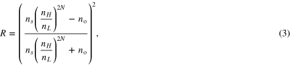
where R is the reflectivity of the coating, ns is the refractive index of the test mass material (assumed to be silicon as may be used in future gravitational wave detectors), nH is the refractive index of the high refractive index coating material (in this case GaP, nH = 3.05), and nL is the refractive index of the low refractive index coating material (in this case AlGaP, nH = 2.77), and no is the refractive index of air. It can be shown that a total of 116 alternating layers of quarter wavelength GaP and AlGaP are required, with a total thickness of 15.5 μm. The displacement thermal noise of the coating can be estimated by [5]:

where w is the incident detector beam radius (the radius at which the light intensity is 1/e2 of maximum), Y is the Young's modulus of the test mass, Y' is the Young's modulus of the coating and t is the total thickness of the coating. We assume the aLIGO beam radius of 6 cm and a laser wavelength of 1550 nm appropriate for use with a silicon substrate.
Figure 5 shows (a) the resulting magnitude of coating thermal noise calculated using both the lowest loss measured at 20 K and the highest loss measured at 20 K, when illuminated with laser light of 1550 nm wavelength. Figure 5(b) shows the expected performance of the current 5.9 μm thick aLIGO room temperature silica/tantala coating (illuminated using a 1064 nm laser), and (c) a 6.87 μm thick silica/tantala coating with suitable layer thicknesses to achieve equivalent reflectivity when used with 1550 nm light and operated at 20 K.
It can be seen from figure 6 that, compared to aLIGO (using silica/titania-doped tantala coatings at room temperature, curve (c)), the use of AlGaP/GaP crystalline coatings operated at 20 K, as in curve (a), offers a factor of 5.8–8.9 potential improvement in coating thermal noise amplitude, using the measured coating losses for the AlGaP/GaP coatings of 3.5 × 10⁻⁵ and 1.4 × 10⁻⁵ respectively. The reduction in temperature from 300 K to 20 K accounts for a factor of ∼3.8 in this improvement, with the remaining factor of ∼2.4 gained through the lower mechanical loss of the crystalline coating materials. Due to the cryogenic peak in loss in the silica/tantala coatings [26, 27, 42], the projected noise performance of GaP/AlGaP with loss of 1.4 × 10⁻⁵ is a factor of ∼5.1 lower than a detector operating with silica/tantala coatings at an operating temperature of 20 K (curve (b)).

Figure 6. Displacement thermal noise of crystalline GaP/AlGaP multilayer coatings as compared to current silica/titania-doped tantala coatings.
Download figure:
Standard image High-resolution image
This suggests that GaP/AlGaP coatings may allow significant performance gains for upgrades to current gravitational wave detectors, and future detectors, with the ability of being directly grown on silicon mirror substrates.
6. Conclusions
We have carried out initial measurements on a multilayer GaP/AlGaP crystalline coating, which show this coating to have a lowest observed mechanical loss of 1.4 × 10⁻⁵ at 12 K, this being a factor of ∼14 lower than current room temperature silica/doped tantala multilayer coatings that will be used in advanced gravitational wave detectors, and a factor of 64 lower than silica/doped tantala at low temperature. GaP/AlGaP crystalline coatings operated at 10–20 K may therefore offer significant coating thermal noise performance gains of a factor of nearly an order of magnitude over second generation room temperature detectors currently under construction. Future analysis of the material properties of AlGaP and loss angles associated with different crystal axis directions may allow further improvement of these coating materials. Such gains in performance would allow future gravitational wave detectors to gain greater astronomical reach at their most sensitive frequencies.
Acknowledgements
We are grateful for the financial support provided by the Science and Technology Facilities Council (STFC), the Scottish Funding Council (SFC), the Royal Society, the Wolfson Foundation, and the University of Glasgow in the UK. IWM is supported by a Royal Society Research Fellowship. DH and RN acknowledge the support of the German Science Foundation under contract SFB TR7. We would like to thank our colleagues in the LSC and VIRGO collaborations and within SUPA for their interest in this work. This paper has LIGO document number P1400059.